

Page 1
TECHNICAL INFORMATION
HOT RUNNER SYSTEMS
Page 2

Start-up Instructions
for männer Hot Runner Valve Gate Systems
Please note: use dehumidified air only. Minimum air pressure required for pin actuation: 6 bar.
MES
1 2 3 4
Turn on mold cooling and
gate cooling before heating
up the hot runner system.
During the heating cycle,
the compressed air for pin
operation must be switched
off.
In general, use the “soft-start“
function of the control system.
Heat the main manifold with
the sprue bushing to approx.
80-90% of the required production temperature.
Turn on the submanifolds
(cylinder blocks) and nozzles.
Heat up the entire system
to production temperature.
5 6 7
Maintain the system at
production temperature
for approx. 5 -10 min. prior
to operating valve pins.
air for pin
6 bar).
operation
(min.
MSS / MMS / MHS / MIS / MXS / MZS
1
Turn on mold cooling and gate
cooling before heating up the
hot runner system.
4
Maintain the system at production
temperature for approx. 5-10 minutes
prior to operating valve pins.
2 3
In general, use the “soft-start“ function
of the hot runner control system. Heat
up manifold to approx. 80-90% of the
required production temperature.
5
After the system is fully heated,
start production.
Start production.Turn on the compressed
Turn on the nozzles, and heat up
the entire system to production
temperature.
When starting up after a production
stop, purge the barrel of all remaining
resin before restarting. For start-up,
reduce the injection volume to 70%
of the required amount.
IMPORTANT!
When starting up after a production stop, purge the barrel
of all remaining resin before
restarting. For start-up, reduce the injection volume to
70% of the required amount.
IMPORTANT!
FILLING
Several injection cycles may be required
to fill the hot runner system the first
time the unit is used. Continually check
the cavities after each cycle and remove
all short shots until ultimately all parts
are completely filled.
EMPTYING THE INJECTION UNIT
To prevent the gate orifices and valve
pin s from be ing dam aged by co ld
material, do not actuate the valve pins
while setting up the injection molding
machine or while emptying the injection
unit of any remaining material.
PRODUCTION STOP
Re duce the tempera ture of t he hot
runner heating system to standby temperature (100° C to 150° C, depending
on the resin). The valve pins should be
in closed position.
SYSTEM SHUTDOWN
When shuttin g down th e hot r unner
system, switch off all control circuits at
the same time. To prevent the hot runner
system from being damaged by heat
accumulation, allow the mold cooling
system to run for another 20-30 minutes
at approx. 30° C.
REMOVING THE MOLD INSERTS
Before removing the mold inserts, make
sure that the hot runner is switched off
(temperature not exceeding 60° C) and
the valve pins are in open position.
Page 3
Maintenance Tips
for männer Hot Runner Valve Gate Systems
Polyolefins (f.e. PP/PE)
Approx. 2 million cycles*
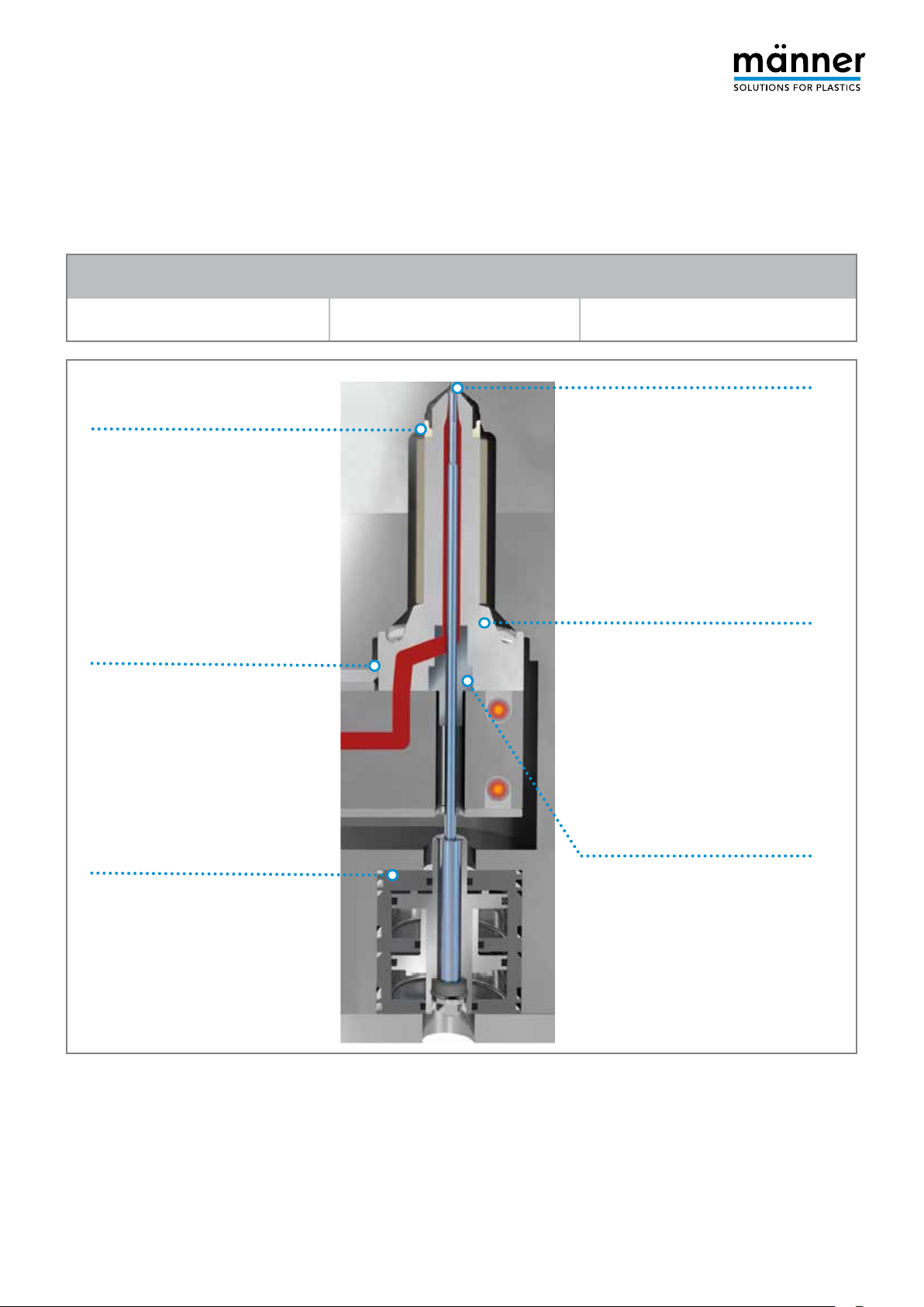
Insulating ring
Check for leaks.
If any leaks are detected, please
contact the männer service team.
Melt flow from manifold to hot
runner nozzle
Check for leaks.
Always replace seals whenever the
components are disassembled.
Polyesters (f.e. PC/PBT/PET)
Approx. 1 million cycles*
Engineered resins (f.e. PA)
Approx. 0.5 million cycles*
Gate
If the surface quality is not satisfactory,
ensure that the valve pin and gate
orifice are not damaged.
If any damage is detected, please
contact the männer service team.
Nozzles
Clean off any dirt or deposits.
NOTE: Do not clean heating elements in high-temperature sand
baths or pyrolysis furnaces.
Pneumatic unit
Only use dehumidified air to
operate the pneumatic unit of
männer hot runner systems.
Remove heavy dirt buildup using
cleaning fluid, and apply pneumatic
grease to the contact surfaces.
Replace any brittle seals.
* The mai nte nan ce inte rva ls spec ifi ed here ar e only a n
approximation. Actual intervals may vary, depending on the
resins used, the injection parameters, and the part geometry.
We will be happy to provide you with maintenance information
for your specific hot runner system and application upon request.
Valve pin guide bushing
and valve pin
Use an ultrasonic cleaning system or
similar equipment to clean off any dirt
or deposits produced as a result of
outgassing.
NOTE: Do not use any abrasives to
clean the valve pin guide bushing or
valve pin.
If any damage is detected, please
contact the männer service team.
We recommend that you check your männer hot
runner system regularly to ensure optimum performance and long life.
Pl ease con tact the männer servic e team if any
damage to the parts is detected.
Page 4

Plug Arrangement
9
10
11
12
13
14
15
16
1
2
3
4
5
6
7
8
N L
Connections
on Mold Side
(EUROMAP 14
Technical Recommendation)
Female connector Male connector
1
+
2
+
3
+
4
+
5
+
6
+
7
+
8
+
9
-
10
-
11
-
12
-
13
-
14
-
15
-
16
-
Thermocouple Power
9
10
11
12
13
14
15
16
N L
in accordance with VDE guidelines
1 Thermocouple connection
2 1.5² wire with ferrule
for blocks
3 Heater band connection
1
2
3
4
5
6
7
8
with ferrule
4 Crimp contact (pin),
1.5² connection
5 Extension, 1.5² wire
6 Parallel connection
(2 tubular heating elements)
7 Parallel connection with
heat-shrink tubing
8 Ring plug
connection
9 Flat plug
connection
10 Ferrule
Grounding
conductors
on mold
connection
Power – Resistance –
Current
Table
The resistance value can vary slightly (±10%) depending on
the temperature and/or cable length.
This deviation in value, however, does not affect the heating
behavior.
Power [W]
P = U² / R
200
250
300
350
400
450
500
600
700
800
900
1000
1500
2000
2500
3000
3500
Resistance [Ω]
R = U / I
264,5
211,5
176,3
151,1
132,2
117,5
105,8
88,1
75,5
66,1
58,7
52,9
35,2
26,4
21,1
17,6
15,1
Current [A]
I = U / R
0,8
1,0
1,3
1,5
1,7
1,9
2,1
2,6
3,0
3,4
3,9
4,3
6,5
8,6
10,8
13,0
15,2
Page 5

Thermocouples
Extension / Compensating Cables
Overview
Thermocouple
Type Material
+
Platinum/13% Rhodium
-
Platinum
R
+
Platinum/10% Rhodium
-
S
Platinum
+
Platinum/20% Rhodium
B
-
Platinum/6% Rhodium
+
Iron
J
-
Copper-nickel
+
Copper
-
Copper-nickel
T
+
Nickel-chromium
E
-
Copper-nickel
IEC 60584 DIN IEC 58 4 DIN 43710 BC 4937
RCA/SCA
RCB/SCB
SoPtRh/
SoPt
BC
JX
TX
See LX
See UX
EX
ANSI MC 96 .1
SX
BX
JX
TX
EX
NF-C 42-32 4
JX/JC
TX/TC
EX/EC
SC
BC
Color coding
not specified
RX/SX
BX
JX
TX
EX
KX
+
K
Nickel-chromium
-
Nickel
KCB
KCA
+
Nickel-chromium-silicon
-
N
Nickel-silicon
+
Copper
-
U
Copper-nickel
+
Iron
L
-
Copper-nickel
NX/NC
* Type J is used for männer thermocouples.
COMPENSATING CABLES
To ensure proper temperature measurement, please note the following.
When connecting the hot (measuring)
junction to the cold (reference) junction
in the control unit, make sure you use
a compensating cable whose wires are
made of original thermocouple material.
Explanation : Wires made of original
the r moco uple mat e rial ex h ibit th e
same thermoelectric behavior as the
KX
NiCr
Ni
Fe
CuNi
VX
UX
LX
thermocouple pair at the hot junction.
As a result, the thermocouple voltage
remains constant all the way to the cold
junction in the control unit.
Thi s c old ju nct ion co mpensat ion is
necessary, since thermocouples measure
the temperature difference between the
hot junction and the cold junction (see
diagram on right). This helps to prevent
parasitic thermocouple voltages.
Insulated
thermocouple wire
Plug connector or
direct connection
KX/KC
VC
WC
Compensating
wire
Color coding
not specified
Measuring unit
control system
Cold junction
KX
VX
NX
of hot runner
Page 6

Voltage Values in µV
for Type J Thermocouple (iron/copper-nickel)
ºC 0 +1 +2 +3 +4 +5 +6 +7 +8 +9
10
20
30
40
50
60
70
80
90
100
110
120
130
140
150
160
170
180
190
200
210
220
230
240
0
507
1019
1537
2059
2585
3116
3650
4187
4726
5269
5814
6360
6909
7459
8010
8562
9115
9669
10224
10779
11334
11889
12445
13000
0
50
558
1071
1589
2111
2638
3169
3703
4240
4781
5323
5868
6415
6964
7514
8065
8618
9171
9725
10279
10834
11389
11945
12500
13056
101
609
1122
1641
2164
2691
3222
3757
4294
4835
5378
5923
6470
7019
7569
8120
8673
9226
9780
10335
10890
11445
12000
12556
13111
151
660
1174
1693
2216
2744
3275
3810
4348
4889
5432
5977
6525
7074
7624
8175
8728
9282
9836
10390
10945
11501
12056
12611
13167
202
711
1226
1745
2269
2797
3329
3864
4402
4943
5487
6032
6579
7129
7679
8231
8783
9337
9891
10446
11001
11556
12111
12667
13222
253
762
1277
1797
2322
2850
3382
3918
4456
4997
5541
6087
6634
7184
7734
8286
8839
9392
9947
10501
11056
11612
12167
12722
13278
303
814
1329
1849
2374
2903
3436
3971
4510
5052
5595
6141
6689
7239
7789
8341
8894
9448
10002
10557
11112
11667
12222
12778
13333
354
865
1381
1902
2427
2956
3489
4025
4564
5106
5650
6196
6744
7294
7844
8396
8949
9503
10057
10612
11167
11723
12278
12833
13389
405
916
1433
1954
2480
3009
3543
4079
4618
5160
5705
6251
6799
7349
7900
8452
9005
9559
10113
10668
11223
11778
12334
12889
13444
456
968
1485
2006
2532
3062
3596
4133
4672
5215
5759
6306
6854
7404
7955
8507
9060
9614
10168
10723
11278
11834
12389
12944
13500
250
260
270
280
290
300
310
320
330
340
350
360
370
380
390
400
410
420
430
440
450
460
13555
14110
14665
15219
15773
16327
16881
17434
17986
18538
19090
19642
20194
20745
21297
21848
22400
22952
23504
24057
24610
25164
13611
14166
14720
15275
15829
16383
16936
17489
18041
18594
19146
19697
20249
20800
21352
21903
22455
23007
23559
24112
24665
25220
13666
14221
14776
15330
15884
16438
16991
17544
18097
18649
19201
19753
20304
20855
21407
21958
22510
23062
23614
24167
24721
25275
13722
14277
14831
15386
15940
16493
17046
17599
18152
18704
19256
19808
20359
20911
21462
22014
22565
23117
23670
24223
24776
25331
13777
14332
14887
15441
15995
16549
17102
17655
18207
18759
19311
19863
20414
20966
21517
22069
22620
23172
23725
24278
24832
25386
13833
14388
14942
15496
16050
16604
17157
17710
18262
18814
19366
19918
20469
21021
21572
22124
22676
23228
23780
24333
24887
25442
13888
14443
14998
15552
16106
16659
17212
17765
18318
18870
19422
19973
20525
21076
21627
22179
22731
23283
23835
24389
24943
25497
13944
14499
15053
15607
16161
16715
17268
17820
18373
18925
19477
20028
20580
21131
21683
22234
22786
23338
23891
24444
24998
25553
13999
14554
15109
15663
16216
16770
17323
17876
18428
18980
19532
20083
20635
21186
21738
22289
22841
23393
23946
24499
25053
25608
14055
14609
15164
15718
16272
16825
17378
17931
18483
19035
19587
20139
20690
21241
21793
22345
22896
23449
24001
24555
25109
25664
Page 7

Control Parameters
männer HCS Hot Runner Temperature Control Systems
männer HCS hot runner temperature control systems
(for example, HCS-TS, HCS 2) use a two-position PID
controller. Its monitoring characteristics are comprised of
proportional, differential and integral control actions.
Proportional band Xp
(Pb1)
Derivative (rate) Tv1
The proportional control action delivers
a control output, which is an undelayed
signal that is proportional to the error.
A small error results in a low control
output, which, however, is not sufficient
to correct the error.
Large proportional action
The derivative control action calculates
the rate of change of the error and
delivers a control output. This signal
is proportional to the rate of change of the error. If the process output
moves away from the setpoint, the
control output increases more rapidly
Large derivative action
IMPORTANT: Control parameters should only
be changed if a desired improvement in quality
cannot be achieved with self-optimization.
The sensitivity of the controller and,
thus, the adjustment to the process are
defined by the gain factor. The inverse
value of the gain is called the proportional band (Xp). The proportional band can
be set to a value from 0.0% to 999.0%.
Fast response by the controller;
possible oscillations
compared to that of a proportional
controller. This is called predictive control. The characteristic parameter is the
derivative (rate) Tv, which can be set to
a value from 0.0 to 999.0 seconds.
Fast response to temperature changes
Integral (reset) Tn1
Cycle time T1
Duty cycle
Small derivative action
The integral control action calculates
the sum of all past errors and delivers
a control output. The integral controller adds together small deviations
between the setpoint and actual process output and increases or decreases
the control output until the deviation is
Large integral action
Small integral action
The cycle time is the time required
to complete the heating and pause
actions for a specific power setting.
The cycle time can be set to a value
from 0.0 to 999.0 seconds.
A duty cycle of 100% means that full
power is delivered to the heating
circuit; a duty cycle of 50% means that
Slow response to temperature changes;
may result in overshoot during start-up
zero. The control output is maintained
until a new error arises. The characteristic parameter is the reset time Tv,
which can be set to a value from 0.0 to
999.0 seconds.
Slow, damped response
Faster response; may result in oscillations
Example: if the cycle time is 60 seconds
and the power setting is 50%, the
heating elements are on for 30 seconds
and then off for 30 seconds.
only half of the power is delivered.
The duty cycle can be set to a value
between 0% and 100%.
Page 8

Otto Männer GmbH
Unter Gereuth 9-11
79353 Bahlingen a. K.
Germany
Phone +49 (0) 7663 609-0
Fax +49 (0) 7663 609-299
info@maenner-group.com
www.maenner-group.com
02/12. Technical specifications subject to change. Actual colors may differ.
 Loading...