

Page 1
OWNER’S MANUAL
MANLEY
STEELHEAD RC
MM/MC GRAMOPHONE CARTRIDGE PREAMPLIFIER
Page 2

CONTENTS
SECTION PAGE
INTRODUCTION 3
INSTALLATION PRECAUTIONS 4
FEATURES AND APPLICATIONS 5
OPERATIONAL NOTES 9
REMORA REMOTE CONTROL OPERATING INSTRUCTIONS 12
TROUBLESHOOTING 16
MAINS CONNECTIONS 18
SPECIFICATIONS 19
rev5/2/11cd
Page 3

INTRODUCTION
THANK YOU!...
...for choosing The MANLEY STEELHEAD RC phono preamplier. Please read over this
manual carefully as it contains information essential to the proper operation and maximum enjoyment of this fabulous instrument.
The MANLEY STEELHEAD RC is designed to provide that rare combination of maximized
sonic performance coupled with a generous ability to adapt to any moving magnet, moving coil
or iron vane phono cartridge you may wish to use. With the STEELHEAD’s feature compliment,
you no longer have to settle for what a given cartridge sounds like with a xed predetermined
preamp load impedance, or wonder what that same cartridge might sound like when presented
with different loading arrangements. What best suits your particular phono cartridge, system, lis-
tening room and personal preference is now merely a ick of a switch away! The STEELHEAD
adapts to accommodate your situation, rather then the other way ‘round.
To this end you will notice that it is the anticipation of your preamplier needs which has
driven every detail of the STEELHEAD’s planning, engineering, styling, operating convenience
and adaptability.
UNPACKING
Unpack the preamplier carefully and make sure that all supplied accessories are present.
Examine all items for any possibility of shipping damage. All six tubes should be standing at attention in their sockets. If the unit is damaged or fails to operate, notify the shipper or your dealer
or us or your local authorities immediately. Or if you suspect The Shipping People threw it off
the airplane and onto your front porch whilst ying overhead at 30,000 feet, notify the ship-ping
company without delay and complain to them as we only guarantee this unit to be able to survive
a drop of 23,487 feet or less.
Your STEELHEAD RC was packed with extreme love and care. Each box includes the following components and accessories:
a) 1 each, 6 foot IEC 3-conductor mains power cable (that you will probably replace with
an expensive audiophile cord anyway.)
b) 1 each, Owner’s Manual per pair (that we hope you will keep reading.)
c) 1 each, Outboard Power Supply Unit with captive grey power cable and big fat connector.
d) 1 each, REMORA Remote Control.
It is prudent to retain the shipping materials for future use, as they are custom-formed for
the preamplier and will greatly minimize the chance of shipping-related damage should you
ever need to put your precious Steelhead in the careless hands of The Shipping People again.
3
Page 4

INSTALLATION PRECAUTIONS
a) Avoid locating the preamp where it will be exposed to direct sunlight, excessive humidity, dust or moisture.
Extreme environments may temporarily or permanently degrade preamp performance.
b) Keep the preamp housing away from sources of strong magnetic eld radiation, such as large video display
CRTs, large power lines or power/audio transformers in nearby equipment. Extra measures have been taken to
shield the magnetically sensitive bits inside the preamp housing. Nevertheless these measures can be over-
whelmed by strong outside inuences. Keep in mind that the tiniest disturbance along with the desired signals
will be amplied many hundreds or thousands of times.
c) Locate the preamp away from heat-radiating sources, such as other large amps, political demagogues or
space-heating equipment.
d) Make sure the preamp and power supply is off before making any system connections. Do not remove or
insert the large 16-pin circular power supply connector when the power supply mains switch is in the on (|)
position. Do not hot plug the system.
e) Dissipate any static electric charge build-up on your body by touching the enclosure before making or chang-
ing any system connections. The preamp electronics are fairly robust as far as immunity to damage from static
charge is concerned, but total immunity cannot be had without unacceptable compromise of audio performance.
f) Be careful to feed only low-level phono cartridge signals to the preamp input connectors. Sustained line-level
signals above 15 volts peak may cause damage to sensitive MC input stages even when the preamp is in the
standby mode or when the power is off.
AC VOLTAGE SELECTION
The STEELHEAD system may be set to operate on either 117 or 234 volts A.C. by means of a rotary switch
located on the power supply P.C. board. The power supply’s mains-voltage selector switch is normally preset to the
mains voltage at the customer’s location prior to shipment. If, however, the preamp provenance is unknown then the
mains-voltage selector switch should be checked and reset to the correct voltage if necessary. The mains fuses must
also be checked for proper ratings and changed if necessary. Failure to correctly set the mains selector switch or use
properly rated fuses can cause extensive damage to the system which is of course not covered by the warranty. The
mains fuse may be checked by rst disconnecting the IEC mains cord from the power supply’s power inlet plug. Then
gently press the small leaf spring on the side of the rectangular gray fuse retainer cap. The fuse and cap should spring
outward toward your ngers. Inspect the fuse for the proper rating; change if necessary. Refer to the fuse-rating chart
in the specications section of this manual.
To inspect or adjust the mains-voltage selector switch it will be necessary to remove the top cover of the
power supply enclosure. For this you will need a #1 Philips screwdriver, and a 3/16 inch at blade driver to change
the selector switch setting.
Before opening make sure that the power supply is unplugged from mains power and the STEELHEAD
preamp. Once inside you will see tall cylindrical high voltage energy-storage capacitors, which can be a shock nuisance even when the supply is not energized. Therefore, if the supply has been recently power cycled, let the supply
capacitors discharge for 15 minutes prior to opening. Then remove 8 Philips 4x40 retaining screws from the cover,
followed by the cover. Locate the voltage selector switch near the mains power entry / fuse / power switch module.
The switch face is the black round object, about 1/2 inch in diameter, with white voltage numbers “110” and “220”
on the rotor and a white triangular selection indicator on the stator. Notice that the “110” and “220” markings on the
switch should not be interpreted as being the precise voltage needed to operate the preamp system. Using the 3/ 16
inch screwdriver rotate the switch, if necessary, so that the mains voltage you intend to feed the power supply lines up
under the selection indicator. Be sure to replace all screws when reassembling.
4
Page 5

FEATURES AND APPLICATIONS
1. HIGH PERFORMANCE FRONT END
The STEELHEAD RC preamplier makes the best use of active and passive component and circuit
developments generated over the past half-century. The hybrid cascode gain blocks simultaneously deliver
wide-band high-gain, low noise and low distortion performance without having to resort to heavy-handed
amounts of negative feedback. Or overly complex circuit topology. The multiplicative aspect of the cascoded
device’s output (anode) impedance means that the most important characteristics of each gain stage are preserved even though the local negative feedback present in each block is very small. This approach makes the
amplication factor of each stage insensitive to tube gain or transconductance variations which occur due to
device production tolerance allowances or aging.
Other uncommon traits include high quiescent and operating current in each gain stage. This lowers
the static and dynamic impedances found within each stage and raises system bandwidth. Musical material
which would cause a cave-in of the typical current-starved 12AX7-based preamplier circuit are conveyed
uninchingly by these amplier stages.
2. ACCURATE “4-CORNER” RIAA EQUALIZATION
In the spirit of high delity, all four RIAA phono equalization corner frequencies or time constants
have been specically addressed in the STEELHEAD preamplier. Historically most designs have concentrated on the “big three” time constants of 3180, 318 and 75 microseconds. This ignores the fourth corner
of about 3.2 us, which when ignored causes most phono stages to continue rolling off the highest octave
signals coming from the phono pickup, rather than turning the nal “corner” and shelving to at response at
about 50 kHz. Careless removal of upper octave bandwidth causes the recovered audio to become somewhat
lifeless and remote, with needless loss of impact, detail and percussiveness. Ironically this signal content is
precisely what is omitted from all currently popular digital audio delivery formats, and is one of the chief
culprits behind the homogenous upper octave sonic characteristics of those formats.
As with all equalizing ampliers intended to correct a given form of frequency-selective emphasis
curve, care must be used when building the restorative compensation networks. Great care must be exercised
if the goal is to produce a highly accurate passive network coupled to low-feedback ampliers. And experience has shown that the effort spent in faithfully adhering to the inverse RIAA equalization curve produces
results that easily justify the additional procurement and manufacturing costs. To this end, only hand-selected and/or 1% tolerance components are used throughout the RIAA equalization network. Add to that the
factory-set variable capacitors, and the result is very high equalization accuracy where small component and
circuit layout variations that other manufacturers ignore are netted out. This yields impeccable inter-channel
phase and gain matching at any gain setting. In short, the STEELHEAD will magnify the differences in the
character and personality of your vinyl recording collection, cartridge, tonearm and turntable. A microscope
for the ear! Be prepared to hear previously undiscovered musical content as you play back your favorites!
5
Page 6

3. SWITCH-SELECTABLE CARTRIDGE LOAD IMPEDANCE
An effective means of varying the load seen by the MC cartridge has been included in the form of
a 5-position rotary switch. This switch selects various taps on a specially manufactured dual-primary bi-
lar wound, high-bandwidth low-resistance and multiple-shielded nickel-core step-up autoformer. A drama
to make, the autoformer permits the minute MC cartridge signal power to be efciently and transparently
transformed from low-volts/high-current to high-volts/ low-current. By avoiding conventional parasitic
cartridge termination resistors, none of the MC cartridge’s tiny signal power is thrown away before am-
plication. This results in improved system signal-to-noise ratio. Quite worthwhile provided, as in the
STEELHEAD, the autoformer has the necessary performance for the job. This pivotal component has had
engineering attention lavished upon it in the only way possible or practical: The Manley Labs magnetics
department. In-house transformer prototyping and manufacturing capabilities permit realization of extraordinary transformer designs.
You may now audition your MC cartridge at or near the manufacturer’s specied loading resistance without sacricing any signal power through a parasitic load resistor. And explore the interesting
tonal shifts caused by intentional mild or severe mis-termination of the cartridge. The “right” setting will
ultimately depend on the cartridge in use, type of music being heard, other downstream equipment and,
most importantly, your personal preference. There will no doubt be moments when a technically “wrong”
setting will be musically “right” for a given situation. Do rest assured that, in this instance, a technically
wrong setting is completely harmless for all equipment involved.
In the case of the MM input, the typically higher cartridge output levels allow xed resistor termination, with clockwise-most switch setting being the standard 47k-ohm load resistance. Those MM cartridges
capable of properly driving low impedance loads between 25 and 400 ohms should be auditioned through
both the MM and MC inputs. By doing so you may nd the most appropriate sonic character through the
use of unconventional input arrangements. In short, experiment; don’t let the control labeling stop you. On
the contrary, we invite you to tweak away!
4. SWITCH-SELECTABLE CARTRIDGE TERMINATION CAPACITANCE on the front
panel yet!
Termination capacitance may be applied to each channel independently in 10 pF steps, up to 1100 pico-
Farads. The termination capacitance is present at the gain-stage inputs, and is not affected by input selector
or gain switch changes. For best accuracy consult your phono interconnect cable literature or manufacturer to
determine how much of the termination capacitance may be attributed to the cable. Then subtract at least that
amount from the target capacitive termination value.
If the interconnect manufacturer does not know the amount of capacitance per unit length that their wire
presents (!), then refer to the following example for a starting point: Typical phono interconnect cables will
exhibit self-capacitance on the order of about 30 pF per foot. If the interconnect cable is 3 feet (~ 1 meter) in
length, you may expect about 90-100 pF of input capacitance to be present due to the interconnect cable alone.
If the cartridge manufacturer species a load capacitance of 150 pF then it is best to subtract the cable’s portion, i.e. 90 pF. This yields a balance of 60 pF. Thus, the audition should start with the termination capacitance
switches set to 60 pF.
6
Page 7

Each cartridge manufacturer’s product will work best in a laboratory sense when terminated
(loaded) with a certain amount of resistance and capacitance. By lab sense it is meant that the signal
developed by the cartridge is at maximum power transfer into the pre-amp, with minimum overshoot and
ringing, attest frequency response and gentle roll-off characteristics. But it is those settings that create the
most musically satisfying results for you that are of uppermost importance. And your termination preferences may rightly deviate unpredictably from some lab-based norm. A good place to start is with those
values recommended by the cartridge manufacturer, less the interconnect cable capacitance. A good default
value, if the recommended cartridge load capacitance is unknown, is 150 pF, the sum of cable and termination capacitance switch settings. This value reects a de facto standard as used by pre-amp manufacturers
past and present. From there we encourage you to scrutinize a range of switch settings until you nd those
values which best suit you and your accompanying components.
Also notice that the audible affects of varying the termination capacitance can differ substantially
between cartridge types and brands. This is to be expected due to the greatly varying source impedance
characteristics of the cartridges available today. In general you may expect the termination capacitance
value to alter, at one extreme, subtle imaging and spatial cues, and at the other high-frequency content,
forwardness and speed of the reproduced sound. As with the load Z switch, feel free to tune the termination
capacitance switches for maximum sonic satisfaction even though the nal setting differs from the cartridge manufacturer’s specs.
5. SWITCH-SELECTABLE AMPLIFIER GAIN
Cartridge output levels and downstream line-level interconnect drive voltage requirements can vary
greatly between manufacturers. Hence a four-step amplier-block gain control has been included to accommodate these differences, as well as differing cartridge sensitivities. You may select from 50 to 65 dB
of gain in 5 dB steps. The gain gure is referred to amplier gain at 1 kHz. Notice that the pre-amp gain is
about 20 dB higher (10 times) at 20 Hz and about 20 dB lower (0.1 times) at 20,000 Hz. The MC step-up
autoformer may also provide approximately 2 to 12 dB of additional voltage gain depending on cartridge
source impedance and load switch setting.
6. PUSH-BUTTON SWITCH FUNCTIONS
Four feature switches have been provided for a variety of utility functions.
MUTE kills audio signals present at both the FIXED and VARIABLE outputs.
DIM reduces the output level by 20 dB, or about 1/4 previous volume. The DIM function is effective at the VARIable outputs only. Notice that preamp specications at the VARIable output may be
slightly compromised with the DIM feature engaged. This feature should be treated as a convenience for
use when, for example, cueing up a record. System-menacing pops and thumps due to needle-drop are
held at bay yet sound from the pick-up may still be heard.
SUM combines the amplied audio into a binaural signal, present at the VARIable outputs only.
Monophonic or the lateral-only modulation content of your stereo records may now be heard. True mono
may be experienced if the feed to one of your two loudspeakers is cut.
SLEEP toggles the STEELHEAD between normal operating state and a near zero-power sleep
mode. No operating voltages are present when in sleep mode, except for some keep-alive CMOS system
control logic, energized by a separate small mains transformer in the power supply.
7
Page 8

8. LINE INPUT SELECT BUTTON
The LINE switch routes external line level signals to the top of the feature switch stack, and through
the VOLUME control. In this way, an external signal source may be manipulated by the SUM, DIM and MUTE
switches, along with the volume control, before transmission to any downstream power ampliers. Notice here
that the Steelhead’s VARIable internal line driver does not have any voltage gain, but does have power gain by
virtue of its low output impedance. Since most line level gear these days has plent of output level, the last thing
you probably need in your system is more gain. Thus, this LINE input allows you to run a CD player (for instance)
into the Steelhead, control the volume and let the Steelhead’s Variable Outputs go drive your ampliers. Or if you
have many LINE level sources, you can run the output of another preamplier or passive switching device(such as
a Manley SKIPJACK) into the Steeelhead’s LINE input. It’s novel. Try it.
In addition, when the LINE function is invoked, the phono stage remains active, and any cartridge signals
present will appear in amplied form at the Steelhead’s FIXED outputs. Thus, the preamplier’s dual signal paths
may be applied simultaneously, i.e.; listening to the LINE input signal while, for example, recording material from
the phono stages.
When the LINE feature is not engaged, the phono signals travel through the complete path normally, as
described for the line signal above. Notice that the line signal is subject to a fairly demanding 500 ohm termination
resistance (not a short-circuit) when the LINE feature is not engaged. This helps cut down on crosstalk between
the line and phono signals inside the STEELHEAD enclosure.
8. BUFFERED VOLUME CONTROL
The STEELHEAD is equipped to drive external power ampliers directly via low output impedance
VARIable line drivers. Purists may easily bypass other outboard preamplier circuitry by connecting power amplier inputs directly to the STEELHEAD’s VARIable output jacks.
9. SEPARATE BUFFERED FIXED AND VARIABLE OUTPUTS.
Choice of constant-level source for interconnection to a line-level-only pre-amp or recorder, and variable
outputs for direct connection to power ampliers.
10. TWO-STAGE RF INTERFERENCE SHUNTS.
One set of dual dip switches per channel for selective shunting of annoying radiofrequency energy to the
STEELHEAD chassis, or earth ground. These switches are located on the rear apron, nested within each channel’s
cluster of RCA jacks. These switchable shunts effectively connect the signal ground to the chassis ground at high
frequencies only. Switch the shunt switches on as needed if RFI is encountered. Notice that the shunts are made
switchable for those installations where having a permanent shunt connection would, due to innumerable saftey
and signal grounding arrangements, provoke unacceptably audible “buzz current” ground loops for some users.
Notice that these shunts are not part of the signal path.
11. DISCRETE SYSTEM COMMON AND EARTH GROUND POINTS.
Breakable link between electronics common “zero volts” point and chassis ground allows great exibility
in grounding arrangements.
12. REMOTE HIGH PERFORMANCE POWER SUPPLY.
Multiple channel power supply in separate enclosure eliminates supply proximity-based noise intrusions
into the signal path. Robust and regulated ultra quiet high-voltage rail maintains electrical quiet of sensitive input
stage amps. Each voltage channel is conveyed to the preamplier via separate source and sink lines; no common
supply points except at the star-grounding point on the amplier boards. Multi-core interconnect cable is screened
via tinned overall shield braid.
13. REMORA REMOTE CONTROL.
The REMORA is a radio-frequency based remote control that allows command of the silicon-free, high-
quality motorized VOLUME attenuator set, for innitely resolvable control of listening levels. No need to “point”
the remote in any direction - the Steelhead’s attenuator can be controlled from another nearby room, through walls,
through oors, through doors, and through opaque closet or cabinet doors! Please, no need to get up. Sit back.
Relax. Enjoy.
8
Page 9

OPERATIONAL NOTES
PREPARATION FOR INSTALLATION
Budget a suitable space in which to place the preamplier, power supply and associated interconnect cable. This space should be free of strong external magnetic and RF elds, and reasonably removed from strong loudspeaker-generated acoustical elds. This space should also be free
of excessive heat or dust and large enough to permit easy ow of cool air to the top, bottom and
sides of the preamp and power supply.
Make sure the power supply’s mains voltage selector switch is set to match the local line
voltage, and the wire link is present between the preamp’s green CHASSIS and black CIRCUIT
ground mini binding posts on the rear panel.
Try to position the power supply away from any interconnect cables which may be carrying
audio signals.
BEFORE POWER-UP
Once placed, join the power supply cable to the pre-amplier via the large16-pin circular
connector. The 16-pin connectors are keyed and can only be mated when both halves are lined
up correctly. Check and make sure the power supply is switched off, then attach the grounded
IEC power cable jack to the IEC plug. Keep the power off until all other system connections are
completed.
Proceed by connecting the input and output cabling to the signal sources and loads as de-
sired. Tie any separate turntable or tonearm ground lead to the gold CHASSIS ground binding
Set the GAIN dB control to 55 dB and VOLUME control to about 9 o’clock. Choose the
MM or an MC input, as necessary, with the INPUT control. Place the LOAD Z switch to a value
at or near that recommended by the cartridge manufacturer. Adjust the LOAD CAP switches to
a value at or near that recommended by the cartridge manufacturer less any interconnect cable
capacitance. Select and clean, if necessary, your favorite gramophone record....
Plug the power cable in and place the power supply’s mains power switch in the on (|) position. The SLEEP switch should glow. Push the SLEEP switch. The SLEEP switch will go dark,
selected INPUT and GAIN blue LED’s will illuminate, the MUTE switch lamp will start ashing and the power supply pilot LED and the MANLEY STEELHEAD RC badge will light up.
The winking MUTE lamp indicates the beginning of a 30 second warm-up mute delay,
during which time the muting relay is engaged; no output will be heard from the preamp.
9
Page 10

DURING OPERATION
Once audio is heard from the STEELHEAD the exploration for the ideal control settings
can begin. However it would be best to allow about 15 minutes of warm-up time for the system to
reach thermal equilibrium.
Again, notice that the MUTE function operates over both FIXED and VARIable outputs,
while the DIM and SUM functions are only available at the VARIable output jacks.
RETURNING TO STANDBY MODE
At the conclusion of your listening session press the SLEEP switch again to cut power
to the preamp. Notice that effort has been made to keep power engagement and cessation noise
generated by the preamp to a minimum. Nevertheless it is wise to remove power mains and signal
feed to your power amps when the preamp is undergoing a power state change.
Additionally, it is best to return the STEELHEAD to the SLEEP mode when not in use
rather then leaving the power on indenitely. This will enhance tube and system life. The tubes
should last thousands of hours under normal conditions.
REPLACING A TUBE OR ILLUMINATED BADGE LAMP
Yes there are user-servicable parts inside! But, as with other vacuum tube based products,
there is also high voltage present. Therefore caution must be used when covers are removed; oth-
erwise there could be shock hazard. As with all mains-powered gear make sure the mains power is
off and mains cords are unplugged. Then unplug the power supply from the preamp. If the preamp
has been powered up within the last 15 minutes stop! and let the large internal capacitors nish discharging. Wait about 5 minutes before opening the preamp once the 16-pin connector is unplugged.
You will need a #1 Philips screwdriver and a small slot driver.
FUSE-LAMP REPLACEMENT: *Note: Units shipped after 5/2003 use long-lasting LEDs
that will probably never burn out. For units built before then:
After removing the cover use the small slot driver to help pry the badge’s fuse-lamp out of
the clip holder. Use one hand only when reaching into the enclosure or touching any components
inside. Keep the other hand away from the preamp, preferably in your pocket.
TUBE REPLACEMENT: Increased noise level whether gradual or abrupt can generally be
attributed to aging tubes. Gradual noise increase from weakened tube cathode emission is the chief
symptom of an aging tube, which may be accompanied by exaggerated distortion or loss of headroom. The noise may be a variation in the level of hiss, or the noise may develop a more granular
“large-curd” quality. Should these symptoms appear, unplug the tubes in the offending channel
and replace with new devices of known-good quality. If the front-end 6922 tube is being replaced
in one channel it is wise to replace the same tube in the alternate channel, preferably with matching manufacturer and date code if possible.
10
Page 11
Let the preamp tube(s) cool down, if necessary, before handling. Tube heater laments are
somewhat more suceptable to damage when warm or hot.
Each tube should require only moderate force for removal and replacement. Gently rock
the tube back and forth a bit during removal or replacement. Avoid bending the circuit board. Notice that the heaters of the 6922s are connected in series, and neither channel will function if one
of the laments is open or burned out, or unless both of the 6922s are installed. Akin to those old
Xmas tree lights in the attic, no? Be careful to straighten any bent tube pins prior to installation;
pin misalignment will make tting the replacement tube difcult or impossible, and may damage
the socket. Be careful to put replacement tubes in the proper sockets.
Never substitute other type numbers of 9-pin tubes without careful research. There are literally
thousands of types that share the 9-pin mechanical basing arrangement, but NOT the internal
electrical connections! Mechanically compatible tube plugs and sockets by no means indicate
electrical compatibility! And random experimenting can easily and quickly destroy the substitute
tube and other parts of the preamp!
Three tube types that are electrically and plug-socket compatible with the 6922 dual triode
are the 7308, 6DJ8 and the ECC88 / E88CC.
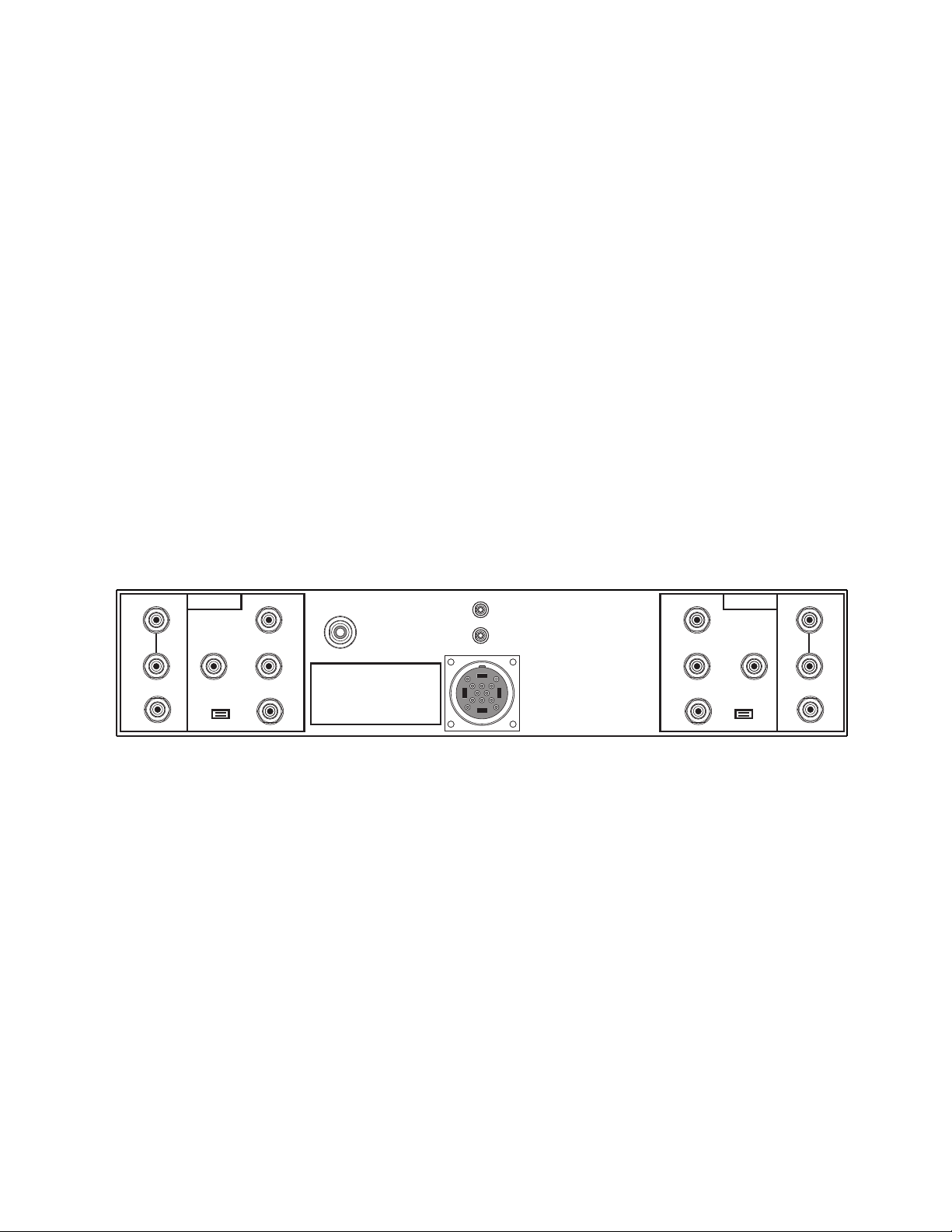
VARI
FIXED
RIGHT
LINE IN
RFI SHUNT
ON
1
2
OFF
MC-1 IN
MC-2 IN
MM IN
CHASSIS
GROUND
CIRCUIT
SERIAL #
MC-1 IN
MC-2 IN
MM IN
LEFT
LINE IN
RFI SHUNT
OFF
ON
1
2
Please direct any questions to your dealer or MANLEY LABS for further assistance:
service@manleylabs.com
VARI
FIXED
11
Page 12

REMORA REMOTE CONTROL
OPERATING INSTRUCTIONS
Quick Start:
Your Remora Remote Control system has been congured and tested at the factory to verify that the communication link between the radio frequency transmitter and the mating receiver-decoder inside the Steelhead has
been properly established.
Before beginning, ensure that a fresh 9V alkaline battery has been installed in the Remora Remote transmitter.
Yes, we installed a new 9V battery in the Remora Remote when it left the factory.
Turn on the Steelhead RC and after a few seconds, push and hold either the up or down command buttons.
The command is sent via radio signal to the preamplier and the motorized volume control will react by moving as directed by the remote switch activation, with motor action occurring as long as a button is engaged.
The Remora Remote transmitter’s multi-colored LED lamp will glow bright GREEN when a command is
being sent.
Notice that the volume control motion will stop when the control reaches the travel end-stops, just as it does
when the knob is turned by hand. Also notice that the remote will stop transmitting if either the up or down
buttons are pressed for more than 30 seconds.
The multi-colored LED lamp on the face of the remote will tell you when the 9V battery needs to be replaced.
The battery is GOOD when the lamp is bright GREEN while the transmitter is active. As the battery voltage
wanes, the green light may ash RED briey when the transmitter is switched on; that’s when the load on the
battery is heaviest. When the battery is nearing exhaustion, the time interval of the RED ash will expand, and
eventually and the battery nears life end, the lamp may stay RED more or less continuously. When the LED
lamp stays RED, then the moment has arrived for mandatory replacement of the battery.
You may replace the battery at your leisure, since all the Remora Remote transmitter’s settings are held safely
and indenitely, in the microprocessor’s non-volatile ash memory.
More Details:
Here are some details about the features included with your new Remora Remote system. Some are pretty
obvious; others are riding just below the surface.
First, the Remora radio-frequency remote control system consists of four parts.
1. The microprocessor-controlled battery-operated hand-held RF transmitter
2. The line-operated RF receiver
3. The microprocessor-controlled decoder and motor drive amplier
4. The dual-deck motorized volume control
Using computer-based hardware on both sides of the system adds exibility and allows enhanced features to
be added with little impact on system cost. For example, one such feature is the ability of the receiver-decoder
to discriminate between interfering signals, or other Manley Remora Remote enabled preamplier models so
that it will react only to the prescribed remote transmitter.
...Please read on for more Remora Writings...
12
Page 13

Remora Remote Features!
1. Remote transmitter and receiver operate under crystal-clocked microprocessor control for maximum signal
discrimination, exibility, and system range.
2. The user may easily reprogram the user-number portion of the remote system’s serial I.D. data stream. This
will eliminate the possibility of undesired operation due to remote command collisions.
3. Multi-color LED displays battery condition when the transmitter is in use, as well as two-digit user-number
programming status when in program mode.
4. Internal antennas contribute to sleek design aesthetics and eliminate possibility of damage to them had they
been subject to external exposure, while still providing good range.
5. Transmitter uses readily-available 9V battery.
6. Transmitter shell made of tough Lexan® for durability.
7. Real compression-dome push buttons instead of short-lived conductive silicone membrane pads are used for
years of dependable operation.
8. Highest quality motorized attenuator employed for critical audio path with very good inter-channel match-
ing (no silicon attenuators here!)
9. Two-step attenuator rotation speed: Press and hold a button; for the rst half second the attenuator motor runs slowly so the user may “nibble” at the volume setting. After half of a second, the motor rotation rate
doubles to move things right along.
10. Remote transmitter keep-alive interval keeps Remora Remote awake for a few seconds AFTER either button is released, as indicated by the LED lamp glowing DIM green or red. Keeping the microprocessor awake
shaves a few dozen milliseconds off of the wake-up time, and helps to make the remote system more responsive.
11. Flash memory inside both the transmitter’s and the receiver-decoder’s CPU eliminates the need for backup batteries or super-caps, etc.
12. Clever system architecture and user-programming procedure eliminates the need for dip-switches and as-
sociated ddling with awkward dip switch arrays.
13. Remora Remote consumes very little power which yields long battery life.
14. Electrically quiet operation preserves low noise oor of the preamplier’s audio path.
15. Discrete passive volume control offers highest headroom option over silicon-based devices.
Precautions when using the Remora Remote system:
Use only fresh alkaline 9-volt (006P) batteries in the remote transmitter. The power draw is small during
transmit events, and nil when on standby. Unless the transmitter is used very heavily, the battery should last
for at least a year, or for about 10 hours of continuous transmit time. If the remote not used very often then the
battery life should equal its shelf life.
The remote transmitter operates on 433.9 MHz, and features a tuned antenna for reasonable efciency and
extended battery life. As with other RF equipment of this sort, the range can be inuenced if the antennas on
either side of the link are hampered by obstructions that deect or attenuate the radio signal. Neither the trans-
mitter nor the receiver should be used or placed behind conductive surface planes, or on top of large metal
cabinetry, since this can effectively reduce or block the radio signals.
The tuned antenna is positioned at the top or “nose” of the transmitter housing. Best range can be obtained by
keeping your hand clear of the top of the enclosure during operation. Range may be severely cut if the remote
is placed on a conductive (metal) surface, such as a ling cabinet or other piece of equipment, since the metal
plane will grossly detune the antenna. When the transmitter is operated in the palm of your hand, you may
expect the remote range to be at least 15 meters line-of-sight, typically 20 meters (or more) in most settings.
Radio-based systems can be affected by noise or interference occurring on the operating channel. Various government bureaucracies dictate what radio channels may be used depending on several factors such as country
where the remote system is to be operated, the exact nature of the transmitted information and so forth. Because of these limitations, the channels used for remote controls of this sort can be crowded, especially where
population density is high. In addition to on-channel interference, the desired radio signal may be received
perfectly when the remote transmitter is in one location, but mysteriously “drop out” when the transmitter is
move a few inches one way or another. The transmitter may need to be rotated or relocated slightly to avoid
RF “null” points.
13
Page 14

The Remora system is highly resistant to false operation due to noise or other remote signals, but the range
will be reduced if the competing signals or noise is very strong. If you experience intermittently poor range,
briey try operating the equipment at another location free of possible sources of interference before contacting your dealer or Manley Labs.
Keep the remote and all other parts of the system away from rain or moisture of any sort. The Remora Remote’s circuitry is extremely intolerant of moisture intrusion. In the event the remote transmitter gets wet,
remove the battery immediately, disassemble the case and try to remove as much moisture as possible as soon
as you can. Then let the assembly air-dry in a warm place for a day before re-assembling and testing. DO NOT
disturb any trimpot settings or move the antenna components.
Remove the battery promptly when it becomes weak or discharged or if the remote transmitter is not going to
be used for a protracted period of time. This will help prevent corrosion due to battery leakage.
The motorized volume attenuator may safely be actuated by hand, or by the motor under remote command.
The attenuator has a slip-clutch transmission, so it is safe to occasionally over-ride the motorized action by
hand, or let the clutch slip after the attenuator reaches its end stop. However, the motorized attenuator assembly will last longer if these actions are avoided.
How to establish the digital link (pairing) between the Remora transmitter and the receiver:
Each transmitter and receiver-decoder set is designed to respond to a specic data string as programmed into
the transmitter and later acknowledged by the receiver-decoder. A small set of user-dened user-numbers is
used as part of the data string so that the remote system can be programmed to avoid unwanted operation of
another Remora-enabled Manley preamplier that may be nearby, in range of the transmitter.
If necessary, you may alter the specic short user-number of the transmitter. When you do so, the receiver can
easily be reprogrammed to follow the changes and react to the new user-number. Having unique handshake
ID codes is important for RF remotes since unlike infrared systems, the remote’s RF commands can penetrate
walls, oors, and doors, which might operate other Manley Remora-enabled gear if they all had the same usernumbers!
The user-numbers are a pair of single-digit numbers created by hitting the up and down buttons during a
remote transmitter programming session. How to program the user-numbers is one of those procedures that is
harder to write down than to actually do physically.
To get acquainted with the remote transmitter itself, we’ll start with a simple matter of determining the Remora Remote’s user-number setting without changing the user-number. This requires only one action by you, the
user. You’ll get to see some of the Remora Remote’s “modes” as indicated by the LED lamp.
How to query the Remora transmitter to see what user-number is already programmed:
Press and hold both the up and down buttons for about 0.5 seconds. Release the buttons when you see the LED
change from dim green to ashing dim yellow.
The LED will ash dim yellow for about three seconds. Be careful not to touch any buttons while the LED is
ashing dim yellow as the remote is in the program mode during this time.
The ashing dim yellow LED will time out and will then go dark for a moment. Then the LED will recite the
user-number by ashing a string of GREEN (up) blinks, then a string of RED (down) blinks. The user-number
may range from the smallest value of 1 green, 1 red (1,1) up to a maximum of 7 green and 7 red (7,7). As you
can see, up to 49 different user-numbers are available.
Once the user-number readout event lapses, the remote falls back to normal operation.
How many GREEN blinks? (----- , -----) How many RED blinks?
UP This is your user-number. DOWN
14
Page 15

How to change the user-numbers and re-pair the system:
Ordinarily there will seldom be a need to change the user-number. Changing the user-number requires a few
more ballet steps, as listed below. Some steps are time-window sensitive to help prevent pairing errors due to
interference from other signals on the radio channel.Please read over the list of required actions and LED reactions completely before attempting to reprogram your Remora system user-number.
1. Make sure the Steelhead’s power supply is powered ON, but the audio unit is in SLEEP mode. Also make
sure the batteries in the Remora Remote are healthy.
2. Put the Remora Remote into the programming mode by pressing the up and down buttons simultaneously
for about a half second. The LED will blink yellow to indicate that it is in programming mode.
3. While the LED is blinking yellow, enter the new user-number by tapping the “UP” button 1 to 7 times,
followed by pressing the “DOWN” button 1 to 7 times. Example: 3 “ups” and 2 “downs” will set a new user-
number to (3,2). After it has accepted your new code, yellow blinking LED will stop blinking and will then
read back the new user-number you set by displaying 3 GREEN blinks followed by 2 RED blinks. BE CARE-
FUL NOT to touch the buttons once the read-back has happened; the remote knows you have reprogrammed
it, and it is “armed” with a special data string to tell the receiver-decoder that a user-number change has hap-
pened.
4. With the Remora Remote in this “armed” state and with it in your hand with your thumb hovering over
either button, awaken the Steelhead from SLEEP mode by pressing the SLEEP button. Once the preamplier’s
badge lamp is lit, you have about 1.5 seconds to press either button on the remote. The preamplier should
now respond by rotating the volume control in the direction of which ever button has been pressed. Pairing is
now complete.
For the rst 1.5 seconds after power-up, the Steelhead’s receiver-decoder is congured to be in programming
mode looking for any new user-number changes. If the decoder detects the new user-number programming
string from an “armed” remote during this 1.5 second interval, the decoder will immediately discard the old
user-number and adopt the new one before resuming normal operation.
In the event that you lose or damage your Remora Remote, a new one can be supplied pre-programmed with
your user-number if you provide it to us. Otherwise, it is a straightforward matter to observe, note, and re-pair
the Remora Remote’s user-number to the preamplier using the query and programming procedure described
earlier.
Please direct any comments or questions to your dealer or to Manley Labs for further assistance.
** FCC STATEMENT **
This equipment has been tested and found to comply with the limits for a class B digital device, pursuant to
part 15 of the FCC Rules. These limits are designed to provide reasonable protection against harmful interference in a residential installation. This equipment generates, uses and can radiate radio frequency energy and
if not installed and used in accordance with the instructions, may cause harmful interference to radio communications. However, there is no guarantee that interference will not occur in a particular installation. If
this equipment does cause harmful interference to radio or television reception, which can be determined by
turning the equipment off and on, the user is encouraged to try to correct the interference by one or more of the
following measures:
* Reorient or relocate the receiving antenna.
* Increase the separation between the equipment and receiver.
* Connect the equipment into an outlet on a circuit different from that to which the receiver is connected.
* Consult the dealer or an experienced radio/TV technician for help.
Operation with non-approved equipment is likely to result in interference to radio and TV reception. The user
is cautioned that changes and modications made to the equipment without the approval of manufacturer
could void the user’s authority to operate this equipment.
15
Page 16
TROUBLESHOOTING
The STEELHEAD’s system architecture is designed with a variety of features so as to allow exibility in accommodating as many cartridges and as much downstream gear as possible. Access to
these capabilities rest on the assumption that all STEELHEAD systems are functioning properly. If
trouble is encountered please review the following short list of symptoms and corrective remedies
before contacting your dealer or us.
Symptom Possible Cause Corrective Action
NO lights, power. Bad mains fuse. Replace with correct fuse.
Bad or unplugged Check cables and outlets.
power cable.
AC outlet not energized.
Rolling Grayout®™ Abandon California, elect Libertarians.
Power supply pilot ON,
‘HEAD not responding. 16-pin connector not seated. Check for proper connection.
Dim badge lamps, LEDs. Mains Voltage selector Check for proper setting.
Weak output. switch set to 220 V instead
of 110 V. Be sure of lo-
cal mains voltage before
changing switch setting!
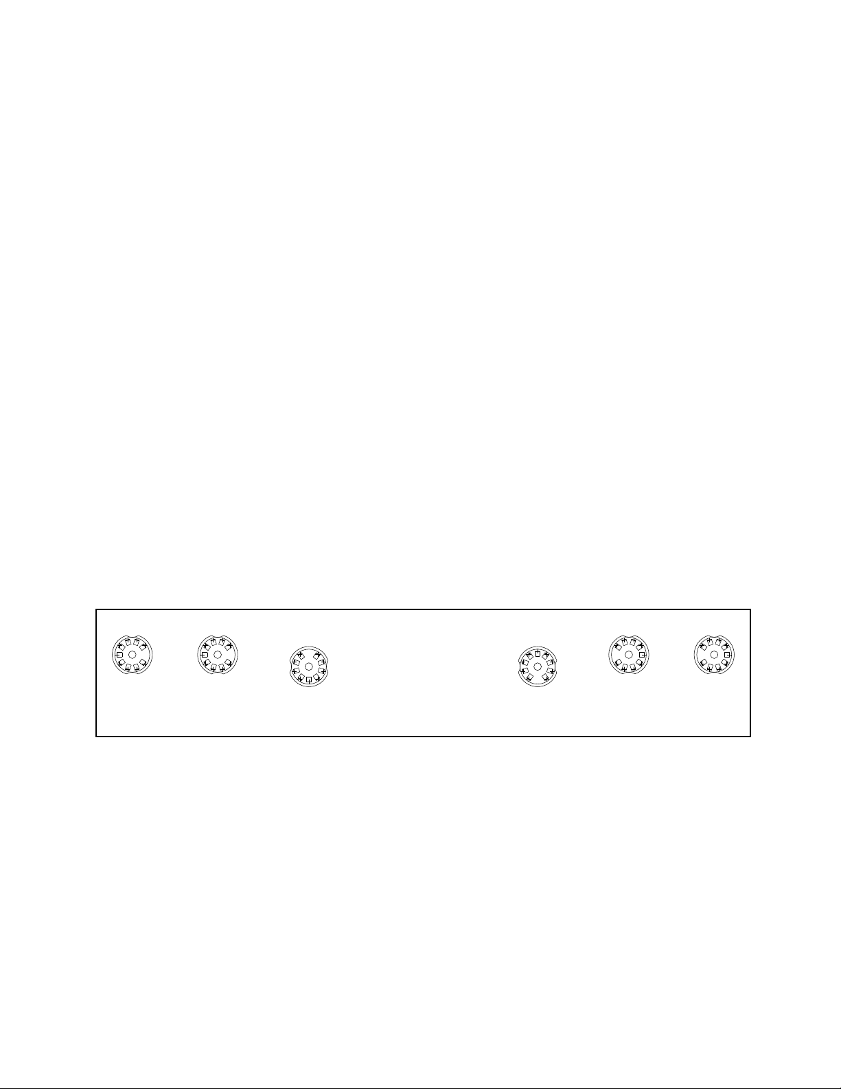
Tube locator diagram RIAA amp board
5687 5687 6922 6922 5687 5687
Output heard in one Bad tube in affected Alternate or replace suspect
channel only. channel. tube(s).
Weak or distorted Bad tube in affected Alternate or replace suspect
output in one channel. channel. tube(s).
16
Page 17

Symptom
Possible Cause
Corrective Action, con’t
Lights ON, no output from either channel after warm-up delay
times out.
Hum heard on unused MM or MC
inputs.
Hum heard on active inputs.
Open 6922 lament, either channel. 6922 unplugged.
Output MUTE function activated.
Input connectors are non-shorting.
Ground link between CHASSIS
and CIRCUIT open.
Turntable/tonearm ground link to
CHASSIS open.
Open cartridge leads.
Phono plugs not fully inserted.
Turntable lines close to hum mag-
netic eld.
Check for glowing 6922 la-
ments. Replace if necessary.
UnMUTE the preamp.
Avoid unused inputs; install
shorting plugs.
Replace jumper if necessary.
Establish inter-chassis connection.
Check lead/head-shell continuity.
Check for proper connection.
Keep source lines away from
transformers, motors, etc.
Ground loop between STEELHEAD and turntable or down-
stream preamp/power ampliers.
Faulty shield connection, input or
output interconnect cables.
No or bad sound heard on MC2
input.
Remarks on hum pick-up: Please be aware that the STEELHEAD can develop voltage amplication
factors as high as 30,000 times, or 90 dB at the 50-60 Hz power line “hum” frequencies. It is of the utmost
importance that cables handling the tiny signals from the phono cartridges be of high quality, with good
screening and connection properties, if the single-ended signal is to have any chance of being received by
the preamp reasonably free from hum and noise intrusions. This is especially true formoving coil pickups.
Please use the shortest practical interconnects and carefully route these away from all possible electrical or
magnetic hum or interference sources.
Check DIN plug wiring:
Left: 1 high, 4 low.
Right: 3 high, 5 low.
Shield: 2 earth, chassis.
Break ground connection of one
or two of the three system elements. Experimentation may be
necessary.
Roll or swap cables, or replace
cables.
Re-wire plug for continuity.
17
Page 18

MAINS CONNECTIONS
Your STEELHEAD RC has been factory set to the correct mains voltage for your country. The voltage setting is
marked on the serial badge, located on the rear panel. Check that this complies with your local supply.
Exportunitsforcertainmarketshaveamouldedmainsplugttedtocomplywithlocalrequirements.Ifyourunit
doesnothaveaplugttedthecolouredwiresshouldbeconnectedtotheappropriateplugterminalsinaccordancewith
the following code:
GREEN/YELLOW EARTH
BLUE NEUTRAL
BROWN LIVE
As the colours of the wires in the mains lead may not correspond with the coloured marking identifying the terminals in your plug proceed as follows:
The wire which is coloured GREEN/YELLOW must be connected to the terminal in the plug which is marked
by the letter E or by the safety earth symbol or coloured GREEN or GREEN and YELLOW.
The wire which is coloured BLUE must be connected to the terminal in the plug which is marked by the letter
N or coloured BLACK.
The wire which is coloured BROWN must be connected to the terminal in the plug which is marked by the
letter L or coloured RED.
DO NOT CONNECT/SWITCH ON THE MAINS SUPPLY UNTIL ALL OTHER CONNECTIONS HAVE
BEEN MADE.
Note: 120 to 240VAC operation changeable with power transformer rewiring
via internal switch and fuse value change.
100VAC operation changeover achieved via rewiring of power transformer PCB.
100-120V Operation: Uses a 1.5A MDL SLO-BLO fuse.
220-240V Operation: Uses a 0.75A MDL SLO-BLO fuse.
Waste Electrical and Electronic Equipment (WEEE)
Informationforcustomers:
TheEuropeanParliamentandtheCounciloftheEuropeanUnionhaveissuedtheWasteElectricalandElectronicEquipmentDirective.ThepurposeoftheDirectiveisthepreventionofwasteofelectricalandelectronicequipment,andtopromotethereuseandrecyclingandotherformsofrecoveryofsuchwaste.Assuchthe
Directive concerns producers, distributors and consumers.
TheWEEEdirectiverequiresthatbothmanufacturersandend-consumersdisposeofelectricalandelectronicequipmentandpartsinanenvironmentallysafemanner,andthatequipmentandwastearereusedorrecoveredfortheirmaterialsorenergy.Electricalandelectronicequipmentandpartsmustnotbedisposedofwith
normalhouseholdwastage;allelectricalandelectronicequipmentandpartsmustbecollectedanddisposedofseparately.
Productsandequipmentwhichmustbecollectedforreuse,recyclingandotherformsofrecoveryaremarkedwiththefollowingpictogram:
Smallproductsmaynotalwaysbemarkedwiththispictograminwhichcasethisispresentintheinstructionsforuse,ontheguaranteecerticateandprintedonthe
packaging.
Whendisposingofelectricalandelectronicequipmentbyuseofthecollectionsystemsavailableinyourcountry,youprotecttheenvironment,humanhealthand
contributetotheprudentandrationaluseofnaturalresources.Collectingelectricalandelectronicequipmentandwastepreventsthepotentialcontaminationof
naturewiththehazardoussubstanceswhichmaybepresentinelectricalandelectronicproductsandequipment.
YourMANLEYorLANGEVINretailerwillassistwithandadviseyouofthecorrectwayofdisposalinyourcountry.
18
Page 19

SPECIFICATIONS
Vacuum tube compliment: 6922 x 2 (gain) plus 5687 (or 7044) x 4 (output buffers)
Fuse type and ratings: 100-120 VAC: 1.5 Amp MDL slow-blow main
230-240 VAC: 0.75 Amp MDL slow-blow main
Moving Magnet input impedance: 5-step user adjustable via xed low-noise resistors.
25, 50, 100, 200 and 47000 ohms.
Moving Coil input impedance: 5-step user adjustable via multi-tap autoformer:
25, 50, 100, 200 and 400 ohms.
Input Termination Capacitance: Variable in 10 picofarad steps from 10 to 1100 pF.
(1.1 nF). Residual input capacitance less than 40 pF.
Gain Steps: 4-step user adjustable, 50, 55, 60 and 65 dB active gain at 1 kHz referred to FIXED
output jack, 10 k-ohm load. Additional gain available via MC step-up autoformer.
Deviation from RIAA curve: Less than +0.5 / -0.3 dB from 20 Hz to 20 kHz, any gain setting.
Typically less than +/- 1 dB from 10 Hz to 100 kHz
Inter-channel differential phase: Less than 4 degrees from 20 Hz to 20 kHz, any gain setting.
Typically less than 2 degrees.
Inter-channel differential gain: Less than +/- 0.5 dB from 20 Hz to 20 kHz, any gain setting.
Dynamic Range: 101 dB @ 1 kHz, 1% THD
200 ohm source, 47 k-ohm input, @55dB Gain 97 dB @ 1 kHz, 0.1% THD
THD: 0.0042% at 1V output @ 1kHz
REMORA RF REMOTE: controls motorized volume control functions, uses 9v battery
Maximum LINE input level: +30.6dBu @ 1kHz for an output of +29.3dBu @ 0.07% THD
26.5Vrms @ 1kHz for an output of 22.8Vrms @ 0.07% THD
Maximum Output: +27dBm @ 1KHz with 3% THD into 100Kohm load
FIXed Output impedance: 150 ohms. Minimum suggested load greater than 1500 ohms.
VARIable Output impedance: 75 ohms. Minimum suggested load greater than 600 ohms.
GAIN setting Fixed Ouptut Vari O/P
MM Noise (S+N+D) / (N+D): 50 dB: 86 dB 108dB 99dB 86dB
200 ohm source, 47 k-ohm input 55 dB: 84 dB 108dB 99dB 85dB
A-weighted Referred to 2.54 mV 60 dB: 80 dB 108dB 94dB 80dB
rms @ 1 kHz 65 dB: 75 dB 108dB 89dB 75dB
9:00 12:00 V/C FULL
MC Noise (S+N+D) / (N+D): 50 dB: 84 dB 108dB 98dB 85dB
100 ohm source, 100 ohm input 55 dB: 80 dB 108dB 95dB 81dB
A-weighted Referred to 0.5 mV 60 dB: 75 dB 108dB 90dB 76dB
rms@ 1KHz and rated input Z 60 dB: 70 dB 107dB 85dB 71dB
19
 Loading...