

Page 1

CHINOOK
O W N E R S M A N U A L
MOVING COIL & MOVING MAGNET
PHONOGRAPH PREAMPILFIER
Issue 1. Rev 1.0
January 2012
Designed & Manufactured
in the USA by
Manley Laboratories, Inc.
13880 Magnolia Avenue
Chino, California 91710, USA
T: +1 (909) 627 4256
F: +1 (909) 627 4256
emanley@manleylabs.com
www.manley.com
MANLEY
LABORATORIES, INC.
Page 2

CONTENTS
SECTION PAGE
CONTENTS i
INTRODUCTION 1
UNPACKING 1
INSTALLATION PRECAUTIONS 2
FEATURES AND APPLICATIONS 3 - 5
1. Standby & Power Switching 3
2. MM & MC Gain Selection 3
3. Selectable Cartridge Loading 4
4. Load Switching 5
5. High Performance Front End 5
6. Accurate “4-corner” RIAA Equalization 5
OPERATIONAL NOTES 6 - 7
INTERNAL VIEW 8
TROUBLESHOOTING 9
MAINS VOLTAGE SELECTION 10
SPECIFICATIONS 11
MANLEY
LABORATORIES, INC.
Chinook Owners Manual i
Page 3

INTRODUCTION
THANK YOU!...
...for choosing The MANLEY CHINOOK phonograph preamplifier. Please read this manual carefully as
it contains information which is essential to the proper operation and maximum enjoyment of this
fabulous instrument.
With the current resurgence of vinyl playback, MANLEY LABS could see the need for a new design. By
utilizing the same advanced technology as used in our critically-acclaimed flagship STEELHEAD
preamplifier, a new product was developed: the CHINOOK. State-of-the art performance now
available at a fraction of the cost.
Everything from the most exotic 180 gram audiophile pressing, to a 25 cent thrift-store classic will be
reproduced accurately and musically.
The MANLEY CHINOOK is designed to provide that rare combination of optimum sonic performance
coupled with the ability to use either moving magnet or moving coil cartridges.
As we say here at MANLEY LABS: Chino…...OK!
Unpack your Chinook Phono Preamplifier carefully and make sure that all supplied accessories are
present.
Examine all items for any possibility of shipping damage. All four tubes should be standing to
attention in their sockets. If the unit is damaged or fails to operate, notify the dealer who supplied
the unit, contact the shipper if the packing box shows excessive damage and finally contact us if you
are not happy with the response you receive.
Your CHINOOK was packed with extreme love and care. Each box includes the following components
and accessories:
1 x 6 foot Mains Cable IEC 3 to 3 pin connector suitable for your country
(that you will probably replace with an expensive audiophile cord anyway.)
1 x Owners Manual (that we hope you will keep reading.)
It is wise to retain the shipping materials for future use, as they are custom-formed for the
preamplifier and will greatly minimize the chance of shipping-related damage should you ever need
to put your precious Chinook in the careless hands of The Shipping People again.
MANLEY
LABORATORIES, INC.
Chinook Owners Manual 1
Page 4

INSTALLATION PRECAUTIONS
a) Avoid locating the preamp where it will be exposed to direct sunlight, excessive
humidity, dust or moisture. Extreme environments may temporarily or permanently
degrade preamp performance.
b) Keep the preamp housing away from sources of strong magnetic field radiation, such
as large video display CRTs, large power lines or power/audio transformers in nearby
equipment. Keep in mind that the tiniest disturbance to sensitive signal cables will be
amplified many hundreds or thousands of times.
c) Locate the preamp away from heat-radiating sources, such as other large amps, or
space-heating equipment.
d) Make sure the preamp and power supply is switched off before making any system
connections.
e) Dissipate any static electric charge build-up on your body by touching the enclosure
before making or changing any system connections. The preamp electronics are fairly
robust as far as immunity to damage from static charge is concerned, but total immunity
cannot be had without unacceptable compromise of audio performance.
Be careful to feed only low-level phono cartridge signals to the preamp input connectors.
Sustained line-level signals above 15 volts peak may cause damage to sensitive MC input
stages even when the preamp is in the standby mode or when the power is off.
AC VOLTAGE SELECTION
Before powering your Chinook check that the Voltage corresponds to your local supply. This
is labeled on the serial badge. i.e if your supply is 120V the serial badge must state 120V AC.
If the marked voltage does not correspond do not power the unit and consult your dealer
immediately.
The Chinook can be factory ordered in a 120 or 240 Volt configuration. Consult your dealer
if you need to change the operating voltage, as this is not a user-modifiable feature.
MANLEY
LABORATORIES, INC.
Chinook Owners Manual 2
Page 5

FEATURES AND APPLICATIONS
1. STANDBY POWER SWITCHING
The front-panel power switch toggles the CHINOOK between a normal operating state and a near zero-power sleep
mode. No operating voltages are present when in sleep mode, except for some keep-alive control logic, energized
by a separate small mains transformer in the power supply.
2. MOVING MAGNET / MOVING COIL GAIN SWITCHING
The MM/MC switches are located inside the unit. (See Fig. 3 Page 8) By changing the internal DIP switch settings,
the gain may be changed from 45dB to 60dB. Typically the 45dB setting is for moving-magnet cartridges and the
60dB setting for moving-coil. Your CHINOOK comes factory set for 45dB gain .
Before changing the internal gain, remove the mains plug from the unit. If the CHINOOK has been recently used,
wait at least 15 minutes for the internal capacitors to discharge before removing the cover. Do not touch any parts
on the board with your hands. Use a small flat screwdriver to change the DIP switch settings. Each channel has a
pair of switches in parallel for redundancy of contact area and assurance of contact integrity. Each pair of DIP
switch settings must be set for the SAME setting, and of course, both channels must be set for the same GAIN
selection. So remember, all GAIN switches need to be set towards the REAR for 60dB of GAIN or all DIP switches
need to be set towards the front of the chassis for the 45dB GAIN setting.
3. SELECTABLE CARTRIDGE LOAD IMPEDANCE AND CAPACITANCE
Your CHINOOK is equipped with a flexible set of cartridge loading options. It is shipped with the internal gain set to
45dB and 47k / 50pF loads. This is a good starting point for the majority of users. If you have a moving-coil
cartridge, follow the instructions for changing the gain in section 2.
See Fig. 2 Page 4 for 32 possible loading choices.
4. SETTING THE LOADING SWITCHES
Typical phono interconnect cables will exhibit self-capacitance on the order of about 20-30 pF per foot. If the
interconnect cable is 3 feet (~ 1 meter) in length, you may expect about 60-90 pF of input capacitance to be
present due to the interconnect cable alone.
See Below Fig.1; An example of the rear panel showing the location of the loading dip switches.
Fig.1 - Rear Panel Layout
MANLEY
LABORATORIES, INC.
Chinook Owners Manual 3
Page 6
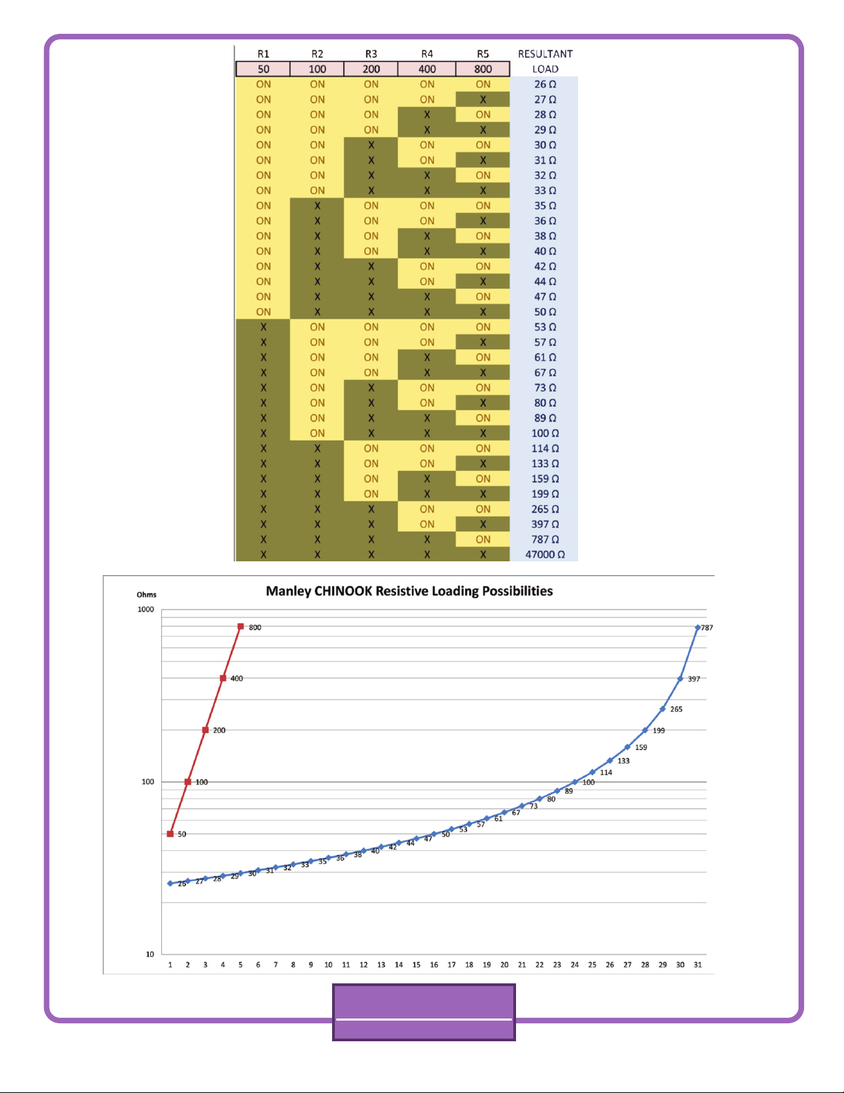
Fig 2.
MANLEY
LABORATORIES, INC.
Chinook Owners Manual 4
Page 7

LOADING, continued....
If the cartridge manufacturer specifies a load capacitance of 150 pF then it is best to subtract the cable's portion,
i.e. 90 pF. This yields a balance of 60 pF. Thus, the audition should start with the termination capacitance switches
set to 50 pF.
Each cartridge manufacturer's product will work best in a laboratory sense when terminated (loaded) with a
certain amount of resistance and capacitance. A good place to start is with those values recommended by the
cartridge manufacturer, less the interconnect cable capacitance. A good default value, if the recommended
cartridge load capacitance is unknown, is 150 pF, the sum of cable and termination capacitance switch settings.
This value reflects a de-facto standard as used by pre-amp manufacturers past and present. From there, we
encourage you to try a range of switch settings until you find those values which best suit you and your
accompanying components.
Also notice that the audible affects of varying the termination capacitance can differ substantially between
cartridge types and brands. This is to be expected due to the greatly varying source impedance characteristics of
the cartridges available today. In general, you may expect the termination capacitance value to alter, at one
extreme, subtle imaging and spatial cues, and at the other high-frequency content, forwardness and speed of the
reproduced sound. As with the load Z switch, feel free to tune the termination capacitance switches for maximum
sonic satisfaction even though the final setting differs from the cartridge manufacturer's specifications.
5. HIGH PERFORMANCE FRONT END
Your CHINOOK preamplifier makes the best use of active and passive component and circuit developments
generated over the past half-century. The hybrid cascode gain blocks simultaneously deliver wide-band high-gain,
low noise and low distortion performance without overly complex circuitry.
The multiplicative aspect of the cascode devices output (anode) impedance means that the most important
characteristics of each gain stage are preserved even though the local negative feedback used in each block is
quite small. This approach makes the amplification factor of each stage insensitive to tube gain variations due to
device production tolerance allowances or aging. In addition, a precision servo network automatically biases the
input stage to correct for device differences and component tolerances.
Other design elements include high quiescent operating currents in each gain stage. This lowers the static and
dynamic impedances found within each stage while raising the system bandwidth. This is done to insure
maximum headroom is available for the most dynamic musical performances as well as high-level pressings.
6. ACCURATE “4-CORNER” RIAA EQUALIZATION
In the spirit of high fidelity, all four RIAA phono equalization corner frequencies or time constants have been
specifically addressed in the CHINOOK preamplifier. Historically, most designs have concentrated on the “big
three” time constants of 3180, 318 and 75 microseconds. This ignores the fourth corner of about 3.2 us, which
when ignored, causes most phono stages to continue rolling off the highest octave signals coming from the phono
pickup, rather than turning the final “corner” and shelving to flat response at about 50 kHz.
As with all equalizing amplifiers intended to correct a frequency-selective emphasis curve, attention must be
given when building the inverse compensation networks. Care must be exercised if the goal is to produce a highly
accurate passive network coupled to low-feedback amplifiers. Experience has shown that the effort spent in
faithfully adhering to the inverse RIAA equalization curve produces results that easily justify the additional
procurement and manufacturing costs. To this end, only hand-selected and/or 1% tolerance components are used
throughout the RIAA equalization network. This yields impeccable inter-channel phase and gain matching.
In short, the CHINOOK will magnify the differences in the character and personality of your vinyl recording
collection, cartridge, tonearm and turntable. A microscope for the ear! Be prepared to hear previously
undiscovered musical content as you play back your favorites!
MANLEY
LABORATORIES, INC.
Chinook Owners Manual 5
Page 8

OPERATIONAL NOTES
PREPARATION FOR INSTALLATION
Budget a suitable space in which to place the preamplifier, and associated interconnect cable. This space
should be free of strong external magnetic and RF fields, and reasonably removed from strong loudspeakergenerated acoustical fields. This space should also be free of excessive heat or dust and large enough to
permit easy flow of cool air to the top, bottom and sides of the preamp.
REPLACING A TUBE
Yes there are user-servicable parts inside! But, as with other vacuum tube based products, there is also high
voltage present. Therefore caution must be used when covers are removed as there could be a shock hazard.
With all mains-powered gear make sure the power switch is off and mains cords are unplugged. If the preamp
has been powered up within the last 15 minutes stop and let the large internal capacitors finish discharging.
You will need a #1 Philips screwdriver to remove the cover. Use one hand only when reaching into the
enclosure or touching any components inside. Keep the other hand away from the preamp, preferably in your
pocket.
Increased noise level, whether gradual or abrupt, can generally be attributed to aging tubes. Gradual noise
increase from weakened tube cathode emission is the chief symptom of an aging tube, which may be
accompanied by exaggerated distortion or loss of headroom. The noise may be a variation in the level of hiss,
or the noise may develop a more granular “large-curd” quality. Should these symptoms appear, unplug the
tubes in the offending channel and replace with new devices of known-good quality. If the front-end tube is
being replaced in one channel, it is wise to replace the same tube in the alternate channel, preferably with
matching manufacturer and date code if possible.
Let the preamp tube(s) cool down, if necessary, before handling. Tube heater filaments are somewhat more
susceptible to damage when warm or hot.
Each tube should require only moderate force for removal and replacement. Gently rock the tube back and
forth a bit during removal or replacement. Avoid bending the circuit board.
tube pins prior to installation; pin misalignment will make fitting the replacement tube difficult or impossible,
and may damage the socket.
goes out in that channel, both of the tubes in that channel will go dark. If one tube is not installed, the other
tube will not light. This is akin to those old series connected xmas tree lights. So if you are trying to figure out
which tube is not working, swap one tube at a time to the other channel until the other channel dies and
sound is restored to the “bad” channel and then you will know which tube has burned out. Swap input tubes
first, and see if the problem moves. Then swap the output tubes and see if one of those is the bad guy. When
troubleshooting by substitution, remember to always only change one thing at a time!
Never substitute other type numbers of 9-pin tubes without careful research. There are literally thousands of
types that share the 9-pin mechanical basing arrangement, but NOT the internal electrical connections!
Mechanically compatible tube plugs and sockets by no means indicate electrical compatibility! And random
experimenting can easily and quickly destroy the substitute tube and other parts of your preamp!
Three tube types that are electrically and plug-socket compatible with the 6922 dual triode are the 7308,
6DJ8 and the ECC88 / E88CC. Please direct any questions to your dealer or MANLEY LABS for further
assistance: service@manleylabs.com
Notice that each channel’s tube heaters are connected in series, so if one tube
Be careful to straighten any bent
MANLEY
LABORATORIES, INC.
Chinook Owners Manual 6
Page 9

Let the preamp tube(s) cool down, if necessary, before handling. Tube heater filaments are
somewhat more susceptible to damage when warm or hot.
Each tube should require only moderate force for removal and replacement. Gently rock the tube
back and forth a bit during removal or replacement. Avoid bending the circuit board. Notice that the
heaters of the tubes of each channel are connected in series, and either channel will function if one
of the filaments is open or burned out, or unless all of the tubes are installed. Akin to those old Xmas
tree lights in the attic, no? Be careful to straighten any bent tube pins prior to installation; pin
misalignment will make fitting the replacement tube difficult or impossible, and may damage the
socket.
Never substitute other type numbers of 9-pin tubes without careful research. There are literally
thousands of types that share the 9-pin mechanical basing arrangement, but NOT the internal
electrical connections! Mechanically compatible tube plugs and sockets by no means indicate
electrical compatibility! And random experimenting can easily and quickly destroy the substitute tube
and other parts of your preamp!
Three tube types that are electrically and plug-socket compatible with the 6922 dual triode are the
7308, 6DJ8 and the ECC88 / E88CC.
Please refer to Fig. 2 for tube location.
Please direct any questions to your dealer or MANLEY LABS for further assistance:
service@manleylabs.com
MANLEY
LABORATORIES, INC.
Chinook Owners Manual 7
Page 10

Mains fuse
Keep alive fuse
RIGHT
6922
Tubes
MC
RIGHT
MM
MC
LEFT
Fig.2
MM
LEFT
6922
Tubes
Internal
View
MANLEY
LABORATORIES, INC.
Chinook Owners Manual 8
Page 11

TROUBLESHOOTING
The CHINOOK's system architecture is designed with a variety of features so as to allow flexibility in
accommodating as many cartridges and as much downstream gear as possible. Access to these
capabilities rest on the assumption that all CHINOOK systems are functioning properly. If trouble is
encountered, please review the following short list of symptoms and corrective remedies before
contacting your dealer or Manley Laboratories service.
Symptom Possible Cause Corrective Action
No lights, power Bad mains fuse Replace fuse.
Bad or unplugged power Check outlets.
cable
AC outlet not energized
Lights on, no output Open 6922 filament Check for glowing
after turn on delay 6922 Filament
Replace Tube
Hum heard when Turntable / tonearm ground wire Attach ground wire from not
connected. turntable / tonearm to
Chinook Input chassis ground terminal
on rear of CHINOOK.
Turntable cartridge close to hum Keep unit away from
fields. power transformers,
motors, etc.
Ground loop between CHINOOK Break ground connection
and turntable. of one or two of the
three system elements.
Experimentation may be
necessary.
Never operate any
equipment with an AC
“ground lifter.”
Remarks on hum pick-up: Please be aware that the CHINOOK can develop voltage amplification factors as
high as 1,000 times, or 60 dB at the 50-60 Hz power line “hum” frequencies. It is of the utmost
importance that cables handling the tiny signals from the phono cartridges be of high quality, with good
screening and connection properties, if the single-ended signal is to have any chance of being received
by the preamp reasonably free from hum and noise intrusions. This is especially true for moving coil
pickups. Please use the shortest practical interconnects and carefully route these away from all possible
electrical or magnetic hum or interference sources.
MANLEY
LABORATORIES, INC.
Chinook Owners Manual 9
Page 12

MAINS CONNECTIONS
Your CHINOOK has been factory set to the correct mains voltage for your country. The voltage setting is marked on the serial
badge, located on the rear panel. Check that this complies with your local supply.
Export units for certain markets have a molded mains plug fitted to comply with local requirements. If your unit does not have
a plug fitted the colored wires should be connected to the appropriate plug terminals in accordance with the following code:
GREEN/YELLOW - EARTH
BLUE - NEUTRAL
BROWN - LIVE
As the colors of the wires in the mains lead may not correspond with the colored marking identifying the terminals in your plug
proceed as follows:
The wire which is colored GREEN/YELLOW must be connected to the terminal in the plug which is marked by the letter E or by
the safety earth symbol or colored GREEN or GREEN and YELLOW.
The wire which is colored BLUE must be connected to the terminal in the plug which is marked by the letter N or colored
BLACK.
The wire which is colored BROWN must be connected to the terminal in the plug which is marked by the letter L or colored
RED.
DO NOT CONNECT/SWITCH ON THE MAINS SUPPLY UNTIL ALL OTHER CONNECTIONS HAVE BEEN MADE.
Note: 120 to 240VAC operation changeable with power transformer rewiring and fuse value change.
100VAC operation changeover achieved via rewiring of power transformer PCB.
Mains fuse value for 100-120V operation: 0.5A SLO-BLO
Mains fuse value for 220-240V operation: 0.25A SLO-BLO 5 x 20 mm
“Keep alive” transformer fuse for all voltage operations: 10mA MDL or MDA SLO-BLO fuse 1 x 1 1/4”
Waste Electrical and Electronic Equipment (WEEE)
Information for customers:
The European Parliament and the Council of the European Union have issued the Waste Electrical and Electronic Equipment Directive. The
purpose of the Directive is the prevention of waste of electrical and electronic equipment, and to promote the reuse and recycling and other
forms of recovery of such waste. As such the Directive concerns producers, distributors and consumers.
The WEEE directive requires that both manufacturers and end-consumers dispose of electrical and electronic equipment and parts in an
environmentally safe man-ner, and that equipment and waste are reused or recovered for their materials or energy. Electrical and electronic
equipment and parts must not be disposed of with normal household wastage; all electrical and electronic equipment and parts must be
collected and disposed of separately.
Products and equipment which must be collected for reuse, recycling and other forms of recovery are marked with the following pictogram:
Small products may not always be marked with this pictogram in which case this is present in the instructions for use, on the guarantee
certificate and printed on the packaging.
When disposing of electrical and electronic equipment by use of the collection systems available in your country, you protect the
environment, human health and contribute to the prudent and rational use of natural resources. Collecting electrical and electronic
equipment and waste prevents the potential contamination of nature with the hazardous substances which may be present in electrical and
electronic products and equipment.
5 x 20mm
Your MANLEY or LANGEVIN retailer will assist with and advise you of the correct way of disposal in your country.
MANLEY
LABORATORIES, INC.
Chinook Owners Manual 10
Page 13

SPECIFICATIONS
•Vacuum Tube Complement: 6922 x 2 (gain stage) plus 6922 x2 (output stage).
Any 6DJ8, 7308, ECC88 types may be used.
•Unbalanced Input and Output connections via Manley Teflon® & Gold plated RCA jacks
•Automatic Mute Timer: On initial power up output jacks are muted for approximately 45 seconds.
•Automatic mute circuit allows tubes to warm up and circuitry to settle.
•At power down, output jacks are immediately muted.
•Input Termination Capacitance (MM/MC): 3-position user-selectable capacitor
values of 50pF, 100pF, and 200pF. Yield resultant combinations of: 50, 100, 150, 200, 250, 300, & 350pF
•Moving Magnet Input Impedance: 47k Ohms, fixed
•Moving Coil (MC) Input Impedance: 5-position user-selectable values of 50, 100, 200,400, 800 Ohms.
which yield 32 possible loading possibilities. See chart Fig. 3
•Gain: Internal DIP switches select 45dB or 60dB
•Deviation from RIAA curve: Less than ± 0.5 dB from 20Hz to 20kHz at any gain setting.
Typically less than ±1dB from 10Hz to 100kHz.
•Distortion (THD+N) (47k Ohm Input Termination, 45dB gain, 1kHz sine, 0dBu output):
THD+N, into 100k Ohm load, BW = 100Hz-22kHz Typical 0.010%
THD+N, into 600 Ohm load, BW = 100Hz-22kHz Typical 0.030%
•Dynamic Range: 91dB @ 1kHz, 0.1% THD+N, BW = 22Hz-22kHz
107dB @ 1kHz, 1.0% THD+N, BW = 22Hz-22kHz
•Noise Floor at 45dB gain setting: -84dBu, A-weighted
•Noise Floor at 60dB gain setting: -75 dBu, A-weighted
•Output Impedance: 50 Ohms
•Internal Power Supply: Fully regulated linear B+, Heater, and control voltage rails.
•Operating Mains Voltage: Units are built for original destination country's mains voltage:
100V, 120V, or 220-240VAC as indicated on the serial number badge.
•Power Consumption: 42 watts (345mA @ 120VAC)
•Mains Voltage Frequency: 50 ~ 60Hz
•Power Transformer: Toroid construction for low radiation.
•Badge Lamp: LED illumination
•Dimensions: W=19", L=11", H=3 1/2"
•Shipping Weight: 15 Lbs.
MANLEY
LABORATORIES, INC.
Chinook Owners Manual 11
 Loading...