

Page 1
MANLEY
LABORATORIES, INC.
THE ELOP
OWNER's MANUAL
®
TUBES
brought to you by the clever folks at:
MANLEY LABORATORIES, INC.
13880 MAGNOLIA AVE.
CHINO, CA. 91710 USA
TEL: (909) 627-4256
FAX: (909) 628-2482
email: emanley@manleylabs.com
website: www.manleylabs.com
RULE
August-28-2007
Page 2

CONTENTS
SECTION PAGE
INTRODUCTION 3
FRONT PANEL 4
REAR PANEL 5
OPERATION NOTES 6 & 7
ADVANCED TRICKS 8
MAINS CONNECTIONS 9
TROUBLE SHOOTING 10 & 11
INTERNAL ADJUSTMENTS 12
SPECIFICATIONS 13
WARRANTY 14
WARRANTY REGISTRATION 15
TEMPLATE FOR USER SETTINGS 16
Page 3
INTRODUCTION
3
WARNING!
TO PREVENT THE RISK OF ELECTRIC SHOCK
DO NOT OPEN THE CABINET
REFER SERVICING TO
QUALIFIED PERSONEL
THANK YOU!...
for choosing the Manley ELOP®. This Limiter follows in the tradition of the vintage LA-2A Leveling
Amplifier using a passive electro-optical device to control gain. The advantage of a passive device
is that it eliminates the need to push the music through many transistors and/or ICs as would be the
case in a VCA based Limiter. Also like the LA-2A, the Manley utilizes a tube line amplifier for makeup gain. This is one of our favorite clean and powerful line drivers. We achieve true tube "warmth"
with fidelity rather than with distortion. Other owners of this unit love the way they can drastically
(10 dB) limit without introducing unmusical harshness. We find it extremely quick and easy to use,
mostly because it does exactly what one would expect of a good limiter when patched in. For critical
vocal tracks, this is the one to demand.
Unlike the LA-2A, we illuminate the photo-resistor with a LED rather than electroluminescent elements which are often slow and unreliable. We also use a solid state side-chain to
drive the LEDs. The Limiter also features a BYPASS switch that retains the tube section at unity gain.
Please take a few moments to read through this manual carefully as it contains information essential
to proper operation of this unit. Thank you again, and please enjoy.
GENERAL NOTES
LOCATION & VENTILATION
The Manley ELOP® must be installed in a stable location with ample ventilation. It is recommended,
if this unit is rack mounted, that you allow enough clearance on the top and bottom of the unit such
that a constant flow of air can move through the ventilation holes.
WATER & MOISTURE
As with any electrical equipment, this equipment should not be used near water or moisture.
SERVICING
The user should not attempt to service this unit beyond that described in the owner's manual.
Refer all servicing to Manley Laboratories.
!
Page 4
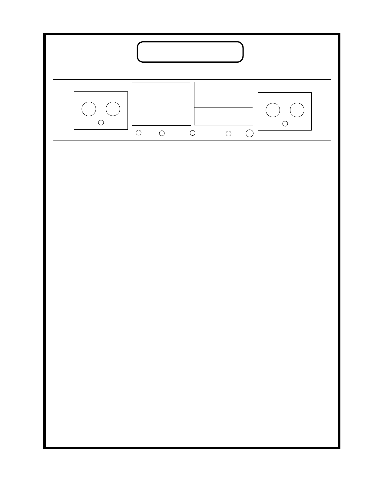
FRONT PANEL
E E
A B C D F G F H C B A
A GAIN Adjusts the gain of that audio channel. Unity gain is about the seventh marking, or 1
o'clock. Limiting usually requires some additional "make-up" gain to compare IN / BYPASS.
The Gain control can also be used as the level to tape.
B IN / BYPASS. Audio still flows through the tubes in BYPASS but at Unity Gain. Switching
to IN provides the Limiting controls and functions. Use this switch to verify that the limiting
is not messing up the original sound but enhancing it or at least leveling the volume.
C RECDUCTION Adjusts the amount of limiting in that channel. This could also be called
"threshold". Turning this clockwise introduces limiting.
D STEREO LINK / NORMAL Switching the toggle UP provides the STEREO LINK. It is
used on stereo tracks so that when either channel is called to limit, both channels reduce the
same amount at the same time. This prevents image shifts and an instrument should stay
where you panned them. Limiting individual sounds is usually done with the switch down
where each side is independent of the other.
E METER Shows the amound of gain reduction in dB from the 0 dB mark. Functions as a
high quality VU meter when the switch is set to METER OUTPUT. Note that VU meters and
PEAK meters rarely agree and that digital recorders use peak meters - Rely on those for clean
recording. VU meters are standard with analog machines and big consoles because they
correspond well with perceived loudness.
F METER SELECT Switch to REDUCTION to see the amount of limiting in dB. The wider
and quicker the reduction meter swings the more likely the limiting will be audible.
Switch to OUTPUT to show the output level as a conventional VU meter.
G POWER SWITCH Switch up to turn the unit ON. Both meters will illuminate when the
power is on.
H SIDECHAIN FILTER Allows you to limit only the frequencies above the one selected.
Useful if you want to let the bass come through full-force, but limit everything else.
4
Page 5
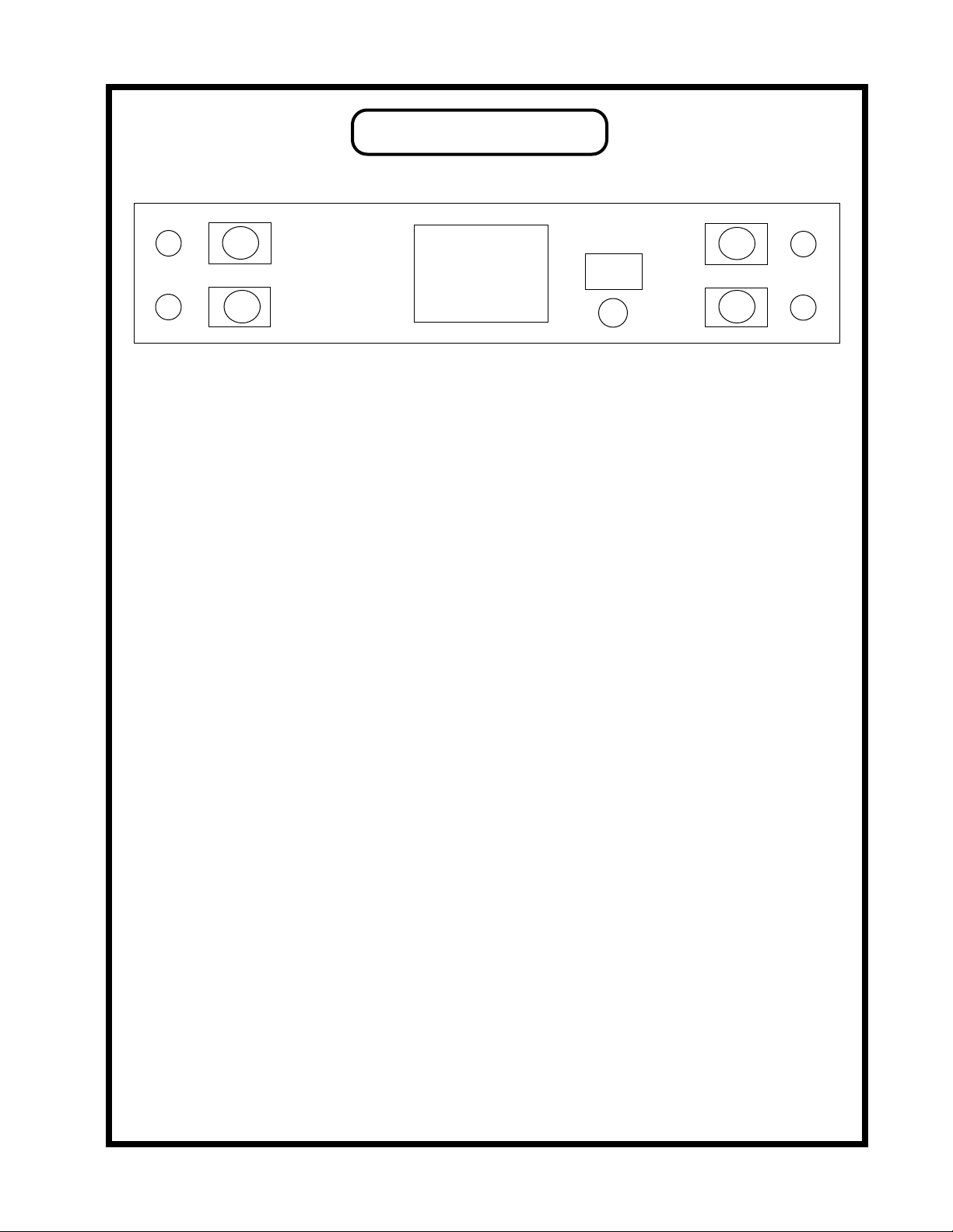
REAR PANEL
A
C
B
G
E
D
A 1/4" INPUT (UNBALANCED) (RIGHT) TIP: HOT
B XLR INPUT (BALANCED) (RIGHT) PIN 1: GROUND
C 1/4" OUTPUT (UNBALANCED) (RIGHT) TIP: HOT
D XLR OUTPUT (BALANCED) (RIGHT) PIN 1: GROUND
E IEC MAINS CONNECTOR Standard IEC mains connector for 50 /60 Hz AC.
F MAINS FUSE Replace with only a 1 Amp slo-Blo fuse.
F
SLEEVE: GROUND
PIN 2: HOT (+)
PIN 3: GROUND
SLEEVE: GROUND
PIN 2: HOT (+)
PIN 3: GROUND
I
H
J
G XLR INPUT (BALANCED ) (LEFT) PIN 1: GROUND
PIN 2: HOT (+)
PIN 3: GROUND
H 1/4"INPUT (UNBALANCED ) (LEFT) TIP: HOT
SLEEVE: GROUND
J XLR OUTPUT (BALANCED) (RIGHT) PIN 1: GROUND
PIN 2: HOT (+)
PIN 3: GROUND
K 1/4" INPUT (UNBALANCED) (RIGHT) TIP: HOT
SLEEVE: GROUND
Old versions of the ELOP® were unbalanced only. This version has both transformer (floating
!) balanced and unbalanced (transformerless) inputs. The outputs are similar, offering
transformer (floating) balanced XLR and unbalanced 1/4 jacks. The output transformers are
"driven" either way so even using unbalanced outputs there may be a part of the "character"
caused by the iron. Recording engineers tend to prefer the sound of good transformers. If done
right, they saturate a little in the deep lows and this effect "warmth" is usually attributed to
"tubes". Its the tubes that give it that clean, immediate, musical quality. Transformers give
that rich, fat bottom end - its not a "boost" like EQ but more like a low frequency "exciter".
Analog tape also saturates this way, as does the better vintage gear - tube or discrete.
5
Page 6

OPERATION NOTES
The Manley ELOP® follows certain traits and traditions established by the UREI LA-2 and
similar leveling amplifiers. These traits can be divided into two aspects - electronic and operation. The
electronic concept is simple and rather clean. Use the audio to light up LEDs or lamps which shine onto
photo-resistors. These photo-resistors, in combination with a fixed resistor, simply act as a voltage
divider to attenuate the signal. The tube line amplifier only functions to provide extra gain to make up
for attenuation losses and then acts as a fine cable driver. Simple, elegant and minimal. Operation of this
type of design is also simple, elegant and minimal. There are usually only "threshold" and "gain" controls.
Most have no user adjustment of "attack", "release", "ratio" or functions for de-essing or external
sidechains. To put it one way, the user is "stuck" with fixed time constants and a feature list that seems
utterly anemic compared to dynamic processors costing far less...
...so why are "LA" style opto-based limiters so popular? Several reasons. To paraphrase
Letterman, "The number one reason why "LA" style limiters are favorites is because.... they work right
on vocals". This "rightness" has a few aspects. The first is that "LA" style limiters don't leave much trace
of limiting as they work. This is partly due to tubes, partly to the simplicity of the opto circuit and partly
because the user can't alter the attack and release. Almost every VCA based design seems to leave
electronic personality on that critical vocal track. This is usually undesirable. Our Opto circuit has no
active limiting in the signal path. Tube circuits have the potential to be musically more transparent than
transistors because tubes are generally more linear devices. However, there are many poor examples of
tube circuits in use, and many ways to butcher the quality. We chose to use our favorite simple tube line
amplifier circuit which we also use in our Mono and Dual Mono Micpres and Enhanced Pultec Equalizers
(rather than copy UREI designs) because frankly our circuit sounds better and cleaner.
Back to this matter with fixed time constants. We get requests to modify our ELOP® for more
controls, but we get even more people raving about how great and useful the ELOP® is now. The attack,
release, knee and ratio (curve) are a function of the Vactrol Cell we chose to use. The choice was based
on the attack and release characteristics. Changing the time values in this circuit involves different
choices of Vactrols. In the VOXBOX® we spend a lot of effort to get attack and release controls and it
required a radical departure from conventional approaches. There is a major advantage to fewer controls
and a reason for the coolness of LA type limiters. You simply adjust the Threshold for the desired limiting
amount and adjust the Gain for the desired level to tape - then record. The limiter does what its supposed
to do - nothing more, nothing less. Kinda like automatically right, strangely quick and easy, and pretty
much non-distracting. We use the phrase "Set it and forget it". This is a very important feature that would
be lost with a variety of controls. A good engineer wants to be ready to record "now" and does not want
to be fussing with controls while a lead vocal is going to tape. Unfortunately most compressors drag the
engineer's attention away (and often the singer's and producer's attention away as well).
The time and slope characteristics of Opto elements are not easy to describe and probably even
more difficult to simulate. The attack is fast; not super-fast "brick wall", but fast enough to "catch"
consonants. It is also a function of level. At lower reduction levels and lower peaks the Vactrol is slower.
It becomes faster with sharp peaks and heavier levels of reduction. Release is similar but 10 to 20 times
slower. Quick peaks are handled with quick release and as gain reduction nears zero the Vactrol gets
slower like gentle braking to a stop. While normal cheapo VCA limiters are much simpler the best
approximation is 10 ms attack and 500ms release. We spec 2.5 sec for release which accounts for that
slow down near zero. The attack spec number is similarly an approximation. Who cares - it works.
6
Page 7

The slope or ratio is also difficult to simulate. The initial ratio is low and becomes higher
with more gain reduction until the LEDs light up fully and further reduction is not easy. This upper
limit of reduction is in the area of 20 dB or at the bottom of the GR meter where the ratio becomes
low again but this would be a severe setting that few engineers could use. Distortion becomes
audible at very deep limiting. In a tech shop, it is easy to drive the limiter to 20 dB of reduction and
beyond where the GR meter shows a flaw in that it "folds back". We put a higher priority on having
the meter show what the Opto was doing accurately with "normal settings" than extreme test bench
observations. Test benches don't make hit records.
So the Opto Limiters seem to be great for vocals, but what else are they used for - and what
about sounds where the time constants are less than optimum ? Historically, "LA" style limiters were
often used for bass and guitar tracks. They can be ideal for brass, saxes, synths and similar sounds
with superb results. There are other compressors that work well for these instruments but few that
are as transparent. Usually, when you hear of an engineer using a non-Opto compressor for these
instruments it is usually framed with "for the crunch" or because they add some desired color. There
are only a very small number of "clean" general purpose variable time compressors which seem to
give Opto units competition - our Variable MU® is at the top of that list. Where the "LA" style
limiters are not always appropriate is for percussion and for mixes where the percussion is just right.
The Opto typically reacts fast to peaks - fast enough to remove drums from a mix but not quite fast
enough to be called "brick wall". Individual drums tend to have a little of the initial transient let
through but the desirable tone of the drum is diminished. If used gently, this can be applied to
brighten up the attack of the drum, but it is difficult to apply in practice because drums can be very
dynamic. One great use is on the room mics. The initial drum sound is pulled down, then the natural
reverb is increased. Shades of early Led Zep. While we mentioned that "LA" style limiters are not
what we suggest for mixes, there are times when the drums are too loud or when the engineer can
mix "into" the limiter. Both techniques are possible but not necessarily easy. One trick is very little
movement on the GR meter. Some of our clients use the Opto on mixes as an effect. This application
is valid as long as the effect given and the effect desired are the same. There is not many options for
adjustment and fine tuning. The good news is that at least the Manley is clean enough to pass a good
mix. In a live sound setting the Opto will perform as a fine speaker protection device. Once again the
Threshold is set for minimal limiting with music and is just adjusted to encourage the pyrotechnician
to try harder tomorow to kill a few woofers.
Manley also offers Mastering Versions of our limiters with 1/2 dB stepped controls. We
intend to offer a second stereo opto compressor with attack and release based on the mic pre/
compressor in the VOXBOX®. Expect it to cost more than the ELOP®. Call us for details.
7
Page 8

Advanced Tricks
Here are a few tricks that are not really for rookies. They come from guys doing major records for years
and won't work unless you've mastered the basics. In other words if we gave you a Strat and Marshall it
won't make you another Jimi. Also we don't suggest that you try these out while paying big-time studio
rates - they may not be easy to get right at first. OK, you have been warned.
Trick#1. Each compressor or device in the chain has certain flavours and characteristics and with
experience we grab the ones we like because of the sound - not because "it is a compressor". The idea is to
use several cool compressors in a chain getting flavours from each depending on how much GR (gain
reduction) is used in each and how hard they are driven. It's this second concept that can be tricky. How far
to turn up each Make-up Gain to overdrive or not overdrive the next unit - and still not get flooded with
noise when the music stops. You can chain the two channels of the ELOP® and turn up the make-up of the
first channel. This works best with classic discrete and tube units and usually IC units are to be avoided.
The finesse comes from which order they are patched. See how long it might take to get best results .....
Trick#2. This one is easier but also requires serious listening. Rather than just "inserting" a limiter, try
driving the limiter from the tape patch (pre EQ), returning it to a spare fader and mixing it with the original.
So what is so tricky ? How you EQ and automate and add effects to these channels. You can also have fun
phase reversing one of the channels. You get cancellation but only at a certain level. It is sort of like gating
but different - it is a way of controlling the "ambiance".
Trick#3. Using one track to "duck" another. This may work better with compressors with attack and release
and ratio controls if you are thinking drums. Bass and vocal is very cool with the ELOP®. Set it up like
trick#2 with bass in one channel and vocal in the other (in LINK mode) and experiment with each
threshold. Two guitar tracks also work here sometimes. Obviously we pull out this trick when two tracks
are stepping on each other and EQ isn't making enough room for clarity.
Trick#4. Drive the compressor from an AUX send and return it to a channel. Once you have some limiting,
carefully turn up that aux send on the return channel to "feed back" into the limiter. Watch out for real
howling feedback and over the top limiting. If you are lucky it won't scream during the quiet parts. The key
is balancing the faders, track auxes, the return auxes, the thresholds and make-up gains. The technique can
get pretty crunchy and wild. Works best with not-so-clean compressors but is interesting with the ELOP®.
Trick#5. This one is a way to get a very good single channel De-esser from the ELOP® or other compressor
good enough for lead vocals. Mult the Insert send of the vocal to the ELOP® and to a spare channel. EQ the
snot out of that second channel -boosting the 5 or 6KHz band and chopping everything below that. Use the
insert from this channel to drive the other channel of the ELOP® but it is unlikely that you want this fader
up. Set the ELOP® to Link. The threshold of the first channel sets compression and the second channel sets
de-essing. Unlike some de-essers it will not chop highs but reduce wide-band which is less obvious. The
only drag is that the release is a little slow. Remember good de-essing is not to remove esses - the idea is to
reduce esses and make them natural sounding. BTW if you need to de-ess, you might want to re-think your
choice of gear. There are 3 main reasons we get horrible esses: 1) a gap in the singer's teeth or just a
strange voice, 2) too much or wrongly choosen EQ, or, 3) gear that distorts the highs. If the cause is "1", try
sticking some dental wax in the gap. No joke. If the cause is "2" then we can tell you some EQs allow one
to boost highs with less problems with the esses or you might try boosting a higher freq, or less during
tracking. If it is "3" you may want a better mic or sell off some of that cheap IC gear that seems to be
distorting the top in a way that you don't like. Actually we have heard some pretty expensive gear - both
tube and solid state - that has this particularly ugly distortion. If in doubt, try some tough percussion
through it like shakers or tamborines, and see how they sound...
8
Page 9

MAINS CONNECTIONS
Your ELOP® has been factory set to the correct mains voltage for your country. The voltage
setting is marked on the serial badge, located on the rear panel. Check that this complies with
your local supply.
Export units for certain markets have a moulded mains plug fitted to comply with local requirements. If your unit does not have a plug fitted the coloured wires should be connected to
the appropriate plug terminals in accordance with the following code.
GREEN/YELLOW EARTH terminal
BLUE NEUTRAL terminal
BROWN LIVE terminal
As the colours of the wires in the mains lead may not correspond with the coloured marking
identifying the terminals in your plug proceed as follows;
The wire which is coloured GREEN/YELLOW must be connected to the terminal in the plug
which is marked by the letter E or by the safety earth symbol or coloured GREEN or GREEN
and YELLOW.
The wire which is coloured BLUE must be connected to the terminal in the plug which is
marked by the letter N or coloured BLACK.
The wire which is coloured BROWN must be connected to the terminal in the plug which is
marked by the letter L or coloured RED.
DO NOT CONNECT/SWITCH ON THE MAINS SUPPLY UNTIL ALL OTHER
CONNECTIONS HAVE BEEN MADE.
Note: This unit has been factory wired for your country. If you plan to take the unit to
countries with a different mains voltage you will need to send the ELOP® to Manley Labs
for the correct power transformer - or use AC voltage converters.
9
Page 10

TROUBLE-SHOOTING
There are a number of possible symptoms of something not quite right, some may be interfacing, others we will touch
on as well. The preceding page shows that all the inputs and outputs of the ELOP® are unbalanced. No need to panic. We have
sold hundreds of these units and less than 1% ever had a problem with hum or interfacing to balanced consoles or other gear.
However if you suspect a problem the following paragraphs should help.
NO POWER, NO INDICATORS, NADA - Probably something to do with AC power. Is it plugged in? Check the fuse on
the back panel. A blown fuse often looks blackened inside or the little wire inside looks broken. A very blackened fuse is a
big hint that a short occured. Try replacing the fuse with a good one of the same value and size. If it blows too then prepare
to send the unit back to the dealer or factory for repair. The fuse is a protection device and it should blow if there is a problem.
If the unit works with a new fuse, fine. Check the MAINS VOLTAGE SELECTOR if one is fitted. Some of our models are
able to have them and some don't. It should be set correctly for your mains voltage.
LIGHTS BUT NO SOUND - First try plugging the in and out cables into some other piece of gear to verify that your wires
are OK. Next check the front panel, try BYPASS. If you have sound now it might be a good idea to turn up the output levels
to about 1 o'clock (rather than fully counterclockwise which is "minus infinity". The XLR inputs and outputs are transformer
balanced and floating. "Floating" refers to a very useful feature of transformers where they can be used without a ground
reference - this prevents ground loops before they happen rather than electronically cancel them. It does require that both PIN
2 and PIN 3 be connected (but not to each other). To interface to unbalanced units you should connect PIN 3 to Ground or
PIN 1. Brainless solution - use the 1/4" unbalanced inputs and outputs to interface to unbalanced gear.
LEVELS SEEM TO BE WRONG, NO BOTTOM - Several possible scenarios. Manley uses the professional standard of
+4 dBm = Zero VU = 1.23 volts AC RMS. A lot of semi-pro gear uses the hi-fi reference of -10 dBm = Zero VU. This is a
14 dB difference that will certainly look goofy and may tend to distort. Often there are switches on the semi-pro gear to choose
the pro reference level. We do not provide that kind of switch because of inevitable compromises in the signal path. If the
loss looks close to 6 dB and it sounds thin then one half of the signal is lost. The cause is probably wiring again. One of the
two signal carrying wires (the third is ground / shield on pin 1) is not happening. Check the cables carefully because
occasionally a cable gets modified to work with a certain unit and it seems to work but its wrong in other situations. If only
one side of the Limiter exhibits this problem, it may be a problem in the Limiter. See the next item.
ONE SIDE WORKS FINE BUT THE OTHER SIDE IS DEAD - Let's assume this is not wiring. We are pretty sure it is
the Limiter. If it were solid state you would generally send it back for repair. Being a tube unit, you can probably find the
problem and fix it in a few minutes. Not too many years ago, people could "fix" their own stuff by taking a bag of tubes down
to the corner and checking said tubes on a tube tester. These are practically extinct but no prob'. Most Manley gear is two
channel, meaning you can swap tubes to determine the bad boy. Do two at a time just watching that they are the same number.
Be careful - there are some high voltages inside the chassis and tubes can get pretty warm, but if you can replace a light bulb
you should be able to cruise through this. Before you remove a tube, just take a look at them powered up. They should glow
a bit and they should be warm. If one is not, you have already found the problem. The tube's filament (heater) is burnt out
or broken like a dead light bulb. The other big visual symptom is a tube that has turned milky white - that indicates air has
gotten into the tube, or "the vacuum leaked out". Either way, replace the tube. Call us, or look for a tube supplier on the internet.
Manley can ship you a tested one. Back to swapping - before you pull a tube, pull the power out, let the unit sit and cool and
discharge for a minute or two, then swap, then power, then check. Gentle with those tubes, don't bend the pins by trying to
insert them not quite right. A little rocking of them as you pull them out or put them in helps. When the problem follows the
tube you found the problem - a bad tube. No soldering, no meters, one screwdriver - easy.
HUM - Let's assume it knows the words. Once again - several possibilities - several cures. Most likely it is a ground loop.
The two most common procedures are: try a 3 pin to 2 pin AC adapter (about a dollar at the hardware store) which is better
than messing up the power cable by bending the ground pin until it breaks off. Method two - cutting the shield on one side
of the cable (PIN 1). This is done by some studios at every female XLR to "break" all loops. You may get a loop simply from
the rack. All the other gear in the rack is "dumping" ground noise onto the rack rails. Try removing the ELOP® from the rack
so that it is not touching any metal. You may have cured a non-loop hum. Some gear radiates a magnetic field and some gear
(especially if it has transformers) might receive that hum. A little distance was all it took. A cool method of reducing all sorts
of hum and noise is to use the new 60-0-60 balanced AC power transformers available from Equi=Tech and Furman. It costs
more but works best. Hum is more likely with the unbalanced inputs and outputs because these signals are ground referenced.
A common situation is using the limiter in a way that significantly boosts the low level signals and what may have started
out as a little hum becomes nasty. Check out the gear feeding the Manley or use less limiting and make-up gain.
10
Page 11

IT MAKES NOISES WHEN THE FRONT PANEL IS TAPPED - An easy one. Some tubes become microphonic over
time. That means they start acting like a bad microphone. Vibration has caused the supports for the little parts in the tube to
loosen and now the tube is sensitive to vibration. Easy - Replace the tube. Which one? The one that makes the most noise when
you tap it. It will have to be on , connected and speakers up but not too loud for the sake of your speakers.
IT GOT HISSY - Also easy. This is again a common tube symptom. You could swap tubes to find the culprit but an educated
guess is OK too. Generally the first tube in the path is the one with the most gain and dealing with the softest signals. The
usual suspect is the tube that is usually located closest to the front panel volume pot or the 5814 (or 12AX7, 12AT7, 12AU7,
6072 on other models). You may find that you need to choose the quietest tube out of several of that type.
DISTORTION - This might be a tube. Swapping is a good way to find out. It may be a wiring thing or mismatch as well.
Wiring problems usually accompany the distortion with a major loss of signal. Mismatches are a bit tougher. The ELOP® has
a high input impedance (HI Z) but some of our gear has a reasonably low input impedance. Without even explaining the term
"impedance" it is enough to say that a lot of gear is simply not capable of driving pro levels and low impedances. It will sound
like lost headroom, early clipping, distortion on peaks. Often changing the order of processors will do the trick. Another not
so rare place to look is the patchbay, your settings, the meter levels - it happens.
DC OR SOMETHING AT THE OUTPUT THAT IS INAUDIBLE - This might happen and it might be accompanied with
a strange hum or little whistles as it warms up. It only seems to occur with long cables. It happens on an older unit but not
on the newer one. Years ago we found a problem with our line driver section when it fed very long or cheap wire. The output
would tend to oscillate in the inaudible ultrasonic frequencies ( 200 kHz to 500 kHz) into high capacitance like a long cable.
We cured it by adding a simple 47 ohm resistor at the XLR. Newer units should not have a problem but if you have an old
one, we can FAX you a 25¢ fix. Real DC at the output would be such a rare find that we would be pretty surprised. We use
a $30 output cap to block DC. Most manufactures use a 30¢ electrolytic cap but we don't like the sound or reliability of these.
We invest more in these two output caps than most limiters spend on the entire parts list. A little very low frequency noise
might be seen at the output if you use a scope. This is generally very low level and caused by AC power fluxuations.
THE METERS ARE OUT OF CALIBRATION - If the problem only seems to be when the unit is just turned on it's normal.
It should warm up. It might be a half dB out for 15 minutes - relax. If they drift a tenth of a dB over the course of a day it is
because of bad AC power fluxuations - chances are other gear is doing worse, you just haven't found out yet. Your unit will
have been factory calibrated and tested twice before you received it. Sometimes parts drift a bit in value over the years, or
you have repaced tubes and want the unit calibrated at the same time, or you just want it as perfect as it can be. These are good
reasons to turn the page and go through the calibration procedure or sent it to a technician or the factory for a tweak. If you
send the unit to a tech, you should include this manual because they will need it. If you do it yourself, you will need an
Oscillator and a few screwdrivers and it would be nice to have a VOM meter and Scope but not necessary.
Once in a while we get a call from a client with a "digital studio" with confusion about levels. They usually start out by using
the digital oscillator from their workstation and finding pegged VU meters the first place they look and they know it can't be
the workstation. Even a -6 level from their system pegs the meters. Some of you know already what 's going on. That -6 level
is referenced to "digital full scale" and the computer might have 18 or 18.5 or 20 dB of headroom built in. That -6 level on
the oscillator is actually a real world analog +12 or +14 and those VU meters don't really go much further than +3. There are
a few standards and plenty of exceptions. One standard is that pro music (non-broadcast) VU meters are calibrated for 0VU
= +4 dBm =1.228 volts into 600 ohms. Another standard is that CDs have a zero analog reference that is -14 dB from digital
full scale or maximum. This allows sufficient peak headroom for mixed material but would be a bad standard for individual
tracks because they would likely distort frequently. This is why digital workstations use higher references like 18 and 20 to allow for peaks on individual sounds. It may be too much in some cases and too little in others. Add two other sources of
confusion. Peak meters and VU meters will almost never agree - they are not supposed to. A peak meter is intended to show
the maximum level that can be recorded to a given medium. VU meters were designed to show how loud we will likely hear
a sound and help set record levels to analog tape. By help, I mean that they can be only used as a guide combined with
experience. They are kinda slow. Bright percussion may want to be recorded at - 10 on a VU for analog tape to be clean but
a digital recording using a good peak meter should make the meter read as high as possible without an "over". Here is the
second confusion: There aren't many good peak meters. Almost all DATs have poor peak meters that do not agree with each
other. One cannot trust them to truly indicate peaks or overs. Outboard digital peak meters (with switchable peak hold) that
indicate overs as 3 (or 4) consecutive samples at either Full Scale Digital (FSD) are the best. They won't agree with VU meters
or Average meters or BBC Peak meters either. Each is a different animal for different uses. The Limiter should help digital
and analog achieve consistent levels but use each meter for it's own strength. The Reduction mode is useful with everything.
11
Page 12

INTERNAL ADJUSTMENTS
6414
12AU7WA
IC
2
1
6
4
8
1
IC
7
5
9
6414
3
12AU7WA
10
1
1) You will have to start out by setting front panel controls to these settings. BYPASS mode, SEP
(LINK OFF), REDUCTION controls counter clockwise (MIN), GAIN to 1:00 or unity, S.C. at "Flat".
The top will need to be open. There are two screws on the top that hold the top perforatedpanel to the
back. Remove these and the perforated top will slide back. Be careful! THERE ARE HIGH
VOLTAGES INSIDE THE LIMITER. DO NOT HOLD THE METAL PART OF THE
SCREWDRIVER. DO NOT PROBE AROUND WITH THE SCREWDRIVER OR FINGERS. The
unit should be on for about 15 minutes to allow for "warming up".
2 & 3) This adjusts the tube amplifier gain in all modes. 1 KHz sine at 1.23 volts RMS (+4 dBm, 0 VU) to
both inputs. BYPASS mode. Adjust 2 & 3 for unity gain at outputs.
4 & 5) This adjusts VU meter calibration for OUTPUT. Same input, Meter switches to OUTPUT. Adjust for
0 VU on the Meters.
6 & 7) This adjusts the meter zero for Reduction mode. Meter switches to REDUCTION. Adjust for 0 VU on
the Meters.
8 & 9) This adjusts the meter in Reduction mode to reflect the actual gain reduction accurately. You will
probably need to increase the oscillator 10 dB to get Limiting. Switch from BYPASS to IN. Meter
switches to OUTPUT. Adjust GAIN controls to get 0 VU on the METERS again, then adjust
REDUCTION controls to reduce the signal to -4dB. Switch METERS to REDUCTION. Adjust 8 &
9 to get -4 dB on the METERS.
10) This adjusts the gain of the right side chain and adjusts the side chain balance in Link. Switch the
LINK ON. There should be 1 to 2 dB change in the Meters. Adjust 10 so that the meter is the
same for both sides. You may have to re-adjust 8 and 9. Check that both in LINK and
SEPARATE that both channels show the same reduction.
This is a final check to verify that all adjustments are OK and the unit is ready for use. Confirm that 0
VU on the meters is +4 dBm with an external VU meter or VOM that reads between 1.22 and 1.23
volts AC and that gain reduction reads the same on OUTPUT and REDUCTION and that LINK or
UN-LINK does not reduce the gain unevenly on the two sides. Remove the power and slide the top in
all the way where it will fit into a groove in the front panel and put those two top screws back in.
Done !
12
Page 13

SPECIFICATIONS
Manley ELOP
Maximum Input (Bypass through Line Amplifier) +30 dBv
(with Limit "IN" the maximum is entirely variable)
Maximum Output +30 dBv
Headroom (referenced to +4 dBv) 26 dB
Frequency Response: 10 Hz to 70 kHz +/- 0.5 dB
THD & Noise (1kHz @ +4 dBm) .015%
Noise Floor (Gain set to minimum) -80 dB Wideband
Signal to Noise 126 dB typical
Maximum Gain 15 dB
Maximum Limiting 22 dB
®
Maximum Limiting with +4 dBm sine 15 dB
Attack Time 10 mS for 6 dB GR
Release Time 2.5 Seconds for 6 dB GR
Power Consumption .35 Amps @ 115 VAC
Fuse 1 Amp Slo-Blo
Size (2U) 19" x 3.5" x 10"
Actual Weight 11.5 Lbs
Shipping Weight 14 Lbs
Replacing Meter Bulbs: New units like this use very long-life LEDS. For older units, lamps
are available from Manley (12 volt Festoon) and available from Selco (part number 19-29-39/
12V). You remove the two small Phillips screws (back, top, center) which allows you to pull the
white light cover panel away. Gently pry out the old bulb, insert the new one and screw the
panel back on. Note that a few of the very first units used 26V lamps and if in doubt, the volts
are marked on the bulb.
13
Page 14

All Manley Laboratories equipment is covered by a limited warranty against defects in materials and
workmanship for a period of 90 days from date of purchase to the original purchaser only. A further
optional limited 5 year transferrable warranty is available upon proper registration of ownership within
30 days of date of first purchase.
Proper registration is made by filling out and returning to the factory the warranty card attached to this
general warranty statement, along with a copy of the original sales receipt as proof of the original date
of purchase, or registration can be made online in the Tech Support section of www.manleylabs.com.
This warranty is provided by the dealer where the unit was purchased, and by Manley Laboratories,
Inc. Under the terms of the warranty defective parts will be repaired or replaced without charge,
excepting the cost of tubes. Vacuum tubes and meter or badge lamps are warranted for six months
provided the warranty registration is completed as outlined above.
If a Manley Laboratories product fails to meet the above warranty, then the purchaser's sole remedy
shall be to first obtain a Repair Authorisation from Manley Laboratories and return the product to
Manley Laboratories, where the defect will be repaired without charge for parts and labour. All returns
to the factory must be in the original packing, accompanied by the Repair Authorisation, and must be
shipped to Manley Laboratories via insured freight at the customer's own expense. Factory original
packaging can be ordered from Manley Labs. Customer will be charged for new factory original
packaging if customer fails to ship product to Manley Labs in the original factory packaging. After
repair, the product will then be returned to customer via prepaid, insured freight, method and carrier to
be determined solely by Manley Laboratories. Manley Laboratories will not pay for express or
overnight freight service nor will Manley Laboratories pay for shipments to locations outside the USA.
Charges for unauthorized service and transportation costs are not reimbursable under this warranty,
and all warrantees, express or implied, become null and void where the product has been damaged by
misuse, accident, neglect, modification, tampering or unauthorized alteration by anyone other than
Manley Laboratories.
The warrantor assumes no liability for property damage or any other incidental or consequental
damage whatsoever which may result from failure of this product. Any and all warrantees of
merchantability and fitness implied by law are limited to the duration of the expressed warranty. All
warrantees apply only to Manley Laboratories products purchased and used in the USA. All
warrantees apply only to Manley Laboratories products originally purchased from an authorised
Manley dealer. Warranties for Manley Laboratories products purchased outside the USA will be
covered by the Manley Importer for that specific country or region. "Grey Market" purchases are not
covered by any warranty. In the case that a Manley Laboratories product must be returned to the
factory from outside the USA, customer shall adhere to specific shipping, customs, and commercial
invoicing instructions given with the Return Authorisation as Manley Laboratories will not be
responsible for transportation costs or customs fees related to any importation or re-exportation
charges whatsoever.
Some states do not allow limitations on how long an implied warranty lasts, so the above limitations
may not apply to you. Some states do not allow the exclusion or limitation of incidental or
consequential damages, so the above exclusion may not apply to you. This warranty gives you specific
legal rights and you may also have other rights which vary from state to state.
For Tech Support and Repair Authorisation, please contact:
MANLEY LABORATORIES, INC.
13880 MAGNOLIA AVE.
CHINO, CA. 91710 USA
TEL: (909) 627-4256
FAX: (909) 628-2482
email: service@manleylabs.com
WARRANTY
Page 15

WARRANTY REGISTRATION
We ask, grovel and beg that you please fill out this registration form and send the bottom half to:
MANLEY LABORATORIES
REGISTRATION DEPARTMENT
13880 MAGNOLIA AVE.
CHINO CA, 91710 USA
Or you may FAX this form in to: +1 (909) 628-2482 or you may fill in the online warranty
registration form found in the Tech Support section of our website www.manleylabs.com or
you can be really diligent and register your warranty three times to see if we get confused!
Registration entitles you to product support, full warranty benefits, and notice of product
enhancements and upgrades, even though it doesn't necessarily mean that you will get them (Just
kidding!) You MUST complete and return the following to validate your warranty and registration.
Thank you again for choosing Manley gear and reading all the way through The Owner's Manual.
(We really mean that sincerely, the bit about thanking you for choosing our gear. THANK YOU!!!)
MODEL MANLEY ELOP® SERIAL #__________________
PURCHASE DATE ______________ SUPPLIER ______________________
--------------------------------------------------------------------------------------------------------
PLEASE DETACH THIS PORTION AND SEND IT TO MANLEY LABORATORIES
MODEL _______________ SERIAL #__________________
PURCHASE DATE ______________ SUPPLIER ______________________
NAME OF OWNER _______________________________________________
ADDRESS ______________________________________________________
CITY, STATE, ZIP ________________________________________________
EMAIL: ________________________________________________________
TELEPHONE NUMBER___________________________________________
COMMENTS OR SUGGESTIONS?__________________________________
________________________________________________________________
Page 16

 Loading...