

Page 1

WARRANTY REGISTRATION
We ask that you please fill out this registration form and send the bottom half to:
MANLEY LABORATORIES
REGISTRATION DEPARTMENT
13880 MAGNOLIA AVE.
CHINO CA, 91710
Registration entitles you to product support, full warranty benefits, and notice of product
enhancements and upgrades. You MUST complete and return the following to validate
your warranty and registration. Thank you again for choosing Manley Laboratories.
MODEL _______________SERIALNo.______________________
PURCHASE DATE __________ SUPPLIER __________________
---------------------------------------------------------------------------------------------
PLEASE DETACH THIS PORTION AND SEND IT TO MANLEY LABORATORIES
MODEL _________________SERIAL No. __________________
PURCHASE DATE ________ SUPPLIER ___________________
NAME OF OWNER
_______________________________________________
ADDRESS
_______________________________________________
CITY, STATE, ZIP
_______________________________________________
TELEPHONE NUMBER
_______________________________________________
Serial #'s of Associated Manley Laboratories Equipment
_______________________________________________
________________________________________________________________
Page 2

WARRANTY
All Manley Laboratories equipment is covered by a limited warranty against defects in materials
and workmanship for a period of 90 days from date of purchase to the original purchaser only. A
further optional limited 5 year warranty is available to the original purchaser upon proper
registration of ownership within 30 days of date of first purchase.
Proper registration is made by filling out and returning to the factory the warranty card attached to
this general warranty statement, along with a copy of the original sales receipt as proof of the
original date of purchase. Only 1 card is issued with each unit, and the serial number is already
recorded on it.
If the warranty registration card has already been removed then this is not a new unit, and is
therefore not warranted by the factory. If you believe this to be a new unit then please contact the
factory with the details of purchase.
This warranty is provided by the dealer where the unit was purchased, and by Manley Laboratories,
Inc. Under the terms of the warranty defective parts will be repaired or replaced without charge,
excepting the cost of tubes. No warranty is offered on tubes, unless:
1. a Manley Laboratories preamplifier is used with a Manley Laboratories amplifier, and
2. the warranty registration card is filled out.
In such a case a 6 month warranty on tubes is available with the correct recording of the serial
number of the preamplifier on your warranty registration card.
If a Manley Laboratories product fails to meet the above warranty, then the purchaser's sole
remedy shall be to return the product to Manley Laboratories, where the defect will be repaired
without charge for parts and labour. The product will then be returned via prepaid, insured freight,
method and carrier to be determined solely by Manley Laboratories. All returns to the factory must
be in the original packing, (new packing will be supplied for no charge if needed), accompanied by
a written description of the defect, and must be shipped to Manley Laboratories via insured freight
at the customer's own expense. Charges for unauthorized service and transportation costs are not
reimbursable under this warranty, and all warrantees, express or implied, become null and void
where the product has been damaged by misuse, accident, neglect, modification, tampering or
unauthorized alteration by anyone other than Manley Laboratories.
The warrantor assumes no liability for property damage or any other incidental or consequental
damage whatsoever which may result from failure of this product. Any and all warrantees of
merchantability and fitness implied by law are limited to the duration of the expressed warranty.
All warrantees apply only to Manley Laboratories products purchased and used in the USA.
Some states do not allow limitations on how long an implied warranty lasts, so the above
limitations may not apply to you. Some states do not allow the exclusion or limitation of incidental
or consequential damges, so the above exclusion may not apply to you.
This warranty gives you specific legal rights and you may also have other rights which vary from
state to state.
Page 3
INPUT CONNECTIONS
A
B
C
SPDIF
SPDIF
D
AES
SPDIF
E
AES
F
UNBAL IN
BAL IN
G
AES
H
-20 LO-Z
I
UNBAL IN BAL IN
J
I UNBALANCED RCA -20dB LO-Z INPUT: User must provide his own 20dB
line stage which should include an INPUT LEVEL CONTROL into this extemely
low impedance input which is at "virtual earth" with an in line 4K resistor.
J UNBALANCED XLR INPUT: 25K "bridging" input impedance. We have
utilized the latest in op-amp design, The Linear Technology LT1028, in our
standard version of front end circuitry. The LT1028 has the lowest noise and
THD figures of any currently manufactured op-amp.
The pinout is as follows:
PIN 1 GROUND
PIN 2 HOT (+)
PIN 3 GROUND
LEFT
RIGHT
K
K BALANCED XLR INPUT: 10K "bridging" input impedance. To achieve
optimum quality from this input, ONLY A TRULY BALANCED (i.e.; fully
floating or symmetrical) drive should be employed.
The pinout is as follows:
PIN 1 GROUND
PIN 2 HOT (+)
PIN 3 LOW (-)
PLEASE NOTE: Since this input is intended for use with an electronically
balanced console output, NO means of internal level control has been provided in
this converter unit for this input.
Page 4

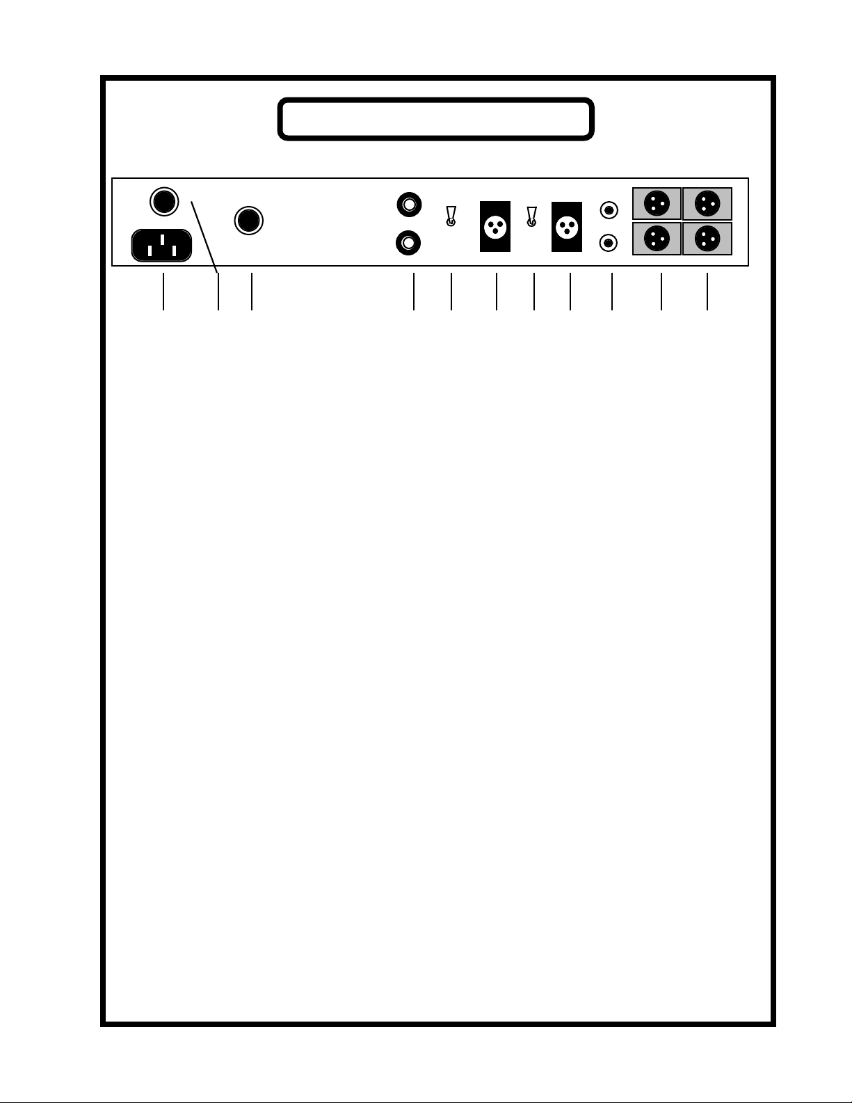
REAR PANEL
A
B
C
S/PDIF
S/PDIF
D
AES
S/PDIF
E
AES
F
UNBAL IN
BAL IN
G
AES
H
-20 LO-Z
I
UNBAL IN BAL IN
J
A IEC MAINS SOCKET: Standard IEC mains socket (120/240 VAC)
B FUSE HOLDERS: Replace with 1A SLO-BLO fuse only.
C VOLTAGE CHANGEOVER SWITCH: Set for the correct mains voltage for
your area by rotating the centre section with a flat screwdriver.
D S/PDIF DIGITAL OUTPUTS: These two Sony-Phillips Digital Interface
unbalanced digital outputs appear on UHF style jacks. BNC or RCA to UHF
adaptors are easily available if you prefer to use BNC or RCA terminated cables,
however, we believe the UHF connector is the most robust and well shielded
connector for coaxial digital links.
LEFT
RIGHT
K
E S/PDIF / AES SELECT: This LOCKING switch will optimise either AES or
SPDIF digital formats. To change the setting of this switch, PULL OUT the
toggle before switching! The MANLEY A TO D CONVERTER is standardly
shipped with two AES plus two SPDIF outputs, although any combination may
be specially ordered.
F AES DIGITAL OUTPUTS: These two AES balanced digital outputs appear on
3-pin XLR jacks. The pinout is as follows: PIN 1 GROUND
PIN 2 HOT
PIN 3 LOW
G UNBALANCED / BALANCED INPUT SELECT: This switch will select either
the unbalanced inputs OR the electronically balanced inputs. Be sure the correct
input is selected here.
Page 5

LEFT
44.1 K
48K
FRONT PANEL CONTROLS
RIGHT
ADJUST
DC OFFSET
MANLEY
ANALOGUE TO DIGITAL CONVERTER
ON
OFF
A EAB
C
D
A INPUT LEVEL-SET CONTROLS: These input attenuators function in
conjuntion with the UNBALANCED XLR INPUTS only. They are marked for left
and right channels.
B 44.1 K / 48 K SELECT: This switch will change the sampling frequency to either
44.1KHz or 48KHz. PLEASE NOTE: Power down the unit before changing
this switch. (For those who never intend to use this unit at 48KHz, we can provide
the converter hard-wried for 44.1K only.)
C DC OFFSET TRIM The DC offset trim is correctly adjusted at the factory.
However, one or two conditions can, and often do, arise that COULD require the
DC offset to be reset by the user.
One such case is if this unit is being used in an abnormally high ambient
temperature which could cause the operating temperature of this unit to rise above
its normal range. This may in turn produce a small amount of unacceptable DC
offset voltage which can easily be nulled by adjusting/ trimming the screwdriver
controls provided.
D LED: Illuminates when the power is on.
E POWER SWITCH Switch up to turn on the power, down to turn the power off.
Page 6

MAINS CONNECTIONS
Your unit has been factory set to the correct mains voltage for your country. The voltage
setting is marked on the serial badge, located on the rear panel. Check that this complies
with your local supply.
Export units for certain markets have a moulded mains plug fitted to comply with local
requirements. If your unit does not have a plug fitted the coloured wires should be connected to the appropriate plug terminals in accordance with the following code.
GREEN/YELLOW EARTH terminal
BLUE NEUTRAL terminal
BROWN LIVE terminal
As the colours of the wires in the mains lead may not correspond with the coloured marking
identifying the terminals in your plug proceed as follows;
The wire which is coloured GREEN/YELLOW must be connected to the terminal in the
plug which is marked by the letter E or by the safety earth symbol or coloured GREEN or
GREEN and YELLOW.
The wire which is coloured BLUE must be connected to the terminal in the plug which is
marked by the letter N or coloured BLACK.
The wire which is coloured BROWN must be connected to the terminal in the plug which is
marked by the letter L or coloured RED.
DO NOT CONNECT/SWITCH ON THE MAINS SUPPLY UNTIL ALL OTHER
CONNECTIONS HAVE BEEN MADE.
Page 7

INTRODUCTION
THANK YOU!...
for choosing the Manley Laboratories REFERENCE 20 BIT ANALOGUE TO DIGITAL
CONVERTER. Please read over this manual carefully as it contains information essential to
proper operation of this unit.
The MANLEY ANALOGUE TO DIGITAL CONVERTER features completely dual-mono
analogue sections and power supplies, the heart of which is the only TRUE 20-BIT, 128x
oversampling converter unit available today, custom made for us by ULTRAANALOG. By
"TRUE 20-BIT" we mean that full 20 bit perfomance IS actually achieved from years of
exhaustive research and engineering on the converter chip itself. While some converters claim
to be 20 bit, or 18 bit, or 16 bit, seldomly is the 18th, 16th, or 14th bit performance ever
reached. The 128x oversamplig rate at which the ULTRAANALOG operates eliminates the
need for anti-alias filters, and eliminates differential non-linearity and harmonic distortion for
low amplitude signals.
GENERAL NOTES
LOCATION & VENTILATION
The MANLEY ANALOGUE TO DIGITAL CONVERTER must be installed in a stable
location with ample ventilation. It is recommended, if this unit is rack mounted, that you allow
enough clearance on the top and bottom of the preamp such that a constant flow of air can flow
through the ventilation slots.
WATER & MOISTURE
As with any electrical equipment, this unit should not be used near water or moisture.
If liquid enters the unit, it must be immediately returned to your dealer for servicing.
SERVICING
The user should not attempt to service this unit beyond that described in the owner's manual.
Refer all servicing to Manley Laboratories.
WARNING!
!
TO PREVENT THE RISK OF ELECTRIC SHOCK
DO NOT OPEN THE CABINET
REFER SERVICING TO
QUALIFIED PERSONEL
Page 8

CONTENTS
SECTION PAGE
INTRODUCTION 3
MAINS CONNECTIONS 4
FIGURE 1 FRONT PANEL 5
FIGURE 2 REAR PANEL 6
INPUT CONNECTIONS 7
WARRANTY 8
WARRANTY REGISTRATION 9
Page 9

MANLEY
LABORATORIES, INC.
OWNER'S MANUAL
MANLEY REFERENCE
ANALOGUE TO DIGITAL
CONVERTER
MANLEY LABORATORIES, INC
13880 MAGNOLIA AVE.
CHINO, CA. 91710
TEL: (909) 627-4256
FAX: (909) 628-2482
 Loading...