

Page 1

0
0
Q
HI
0
-12 +12
dB
LIMIT
MAX
MIN
LIMITING
RELEASE
SLOW F
AST
OUTPUT
GAIN
-6
+4
dB
LI
MI
TE R
c
o
r
e
O/P 1 GR
O/P 2
REFERENCE
CHANNEL S
TRIP
BRICKWALL
LIMITER
DIRECT
OUT 1
MAIN
OUT 2
OUTPUT
GAIN
TUBE STAGE
EQ
INSERT
JACK
FET
MIC INPUT
LINE INPUT
DIRECT OUTPUT (1)
INSERT
PIN1: SHIELD/GROUND
PIN2: HOT/POSITIVE PHASE
PIN3: LOW/NEGATIVE PHASE
XLR PINOUT
TIP: SEND
RING: RETURN
SLEEVE: GROUND
c o r e
REFERENCE CHANNEL STRIP
REFERENCE CHANNEL ST RIP
c o r e
c o r e
c o r e
OWNER’S MANUAL
R
Page 2

Contents
i) Introduction 2
ii) Manual Conventions 2
1. Important Safety Instructions 3
2. Getting Started 3
3. Front Panel 4
4. Input Section 4
5. Optical Compressor 5
6. Equalizer 5
7. Limiter 6
8. VU Meter 6
9. Rear Panel 7-8
10. Rear Panel Connections 9
11. Operational Notes 9
12. Questions 10
13. Copyright Notice 10
14. Servicing 11
15. Core Calibration Procedure 11-12
16. Curves & Specifications 13
17. Recall Sheet 14
PAGECHAPTER
c o r e
1
Page 3

c o r e
i) An Introduction To The Manley Core Reference Channel Strip
Thank you for selecting the Manley CORE. This unit combines a high quality vacuum tube
®
microphone preamplifier, an ELOP Compressor, an EQ section and a fast FET Brickwall
Limiter.
Musical. Flexible. Forgiving.
These three concepts were my main goals in designing the CORE channel strip. To give the
musician tools he or she really needs, without needless complication.
Why is this important?
Because recording has become more complicated than ever!
Computers, plug-ins, and software can easily distract from creating your music. By designing
a dedicated recording channel with very high quality stages – but without extra functions you
will rarely use – you can concentrate on your art, not worry about the technology.
The elements that make up the CORE are the result of decades of design, listening and
experience of working with engineers and musicians. The CORE may have fewer knobs than
other units, but I think they are the right knobs.
Dave Collins
December 2013
ii) Manual Conventions
Please take a few moments to read through this manual carefully. It contains essential information
for the proper operation of your Manley Core Reference Channel Strip.
Also in the following pages you will find useful hints and tips, allowing us to help you achieve the
utmost performance from your equipment.
Below are the following conventions, used to pick out particularly important parts of the manual.
The symbols are found in the margin next to the body of text of interest.
!
Especially Useful Tip
Important Information. Read Carefully
Caution! Pay Attention!
Refer to another section in this Manual
2
Page 4

c o r ec o r e
1. Important Safety Instructions
1. Water and Moisture – Do not use The CORE near any source of water or in excessively moist
environments.
2. Object and Liquid Entry – Care should be taken so that objects do not fall, and liquids are not
spilled, into the enclosure through the openings.
3. Heat & Ventilation – When installing The CORE in a rack or any other location, be sure there is
adequate ventilation. Improper ventilation will cause overheating, and can damage the unit.
The unit should be situated away from heat sources, or other equipment that produce heat.
4. Power Sources – The CORE has a universal power supply which can operate in any country. It
has an input voltage range of 90-260 VAC at 50/60 Hz.
5. Cleaning - The CORE can be cleaned with just a damp cloth, or alcohol/methylated spirits for
more stubborn marks.
6. Damage - If after unpacking your CORE there are signs of shipping damage, contact your
dealer.
7. Servicing - Do not attempt any servicing without consulting your dealer or Manley
Laboratories, Inc. The user should not attempt to service the unit beyond that described in the
operating instructions. All other servicing should be referred to qualified service personnel.
This unit has high voltages present, even after the power has been switched off.
8. DO NOT connect the AC supply cord until all other connections have been made. Afer initial
power up the VU Meter back light will “blink” for thirty seconds. The unit remains in MUTE
until this warm up period has elapsed.
2. Getting Started
Unpacking your
The is secured in its packing carton by two end-caps.
Hold the unit by the middle and simply lift the unit vertically straight out of the box.
After it has been unpacked, check that nothing is loose inside when handling the unit. The unit is
shipped with the vacuum tubes installed. Make sure they are not loose by looking through the vent
holes on the top cover. Ensure they are standing upright in their sockets.
It is advisable to keep the original packaging. In the event of servicing or relocating, the original
packaging ensures that the unit will always be shipped safely.
This package contains the following;
1 x Manley Reference Channel Strip
1 x Manley Owner’s Manual
1 x IEC Power Cable
1 x Warranty Registration Card
1 x Warranty Statement
CORE:
CORE
CORE
CORE
3
Page 5

c o r e
3. Front Panel
c
o r e
REFERENCE CHANNEL STRIP
0
O/P
1
GR
O/P 2
LOW
0
-12
+12
dB
MAX
MIN
COMPRESSION
IN
BYP
ASS
FAST
A
TT
ACK
SLOW
F
AST
COMPRESSOR
SLOW
RELEASE
INPUT
LEVEL
MIC
MIC
FLA
T
0
180
120Hz
HI
LOW
LINE
PHANTOM
48
V
HAND
C
R
A
F
T
E
D
I
N
C
ALI
F
OR
N
IA U
SA
DIRECT
IN
FREQUENCY
100Hz-1kHz
1kHz-10kHz
-10
+10
dB
0
MIN
MAX
EQ
HI
-12
+12
dB
LI
MIT
ER
UNITY
LIMIT
MAX
LIMITING
RELEASE
SLOW
FAST
OUTPUT
GAIN
-6
+4
dB
MIN
PREAMPLIFIER
Input Attenuator
Mic/Line
Source Select
High Pass Filter
High/Low Gain
Mic 48V Phantom
Mic Phase Invert
Instrument
Direct Input
COMPRESSOR
Attack
Release
Bypass
Compression
(Threshold)
EQ
High & Low Shelf
Sweepable Mid
Frequency
Low/High Range
Select
Continuously
Variable Frequency
Selection
LIMITER
Limiting/Threshold
Release
Fast Attack FET
Brickwall Limiter
Limit LED
Indicator
Output Gain
Control
VU METER
Meter Source
Select Switch
Displays Audio;
Compressor
Gain Reduction
Tube Preamp Out
Final Output
As the signal flow in the CORE is from right to left, we'll describe the functions in that order as well:
4. Input Section
Diagram 2
INPUT
LEVEL
MIC
MIC
FLAT
0
180
120Hz
HI
LOW
LINE
P
H
A
NTO
M
48
V
HA
ND
C
RAF
T
ED
I
N
C
AL
I
FOR NI
A U
S
A
DIRECT
IN
The INPUT LEVEL control is an input attenuator. It functions like a
variable pad. It acts on the Direct In (DI), Mic and Line inputs. Fully
counter-clockwise is off, and clockwise rotation increases the level. For
the Mic input, fully clockwise represents about 40dB of gain.
With the gain switch set to LOW and the input level set fully clockwise
the MIC input will yield about 40dB of gain and the LINE input will
produce 20dB of gain.
The top label of the selector switches show operational status when the
button is pushed in and illuminated.
MIC/LINE selects either the MIC XLR input or it selects the LINE XLR or
DI 1/4 “ inputs.
The 120Hz high pass filter position is useful for reducing breath “pops,”
or any time a reduction of LOW frequencies such as train or traffic
rumble or air conditioning rumble.
The HI/LOW gain switch adds 20dB of gain to the circuit when engaged.
For most applications, this switch can be in the LOW position, but for
low output microphones or quiet sources, extra gain may be needed.
48 Volt “PHANTOM” power is applied to the Mic input XLR when this
switch is engaged. This should only be used for microphones that
require phantom power.
0 0
0 / 180 - The Mic phase switch inverts the signal by 180 degrees when
engaged.
DIRECT IN, Instrument input. This 1/4 inch input jack is for use with
guitars, keyboards, or any other instrument. When a plug is inserted
the CORE will automatically switch to the DI input. The Mic/Line switch
must be set to the Line position to activate the DI. This is an
unbalanced 10 MegOhm input that will not load down Hi Z instruments
such as a guitar. The connections on this TS Jack are TIP-HOT, SLEEVEGROUND.
!
4
Page 6
c o r e
MAX
MIN
COMPRESSION
IN
BYP
ASS
FAST
A
TT
ACK
SLOW
FAST
C
O
M
PRES
SO
R
SLOW
RELEASE
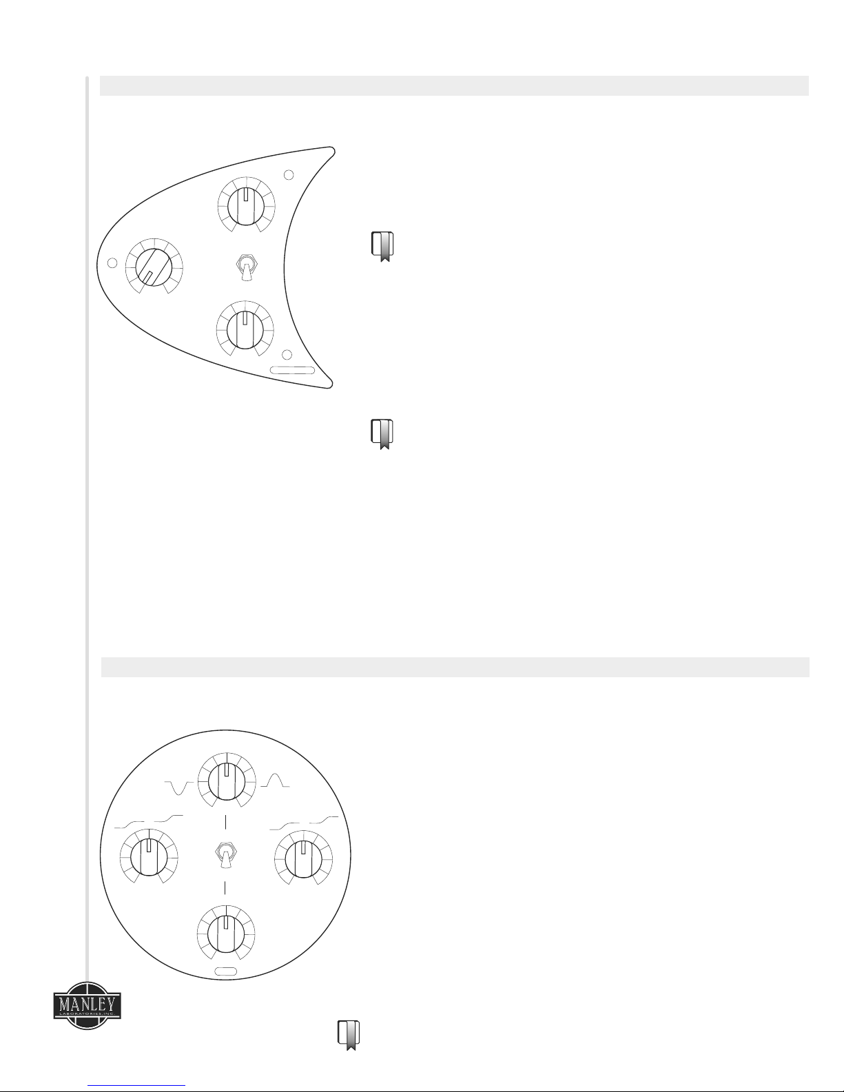
Diagram 3
The Compressor utilizes our famous circuit topology as
® ®
found in the VOXBOX , and is also similar to the ELOP and SLAM
limiters.
The COMPRESSION (Threshold) control determines at what level
the compressor begins to act. Clockwise rotation makes the
compressor reduce the signal.
With the meter in the “GR” position, the amount of gain reduction
can be displayed. (Refer to Diagram 6, pg.6)
The ATTACK control determines how long the compressor takes to
respond to signals above the threshold.
The RELEASE control determines how long the compressor takes to
recover after the signal falls below the threshold level.
The BYPASS switch can be used to bypass the compressor section.
It may be used during recording as the switching process is silent.
The output after this stage is available on XLR O/P 1 and also at
the INSERT SEND. (Refer to Diagram 7, pg.8) This audio level can
be monitored on the VU Meter.
®
ELOP
5. Compressor
®
ELOP
6. Equalizer
Diagram 4
The LOW and HI Shelf controls are Baxandall curves centered
around 90 Hz and 12kHz respectively. At 12 O’clock no
equalization is occurring. Fully CCW will reduce levels below the
center frequency to a maximum of 12dB. Fully CW will increase
levels above the center frequency to a maximum of 12dB.
The Mid Frequency EQ is a bell shaped curve, with a range
control in the low position of 100Hz to 1kHz, and in the high
position, between 1kHz and 10kHz. The desired range is selected
using the toggle switch. One can then boost or cut at the
selected frequency by approximately 10dB.
The FREQUENCY control allows continuous sweepable frequency
of the selected range so that you can TUNE IN the desired
frequency.
The controls that run vertically through the middle of the EQ
section are: MID FREQUENCY EQ, TOGGLE RANGE SWITCH, and
FREQUENCY SWEEP. These all operate together. There is
substantial overlap available between the shelf and peaking
controls, allowing a large amount of EQ control.
The EQ response curves can be seen on page 13.
FREQUENCY
100Hz-1kHz
1kHz-10kHz
0
-10
+10
dB
LOW
0
0
-12
+12
dB
MIN
MAX
E
Q
HI
-12
+12
dB
5
While compression is one of the most powerful tools
in recording, it is possible to overdo it. And, unlike
EQ, it's not reversible. Although there are really no
rules when it comes to creativity and the recording
process, a few guidelines can be helpful. When it
comes to vocals, you might not need more than a
couple dB of gain-reduction. It's better to adjust the
singing style or distance from the mic than to rely on
compression to get a totally even performance.
That said, there is no harm in really burying the GR
needle if that's the sound you're going for.
Try starting with the attack and release knobs in
the 12 O'clock position and go for a dB or three of
gain reduction. If there are still peaks that are
sounding too loud, move the attack more clockwise
to the faster settings. For percussive sounds,
starting with a faster attack can also be good.
Putting the attack and release fully clockwise and
really getting a lot of gain reduction can also
produce an interesting sound. Consider combining
a track processed this way with one done at
minimal compression.
Page 7
c o r e
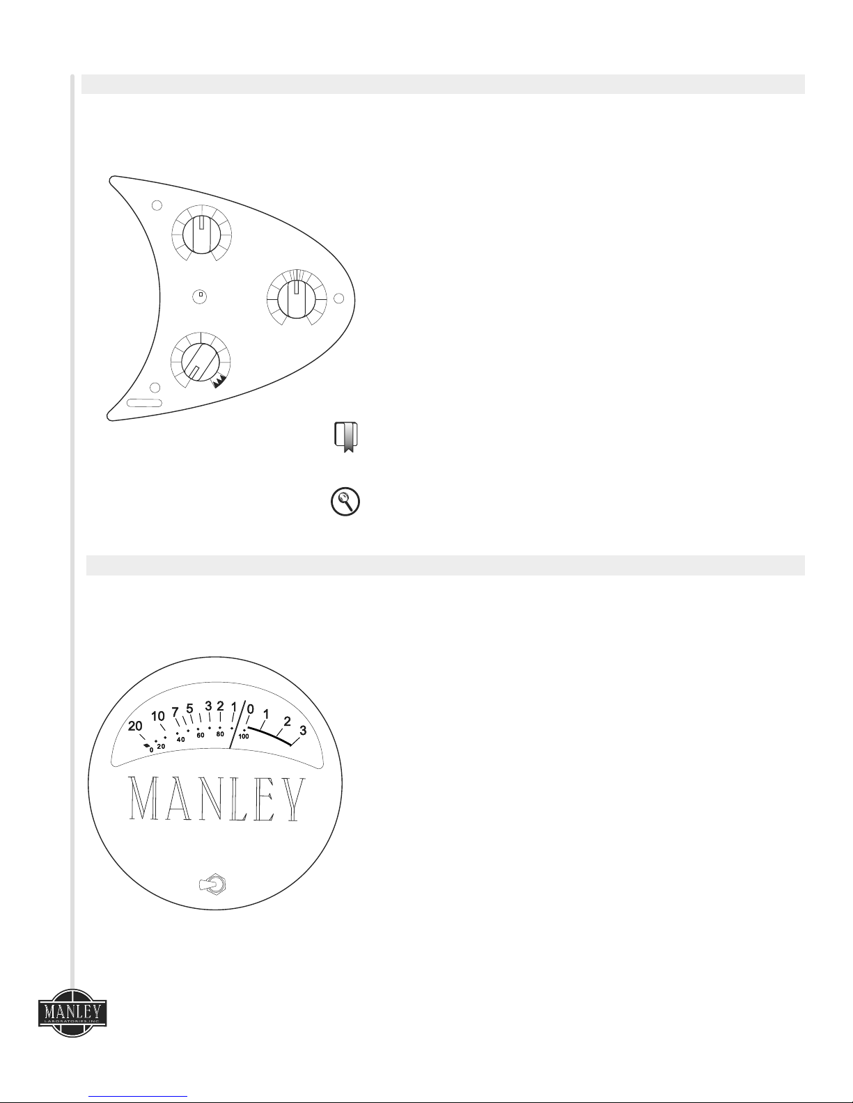
7. Limiter
Diagram 5
The FET output limiter is a powerful, high-ratio, peak limiter. It can be
used for many creative effects, as well as for setting a maximum
output ceiling to avoid overloading the next piece of gear in the chain.
The LIMITING knob controls the amount of limiting. The LIMIT LED lights
when the signal crosses the threshold, and goes off when the signal is
both below the threshold and the release time is completed.
The RELEASE controls how FAST or SLOW the limiter returns to full
volume. The
The RELEASE time control has purposely been made with a very wide
control range. Very fast release times can create a distortion effect,
this area of the RELEASE control is highlighted with a zig-zag on the
dial.
The Final OUTPUT GAIN control has a range of 10dB. This is an active
gain stage following the FET limiter that can both attenuate and
amplify the Main Output. This output is available from XLR O/P 2.
(Refer to Diagram 7, pg.7) The UNITY gain position will be within the
hash marks around the 12 o’clock area. Due to component tolerances
there may be slight variations from unit to unit.
When Limiting is set to “Minimum” the LIMIT light acts as a general
overload indicator at +20 dBu.
8. VU Meter
Diagram 6
Three positions are selectable on the analog VU meter selector switch.
O/P 1- shows the audio level of the DIRECT OUTPUT of the preamplifier
and compressor section.
O/P 2 - shows the MAIN OUTPUT audio level of the CORE.
GR - indicates the amount of COMPRESSOR gain reduction in decibels.
This position stays at “0 VU” when there is no gain reduction and
moves to the left to show the amount of compression.
Because the VU meter is mechanical and really just shows the average
level, it can't follow every signal exactly. In fact, things like snare
drums are not displayed very accurately at all. The VU meter might
only be ticking over at -10, but the actual peak level may be 20dB
higher. This is OK, as every workstation has a digital peak meter. And
it's a good idea to keep all of your peak levels in the DAW to around 6dBFS anyway. There is no reason to go to 0dBFS on the individual
tracks, and the final result will sound better and actually combine
better if the tracks are recorded with some headroom below zero.
Also, it's a good general practice to look at the VU meter occasionally
when recording and try to keep the majority of the track on the scale
of the meter – not a hard and fast rule – but if you are pinning it all the
time (unless for an intentional effect) or the needle isn't moving at all,
you might need to adjust the input gain of the CORE.
c
o
r e
O/P
1
GR
O/P
2
REFERENCE CHANNEL STRIP
6
LIMIT
MAX
MIN
LIMITING
RELEASE
SLOW
F
AST
OUTPUT
GAIN
-6
+4
dB
L
I
M
IT ER
UNITY
Page 8

MAINS VOLTAGE SHOWN ON SERIAL TAG
ELECTRIC SHOCK, DO NOT EXPOSE THIS UNIT TO RAIN OR MOISTURE CAUTION: RISK OF
ELECTRIC SHOCK. DO NOT OPEN. REFER SERVICING TO QUALIFIED PERSONNEL ONLY.
WARNING: TO REDUCE THE RISK OF FIRE OR
INSTRUMENT
IN
MIC IN
HP
FILTER
LINE IN
PHASE
DI
STAGE
LINE
STAGE
COMPRESSOR
®
ATTENUATOR
OPERATIONAL BLOCK DIAGRAM
Serial Number
MANLEY LABORATORIES INC.
13880 MAGNOLIA AVE. CHINO, CA 91710
PHONE +1 (909) 627-4256
service@manleylabs.com
www.manley.com
HANDCRAFTED IN USA
MAIN OUTPUT (2)
INPUT
LEVEL
MIC
MIC
FLAT
0
180
120Hz
HI
LOW
LINE
PHANTOM
48
V
H
ANDC
R
A
F
T
ED I
N
C
A
LIF
O
RN
I
A
U
S
A
DIRECT IN
c o r e
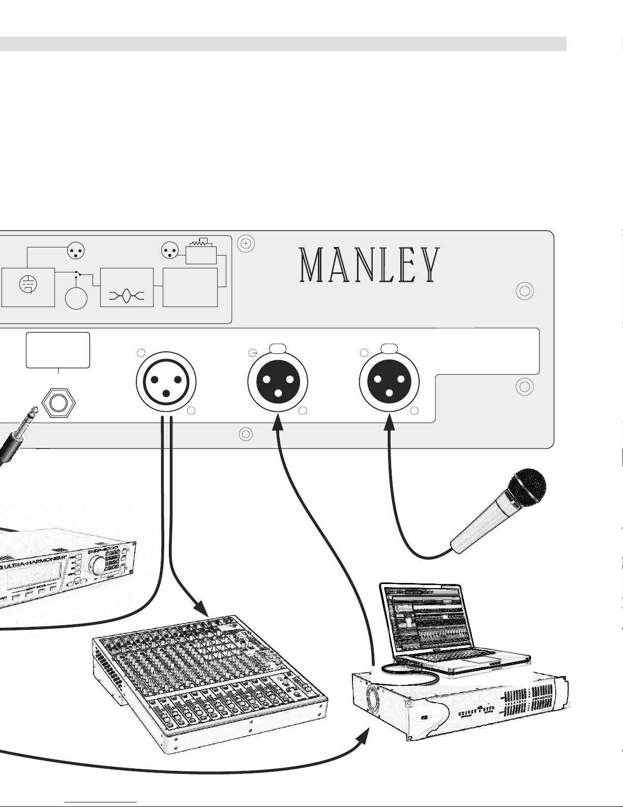
9. Rear Panel
SIGNAL PROCESSOR
EQ OR COMPRESSOR OR EFFECTS
DIRECT INPUT (FRONT PANEL)
OPTIONAL OUTBOARD
ANALOG TO DIGITAL CONVERTER
Page 9
BRICKWALL
LIMITER
DIRECT
OUT 1
MAIN
OUT 2
OUTPUT
GAIN
TUBE STAGE
EQ
INSERT
JACK
FET
PIN1: SHIELD/GROUND
PIN2: HOT/POSITIVE PHASE
PIN3: LOW/NEGATIVE PHASE
c o r e
REFERENCE CHANNEL STRIP
MIC INPUT
LINE INPUT
DIRECT OUTPUT (1)
INSERT
XLR PINOUT
TIP: SEND
RING: RETURN
SLEEVE: GROUND
MIXER
DIGITAL TO ANALOG CONVERTER
DIGITAL AUDIO
WORKSTATION
8
Diagram 7
Page 10

10. Rear Panel Connections
From Right to Left:
MIC INPUT: This is a transformer balanced, microphone input to the preamplifier.
The pinout is PIN 1: Ground, PIN 2: HOT (+), PIN 3: COLD(-).
All pins must be driven. DO NOT “float” PIN 2 or PIN 3.
LINE INPUT: An electronically-balanced, line-level input.
The pinout is PIN 1: Ground, PIN 2: HOT (+), PIN 3: COLD(-). An unbalanced source can be connected with
PIN2 or 3 grounded. Unused pins can be grounded.
®
DIRECT OUT (1): Gives an impedance balanced output directly after the tube preamp and ELOP compressor
stage. The pinout is PIN 1:Ground, PIN 2: HOT (+), PIN 3: COLD(-). An unbalanced source can be connected
with PIN2 grounded.
INSERT: This TRS 1/4” jack interrupts the connection between the PREAMP/COMPRESSOR and EQ/FET
LIMITER sections, allowing external gear to be inserted into the signal path. Alternately, it provides an input
to the CORE that is after the tube preamp, to the input of the EQ stage. The interface is unbalanced in and
out. The pinout is TIP: SEND, RING: RETURN, SLEEVE: GROUND.
OUTPUT (2): This is the main output from the CORE which is an electronically-balanced output. It is after
the EQ/Limiter section. The pinout is PIN 1: GROUND, PIN 2: HOT (+), PIN 3: COLD(-). An unbalanced source
can be connected with PIN2 or 3 floated but DO NOT ground pin 2 or 3.
c o r e
!
11. Operational Notes
Unbalanced Operation
All of the XLR inputs of the CORE can be used with either balanced or unbalanced sources. However, the Main
(2) XLR output should only be connected to balanced inputs. If it's necessary to connect to a unbalanced
input, a cable must be used that has NO connection on XLR pin 3. This is important in order to prevent
damage to the CORE, as well as distortion to the signal. DO NOT GROUND PINS 2 OR 3 on the MAIN O/P 2.
Getting the most from your CORE
Earlier, in the Introduction we mentioned one of the three design principles was “Forgiving”. We want the
CORE to be easy to use and difficult to make a bad sound! An example of this is the placement of the
compressor before the amplifier stages. This allows the signal to be reduced by the compressor first which
prevents the preamp from being overloaded. Setting the COMPRESSION level just at the start of gainreduction will allow you to get the full dynamic range of the source, but if the musician suddenly plays louder
the compressor will gracefully ride the level down.
Another forgiving element of the CORE is the FET output limiter which can be set to reduce just under the
overload level of the following piece of gear. This can be especially useful to protect an A/D converter from
overload.
There is no rule that says you can't put a line-level signal in the Mic input. Try it! Many different transformer
or tube saturation effects can be made this way.
Just be careful not to engage the PHANTOM power 48V switch if you have anything other than a phantompowered microphone plugged into the MIC INPUT.
!
!
9
Page 11

c o r e
12. Questions
Q: “Where's the -20dB pad switch?”
Because the input attenuator precedes the tube gain stage, the input level control acts as a
variable pad. It can be used to either reduce the level of a hot input signal, or to simply set
the overall gain of the preamp.
Q: “Sometimes I hear distortion in the peak limiter!”
To allow for maximum creativity, the release time of the limiter was intentionally allowed to
operate over a wide range. This means that with some signals, when the release time is set to
the fastest setting some audible distortion may be created. But not to worry, if this distortion
is not desired, just turn the release time knob counter-clockwise and slow down the release
time. The sound of a super-fast release time can be used as a creative effect. Try it on vocals or
drums! Try it on anything. You won’t damage any circuitry!
Go to www.manley.com and read our extensive FAQ for more information about the care and
feeding of vacuum tubes!
13. Notice
This manual provides general and technical information for use, installation, and operating
instructions for the Manley CORE Reference Channel Strip.
Manley Laboratories, Inc. reserves the right to make changes in specifications and other
information contained in this publication without prior notice. Manley Laboratories, Inc. shall not
be liable for errors contained herein or direct, indirect, incidental or consequential damages in
connection with the furnishing, performance, or use of this material.
No statement contained in this publication, including statements regarding suitability or
performance of products shall be considered a warranty by Manley Laboratories, Inc. for any
purpose or give rise to any liability of Manley Laboratories, Inc.
© 2014 COPYRIGHT Manley Laboratories, Inc. All rights reserved.
This manual and any associated artwork, product designs, and design concepts are subject to
copyright protection. No part of this document may be produced, in any form, without prior
written permission of Manley Laboratories, Inc.
® ® ® ®
CORE , ELOP , VOXBOX , MANLEY and the Manley Laboratories, Inc. logo are trademarks of
Manley Laboratories, Inc.
10
Page 12
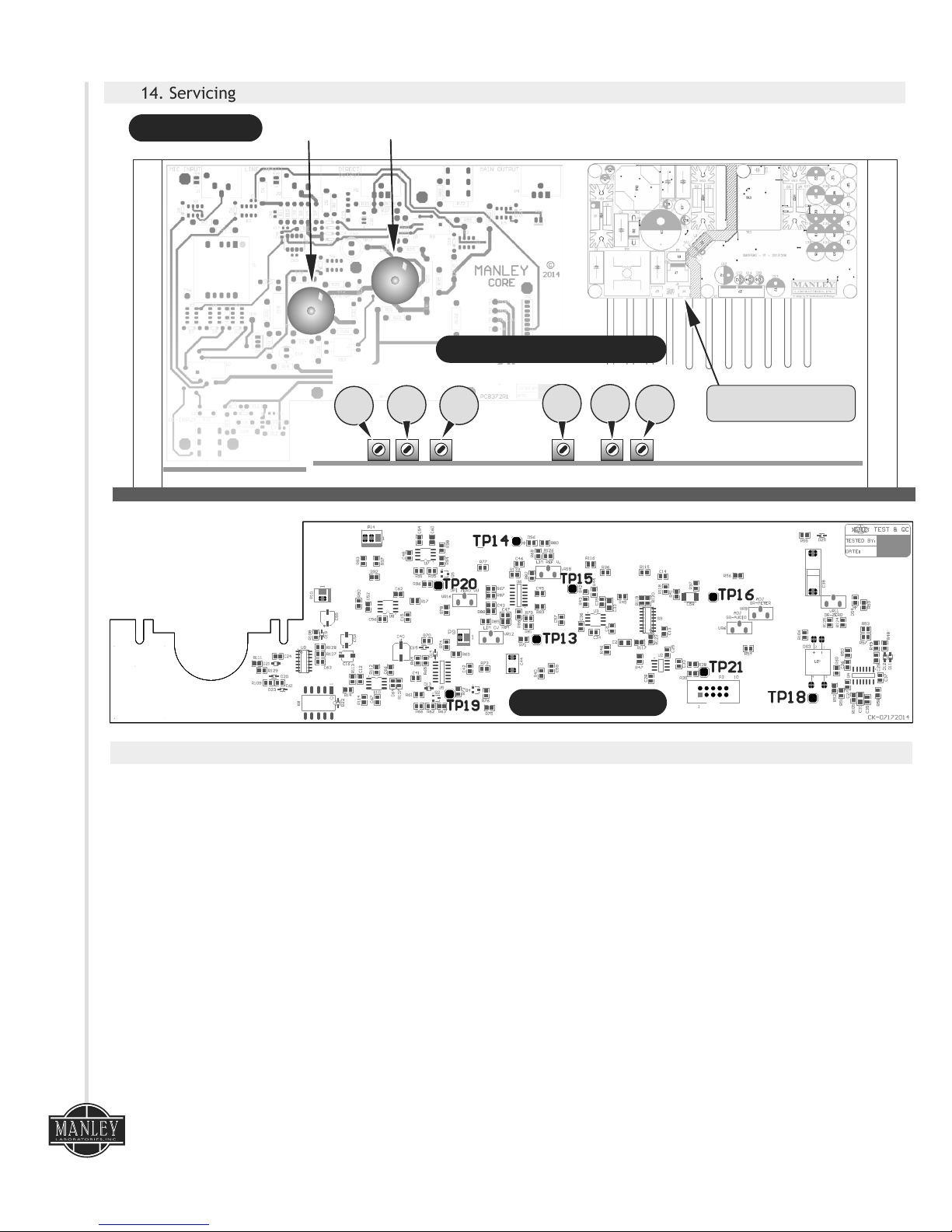
VR12
VR16
Diagram 8
Diagram 9
14. Servicing
VR11
VR9
VR6
12AX7WA
6922
TUBE LOCATION
CALIBRATION TRIM POT LOCATION
c o r e
11
TEST POINT LOCATION
VR15
GR-ZERO
GR-METER
GR-AUDIO
2 Amp Slow-Blow (T)
20mm Ceramic FUSE
LIM CV
LIM REF V
OP1 ZERO VU
15. Core Calibration Procedure
The CORE requires calibration for 3 sections of its circuitry:
I) VU METER- Adjust: +4dBu (1.228 Volts RMS) = “0” VU, Meter “GR” zero set
®
ii) ELOP COMPRESSOR - Adjust: Gain Reduction (Audio & Meter GR)
iii) FET PEAK LIMITER - Adjust: reference voltage & FET control voltage
Tools required:
- Audio Tone Generator (oscillator)
- Audio Analyzer or a voltmeter capable of reading both DC & AC voltages.
Initial settings:
- Mic/Line Input select switch: Out = LINE IN Enable
- 120Hz HP filter switch: Out = Disable
- Gain switch: Out = LOW
- 48V Phantom switch: Out = OFF
- Phase Invert switch: Out = 0
- Input Level Attenuator: Set at Minimum
- Compressor Section: Switch = Bypass; Compression = MAX, Attack & Release = FAST
- Shelving EQ section: High/Low controls set both = 12:00 o'clock.
- Mid EQ section: Boost/Cut control = 12:00 O'clock, Frequency range select switch = 100Hz-1kHz,
Frequency sweep control = MIN
- Peak Limiter section: Limiting = MIN, Release = 12:00 o'clock
- Output Gain Control: 12:00 o'clock
Page 13

c o r e
i) CALIBRATION OF VU METER:
1- Feed a balanced sine tone @ 1 KHz, +4dBu (1.228V RMS) from an audio tone
generator/oscillator into the LINE INPUT XLR.
2- Use your audio analyzer and/or, set your voltmeter to read volts AC and put it at the output of
XLR “OP1”. Star tbringing up the Input level attenuator until you have +4dBu (1.228V
RMS) at the output XLR “OP1”. This will be the same level as the input signal from oscillator
(unity gain)
3- Use the VU meter select switch to read “OP1”. Adjust VR16 (OP1 ZERO VU) so that the meter
reads “0” VU.
4- Use the VU meter select switch to read “GR”. Adjust VR11 (GR-ZERO) so meter reads “0” VU.
®
ii) CALIBRATION OF ELOP COMPRESSOR:
1- Make sure the output level at XLR “OP1” is still set for +4dBu, and the meter reading for
“OP1” is “0” VU.
2- Move your voltmeter (Volts AC)/Audio Analyzer to read the output XLR “OP2”.
3- Use the VU meter select switch to read “OP2”.
4- Adjust the OUTPUT GAIN control for an output level of +4dBu (1.228V RMS) at “OP2”. Meter
reading for “OP2” should be “0” VU.
5- Switch IN the COMPRESSOR.
6- Adjust VR6 (GR-AUDIO) for a gain reduction of 6dB at “OP2”. (The output XLR “OP2” will read
-2 dBu).
7- Use the VU meter select switch to read “GR”.
8- The VU meter should read -6. If not, adjust VR9 (GR-METER). Verify that VU “GR” and audio
are within 0.2dB of each other.
9- Repeat steps 6 to 8.
10- Switch out the COMPRESSOR by switching it to BYPASS.
iii) CALIBRATION OF PEAK LIMITER:
1- Make sure the output level at XLR “OP2” is still reading +4dBu, and the meter reading for
“OP2” is “0” VU.
2- Turn OFF your audio generator/oscillator temporarily to complete next step.
3- Switch your voltmeter to read Volts DC. Locate test point TP13 on the front panel PCB and use
your voltmeter to check for a voltage reading of +9.0VDC (± 0.1VDC). Adjust VR15
(LIM REF V.) So that TP13 reads 9.0 VDC. Locate test point TP14 verify a voltage reading of -
9.0Vdc (± 0.1VDC).
4- Locate test point TP20. Check for a reading of -4.4VDC (± 0.3Vdc), Adjust VR12 (LIM CV) so
that TP20 = -4.4 VDC
5- Turn audio generator/oscillator back on.
6- Make sure the output level at XLR “OP2” is still +4dBu, and the meter reading for “OP2” is “0”
VU.
7- Move the limiting control to “MAX”. Peak limiter red LED indicator should turn ON (± 1.0dB).
Decrease oscillator output level by 2dB. The LED indicator should turn OFF.
8- Return the limiting control back to “MIN”. Restore oscillator output level back to +4dBu.
9- Use the VU meter select switch to read “GR”.
10- Increase the oscillator output to +21dBu. The Peak limiter red LED indicator should turn ON
(±1.5db). Decrease oscillator output level by 2dB. The LED indicator should turn OFF.
Note-1: if you do not have enough output level coming from your oscillator, then increase the signal level
coming into the CORE by adjusting the INPUT LEVEL ATTENUATOR control. Bring up the input level
attenuator until you have a reading of +21dBu at the output XLR “OP2”.
Note-2: The Manley CORE Peak limiter section was designed to automatically “kick in” according to
specific output levels at the main output “OP2”.
When the LIMITING control knob is set at MIN the LIMIT threshold will be at +20dBu (± 1dB)
When the LIMITING control knob is set at MAX the LIMIT threshold will be at +3.5dBu (± 0.5dB)
12
Page 14
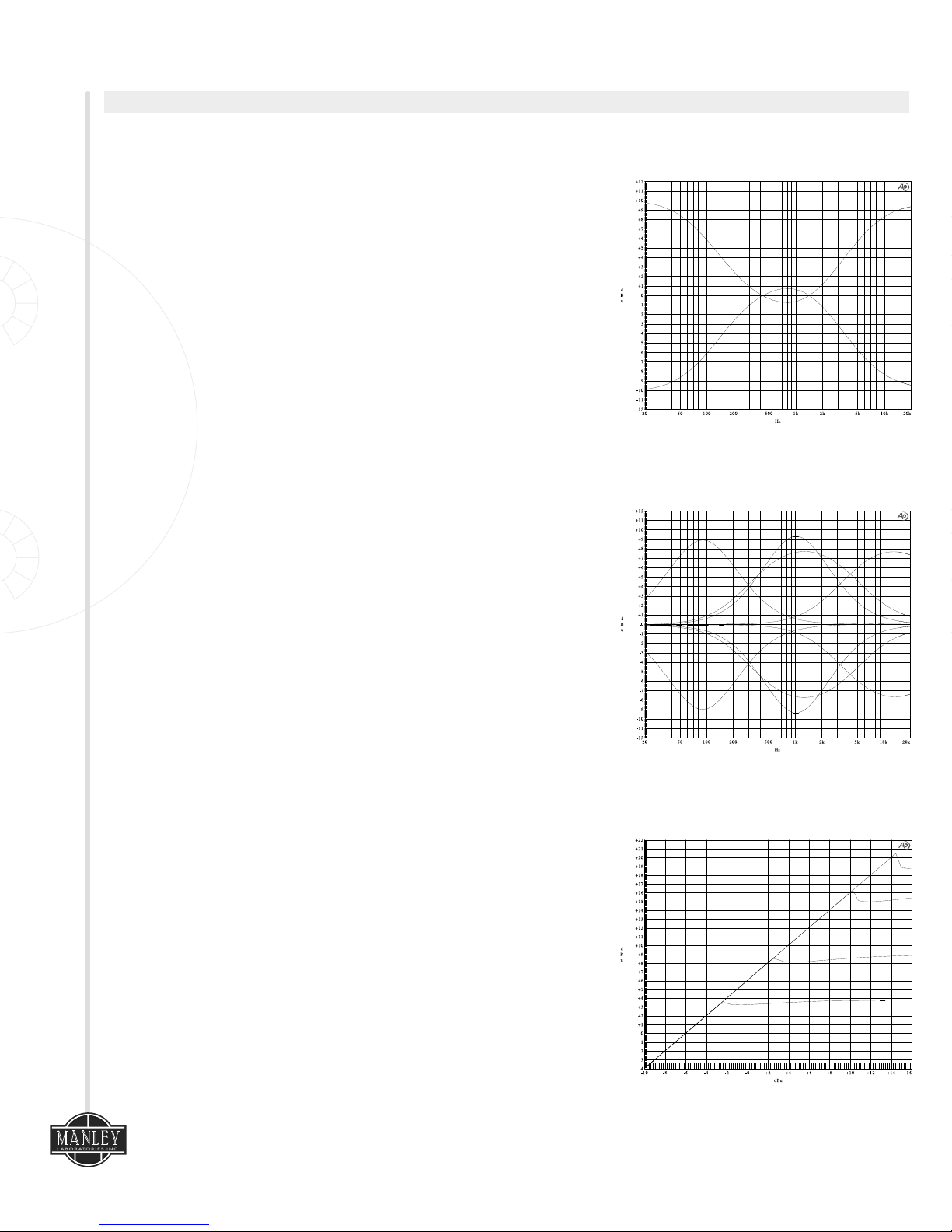
16. Curves & Specifications
c o r e
13
MID EQ PLOT
15
LIMITER, MIN, MED, MAX
EQ SHELF
Ÿ ALL-TUBE preamplifier audio path using 1 x 12AX7WA for gain and 1 x 6922 White Follower
Ÿ Balanced Transformer Coupled XLR Microphone Input Impedance: 1250 Ohms
Ÿ Balanced XLR Line Input Impedance: 10 kOhms
Ÿ Unbalanced 1/4" Direct Input Impedance: 10 Meg Ohm
Ÿ Hi-current drive Direct Output Impedance: 50 Ohms
Ÿ Silent conductive plastic INPUT attenuator
Ÿ Compressor Maximum GAIN REDUCTION: 16 dB
Ÿ Compressor ATTACK time:
60ms slowest CCW, 30ms at 12:00, 5ms fastest CW for 6dB compression
Ÿ Compressor RELEASE time:
1.5s slowest CCW, 1s at 12:00, 100ms fastest CW from 6dB compression
Ÿ Limiter ATTACK time: 115μs
Ÿ Limiter RELEASE time:
300 ms slowest CCW, 150 ms at 12:00, 2.3 ms fastest CW
Ÿ Maximum Input Mic input (Low Gain Setting): -5 dBu or 435mV RMS @ 0.5% THD
Ÿ Maximum Input Mic input (High Gain Setting): -25 dBu or 44mV RMS @ 0.5% THD
Ÿ Maximum Input Line input (Low Gain Setting): +13 dBu or 3.5V RMS @ 0.5% THD
Ÿ Maximum Input Line input (High Gain Setting): -8 dBu or 300mV RMS @ 0.5% THD
Ÿ Maximum Input Direct input (Low Gain Setting): +24 dBu or 12V RMS @ 0.5% THD
Ÿ Maximum Input Direct input (High Gain Setting): +17 dBu or 5.5V RMS @ 0.5% THD
Ÿ Maximum Input Insert return: +20 dBu or 7.8V RMS @ 0.5% THD
Ÿ Maximum Preamp Output (Insert Send): +35 dBu or 43V RMS @ 0.5% THD
Ÿ Maximum Preamp Output (Insert Send): +22 dBu into 600 Ohms
Ÿ Maximum Main Output: +20 dBu
Ÿ Insert Send output impedance: 50 Ohms
Ÿ Insert Return input impedance: 13 kOhms
Ÿ Main Output Impedance: 50 Ohms
Ÿ Direct Output Headroom (referenced to +4 dBv): 31 dB
Ÿ Main Output Headroom (referenced to +4 dBv): 16 dB
Ÿ Dynamic Range: >90 dB
Ÿ Frequency Response: 10 Hz to 20 kHz ±0.5 dB
Ÿ Large LED illuminated VU METER
Ÿ Meters switch to read Direct Output (1) from preamp, Output (2) from Main Out,
or Compressor Gain Reduction
Ÿ THD & Noise (1kHz @ +4 dBm): 0.02% at Low Gain setting
Ÿ Noise Floor (Gain set to minimum): -70 dB wideband typical
Ÿ Gain via Microphone Input: 40 or 60 dB
Ÿ Gain via Line Input: 20 or 40dB
Ÿ Maximum Gain of EQ & Limiter section: 10 dB
Ÿ AUTOMUTE warmup delay: 30 seconds
Ÿ Power consumption: 35 Watts
Ÿ Operating mains voltage: 90 to 254 VAC (internal universal supply)
Ÿ Mains Voltage Frequency: 50~60Hz
Ÿ Dimensions: 19" x 3 ½" x 7" (occupies 2u)
Ÿ Unit weight: 8.3 lbs.
Ÿ Shipping weight: 11.5 lbs.
Page 15

c o r e
14
17. Recall Sheet
ARTIST
SONG
INSTRUMENT / TRACK
MIC NOTES
DATE
ENGINEER
ARTIST
SONG
INSTRUMENT / TRACK
MIC NOTES
DATE
ENGINEER
c o
r
e
REFERENCE
CHANNEL S
TRIP
0
O/P
1
GR
O/P
2
LOW
0
-12
+12
dB
MAX
MIN
COMPRESSION
IN
BYPASS
F
AST
ATTACK
SLOW
F
AST
C
OMP
R
E
S
SOR
SLOW
RELEASE
INPUT
LEVEL
MIC
MIC
FLA
T
0
180
120Hz
HI
LOW
LINE
PHANTOM
48
V
H
A
N
DCRAF
TE
D
I
N CA
LI
FO
RNIA
U
SA
DIRECT
IN
FREQUENCY
100Hz-1kHz
1kHz-10kHz
-10
+10
dB
0
MIN
MAX
EQ
HI
-12
+12
dB
L
I
MI
T
ER
UNITY
LIMIT
MAX
LIMITING
RELEASE
SLOW
F
AST
OUTPUT
GAIN
-6
+4
dB
MIN
c
o
r
e
REFERENCE
CHANNEL S
TRIP
0
O/P 1
GR
O/P 2
LOW
0
-12
+12
dB
MAX
MIN
COMPRESSION
IN
BYPASS
F
AST
ATT
ACK
SLOW
F
AST
COM
P
RES
S
O
R
SLOW
RELEASE
INPUT
LEVEL
MIC
MIC
FLA
T
0
180
120Hz
HI
LOW
LINE
PHANTOM
4
8
V
HA
ND
CR
A
FT
ED IN
CA
LI
F
ORNI
A USA
DIRECT
IN
FREQUENCY
100Hz-1kHz
1kHz-10kHz
-10
+10
dB
0
MIN
MAX
E
Q
HI
-12
+12
dB
L
I
M
IT
ER
UNITY
LIMIT
MAX
LIMITING
RELEASE
SLOW
F
AST
OUTPUT
GAIN
-6
+4
dB
MIN
Page 16

MAX
MIN
COMPRESSION
IN
BYP
ASS
FAST
ATT
ACK
SLOW F
AST
C
O
M
PRESSO
R
SLOW
FREQUENCY
100Hz-1kHz
1kHz-10kHz
0
-10 +10
dB
LOW
0
-12
+12
dB
MIN
E
Q
RELEASE
INPUT
LEVEL
MIC
FLA
T
0
180
120Hz
HI
LOWLINE
P
HANT
O
M
48V
RAF
TE
D I
N
C
A
LI
F
ORNIA U
S
A
DIRECT
IN
MANLEY LABORATORIES INC.
13880 MAGNOLIA AVE. CHINO, CA 91710
PHONE +1 (909) 627-4256
service@manleylabs.com
www.manley.com
MAINS VOLTAGE SHOWN ON SERIAL TAG WARNING: TO REDUCE THE RISK OF FIRE OR
ELECTRIC SHOCK, DO NOT EXPOSE THIS UNIT TO RAIN OR MOISTURE CAUTION: RISK OF
ELECTRIC SHOCK. DO NOT OPEN. REFER SERVICING TO QUALIFIED PERSONNEL ONLY.
INSTRUMENT
IN
MIC IN
HP
FILTER
LINE IN
PHASE
TUBE STAGE
DI
STAGE
LINE
STAGE
COMPRESSOR
®
ATTENUATOR
MAIN OUTPUT (2)
OPERATIONAL BLOCK DIAGRAM
HAND CRAFTED IN USA
SERIAL No.
Rev. 2.0 ZF 2014
Designed & Handcrafted in USA
Manley Laboratories, Inc.
13880 Magnolia Avenue
Chino, CA 91710 USA
T: +1 (909) 627-4256
www.manley.com
 Loading...