

Page 1
M SERIES
M-15/45/90 Ice Dispensers
INSTALLATION & SERVICE GUIDE
Part Number 5011634
Manitowoc Beverage Equipment
2100 Future Drive Sellersburg, IN 47172-1868
Tel: 812.246.7000, 800.367.4233 Fax: 812.246.9922
www.manitowocbeverage.com
In accordance with our policy of continuous product development and
improvement, this information is subject to change at any time without notice.
March 23, 2005 REV1
Page 2

FOREWORD
Manitowoc Beverage Equipment (MBE) developed this manual as a reference guide for the owner/
operator , service agent, and installer of this equipment. Please read this manual before installation
or operation of the machine. A qualified service technician should perform installation and startup of this equipment, consult the Troubleshooting Guide within this manual for service assistance.
If you cannot correct the service problem, call your MBE Service Agent or Distributor . Always have your model and
serial number available when you call.
Your Service Agent___________________________________________________________________
Service Agent Telephone Number ______________________________________________________
Your Local MBE Distributor ___________________________________________________________
Distributor Telephone Number _________________________________________________________
Model Number ______________________________________________________________________
Serial Number _______________________________________________________________________
Installation Date _____________________________________________________________________
UNPACKING AND INSPECTION
Note: The unit was thoroughly inspected before leaving the factory. Any damage or irregularities should
be noted at the time of delivery.
WARRANTY INFORMATION
Consult your local MBE Distributor for terms and conditions of your warranty. Your warranty specifically
excludes all beverage valve brixing, general adjustments, cleaning, accessories and related servicing.
Your warranty card must be returned to Manitowoc Beverage Equipment to activate the warranty on this
equipment. If a warranty card is not returned, the warranty period can begin when the equipment leaves
the MBE factory .
No equipment may be returned to Manitowoc Beverage Equipment without a written Return Goods
Authorization (RGA). Equipment returned without an RGA will be refused at MBE’ s dock and returned to
the sender at the sender’s expense.
Please contact your local MBE distributor for return procedures.
Page 3

TABLE OF CONTENTS
FOREWORD ........................................................................................................ 2
UNPACKING AND INSPECTION ........................................................................2
WARRANTY INFORMA TION ............................................................................... 2
SAFETY ...............................................................................................................5
IMPORT ANT SAFETY INSTRUCTIONS ............................................................................. 5
CARBON DIOXIDE WARNING........................................................................................... 5
QUALIFIED SERVICE PERSONNEL .................................................................................. 5
SHIPPING , STORAGE, AND RELOCATION....................................................................... 5
ADDITIONAL WARNINGS ................................................................................................. 5
GROUNDING IN STRUCTIONS ......................................................................................... 6
INSTALLATION.................................................................................................... 7
COUNTER TOP INST ALLA TION........................................................................................ 7
DRAINAGE OPTIONS ....................................................................................................... 7
OPERATION ........................................................................................................ 8
UNIT INSPECTION ............................................................................................................ 8
ICE RECOMENDED FOR DISPENSING ............................................................................. 8
ICE STORAGE AND DISPENSING .................................................................................... 8
PUSH LEVER ICE DISPENSING........................................................................................ 8
PUSH BUTTON ICE DISPENSING..................................................................................... 8
BEVERAGE SYSTEM ........................................................................................................ 8
SPECIFICA TIONS ............................................................................................................. 9
AGIT ATION TIMER ........................................................................................................... 11
DOOR............................................................................................................................... 11
BIN FLOW RESTRICTOR & ICE FLOW............................................................................12
GEAR MOTOR REMOV AL................................................................................................12
Page 4

TABLE OF CONTENTS
USER MAINTENANCE ......................................................................................13
CLEANING AND SANITIZING ...........................................................................................13
EXPLODED VIEWS, PARTS & DIAGRAMS .....................................................14
M-15A/15B/45/90 ST ANDARD ALL VOL T AGES ................................................................14
M-15C ST ANDARD ALL VOL T AGES ................................................................................14
M-15C WITH AGIT A TION TIMER ......................................................................................15
M-90 WITH LIGHTS AND VAL VES ALL VOL TAGES ........................................................15
M-15 EXPLODED VIEW (TOP) .........................................................................................16
M-15 EXPLODED VIEW (BASE) .......................................................................................17
M-15 A EXPLODED VIEW (FRONT)..................................................................................18
M-15 B EXPLODED VIEW (FRONT)..................................................................................19
M-15 C EXPLODED VIEW (FRONT)..................................................................................20
M-45/90 EXPLODED VIEW (BASE)...................................................................................21
M-45/90 EXPLODED VIEW (FRONT) ................................................................................23
M-90 EXPLODED VIEW (FRONT) .....................................................................................25
TROUBLESHOOTING....................................................................................... 27
INDEX ................................................................................................................ 31
Page 5
Installation and Service Manual
SAFETY
IMPORTANT SAFETY INSTRUCTIONS
Carefully read all safety messages in this manual. Learn how to operate the SV unit properly . Do not
allow anyone to operate the unit without proper training and keep it in proper working condition.
Unauthorized modifications to the SV may impair function and/or safety and affect the life of the unit.
CARBON DIOXIDE WARNING
DANGER: Carbon Dioxide (CO2) displaces oxygen. Exposure to a high concentration of CO2 gas causes
tremors, which are followed rapidly by loss of consciousness and suffocation. If a CO2 gas leak is
suspected, particularly in a small area, immediately ventilate the area before repairing the leak. CO2 lines
and pumps should not be installed in an enclosed space. An enclosed space can be a cooler or small
room or closet. This may include convenience stores with glass door self serve coolers. If you suspect CO
may build up in an area, venting of the B-I-B pumps and / or CO2 monitors should be utilized.
QUALIFIED SERVICE PERSONNEL
WARNING: Only trained and certified electrical and plumbing technicians should service this unit. All
wiring and plumbing must conform to national and local codes.
2
SHIPPING, STORAGE, AND RELOCATION
CAUTION: Before shipping, storing, or relocating this unit, syrup systems must be sanitized. After
sanitizing, all liquids (sanitizing solution and water) must be purged from the unit. A freezing environment causes residual sanitizing solution or water remaining inside the unit to freeze, resulting in
damage to internal components.
ADDITIONAL WARNINGS
Installation and start-up of this equipment should be done by a qualified service technician. Operation,
maintenance, and cleaning information in this manual are provided for the user/operator of the equipment.
Save these instructions.
5
Page 6

SAFETY
GROUNDING IN STRUCTIONS
WARNING: Risk of electrical shock. Connect to a properly grounded outlet only .
This appliance must be grounded. In the event of malfunction or breakdown, grounding provides a
path of least resistance for electric current to reduce the risk of electric shock. This appliance is
equipped with a cord having an equipment-grounding conductor and a grounding plug. The plug
must be plugged into an appropriate outlet that is properly installed and grounded in accordance
with all local codes and ordinances.
DANGER – Improper connection of the equipment-grounding conductor can result in a risk of electric shock. The conductor with insulation having an outer surface that is green with or without yellow
stripes is the equipment grounding conductor. If repair or replacement of the cord or plug is necessary , do not connect the equipment-grounding conductor to a live terminal. Check with a qualified
electrician or serviceman if the grounding instructions are not completely understood, or if in doubt
as to whether the appliance is properly grounded. Do not modify the plug provided with the appliance – if it will not fit the outlet, have a proper outlet installed by a qualified electrician.
WARNING – When using electric appliances, basic precautions should always be followed, including the following:
a)Read all the instructions before using the appliance.
b)T o reduce he risk of injury , close supervision is necessary when an appliance is used near
children.
c)Do not contact moving parts.
d)Only use attachments recommended or sold by the manufacturer .
e)Do not use outdoors.
f) For a cord-connected appliance, the following shall be included:
• Do not unplug by pulling on cord. T o unplug, grasp the plug, not the cord.
• Unplug from outlet when not in use and before servicing or cleaning.
• Do not operate any appliance with a damaged cord or plug, or after the appliance
malfunctions or is dropped or damaged in any manner . Return appliance to the nearest
authorized service facility for examination, repair , or electrical or mechanical adjustment.
g)For a permanently connected appliance – Turn the power switch to the off position when
the appliance is not in use and before servicing or cleaning.
h) For an appliance with a replaceable lamp – always unplug before replacing the lamp.
Replace the bulb with the same type.
i) For a grounded appliance – Connect to a properly grounded outlet only. See Grounding
Instructions.
SAVE THESE INSTRUCTIONS
Page 7
INSTALLATION
COUNTER TOP INSTALLATION
Check the equipment location. Assure the proper drain and
electrical requirements are available before proceeding.
Carefully remove the dispenser from the shipping carton.
If the dispenser is to be set on legs, lay the dispenser on its’
back. Use the shipping cardboard as a protective interface
between the dispenser and the floor. Thread the legs into
the leg gussets on the bottom corners of the dispenser. If
the dispenser is to be set on a counter without the legs,
most local codes require the dispenser to have a silicone
seal between the counter and the dispenser.
Carefully pick up the dispenser, setting it in place. Be sure
the dispenser is stable and level. Place a level on the top of
the bin, side to side and front to back to see if the bin is
level. If the dispenser has legs, level the dispenser bin by
adjusting the dispenser legs. If the dispenser does not have
legs, shim between the counter top and the dispenser.
Remove the splash panel and drain pan from the front of
the dispenser. If your dispenser has beverage valves at-
Installation and Service Manual
tached, these valves will be attached to the splash panel.
Included inside the dispenser from the factory is a length
(1.8m [6ft.]) of vinyl tubing. One half of this tubing is to be
used for the bin drain, with the other half of the tubing used
for the drain pan drain. Att ached to the tubing are two tubing adaptors.
If beverage valves are supplied with your dispenser, connect them to the beverage system at this time according to
the information supplied by the beverage supplier.
Route the electric wires under the dispenser and out to the
electrical receptacle.
Replace the drain pan to the dispenser. Secure the free
ends of the vinyl drain tubing to the drain connections supplied by the owner/operator. Attach the splash panel to the
front of the dispenser.
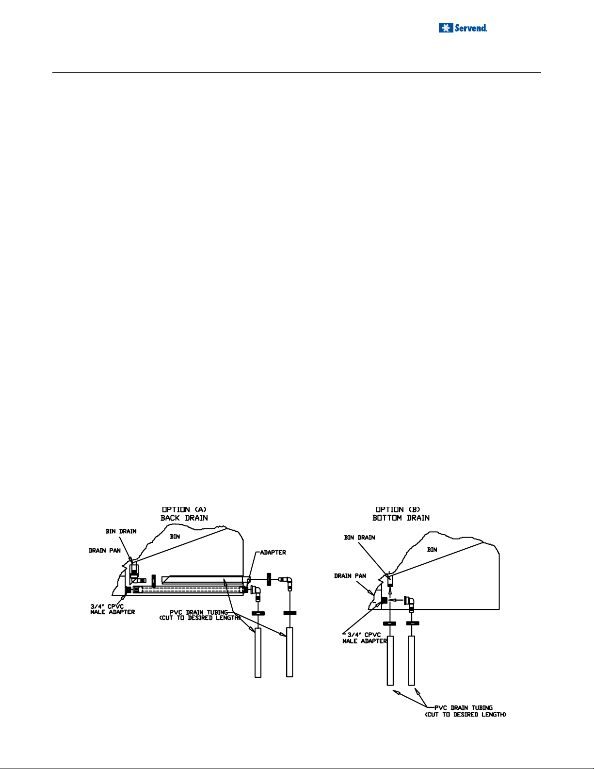
DRAINAGE OPTIONS
OPTION A
One drain tube fitting is with a 90° bend. This fitting attaches to the bin drain fitting. Underneath the dispenser
toward the front of the dispenser is the bin drain. Attach
the 90° fitting to the bin drain outlet. Slip the drain tubing
over the tubing end of the fitting. Secure the tubing with
the hose clamp provided.
The second drain tube fitting is a straight connector. This
fitting attached to the drain pan fitting of the dispenser.
Attach the fitting to the drain pan. Slip the drain tubing
over the tubing end of the fitting. Secure the tubing with
the hose clamp provided. Insulate all drain tubes.
OPTION B
One drain tube fitting is with a straight connector. This fitting attaches to the bin drain fitting. Underneath the dispenser toward the front of the dispenser is the bin drain.
Attach the straight fitting to the bin drain outlet. Slip the
drain tubing over the tubing end of the fitting. Secure the
tubing with the hose clamp provided.
The second drain tube fitting is a 90° bend. This fitting
attached to the drain pan fitting of the dispenser. Attach
the fitting to the drain pan. Slip the drain tubing over the
tubing end of the fitting. Secure the tubing with the hose
clamp provided. Insulate all drain tubes.
7
Page 8
Installation and Service Manual
OPERATION
UNIT INSPECTION
Thoroughly inspect the unit upon delivery . Immediately report any damage that occurred during transportation to the
delivery carrier. Request a written inspection report from a claims inspector to document any necessary claim.
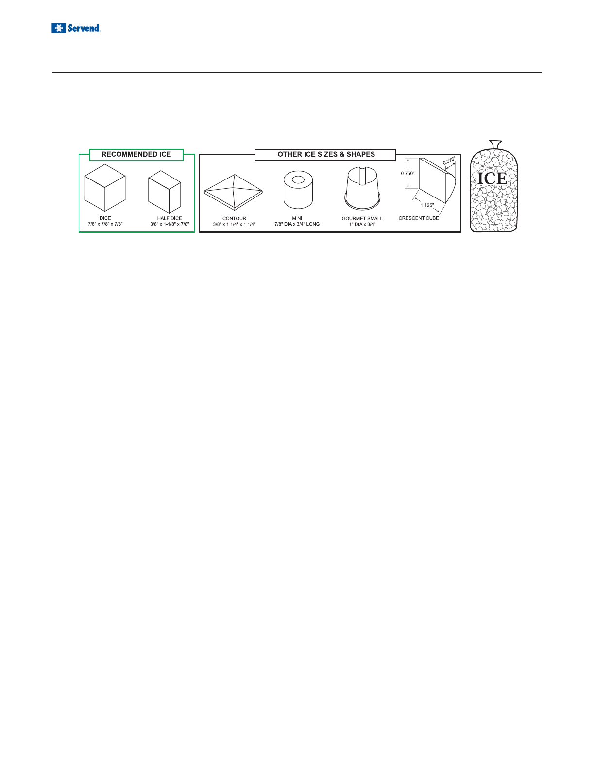
ICE RECOMENDED FOR DISPENSING
Servend dispensers are designed to dispense hard, cube ice up to one-inch square. The ice shapes and sizes
listed above are recommended for dispensing. Warm “Super Cooled” Ice Before Dispensing “Super Cooled”
ice is not recommended for dispensing. “Super cooled” ice is ice that has been stored in freezers below 32
Should it be necessary to temporarily use “super cooled” ice, allow the ice to warm at room temperature for 25
to 30 minutes before placing the ice in the dispenser.
ICE STORAGE AND DISPENSING
o
F.
Ice is stored in the dispenser’s bin. Ice is transported from the bottom of the bin to the ice dispense point by the paddle
wheel. The injection molded paddle wheel has paddles which lift the ice to the dispense point.
PUSH LEVER ICE DISPENSING
The customer’s cup presses against the push plate. The
push plate then raises a microswitch actuator arm on the
right side of the dispensing chute. The microswitch actuator arm hits the lever of the microswitch.
The energized microswitch activates the solenoid, which
pulls down the solenoid plunger. The plunger is connected
to a cable, which is then connected to a pulley . This raises
the door of the ice chute.
The energized microswitch also activates the gear motor.
The gear motor turns the agitator and paddle wheel, lifting
the ice from the bottom of the bin to the ice dispenser point.
Ice falls forward through the open door, through the bin
spout, through the ice chute and into the customer’s cup.
PUSH BUTTON ICE DISPENSING
Customer’s finger presses the push button, located in the
merchandiser frame. The button is labeled “ICE”
The push button energized the plunger microswitch. The
energized microswitch activating the solenoid, which pulls
down the solenoid plunger. The plunger is connected to a
cable, which is then connected to a pulley . This raises the
door on the ice chute.
The energized microswitch also activates the gear motor.
The gear motor turns the agitator and paddle wheel, lifting ice from the bottom of the bin to the ice dispense point.
The dispenser paddle wheel turns counter clockwise looking at the wheel from the outside front of the dispenser.
Ice falls forward through the open door, through the bin
spout, into the ice chute and into the customer’s cup.
BEVERAGE SYSTEM
Installation and maintenance of the beverage system is not covered in this manual. The Servend M series dispenser
is an ice only dispenser. In some applications, the dispenser provides a mounting location for optional beverage
valves. Please contact your MBE Service Company for installation and maintenance of your beverage system.
8
Page 9
OPERATION
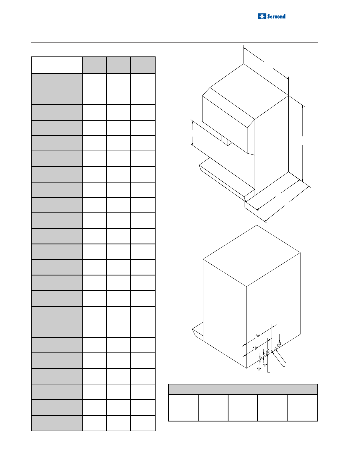
SPECIFICATIONS
Installation and Service Manual
M-15 M-45 M-90
Width 38.1 cm
(15")
Depth - overall 71.1 cm
Depth - cou nter
top
Height 81.3 cm
Dispense Heig ht 24.8 cm
Bin Top S ize -
width
Bin Top S ize depth
Rear "A" 19.1 cm
Rear "B" 19.1 cm
Hole "E" Height
(to p h o le)
(28")
66 cm
(26")
(32")
(9 .75" )
38.1 cm
(15")
52.1 cm
(20.5")
(7 .5")
20.5 cm
(8 .06" )
38.1 cm
(15")
71.1 cm
(28")
66 cm
(26")
61.6 cm
(32")
24.8 cm
(9.7 5" )
38.1 cm
(15")
45.4 cm
(17.88")
29.3 cm
(11.5 ")
(7.5 ")
38.1 cm
(15")
71.1 cm
(28")
66 cm
(26")
81.3 cm
(32")
24.8 cm
(9.75")
38.1 cm
(15")
45.7 cm
(18")
29.2 cm
(11.5")
19.1 cm
(7.5")
WIDTH
DISPENSE HEIGHT
HEIGHT
DEPTH COUNTERTOP
DEPTH OVERALL
Hole "F"
Diameter
Hole "G"
Diameter
Hole "H" H eight
(b o tto m h o le )
Hole "E"
Diameter
Hole "H"
Diameter
Right side to bin
drain
Right side to
drain pan drain
Rear to bin drain 35.9 cm
Rear to drain pan
drain
Bin drain fitting
size
Drain pan fitting
size
Ice storage
capacity
Motor
Horsepower
7.8 cm
(3 .06" )
5 cm
(2")
5 cm
(2")
19.0 cm
(7 .5")
25.4 cm
(10.0")
(14.12")
53.3 cm
(21.0")
3/4"
M.I.P.T.
3/4"
M.I.P.T.
40.8 kg
(90lb)
1/15 1/15 1/15
5 cm
(2" )
5 cm
(2" )
18.8 cm
(7.5 ")
25 cm
(10")
38.7 cm
(15.25")
47.6 cm
(18.75")
3/4"
M.I.P.T.
3/4"
M.I.P.T.
20.4 kg
(45lb)
5 cm
(2")
5 cm
(2")
16.8 cm
(6.62")
25.4 cm
(10.0")
35.9 cm
(14.12")
53.3 cm
(21.0")
3/4"
M.I.P.T.
3/4"
M.I.P.T.
40.8 kg
(90lb)
120 Volts 60 Hz. - 1.2
amp (U.S.
Standard)
HOLE "H"
HOLE "E"
Electric voltage - Cycle - Amperage
100 Volts 50 / 60 Hz.
- N/A
220 Volts 50 Hz. -
0.44 amp
220 Volts
60 Hz. - N/A
HOLE "G"
HOLE "F"
240 Volts
50 Hz. -
0.35 amp
9
Page 10
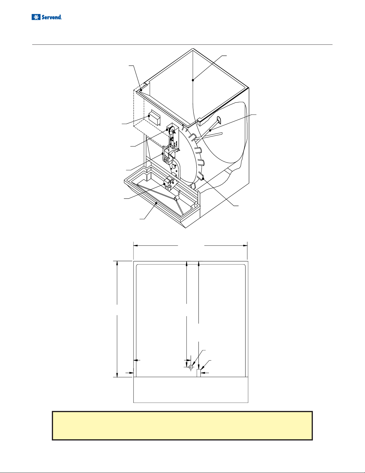
Installation and Service Manual
ELECTRICAL BOX
OPERATION
ICE BIN
MANUAL FILL AREA
(M-200 & LARGER)
AGITATOR
DOOR ASSEMBLY
ICE CHUTE
GEAR MOTOR
DRAIN PAN
BIN LEGNTH
RIGHT
SIDE
REAR TO
BIN DRAIN
RIGHT SIDE TO BIN DRAIN
BIN WIDTH
REAR
REAR TO
DRAIN PAN
DRAIN
PADDLE WHEEL
LEFT
SIDE
BIN DRAIN
DRAIN PAN DRAIN
10
RIGHT SIDE TO DRAIN P AN DRAIN
DRAIN PAN
CAUTION: Cutting the countertop may decrease its strength. Counter should
be braced to support the dispenser countertop weight plus ice storage capacity and weight of icemaker, if applicable.
Page 11

OPERATION
AGITATION TIMER
The agitation timer is standard equipment for the dispensers with
90.7 kg. (200 lbs.) and larger bin storage. This timer is available
as an option for all other dispensers. The purpose of the timer is
to periodically agitate the ice in the bin, preventing the ice from
congealing together.
The timer is located in the electrical box of the dispenser. The two
dials on the timer should be set to agitate the ice for two seconds
every four hours of non ice dispenser use.
T o check the agitation timer , turn the off time dial (right dial on the
drawing below) counter clockwise until the dial stops. Do not use
the dispenser for 15 minutes. Within that time period, the agitator
will turn. If the agitator does not turn, replace the timer .
If the solenoid is electrically activated when the agitation timer
moves the gear motor, the timer has shorted out internally and
must be replaced.
T o correctly reset the agitation timer, turn both dials counter clockwise until they stop. Y our “point s” on the dials will be set at “0”.
Turn the ON time (left dial) from the “0” to the “2”.
Turn the OFF time (right dial) from the “0” to the “4”.
The drawing shows the position of the dials when the timer is set
correctly .
Installation and Service Manual
DOOR
The door is used to stop the flow of ice to the container when the microswitch is released. The door assembly is not
used to reduce the flow of ice. See the ice flow reducer section.
When operated, the door should open completely. This
would be a minimum of 3.8 cm (1.5 in) as measured
from the bottom of the chute opening to the bottom
of the door when energized.
To adjust the door opening, raise or lower the door solenoid in the opposite direction you wish to effect the door .
EXAMPLE: If you wish to open the door wider, lower the
door solenoid. This will raise the door wider.
To move the solenoid, loosen the four machine screws
on the side of the coil. Slide the solenoid in the direction
you wish to move it. Tighten the screws on the solenoid
to secure the coil in place.
11
Page 12

Installation and Service Manual
OPERATION
GEAR MOTOR REMOVAL
These instructions are provided as a guide for the removal of the gear motor. Depending on the model number of your
dispenser, these instructions may vary slightly.
1. Disconnect power from the electric receptacle.
2. Remove all ice from the ice storage bin of the dispenser.
3. Remove the paddle wheel pin from the paddle wheel
/ agitator assembly inside the dispenser bin.
4. Remove the agitator assembly from the dispenser
bin by pushing the agitator to the back of the bin.
Angle the front of the agitator to the side. Pull the
agitator forward then out of the dispenser.
5. Remove the paddle wheel from the dispenser by
pulling the hub of the paddle wheel to the back of
the bin and off the gear motor shaft.
6. Remove the four bolts from the front wall of the dispenser. These bolts mount into the gear motor case.
7. Remove the front from the dispenser and expose
the gear motor.
8. Disconnect the electric connector from the gear motor wire leads.
9. Remove the strap from around the gear motor.
10. You should be able to remove the gear motor from
the dispenser.
11. To install a replacement gear motor, reverse this
procedure.
ICE BIN
GEAR MOTOR
BIN FLOW RESTRICTOR & ICE FLOW
The delivery of the ice from the dispenser is influenced by
several factors. The primary influence is the type of ice being
dispensed. If you are dispensing a wet, rounded corner ice,
this ice will dispense at a faster rate than an ice with square
corners.
Regardless of the ice you are dispensing, it is possible to
reduce the delivery of the ice. However the reduction will
AGITATOR
PADDLE WHEEL
depend upon the type of ice. DO NOT REDUCE THE DOOR
OPENING TO REDUCE ICE FLOW .
A flow restrictor is available as an option for installation in the
dispensing chute of the dispenser. This restrictor will prevent
a full paddle wheel “cup” of ice from being delivered into the
chute. This will then reduce the delivery of ice to the container.
12
Page 13

OPERATION
BIN FLOW RESTRICTOR & ICE FLOW
To install the ice flow restrictor:
1. Remove the merchandiser.
2. Remove the door assembly.
3. Drill 3/16” hole in top of chute from the bin as shown
in the above drawing.
Installation and Service Manual
4. Place the restrictor in the chute, holding with the bolt
and nut.
5. Tighten nut.
6. Replace door assembly and merchandiser.
USER MAINTENANCE
CLEANING AND SANITIZING
CAUTION: All cleaning must meet your local health department regulations. Use only warm
soapy water to clean the exterior of the tower. Do not use solvent s or other cleaning agents. Do not
pour hot coffee into the drain pan. Pouring hot coffee down the drain pan can eventually crack the
drain pan, especially if the drain pan is cold or still contains ice.
1. Unplug the dispenser from the electric receptacle.
2. Mix a cleaning solution consisting of a mild non abrasive detergent with water according to the package
directions.
3. Using the cleaning solution and a soft bristle brush or
cloth, wash the following dispenser parts: (With a top
mounted ice maker, accessibility is through the front
opening of the ice maker.) Paddle wheel pin (removed
from the dispenser) Agitator (removed from the dispenser) Paddle wheel (removed from the dispenser)
Entire bin area Ice chute Rear agitator bushing Drive
shaft assembly inside bin.
4. Mix a solution of 1.5 cl (1/2 oz.) household bleach to
7.5 L (2 gal) of clean water. To achieve 5.25% Cl Na
O concentration per gallon of water, the mixture should
supply 100 PPM (parts per million) of available
chlorine. Or mix a solution of any NSF approved sanitizer, following the directions for mixing and applying
that sanitizer.
5. Using the sanitizing solution and a soft bristle brush
or cloth, clean each of the dispenser parts listed above.
6. Do not rinse the parts af ter they have been sanitized.
Replace all parts back to the dispenser.
7. Pour in fresh clean ice into the dispenser bin. Or turn
the ice maker back on.
8. Plug the dispenser into the receptacle.
9. Check for proper ice dispensing.
13
Page 14

Installation and Service Manual
EXPLODED VIEWS, PARTS & DIAGRAMS
M-15A/15B/45/90 STANDARD ALL VOLTAGES
TO ELECTRIC
POWER SUPPLY
TO ELECTRIC
POWER
SUPPLY
M-15C STANDARD ALL VOLTAGES
14
Page 15

Installation and Service Manual
EXPLODED VIEWS, PARTS & DIAGRAMS
M-15C WITH AGITATION TIMER
M-90 WITH LIGHTS AND VALVES ALL VOLTAGES
15
Page 16

Installation and Service Manual
KEY # DESCRIPTION PART NUMBER (all models)
1 Lid 4100075
2 Flipper Door 4105503
3 Flipper Door Rod 4100008
4 Flipper Door Frame 4105502
5 Paddlewheel 2602235
6 Agitator 4105706
7 Paddlewheel Pin 5001683
8 Drain Kit Assembly 2602528
9 Mushroom Bushing O101702
11 Bin Insulator Plate 7015901
51 1/4-20 x 1" Stainless Steel Hex Head Cap Screw O900636
52 8 x 3/4 Stainless Steel Tapping Screw O901007
EXPLODED VIEWS, PARTS & DIAGRAMS
M-15 EXPLODED VIEW (TOP)
16
Page 17

Installation and Service Manual
EXPLODED VIEWS, PARTS & DIAGRAMS
M-15 EXPLODED VIEW (BASE)
KEY # DESCRIPTION PART NUMBER (all models)
10 Bin Insulator 2601968
Gearmotor 115 Volt - 60 Hz 1000120
100 Volt - 50/60 Hz 1000120
12
220 Volt - 50 Hz 5000345
220 Volt - 60 Hz 5000345
240 Volt - 50 Hz 5000345
13 Motor Cover 4100024
14 Vinyl Grommet O905702
15 Motor Brace 4570042
16 Large Radiator Clamp O903205
Capacitor for Gearmotor (5 mfd)115 Volt - 60 Hz 1001741
(8 mfd)100 Volt - 50/60 Hz 1001710
17
(3 mfd)220 Volt - 50 Hz 5000344
(3 mfd)220 Volt - 60 Hz 5000344
(2 mfd)240 Volt - 50 Hz 5000343
18 Capacitor Bracket 4100062
19 Electrical Box Assembly 4100051
20 Shield for Transformer & Relay 5002242
21 24 Volt Relay 5000900
KEY # DESCRIPTION PART NUMBER (all models)
Transformer 115 Volt - 60 Hz 1001424
100 Volt - 50/60 Hz 5001087
22
220 Volt - 50 Hz 5000967
220 Volt - 60 Hz 5000967
240 Volt - 50 Hz 5000967
30 Power Cord 115 Volt - 60 Hz ONLY 2600711
39 Electric Box Lid 1000507
40 Bin Insulator Gasket O400231
41 Motor Shaft Sleeve 2602236
42 1/4 x 5/8 Spring Pin O905005
43 Wiring Diagram 5002215
44 Motor Insulator Spacer 2602208
46 Galvanized Extension - Left 4100070
47 Galvanized Extension - Right 4100071
48 Finger Guard 4100063
49 Mylar Foam Hole Cover O301203
50 8 x 1/2 Stainless Steel Tapping Screw O901001
54 10-32 x 1/2" Screw O901301
55 10-32 ESNA Nut O902316
56 Ground Screw O903903
57 1/4-20 x 3/8 Bolt O900635
17
Page 18

Installation and Service Manual
EXPLODED VIEWS, PARTS & DIAGRAMS
M-15 A EXPLODED VIEW (FRONT)
18
KEY # DESCRIPTION PART NUMBER
21 Inner Ice Shield 4100038
22 Push Plate Retaining Bracket 4100007
Door Assembly (LESS SOLENOID COIL) - see page 36 for
23
solenoid door parts
24 Drip Pan Assembly 4105901
25 Drip Pan Rod 4100000
26 Hitch Pin O905209
27 UL Cover 4100022
28 2 1/8" Heyco Plug 1200320
29 UL Cover Top Angle (2 required) 4100069
31 Fake Valve Cover 4105508
32 Vented Heyco Plug 1200321
33 Pushplate 4100054
34 "ICE" Sticker O301299
46 10-32 x 1/2 Thumb Screw O901501
47 8 x 1/2 Stainless Steel Tapping Screw O901001
56 Fake Valve Alignment Brace 4100006
4105908
Page 19

Installation and Service Manual
EXPLODED VIEWS, PARTS & DIAGRAMS
M-15 B EXPLODED VIEW (FRONT)
KEY # DESCRIPTION PART NUMBER
21 Inner Ice Shield 4100038
Door Assembly (LESS SOLENOID COIL) - see page 36 for
23
solenoid door parts
24 Drip Pan Assembly 4105901
25 Drip Pan Rod 4100000
26 Hitch Pin O905209
27 UL Cover 4100022
28 2 1/8" Heyco Plug 1200320
29 UL Cover Top Angle (2 required) 4100069
31 Fake Valve Cover 4105508
32 Vented Heyco Plug 1200321
33 Push Button 5006080
34 "ICE" Sticker O301299
47 8 x 1/2 Stainless Steel Tapping Screw O901001
55 Fake Valve Alignment Brace 4100006
4105908
19
Page 20

Installation and Service Manual
EXPLODED VIEWS, PARTS & DIAGRAMS
M-15 C EXPLODED VIEW (FRONT)
KEY # DESCRIPTION PART NUMBER
Door Assembly (LESS SOLENOID COIL) - see page 36 for
23
solenoid door parts
24 Drip Pan Assembly 4105901
25 Drip Pan Rod 4100000
26 Hitch Pin O905209
27 UL Cover 4100022
28 2 1/8" Heyco Plug 1200320
29 UL Cover Top Angle (2 required) 4100069
31 False Valve Cover 5002229
32 Solenoid Cover 4100076
33 Vented Heyco Plug 1200321
34 Cover Chute 4100072
35 Push Button 5002217
36 "ICE" Sticker O301299
37 "DO NOT LIFT BY SHROUD" Sticker 5002473
38 "ICE" Sticker (Push Button) 5002538
45 6-32 x 3/8 Screw 5002197
50 8 x 1/2 Stainless Steel Tapping Screw O901001
53 8-32 x 1/2 Knurl Screw O904403
58 Fake Valve Alignment Brace 4100006
--- Timed Agitation Kit 5006794
--- Flow Restrictor Kit 5006796
--- Compressed Ice Agitator Kit 5006903
5002533
20
Page 21

Installation and Service Manual
EXPLODED VIEWS, PARTS & DIAGRAMS
M-45/90 EXPLODED VIEW (BASE)
See Electrical
view
21
Page 22

Installation and Service Manual
EXPLODED VIEWS, PARTS & DIAGRAMS
M-45/90 EXPLODED VIEW (BASE)
KEY # DESCRIPTION
1 Agitator 7015702 7015702
2 Paddlewheel Pin 5001683 5001683
3 Paddlewheel 2602235 2602235
4 Mushroom Bushing O101702 O101702
5 Lid 4570035 4570035
6 Bin Insulator 2601968 2601968
19 Screw for Mushroom Bushing O901001 O901001
20 Motor Cover 4630035 4570043
Gearmotor 115 Volt 60 Hz 1000120 1000120
100 Volt 50/60 Hz 1000120 1000120
220 Volt 60 Hz 5000345 5000345
21
240 Volt 60 Hz 5000345 5000345
220 Volt 50 Hz 5000345 5000345
240 Volt 50 Hz 5000345 5000345
PART NUMBER
M 45
PART NUMBER
M 90
22 Bin Insulator Plate 7015901 7015901
23 Bin Insulator Gasket O400231 O400231
24 Cosmetic Motor Cover 7010127 7010127
25 Stand Off Wire Tie 1000430 1000430
26 Wiring Diagram 5000016 5000016
Door Assembly (LESS SOLENOID COIL) - see
27
page 36 for solenoid door parts
28 Motor Brace 4570042 4570042
29 Splash Panel Clip 7000002 7000002
30 Extra Large Radiator Clamp O903205 O903205
42 Electric Cord 2600711 2600711
44 Drain Kit 2602528 2602528
45 Motor Insulator Spacer 2602208 2602208
47 Motor Shaft Sleeve Roll Pin O905005 O905005
48 Motor Shaft Sleeve 2602236 2602236
4635907 4575918
22
Page 23

Installation and Service Manual
EXPLODED VIEWS, PARTS & DIAGRAMS
M-45/90 EXPLODED VIEW (FRONT)
KEY # DESCRIPTION
Medallion - PL ICE 5000167 O300102
- PL with valves ICE N / A 5006865
- PB ICE N / A 5006866
7
- PB with valves ICE N / A 5006867
- PL PEPSI N / A O300170
- PB with valves WHITE N / A 5006730
- PB with valves CLEAR N / A 4572101
8 Merchandiser (includes angles) 4635902 4575803
9 Splash Panel 4570024 4570024
10 Push Plate 7060000 7060000
11 Chute Mounting Bracket 7010003 7010003
12 Push Plate Brace 7010032 7010032
13 Ice Chute 4575506 4575506
14 Fluorescent Tube 1000318 1000318
15 Drain Pan Pin 7010008 7010008
16 Drain Pan 4575914 4575914
17 Drain Pan Grid O100119 O100119
18 Microswitch Actuator Slide 7060002 7060002
Door Assembly (LESS SOLENOID COIL) - see
27
page 36 for solenoid door parts
Ballast 120 Volts 60 Hz 1000315 1000315
100 Volts 50/60 Hz 5000870 5000870
31
220 Volts 50 Hz 5000348 5000348
220 Volts 60 Hz 5000349 5000349
240 Volts 50 Hz 5000350 5000350
32 Light Socket Bracket 7050046 7050046
33 Fluorescent Light Socket 1001001 1001001
34 Microswitch Actuator 4630031 7010017
PART NUMBER
M 45
4635907 4575918
PART NUMBER
M 90
23
Page 24

Installation and Service Manual
EXPLODED VIEWS, PARTS & DIAGRAMS
M-45/90 EXPLODED VIEW (FRONT)
KEY # DESCRIPTION
35 Starter Base 1001006 1001006
36 Fluorescent Starter 1001005 1001005
37 Shoulder Plate 7060016 7060016
38 Electrical Box Cover 1000507 1000507
39 Electric Box 4635906 4575912
Capacitor 120 Volts 60 Hz 1001741 1001741
100 Volts 50/60 Hz 1001710 1001710
40
220 Volts 50 Hz 5000344 5000344
220 Volts 60 Hz 5000344 5000344
240 Volts 50 Hz 5000343 5000343
41 Capacitor Bracket 1001707 1001707
43 Merchandiser UL Angle (Right) 4630025 4570052
46 Merchandiser UL Angle (Left) 4630027 4570064
PART NUMBER
M 45
PART NUMBER
M 90
M-45/90 EXPLODED VIEW (FRONT NOT SHOWN)
KEY # DESCRIPTION
--- Motor Plate Bolts O900636 O900636
Leg 4" Plastic 5000684 5000684
---
Empty light 115 Volt 60 Hz 5006233 5006233
---
Buzzer Alarm 115 Volt 60 Hz 1001501 1001501
---
--- Heavy Duty Lid N / A 5000829
--- Ice Flow Restrictor 7012003 7012003
--- Light Kit 5001579 4572121
--- Push Button Switch Assembly 1001120 1001120
Transformer for Valves 115 Volt 60 Hz 1001424 1001424
---
Extended Splash Panel Standard N / A 4572134
---
--- Grid Lifter 7012155 4572039
--- Nugget Adaptor Kit 5001207 5001207
4" Stainless 5001021 5001021
2 1/2" black 5000920 5000920
220 / 240 Volt 50 / 60 Hz 5000391 5000391
220 / 240 Volt 50 / 60 Hz 5000390 5000390
100 Volt 50/60 Hz 5001087 5001087
220 Volt 50 Hz 5000967 5000967
220 Volt 60 Hz 5000967 5000967
240 Volt 50 Hz 5000967 5000967
Punched for 4 Flomatic Valves N / A 5000403
PART NUMBER
M 45
PART NUMBER
M 90
24
Page 25

Installation and Service Manual
EXPLODED VIEWS, PARTS & DIAGRAMS
M-90 EXPLODED VIEW (FRONT)
25
Page 26

Installation and Service Manual
EXPLODED VIEWS, PARTS & DIAGRAMS
KEY # DESCRIPTION PART NUMBER
8 Left Merchandiser Angle 4590057
9 Right Merchandiser Angle 4590054
10 Ice Chute 5001991
11 Knurled Screw O904403
12 Splash Panel Punched for 4 Valves 5000403
23 Translight - All You Can Drink 5000635
24 Merchandiser 5001477
31 Clear Medallion 5000611
32 Opaque Medallion 5000406
33 Push For Ice Switch - 2" Square 1001120
34 Medallion Screw O904403
36 Splash Panel Screw 0901001
M-90 EXPLODED VIEW (FRONT)
26
Page 27

Installation and Service Manual
TROUBLESHOOTING
CONDITION INVESTIGATION HOW TO CHECK CORRECTION
Dispenser does not dispense
ice.
Dispenser does not dispense
ice.
There is no power to the
dispenser.
There is power to the
dispenser, however nothing
runs.
The gear motor runs but the
dispensing paddle wheel
doe s not turn.
Gear mo to r runs but the
dispensing paddle wheel
doe s not turn.
Is the dispenser plugged in? Plug the dispenser in.
The dispenser is plugged in
with power to the receptacle.
With a me ter, check to see i f
power is getting to the white
and black cord wires inside
the electric box.
Is power goi ng through the
microswitc h? W ith the
dispenser plugged i n, meter
probes on the “C” and “NC ”
terminals of the mi croswitch,
energize the microswitch. If
the meter starts out
registering voltage, then does
not register voltage when the
switch is pushed, the switch
is good.
If the g ear mo to r a tte mpts to
start but fails to do so, check
the capacitor. To completely
check the ca pa citor, you must
use a capacitor checker
according to the instructions
supplied.
If gear moto r fa ils to attempt
to start, check the gear motor.
To check the gear motor,
disconnect power from the
dispenser. Disconnect the
gear motor wires in the
junction box. Check for
continui ty through the gear
motor.
Remove the paddle wheel pin
in the bin area. Is this pin
broken or missing?
Remove the agitator and
paddle wheel. Are you able
to turn the shaft from the gear
motor wi thout turning the
motor a rmature itse lf?
If no power is present, check
the cord and plug of the
dispenser. Replace if broken
wire or connection is
detected.
If no power is going through
the microswitch, replace the
switch or locate the broken
connection.
If capacitor does not test
correctly, replace the
capacitor.
If gear motor does not test
correctly, replace the gear
motor.
If the paddle wheel pin is
broken or missing, replace
the pin.
Lower i ce bin level.
Dispenser crushes ice as it
dispenses.
Dispenser runs but does not
dispense ice.
Is the ice in the bin of the
proper size and type of ice?
Is there at least one half bin
of ice?
Is the ice in the bin of the
proper size and type of ice?
Is the bin drain clean and
open?
See page 5 for acceptable
ice.
Is the ice being used a full
size pi ece of ice? i.e. cubes
full, not shallow, etc.
Adjust door to minimum or
larger opening.
Microswitch may be sticking.
Check the microswitch and
linkage to the microswitch.
Clean linkage and
micros witch. Re p lace
microswitch if necessary.
27
Page 28

Installation and Service Manual
28
Page 29

Installation and Service Manual
29
Page 30

Installation and Service Manual
30
Page 31

INDEX
B
brixing ....................................... 2
C
Carbon Dioxide ......................... 5
CAUTION .......................... 11, 12
claims ........................................ 8
Cleaning .................................... 2
CO 2........................................... 4
CO2 monitors ............................ 4
cube ice .................................... 8
D
damage ................................ 2, 8
delivery ................................ 2, 8
Diagrams
14, 15, 16, 17, 18, 19, 20, 21, 22, 23, 24, 25, 26
Dispensing ................................ 8
distributor.................................. 2
F
FOREWORD .............................. 2
H
health department................... 12
I
Ice ............................................. 8
Ice Storage................................ 8
INSPECTION .............................. 2
inspection ............................ 7, 8
Installation Date ........................ 2
irregularities .............................. 2
M
Maintenance ........................... 13
MBE ........................................... 2
Model Number ........................... 2
modifications............................. 5
O
Operation .................................. 5
Q
Qualified Service Personnel..... 5
R
regulations .............................. 12
Relocation ................................. 5
return procedures .................... 2
S
SAFETY ............................... 5, 6
sanitizing................................... 4
Serial Number ........................... 2
service assistance ................... 2
Service Personnel .................... 5
Shipping .................................... 5
Shipping, Storage, Relocation .. 5
soa py wate r ........................... 12
solvents .................................. 12
start-up ..................................... 5
Storage ..................................... 5
T
TROUBLESHOOTING .............. 27
U
Unit Inspection .......................... 8
UNPACKING .............................. 2
W
Warning .................................... 5
WARRANTY INFORMA TION ..... 2
water-to-syrup ratio. See brixing
Page 32

Manitowoc Beverage Equipment
2100 Future Drive Sellersburg, IN 47172-1868
Tel: 812.246.7000, 800.367.4233 Fax: 812.246.9922
www.manitowocbeverage.com
In accordance with our policy of continuous product development and
improvement, this information is subject to change at any time without notice.
5011634 March 23, 2005 REV1
 Loading...