

Page 1
Manitowoc
BG0260
Spray Cube
Technician’s
Handbook
This manual is updated as new information and models are released.
Visit our website for the latest manual. www.manitowocfsg.com
America’s #1 Selling Ice Machine
Part Number STH48 6/15
Page 2

Page 3

General Information
Model Numbers ...................................5
BG0260A .............................................5
Model/Serial Number ...........................5
Manitowoc Cleaner and Sanitizer ........ 5
Installation
Location of Ice Machine ......................7
Installation Requirements ....................7
Potable Water Requirements .............. 8
Drain Connections ...............................8
Ice Machine Clearance Requirements 8
Electrical Service .................................9
Operation
Ice Making Sequence of Operation .........11
Thermostat settings .............................13
Maintenance
Cleaning & Sanitizing Procedure ......... 16
Cleaning the Condenser .....................20
Removal from Service/Winterization ...21
Page 4

Troubleshooting
Electrical Flowcharts ................................23
Electrical Flowchart Ice Machine Will Not
Run ...................................................... 24
Will Not cycle Into Harvest ...................28
Prematurely Cycles Into Harvest .........31
Refrigeration Troubleshooting ................34
Ice Production/Quality Check ..............35
Component Specifications
Thermostat Settings ............................41
Fan Cycle Control Settings ..................41
Total System Refrigerant Charge ........41
Filter-Driers .......................................... 42
Suction Cleanup Filter-Drier ................42
Charts
Cycle Times/24-Hour Ice Production/
Refrigerant Pressure Charts ....................43
BG0260A .............................................44
Diagrams
Wiring Diagram .........................................45
BG0260 ...............................................46
Refrigeration Tubing Schematics ...........47
Page 5
General Information
MODEL NUMBERS
BG0260A
MODEL/SERIAL NUMBER
These numbers are required when requesting
information from your local Manitowoc Distributor, or
Manitowoc Ice. The model and serial number are
listed on the MODEL/SERIAL NUMBER DECAL
affixed to the ice machine.
MANITOWOC CLEANER AND SANITIZER
Manitowoc Ice Machine Cleaner and Sanitizer are
available in 16 oz. (473 ml) bottles. These are the only
cleaners and sanitizer approved for use with
Manitowoc products.
Cleaner Part Number Sanitizer Part Number
16 oz. 000000084 16 oz. 9405653
1 gal N/A 1 gal. 9405813
Part Number STH48 6/15 5
Page 6

6 Part Number STH48 6/15
This Page Intentionally Left Blan k
Page 7

Installation
LOCATION OF ICE MACHINE
The location selected for the ice machine must meet
the following criteria. If any of these criteria are not
met, select another location.
• The location must be free of airborne and other
contaminants.
• The location must not be near heat-generating
equipment or in direct sunlight.
• The location must be capable of supporting the
weight of the ice machine and a full bin of ice.
• The location must allow enough clearance for
water, drain and electrical connections in the rear
of the ice machine.
• The location must not obstruct airflow through or
around the ice machine.
INSTALLATION REQUIREMENTS
• The air temperature must be at least 50°F (10°C),
but must not exceed 110°F (43°C).
• The water temperature must be at least 50°F
(10°C), but must not exceed 100°F (38°C).
• The ice machine and bin must be level
• Vent the ice machine and bin drains separately
• Bin drain termination must have an air gap
• A back flow preventer is required on water inlet
lines
• Routine adjustments and maintenance procedures
outlined in this manual are not covered by the
warranty.
Part Number STH48 6/15 7
Page 8

POTABLE WATER REQUIREMENTS
• Plumbing must conform to local codes
• Do not connect the ice machine to a hot water
supply. Be sure all hot water restrictors installed for
other equipment are working. (Check valves on
sink faucets, dishwashers, etc.)
• If water pressure exceeds maximum pressure (6
bar) obtain a water pressure regulator from your
Manitowoc distributor.
• A union for both the ice making and condenser
water lines is required
• Water inlet lines require insulation to prevent
condensation.
DRAIN CONNECTIONS
• Drain lines must have a 1.5 inch drop per 5 feet of
run (2.5 cm per meter), and must not create traps
• The floor drain must be large enough to
accommodate drainage from all drains.
• Separate insulated bin and water-cooled
condenser drain lines are required
• The bin and ice machine drains require a vent.
ICE MACHINE CLEARANCE REQUIREMENTS
Air-Cooled Water-Cooled
Top/Sides 5" (13 cm) 5" (13 cm)
Back 8" (20 cm) 8" (20 cm)
8 Part Number STH48 6/15
Page 9

ELECTRICAL SERVICE
!
Warning
!
Warning
All wiring must conform to local and national codes.
Voltage
The maximum allowable voltage variation is ± 10% of
the rated voltage on the ice machine model/serial
number plate at compressor start-up.
Fuse/Circuit Breaker
A separate fuse/circuit breaker must be provided for
each ice machine.
The ice machine must be grounded in accordance
with national and local electrical codes.
Ground Fault Interrupter Circuit (GFIC)
A GFCI/GFI circuit protection is not recommended
with our equipment. If a GFCI/GFI is required by code
a GFCI/GFI breaker rather than outlet must be used to
avoid intermittent nuisance trips.
Part Number STH48 6/15 9
Page 10

10 Part Number STH48 6/15
This Page Intentionally Left Blan k
Page 11

Operation
Ice Making Sequence of Operation
Priming the Water system
The water inlet valve on this machine energizes in the
harvest sequence, therefore priming the system with
water will allow the system to start up with a full
reservoir of water. To prime system add 2 liters of
water into the water trough.
1. Freeze Cycle
Turn the toggle switch to ON. The compressor, and
water pump will energize, starting the freeze cycle.
The pump sprays water into the inverted cups. The
water freezes layer by layer, until an ice cube forms in
each cup.
The freeze cycle continues and the evaporator
thermostat reaches the adjusted se t po i nt .
The thermostat energizes the timer motor and the cam
starts to turn. When the cam cycles through the preset
freeze time the relays change position and the harvest
cycle starts.
Part Number STH48 6/15 11
Page 12

2. Harvest Cycle
The compressor continues to operate and the water
pump is de-energized. The harvest valve energizes,
allowing hot gas to enter and warm the evaporator.
The water valve is also energized, aiding with harvest,
as well as filling up the sump with fresh water for a
new freeze cycle.
The ice falls from the cups and drops into the bin. The
harvest cycle continues until the preset harvest time
expires.
The harvest valve and water valve de-energize. If ice
cubes are not contacting the bin thermostat, a new
freeze cycle is initiated and the water pump energizes
and sprays water into the cups.
3. Automatic Shut-Off
When the storage bin is full, ice will contact the bin
thermostat inside the bin. If the bin thermostat opens
during a freeze cycle the ice machine will finish the
freeze cycle and stop when it enters the harvest cycle.
The ice machine remains off until enough ice has been
removed from the storage bin to allow the ice to fall
clear of the bin thermostat probe. As the ice clears the
probe, the bin thermostat warms up and the machine
starts another freeze cycle.
12 Part Number STH48 6/15
Page 13
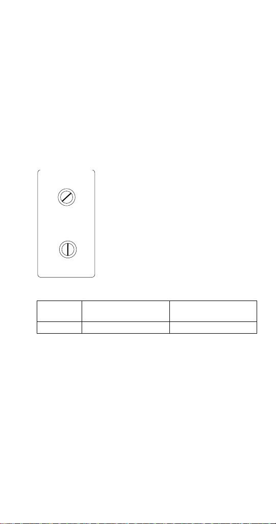
THERMOSTAT SETTINGS
1
2
3
4
5
6
7
1
2
3
4
5
6
7
Bin Thermostat
Small Numbers = Less ice in bin
Large Numbers = More ice in bin
Start at Chart Setting, then adjust as
required
Evaporator Thermostat
Small Numbers = Large dimple & lighter
cubes
Large Numbers = Small Dimple & heavier
cubes
Refer to chart for initial setting
Bin Thermostat:
The bin thermostat sensing bulb is located in holder on
the right side of the bin on self storage models. The
bin thermostat turns the ice machine on and off as the
level of ice in the bin changes. Use the initial setting
from the chart and adjust as required.
Evaporator Thermostat:
The evaporator thermostat energizes the timer motor.
After the preset time on the timer expires the harvest
cycle begins. Refer to chart for correct setting.
Thermostat Setting Chart
Model
Bin Thermostat
Setting
Evaporator
Thermostat Setting
BG0260 5 4
Part Number STH48 6/15 13
Page 14

14 Part Number STH48 6/15
This Page Intentionally Left Blan k
Page 15
Maintenance
!
Caution
!
Warning
Clean and sanitize the ice machine every six months
for efficient operation. If the ice machine requires more
frequent cleaning and sanitizing, consult a qualified
service company to test the water quality and
recommend appropriate water treatment.
An extremely dirty ice machine must be taken apart for
cleaning and sanitizing.
Use only approved Ice Machine Cleaner and
Sanitizer. Read and understand all labels printed on
bottles before use. Do not mix Ice Machine Cleaner
and Sanitizer solutions together.
Wear rubber gloves and safety goggles (and/or face
shield) when handling Ice Machine Cleaner or
Sanitizer
Part Number STH48 6/15 15
Page 16

CLEANING & SANITIZING PROCEDURE
!
Caution
Ice machine cleaner is used to remove lime scale or
other mineral deposits. Sanitizer is used to remove
algae or slime.
Mix 4 liters of water with 500 ml of cleaner in a plastic
or stainless container.
Cleaner Water
16 oz (500 ml) 1 gal (4L)
Step 1 Open the front door to access the evaporator
compartment. Ice must not be on the evaporator
during cleaning and sanitizing. Follow one of the
methods below:
• Press the power switch at the end of a
harvest cycle after ice falls from the
evaporator(s).
• Press the power switch and allow the ice to
melt.
Never use anything to force ice from the
evaporator. Damage may result.
Step 2 Remove all ice from the bin and remove top
cover of ice machine
Step 3 Remove overflow tube and drain water sump.
Step 4 Remove all parts for cleaning.
A. Remove two thumbscrews and shutter
assembly
B. Remove ice cube slide
C. Remove spray bar and vinyl tubing
D. Evaporator shield on top of evaporator
NOTE: The tubing, spray bar ends and nozzles can be
removed when required for easier cleaning.
.
Mix a solution of cleaner and lukewarm water.
16 Part Number STH48 6/15
Page 17

Step 5 Depending upon the amount of mineral
buildup, a larger quantity of solution may be required.
Use the ratio in the table below to mix enough solution
to thoroughly clean all parts.
Solution Type Water Mixed With
Cleaner 1 gal (4L) 16 oz (500 ml)
cleaner
Step 6
all components. The cleaner solution will foam when it
contacts lime scale and mineral deposits; once the
foaming stops use a soft-bristle nylon brush, sponge
or cloth (NOT a wire brush) to carefully clean the parts.
All parts except the ice thickness probe can be soaked
when heavily scaled. Rinse all components with clean
water.
Part Number STH48 6/15 17
Use 1/2 of the cleaner/water mixture to clean
Page 18

Step 7 While components are soaking, use 1/2 of the
cleaner/water solution to clean all foodzone surfaces
of the ice machine and bin. Use a nylon brush or cloth
to thoroughly clean the following ice machine areas:
• Evaporator top panel
• Side walls
• W ater trough interior / exterior
• Evaporator and plastic parts - including top,
bottom, and sides bin
Step 8 Rinse all areas thoroughly with clean water.
Step 9 Mix a solution of sanitizer and lukewarm
water.
Solution Type Water Mixed With
Sanitizer 1 gal (4 L) 2 oz (60 Ml)
Sanitizer
Step 10 Use 1/2 of the sanitizer / water solution to
sanitize all removed components. Use a spray bottle
to liberally apply the solution to all surfaces of the
removed parts or soak the removed parts in the
sanitizer/water solution. Do not rinse parts after
sanitizing.
Step 11
machine
the solution. When sanitizing, pay particular attention
to the following areas:
Sanitize all foodzone surfaces of the ice
and bin. Use a spray bottle to liberally apply
• Evaporator top panel
• Side walls
• W ater trough interior / exterior
• Evaporator and plastic parts - including top,
bottom, and sides
•Bin
Do not rinse the sanitized areas.
18 Part Number STH48 6/15
Page 19

Step 12 Replace all removed components.
NOTE: Spray bar and nozzles.
• If the nozzles were removed from the spray
bar, take care to prevent cross threading
when reassembling.
• Verify the spray bar is correctly positioned
and the nozzles are aligned to the evaporator
cups.
Step 13 Reapply power to the ice machine and move
the toggle switch to the on position.
Step 14 Discard first batch of ice to remove any flavor
transmission from the cleaning process.
Part Number STH48 6/15 19
Page 20

CLEANING THE CONDENSER
!
Warning
!
Warning
Disconnect electric power to the ice machine at the
electric service switch before cleaning the
condenser. The condenser fins are sharp. Use care
when cleaning them.
Air-Cooled Condenser
Clean the condenser at least every six months. Follow
the steps below.
1. Shine a flashlight through the condenser to check
for dirt between the fins. Blow compressed air
through the condenser fins from the inside or use
a commercial condenser coil cleaner. Follow the
directions and cautions supplied with the cleaner.
2. Straighten any bent condenser fins with a fin
comb.
3. Carefully wipe of f the fan blades and motor with a
soft cloth. Do not bend the fan blades. If the fan
blades are excessively dirty, wash with warm,
soapy water and rinse thoroughly.
If you are cleaning the condenser fan blades with
water, cover the fan motor to prevent water damage.
20 Part Number STH48 6/15
Page 21

REMOVAL FROM SERVICE/WINTERIZATION
!
Caution
If water is allowed to remain in the ice machine in
freezing temperatures, severe damage to some
components could result. Damage of this nature is
not covered by the warranty.
Follow the procedure below.
1. Disconnect the electric power at the circuit
breaker or the electric service switch.
2. Turn off the water supply.
3. Disconnect and drain the incoming ice-making
water line at the rear of the ice machine.
4. Disconnect drain tubing and drain water into
container and discard.
5. Make sure water is not trapped in any of the water
or drain lines.
Part Number STH48 6/15 21
Page 22

22 Part Number STH48 6/15
This Page Intentionally Left Blan k
Page 23

Troubleshooting
Electrical Flowcharts
Diagnostic troubleshooting for the ice machine
involves following flowcharts that are dependant on
symptoms of the failed machine.
Follow the flowcharts for the failure symptom and
model you are working on.
NOTE: Refer to the sequence of operation to
determine where in the sequence the ice machine has
failed. An example would be an ice machine that
energizes the gear motor, but the compressor does
not energize. Following the electrical flowchart will
quickly and easily eliminate non issues.
Part Number STH48 6/15 23
Page 24

24 Part Number STH48 6/15
ELECTRICAL FLOWCHART ICE MACHINE WILL NOT RUN
Start
Power Supplied to
Ice Machine?
YES
Toggle Switch in
ON Posion?
YES
Plug in Ice Machine, Reset BreakerNO
Move Switch to ON PosionNO
Page 25

Part Number STH48 6/15 25
YES
Switch
Illuminated?
YES
Bin Thermostat
Closed?
YES
NO
Remove Ice – Allow
to warm and retest
Replace SwitchNO
Ice Contacng
Thermostat?
YES
NO
Verify New Seng
Cycles Machine On/
Adjusng Closes
Thermostat?
YES
Off
Replace Thermostat
NO
Page 26

26 Part Number STH48 6/15
YES
Line Voltage to
Compressor
Contactor?
Repair WiringNO
Contacts Closed? YES Replace ContactorNO
YES
Page 27

Part Number STH48 6/15 27
Line Voltage to
Compressor?
Repair WiringNO
Verify:
Compressor Overload is Closed, Start Components Funcon
YES
YES
Page 28

Part Number STH48 6/15 28
Start
Is the Evaporator
Temperature below
-7°F (-22°C)
Refer to Refrigeraon Diagnosis
(Long Freeze Cycle)
NO
Is the Evaporator
Thermostat Contacts
closed between #3 &
#2?
YES
Replace Evaporator
Thermostat
NO
Is there Voltage at
the Timer Motor
YES
Repair WiringNO
YES
WILL NOT CYCLE INTO HARVEST
Page 29

29 Part Number STH48 6/15
YES
Is the mer
motor turning
the cams?
YES
Aer 25 Minutes of the
Timer turning Cams
YES
Do the Cam Switches
Switch and send voltage to
Water Inlet valve and Hot
Gas Solenoid Valve?
YES
Replace the TimerNO
NO
Page 30

Part Number STH48 6/15 30
YES
Is the Water inlet
Valve and Hot Gas
Solenoid Valve
Energized?
NO
Repair Wiring
YES
Refer to: Ice
Machine will
not Harvest.
Page 31

31 Part Number STH48 6/15
Start
Is the Evaporator
Temperature below
-7°F (-22°C)
Refer to Refrigeraon Diagnosis
(Long Freeze Cycle)
NO
Is the Evaporator
Thermostat Contacts
closed between #3 &
#2?
YES
Replace Evaporator
Thermostat
NO
Is there Voltage at
the Timer Motor
YES
Repair WiringNO
YES
PREMATURELY CYCLES INTO HARVEST
Page 32

Part Number STH48 6/15 32
YES
Is the mer
motor turning
the cams?
YES
Aer 25 Minutes of the
Timer turning Cams
YES
Do the Cam Switches
Switch and send voltage to
Water Inlet valve and Hot
Gas Solenoid Valve?
YES
Replace the TimerNO
NO
Page 33

33 Part Number STH48 6/15
Is the Water inlet
Valve and Hot Gas
Solenoid Valve
Energized?
Repair Wiring
NO
YES
Refer to: Ice
Machine will
not Harvest.
YES
Page 34

34 Part Number STH48 6/15
Refrigeration Troubleshooting
If the compressor is not energized refer to Electrical Troubleshooting
Refer to Operational Pressure Charts for normal pressures and temperatures
Discharge Pressure Low High High Low
Suction Pressure Low High High Low
Evaporator Inlet Temperature Normal Low High Low
Evaporator Outlet Temperature High Normal High Low
Compressor Discharge Line Temperature
Normal Range =
> 158°F (70°C) @ 70°F (21°C)
>210°F (99°C) @ 110°F (43°C)
Low on
Refrigerant
High
Increases with
run time
Overcharge of
Refrigerant
Normal High
Non Condensible in
Increases with
System
run time
Restricted Capillary
Tube
High
Increases with
run time
Page 35

ICE PRODUCTION/QUALITY CHECK
The amount of ice a machine produces directly relates
to the operating water and air temperatures. This
means an ice machine with a 68°F
(20°C) outdoor
ambient temperature and 50°F (10.0°C) water
produces more ice than the same model ice machine
with a 90°F (32°C) outdoor ambient and 70°F (21°C)
water.
1. Determine the ice machine operating conditions:
Air temp entering condenser: ____°
Air temp around ice machine: ____°
Water temp entering sump trough: ____°
2. Refer to the appropriate 24-Hour Ice Production
Chart.
3. Use the operating conditions determined in Step 1
to find published 24 hr. ice production: ____
Times are in minutes.
Example: 1 min., 15 sec. converts to 1.25 min.
(15 seconds ÷ 60 seconds = .25 minutes)
Weights are in grams.
4. Perform an ice production check using the formula
below.
1. _________
Freeze Time
2. 1440
_________
Minutes in
24 Hrs.
3. _________
Weight of One
Harvest
+ _________
Harvest Time
_________
Total Cycle
Time
× _________
Cycles per Day
= _________
Total Cycle
Time
_________
Cycles per Day
= _________
Actual 24-Hour
Production
Weighing the ice is the only 100% accurate check.
Compare the results of Step 3 with Step 2. Ice
production is normal when these numbers match
closely. If they match closely, determine if:
Another ice machine is required.
Relocating the existing equipment to lower the load
conditions is required.
Part Number STH48 6/15 35
Page 36

WATER SYSTEM CHECKLIST
A water-related problem often causes the same
symptoms as a refrigeration system component
malfunction.
Water system problems must be identified and
eliminated prior to replacing refrigeration components.
Water area (evaporator) is dirty
Clean as needed
Water inlet pressure not between 1.4 and 5.5 bar
Install a water regulator valve or increase the water
pressure
Incoming water temperature is not between
1.7°C and 32.2°C
If too hot, check the hot water line check valves in
other store equipment
Water filtration is plugged (if used)
Install a new water filter
Hoses, fittings, etc., are leaking water
Repair/replace as needed
Water inlet valve is stuck open or closed
Clean/replace as needed
Water is spraying out of the sump trough area
Stop the water spray
Uneven water flow across the evaporator
Clean the ice machine
36 Part Number STH48 6/15
Page 37

DISCHARGE PRESSURE HIGH CHECKLIST
Improper Installation
Refer to Installation section of this manual
Restricted Condenser Air Flow
High inlet air temperature
Condenser discharge air re-circulation
Dirty condenser fins
Defective fan motor
Improper Refrigerant Charge
Overcharged
Non-condensable in system
Wrong type of refrigerant
Other
High side refrigerant lines/component restricted
(before mid-condenser)
Part Number STH48 6/15 37
Page 38

FREEZE CYCLE DISCHARGE PRESSURE LOW
CHECKLIST
Improper Installation
Refer to Installation section of this manual
Improper Refrigerant Charge
Undercharged
Wrong type of refrigerant
Other
High side refrigerant lines/component restricted
(before mid-condenser)
38 Part Number STH48 6/15
Page 39

SUCTION PRESSURE HIGH CHECKLIST
Improper Installation
Refer to Installation section of this manual
Discharge Pressure
Discharge pressure is too high, and is affecting
suction pressure
Improper Refrigerant Charge
Overcharged
Wrong type of refrigerant
Non Condensible in system
Other
Harvest valve leaking
Defective compressor
Part Number STH48 6/15 39
Page 40

SUCTION PRESSURE LOW CHECKLIST
Discharge Pressure
Discharge pressure (ambient temperature) is too
low, and is affecting suction pressure - Refer to
Installation section of this manual
Improper Refrigerant Charge
Undercharged
Wrong type of refrigerant
Other
Restricted capillary tube
Collapsed/restricted suction tubing
Harvest valve not opening in harvest cycle
40 Part Number STH48 6/15
Page 41

Component Specifications
Important
THERMOSTAT SETTINGS
Model
BG0260A 5 4
Bin
Thermostat
Setting
Evaporator Thermostat
Setting
FAN CYCLE CONTROL SETTINGS
Model Cut-In (Close) Cut-Out (Open)
BG0260A
215 psi
1482 kPa
230 psi
1586 kPa
T OTAL SYSTEM REFRIGERANT CHARGE
This information is for reference only. Refer to the
ice machine serial number tag to verify the system
charge. Serial plate information overrides
information listed on this page.
Model R404A Refrigerant Charge
BG0260A 22 oz (620 g)
Part Number STH48 6/15 41
Page 42

FILTER-DRIERS
Important
The size of the filter-drier is important. The refrigerant
charge is critical. Using an improperly sized filter-drier
will cause the ice machine to be improperly charged
with refrigerant.
Driers are covered as a warranty part. The drier
must be replaced any time the system is opened for
repairs.
SUCTION CLEANUP FILTER-DRIER
Contaminated systems must have a suction line filterdrier installed to remove contamination. An access
valve must be installed on the inlet side of the suction
filter to allow pressure drop readings to be obtained.
42 Part Number STH48 6/15
Page 43

Charts
Cycle Times/24-Hour Ice Production/ Refrigerant Pressure Charts
These charts are used as guidelines to verify correct
ice machine operation.
Accurate collection of data is essential to obtain the
correct diagnosis.
• Ice production checks that are within 10% of the
chart are considered normal.This is due to three
factors:
1. The data listed is an average obtained from
testing a group of ice machines.
2. Freeze/harvest times have been rounded to the
nearest whole number
3. Air and water temperatures will seldom match the
charts exactly.
• Zero out manifold gauge set before obtaining
pressure readings to avoid misdiagnosis.
• Discharge and suction pressure are highest at the
beginning of the cycle and drop throughout the
freeze cycle.
• Water temperature will affect suction and
discharge pressure 50°F (10°C) water temperature
will result in pressures on the lower end of the
ranges specified. 90°F (32°C) water temperatures
will result in pressures on the upper end of the
range specified.
Part Number STH48 6/15 43
Page 44

BG0260A
SELF STORAGE AIR-COOLED
Averages are used for calculations, characteristics will vary
depending on your operating conditions.
CYCLE TIMES
Freeze Time + Harvest Time = Total Cycle Time
Air Temp.
Entering
Condenser
70°F/21°C 30-32 31-38 34-45
90°F/32°C 33-42 40-50 37-60
100°F/38°C 38-44 40-56 42-70
110°F/43°C 40-46 49-60 65-75
1 Times in minutes
NOTE: In addition to air/water temperatures, freeze cycle times will
increase/decrease significantly depending on cube weight
24 HOUR ICE PRODUCTION
Air Temp. Entering
Condenser F
1 Based on average ice weight of one Freeze/Harvest cycle 7.5 lbs
(3600 grams) 60 cubes @ 2 oz (60 grams)
70°F
21°C
90°F
32°C
100°F
38°C
110°F
43°C
°/°C
OPERATING PRESSURES
Air
Temperature
Entering
Condenser
50°F
10°C
70°F
21°C
90°F
32°C
100°F
38°C
110°F
43°C
Suction
Pressure
psig/kPa
18-48
124-331
20-50
138-345
25-60
172-414
25-65
172-448
30-65
207-448
Freeze Time
Water Temperature F°/°C
50/10 70/21 90/32
Water Temperature F°/°C
50/10 70/21 90/32
315 lbs
143 kgs
260 lbs
118 kgs
250 lbs
113 kgs
240 lbs
109 kgs
Freeze Cycle Harvest Cycle
Discharge
Pressure
psig/kPa
215-265
1482-1827
215-295
1482-2034
255-355
1758-2448
290-400
1999-2758
330-440
2275-3034
290 lbs
132 kgs
255 lbs
116 kgs
230 lbs
104 kgs
200 lbs
91 kgs
Suction
Pressure
psig/kPa
75-145
517-1000
75-145
517-1000
80-160
552-1103
85-175
586-1207
170-185
1172-1276
Harvest
270 lbs
122 kgs
230 lbs
104 kgs
200 lbs
91 kgs
150 lbs
68 kgs
Discharge
Pressure
psig/kPa
125-150
862-1034
125-150
1862-1034
140-240
965-1655
150-260
1034-1793
170-280
1172-1931
Time
2:45
to
4:00
1
1
44 Part Number STH48 6/15
Page 45

Diagrams
!
Warning
Wiring Diagram
The following pages contain electrical wiring diagrams.
Be sure you are referring to the correct diagram for the
ice machine you are servicing.
Always disconnect power before working on
electrical circuitry.
Part Number STH48 6/15 45
Page 46

BG0260
Refer to Nameplate for Voltage Rating
46 Part Number STH48 6/15
Page 47

Refrigeration Tubing Schematics
1
7
6
5
4
3
2
1 Compressor
2 Condenser (air or water cooled)
3 Liquid Line Drier
4 Capillary tube
5 Accumulator
6 Heat Exchanger
7Evaporator
Part Number STH48 6/15 47
Page 48

48 Part Number STH48 6/15
This Page Intentionally Left Blan k
Page 49

Page 50

Page 51

Page 52

2110 South 26th Street, P.O. Box 1720
Ph: 920-682-0161 Fax: 920-683-7589
Visit us online at: www.manitowocfsg.com
© 2015 Manitowoc Part Number STH48 6/15
Manitowoc Ice
Manitowoc, WI 54221-1720 , USA
 Loading...