

Page 1
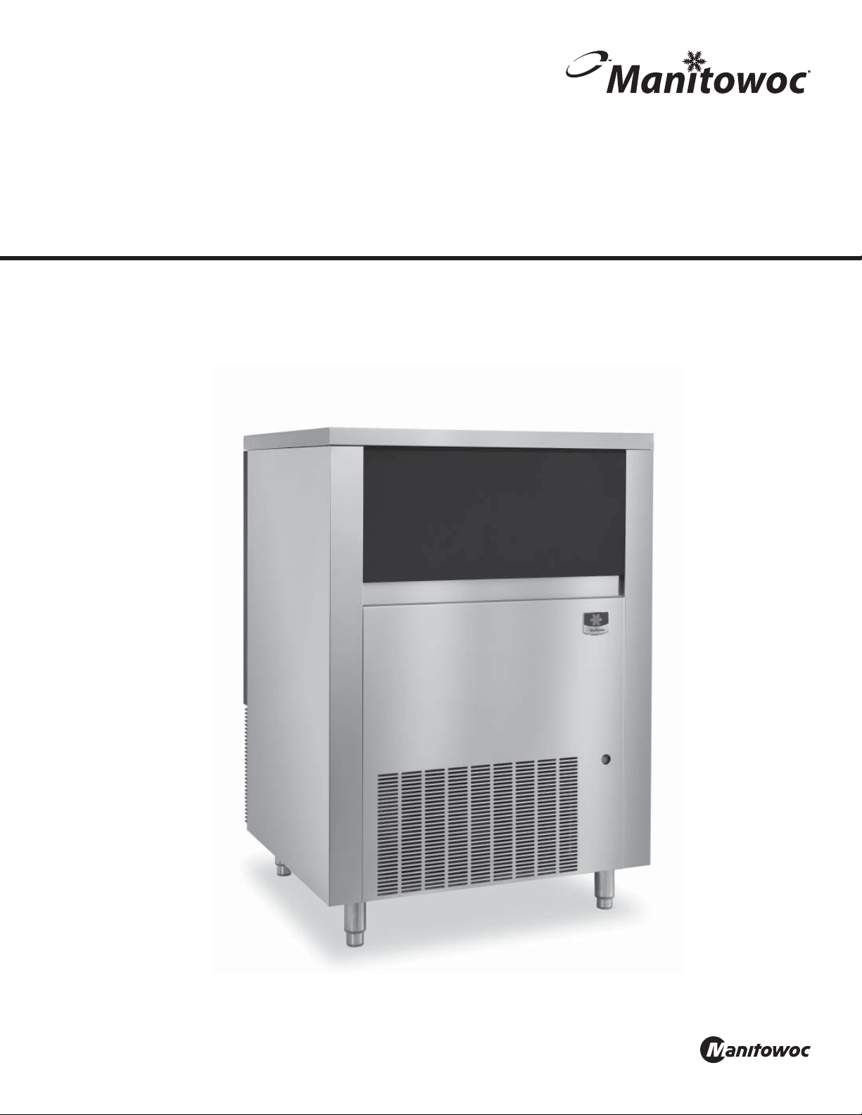
BG Model Ice Machine
Large Gourmet Cube
Installation, Operation and Maintenance Manual
This manual is updated as new information and models are released. Visit our website for the latest manual.
Part Number: 000013398 4/15
Page 2
Safety Notices
DEFINITIONS
DANGER
Indicates a hazardous situation that, if not avoided, will
result in death or serious injury. This applies to the most
extreme situations.
Warning
Indicates a hazardous situation that, if not avoided,
could result in death or serious injury.
Caution
Indicates a hazardous situation that, if not avoided,
could result in minor or moderate injury.
Notice
Indicates information considered important, but not
hazard-related (e.g. messages relating to property
damage).
NOTE: Indicates useful, extra information about the
procedure you are performing.
Warning
Do not operate equipment that has been misused,
abused, neglected, damaged, or altered/modified
from that of original manufactured specifications. This
appliance is not intended for use by persons (including
children) with reduced physical, sensory or mental
capabilities, or lack of experience and knowledge, unless
they have been given supervision concerning use of the
appliance by a person responsible for their safety. Do
not allow children to play with this appliance Do not
allow children to perform cleaning or maintenance with
out supervision.
Warning
All covers and access panels must be in place and
properly secured, before operating this equipment.
Warning
Do not obstruct machine vents or openings.
Warning
Do not store gasoline or other flammable vapors or
liquids in the vicinity of this or any other appliance.
Warning
It is the responsibility of the equipment owner to
perform a Personal Protective Equipment Hazard
Assessment to ensure adequate protection during
maintenance procedures.
Warning
Two or more people are required to move this equipment
to prevent tipping.
Warning
Clean up any water or ice on the floor to prevent personal
injuries. Always inspect for water leakage after cleaning
or maintenance is performed.
Warning
Do not clean with water jet.
Warning
When using electric appliances, basic precautions must
always be followed, including the following:
Do not contact moving parts.
•
Only use attachments recommended or sold by the
•
manufacturer.
Do not use outdoors.
•
Power cord-connections:
•
Do not unplug by pulling on cord. To unplug, grasp
•
the plug, not the cord.
Unplug from outlet when not in use and before
•
servicing or cleaning.
Do not operate any appliance with a damaged cord
•
or plug. Contact the nearest authorized service
facility for examination and repair of electrical cords.
Follow applicable lock out tag out procedures before
•
working on equipment.
Connect to a properly grounded outlet only.
•
Warning
Objects placed or dropped in the bin can affect human
health and safety. Locate and remove any objects
immediately.
Page 3

Warning
Read this manual thoroughly before operating, installing
or performing maintenance on the equipment. Failure
to follow instructions in this manual can cause property
damage, injury or death.
Warning
Do not use electrical appliances or accessories other
than those supplied by Manitowoc for your ice machine
model.
Warning
Two or more people or a lifting device are required to lift
this appliance.
Warning
This equipment contains high voltage electricity and
refrigerant charge. Installation and repairs are to be
performed by properly trained technicians aware of
the dangers of dealing with high voltage electricity and
refrigerant under pressure. The technician must also be
certified in proper refrigerant handling and servicing
procedures. All lockout and tag out procedures must be
followed when working on this equipment.
Warning
Do not damage the refrigeration circuit when installing,
maintaining or servicing the unit.
Caution
Proper installation, care and maintenance are
essential for maximum performance and troublefree operation of your equipment. Visit our website
www.manitowocfsg.com for manual updates,
translations, or contact information for service agents in
your area.
Important
Routine adjustments and maintenance procedures
outlined in this handbook are not covered by the
warranty.
Page 4

THIS PAGE INTENTIONALLY LEFT BLANK
Page 5

Section 1
General Information
Section 2
Installation
Section 3
Operation
Table of Contents
Model Numbers ..................................................................................................................7
Arctic Pure Water Filter System..........................................................................................................7
Location of Ice Machine .....................................................................................................9
Clearances .................................................................................................................................................9
Install Legs and Level ............................................................................................................................9
Electrical Service ..............................................................................................................10
Total Circuit Ampacity .......................................................................................................................10
Electrical Requirements ....................................................................................................................10
Ground Fault Circuit Interrupter .................................................................................................... 10
Power Specifications .......................................................................................................................... 10
Water Supply and Drain Requirements ..........................................................................11
Water Supply ......................................................................................................................................... 11
Water Inlet Lines .................................................................................................................................. 11
Drain Connections .............................................................................................................................. 11
Installation Check List ......................................................................................................11
Section 4
Maintenance
Section 5
Troubleshooting
Sequence of Operation ....................................................................................................13
Freeze Cycle ........................................................................................................................................... 13
Harvest Cycle ........................................................................................................................................13
Automatic Shut-off ............................................................................................................................. 13
Ice Cube Thickness Check ................................................................................................13
Bin Thermostat Adjustment ............................................................................................13
Ice Cube Weight Adjustment ...........................................................................................13
Removal from Service/Long Term Storage/Winterization ............................................ 14
General .................................................................................................................................................... 14
Daily, Weekly Procedures ................................................................................................15
Periodic Maintenance ........................................................................................................................ 15
Cleaning and Sanitizing ...................................................................................................15
General .................................................................................................................................................... 15
Exterior Cleaning ................................................................................................................................. 15
Cleaning/Sanitizing Procedure.......................................................................................................15
Cleaning the Condenser ..................................................................................................17
General .................................................................................................................................................... 17
Troubleshooting Chart ....................................................................................................19
Part Number: 000013398 4/15 5
Page 6

Table of Contents (continued)
THIS PAGE INTENTIONALLY LEFT BLANK
6 Part Number: 000013398 4/15
Page 7

Section 1
General Information
Model Numbers
This manual covers the following ice machines:
Self-Contained
Air-Cooled
BG0260A N/A
Caution
Evaporator construction requires the use of Manitowoc
Metal Safe Cleaner part number 000000084 and
Manitowoc Sanitizer part number 9405653 to prevent
evaporator damage.
Warning
Do not move the ice machine unless all ice has been
removed from the bin.
Self-Contained
Water-Cooled
Dimensions
Model Height Width Depth
BG0260A
Ice Machine Weight
Model Lbs Kg
BG0260A 250 114
Legs
Six inch legs must be installed or the ice machine must be
sealed to the floor.
Decibel Level
Ice machine maximum decibel level is 61 db (A).
ARCTIC PURE WATER FILTER SYSTEM
Engineered specifically for Manitowoc ice machines, This
water filter is an efficient, dependable, and affordable
method of inhibiting scale formation, filtering sediment,
and removing chlorine taste and odor.
42.375 in 33.0 in 29.125 in
1077 mm 838 mm 740 mm
Part Number: 000013398 4/15 7
Page 8

General Information Section 1
THIS PAGE INTENTIONALLY LEFT BLANK
8 Part Number: 000013398 4/15
Page 9

Section 2
Installation
Location of Ice Machine
The location selected for the ice machine must meet the
following criteria. If any of these criteria are not met, select
another location.
• The location must be free of airborne and other
contaminants.
• The air temperature must be at least 50°F (10°C), but
must not exceed 100°F (38°C).
• The water temperature must be at least 50°F (10°C), but
must not exceed 100°F (38°C).
• The location must not be near heat-generating
equipment (ovens, dishwashers, etc.) or in direct
sunlight and must be protected from weather.
• The location must not obstruct air flow through
or around the ice machine. Refer to the clearance
requirement chart.
These ice machines are intended for use in applications
such as:
• Staff kitchen areas in shops, offices and other work
environments.
• Clients in hotels, motels, farmhouses, bed and breakfast
and other residential type environments.
• Catering and similar non-retail applications.
CLEARANCES
Warning
Do not obstruct ice machine vents or openings.
BG0260A
Top 8 in - (203 mm)
Sides 2 in - (51 mm)
Back 2 in - (51 mm)
Warning
The ice machine must be protected if it will be subjected
to temperatures below 32°F (0°C). Failure caused by
exposure to freezing temperatures is not covered by the
warranty.
Warning
To avoid instability the equipment must be installed
in an area capable of supporting the weight of the ice
machine and a full bin of ice. The ice machine must be
level side to side and front to back.
INSTALL LEGS AND LEVEL
Caution
The legs must be screwed in tightly to prevent them
from bending.
1. Screw the leveling legs onto the bottom of the ice
machine.
2. Screw the foot of each leg in as far as possible.
3. Move the ice machine into its final position.
4. Use a level on top of the ice machine. Turn the base of
each foot as necessary to level the ice machine.
Part Number: 000013398 4/15 9
Page 10

Installation Section 2
Electrical Service
Warning
All wiring must conform to local, state and national
codes.
Caution
The maximum allowable voltage variation is ±10% of
the rated voltage at ice machine start-up (when the
electrical load is highest).
Warning
The machine must be grounded in accordance with
national and local electrical codes.
All electrical work, including wire routing and grounding,
must conform to local, state and national electrical codes.
The following precautions must be observed:
• The ice machine must be grounded.
• A separate fuse/circuit breaker must be provided for
each ice machine.
• A qualified electrician must determine proper wire size
dependent upon location, materials used and length
of run (minimum circuit ampacity can be used to help
select the wire size).
• The maximum allowable voltage variation is ±10% of
the rated voltage at ice machine start-up (when the
electrical load is highest).
• Check all green ground screws in the control box and
verify they are tight before starting the ice machine.
TOTAL CIRCUIT AMPACITY
The minimum circuit ampacity is used to help select the
wire size of the electrical supply. (Minimum circuit ampacity
is not the ice machine’s running amp load.)
The wire size (or gauge) is also dependent upon location,
materials used, length of run, etc., so it must be determined
by a qualified electrician.
ELECTRICAL REQUIREMENTS
Refer to Ice Machine Model/Serial Plate for voltage/
amperage specifications.
GROUND FAULT CIRCUIT INTERRUPTER
Ground Fault Circuit Interrupter (GFCI/GFI) protection is
a system that shuts down the electric circuit (opens it)
when it senses an unexpected loss of power, presumably
to ground. Manitowoc Ice does not recommend the use of
a GFCI/GFI circuit protection with our equipment. If code
requires the use of a GFCI/GFI then you must follow the
local code. The circuit must be dedicated, sized properly
and there must be a panel GFCI/GFI breaker. We do not
recommend GFCI/GFI outlets as they are known for more
intermittent nuisance trips than panel breakers.
POWER SPECIFICATIONS
Maximum breaker size is 20 amps.
The wire size to the receptacle is dependent upon location,
materials used, length of run, etc., so it must be determined
by a qualified electrician. Local, state or national
requirements must be followed.
Caution
Observe correct polarity of incoming line voltage.
Incorrect polarity can lead to erratic ice machine
operation. Operate equipment only on the type of
electricity indicated on the specification plate.
10 Part Number: 000013398 4/15
Page 11

Section 2 Installation
Water Supply and Drain Requirements
WATER SUPPLY
Local water conditions may require treatment of the water
to inhibit scale formation, filter sediment, and remove
chlorine odor and taste.
Water inlet fitting - 3/8" FPT
Warning
Connect to a potable water supply only.
WATER INLET LINES
Follow these guidelines to install water inlet lines:
• The water temperature must be at least 50°F (10°C), but
must not exceed 100°F (38°C).
• If you are installing a Manitowoc Arctic Pure® water
filter system, refer to the Installation Instructions
supplied with the filter system for ice making water inlet
connections.
• Do not connect the ice machine to a hot water supply.
Be sure all hot water check valves installed for other
equipment are working. (Check valves on sink faucets,
dishwashers, sprayer nozzles, etc.)
• If water pressure exceeds the maximum recommended
pressure of 80 psi (552 kPa), obtain a water pressure
regulator from your Manitowoc distributor.
• Insulate water inlet lines to prevent condensation.
Caution
Do not apply heat to water valve inlet fitting. This will
damage plastic water inlet connection.
Installation Check List
• Is the Ice Machine level?
• Have all of the electrical and water connections been
made?
• Has the supply voltage been tested and checked against
the rating on the nameplate?
• Is there proper clearance around the ice machine for air
circulation?
• Is the ice machine grounded and polarity correct?
• Has the ice machine been installed where ambient
temperatures will remain in the range of 50° - 100°F
(10° - 38°C)?
• Are all refrigerant lines free from contact with other
components?
• Are all electrical leads free from contact with
refrigeration lines and moving equipment?
• Has the owner/operator been instructed regarding
maintenance and the use of Manitowoc Cleaner and
Sanitizer?
• Has the owner/operator completed the warranty
registration card?
• Have the ice machine and bin been sanitized?
• Is the toggle switch in the on position?
• Has the water sump been primed with a full pitcher of
water?
• Has the cube weight been adjusted to 55 to 61 grams?
NOTE: The ice machine fills the sump in the harvest cycle.
On Initial start or after a cleaning, the sump must be filled
by pouring potable water from a container into the water
sump before starting a freeze cycle.
DRAIN CONNECTIONS
Follow these guidelines when installing the supplied drain
line to prevent drain water from flowing back into the ice
machine storage bin:
Drain fitting - 1/2" MPT
• Drain lines must have a 1.5 inch drop per 5 feet of run
(2.5 cm per meter), and must not create traps.
• The floor drain must be large enough to accommodate
drainage from all drains.
Part Number: 000013398 4/15 11
Page 12

Installation Section 2
THIS PAGE INTENTIONALLY LEFT BLANK
12 Part Number: 000013398 4/15
Page 13

Section 3
Operation
Sequence of Operation
NOTE: The ice machine fills the sump in the harvest cycle.
On Initial start or after a cleaning, the sump must be filled
by pouring potable water from a container into the water
sump before starting a freeze cycle.
FREEZE CYCLE
Turn the toggle switch to on. The compressor and water
pump will energize, starting the freezing cycle. The pump
sprays water into the inverted cups. The water freezes layer
by layer, until an ice cube forms in each cup.
At the same time the compressor starts, the condenser
fan motor is supplied with power throughout the freeze
and harvest cycles. The freeze cycle continues and the
evaporator thermostat reaches the adjusted set point.
HARVEST CYCLE
The compressor continues to operate and the water pump
is de-energized. The hot gas valve energizes, allowing hot
gas from the compressor to enter and warm the evaporator.
The water valve is also energized to aiding with harvest, and
also fills the water sump with fresh water for a new freeze
cycle.
The ice falls from the cups and is directed into the bin by
the ice cube slide. The harvest cycle continues until the
evaporator thermostat changes position.
The hot gas valve and water valve de-energize. If ice cubes
are not contacting the bin thermostat, a new freeze cycle is
initiated as the water pump energizes and sprays water into
the cups.
AUTOMATIC SHUTOFF
When the storage bin is full, the ice will come in contact
with the bin thermostat which is located inside the bin. The
machine will stop when the bin thermostat opens.
The ice machine remains off until enough ice has been
removed from the storage bin to allow bin thermostat to
warm and close, starting another freeze cycle.
Ice Cube Thickness Check
The ice cube thickness is factory-set to maintain the ice
cube thickness at the proper size and weight.
NOTE: A dimple in the end of each cube is normal. Adjusting
to remove the dimple will result in a lower production.
1. Allow the ice machine to operate for three complete
cycles. The cubes should have a small dimple in the
center.
2. Cycle times vary, according to surrounding air and
water inlet temperatures.
3. If cubes are not full (large dimple), turn evaporator
thermostat one increment towards the right to increase
cube size. Allow ice machine to complete three cycles.
Check cube.
4. If cubes are too full, (no dimple), turn evaporator
thermostat one increment towards the left to decrease
cube size. Allow ice machine to operate three complete
cycles.
Bin Thermostat Adjustment
The bin thermostat stops the ice machine when the bin is
full. Turn the thermostat to the left to decrease the level of
ice in bin or to the right to increase the level of ice in bin. If
the ice machine stops before the bin is full or runs after the
bin is full, ambient temperatures are probably high or low
and the bin thermostat can be adjusted.
Ice Cube Weight Adjustment
The cube weight can be increased or decreased from the
factory setting by adjusting the evaporator thermostat.
Turn the thermostat to the left to decrease the cube weight
or to the right to increase the cube weight.
NOTE: To access the bin thermostat or adjust cube weight,
remove the front ice machine panel.
Part Number: 000013398 4/15 13
Page 14

Operation Section 3
Removal from Service/Long Term Storage/
Winterization
GENERAL
Special precautions must be taken if the ice machine is to
be removed from service for an extended period of time or
exposed to ambient temperatures of 32°F (0°C) or below.
Step 1 Perform a cleaning and sanitizing procedure to
prevent mildew growth.
Step 2 Disconnect the electric power cord.
Step 3 Turn off the water supply.
Step 4 Remove the water from the water trough.
Step 5 Disconnect and drain the incoming ice-making
water line at the rear of the ice machine.
Step 6 Disconnect vinyl hose from water pump and allow
to drain.
Step 7 Make sure water is not trapped in any of the water
or drain lines. Compressed air can be used to blow out the
lines.
Step 8 Use a spray bottle and a solution of sanitizer/
water (0.50 oz/ 1 gal) and spray all interior surfaces. Do not
rinse, allow to air dry.
Step 9 Block the door partially open to provide air
exchange and prevent mildew growth.
14 Part Number: 000013398 4/15
Page 15

Section 4
Maintenance
Daily, Weekly Procedures
PERIODIC MAINTENANCE
Maintenance Daily Weekly Monthly Semi Annual Annual After Prolonged
Shutdown
Clean Exterior X X X X X X X
Clean Interior X X X X
Sanitize Interior X X X X X X
At Start-Up
Cleaning and Sanitizing
GENERAL
You are responsible for maintaining the ice machine
in accordance with the instructions in this manual.
Maintenance procedures are not covered by the warranty.
Clean and sanitize the ice machine every month for efficient
operation. If the ice machine requires more frequent
cleaning and sanitizing, consult a qualified service company
to test the water quality and recommend appropriate
water treatment. The ice machine must be taken apart for
cleaning and sanitizing.
Manitowoc Ice Machine Cleaner and Sanitizer are the only
products approved for use in Manitowoc ice machines.
Caution
Damage to the ice machine evaporator caused by
incorrect chemical usage is not covered by the warranty.
Use Manitowoc Ice Machine Cleaner (part number
000000084) and Sanitizer (part number 94-0565-3) only.
Caution
Do not mix Cleaner and Sanitizer solutions together. It
is a violation of Federal law to use these solutions in a
manner inconsistent with their labeling.
EXTERIOR CLEANING
Clean the area around the ice machine as often as necessary
to maintain cleanliness and efficient operation.
Wipe surfaces with a damp cloth rinsed in water to remove
dust and dirt from the outside of the ice machine. If a greasy
residue persists, use a damp cloth rinsed in a mild dish soap
and water solution. Wipe dry with a clean, soft cloth.
The exterior panels have a clear coating that is stain
resistant and easy to clean. Products containing abrasives
will damage the coating and scratch the panels.
• Never use steel wool or abrasive pads for cleaning.
• Never use chlorinated, citrus based or abrasive cleaners
on exterior panels and plastic trim pieces.
CLEANING/SANITIZING PROCEDURE
This procedure must be performed once a month.
• The ice machine and bin must be disassembled cleaned
and sanitized.
• All ice produced during the cleaning and sanitizing
procedures must be discarded.
• Removes mineral deposits from areas or surfaces that
are in direct contact with water.
Warning
Wear rubber gloves and safety goggles (and/or face
shield) when handling Ice Machine Cleaner or Sanitizer.
Part Number: 000013398 4/15 15
Page 16

Maintenance Section 4
Step 1 Open the front door to access the evaporator
compartment. Ice must not be on the evaporator during
cleaning and sanitizing. Follow one of the methods below:
• Press the power switch at the end of a harvest cycle
after ice falls from the evaporator(s).
• Press the power switch and allow the ice to melt.
Caution
Never use anything to force ice from the evaporator.
Damage may result.
Step 2 Remove all ice from the bin and remove top cover
of ice machine.
Step 3 Remove overflow tube and drain water sump.
Step 4 Remove parts for cleaning.
A. Remove two thumbscrews and shutter assembly
B. Remove ice cube slide
C. Remove spray bar and vinyl tubing
D. Evaporator shield on top of evaporator
NOTE: The tubing, spray bar ends and nozzles can be
removed when required for easier cleaning.
Step 5 Mix a solution of cleaner and lukewarm water.
Depending upon the amount of mineral buildup, a larger
quantity of solution may be required. Use the ratio in the
table below to mix enough solution to thoroughly clean all
parts.
Solution Type Water Mixed With
Cleaner 1 gal. (4 L) 16 oz (500 ml) cleaner
Step 6 Use 1/2 of the cleaner/water mixture to clean
all components. The cleaner solution will foam when it
contacts lime scale and mineral deposits; once the foaming
stops use a soft-bristle nylon brush, sponge or cloth (NOT
a wire brush) to carefully clean the parts. All parts except
the ice thickness probe can be soaked when heavily scaled.
Rinse all components with clean water.
Step 7 While components are soaking, use 1/2 of the
cleaner/water solution to clean all foodzone surfaces of
the ice machine and bin. Use a nylon brush or cloth to
thoroughly clean the following ice machine areas:
• Evaporator top panel
• Side walls
• Water trough interior / exterior
• Evaporator and plastic parts - including top, bottom,
and sides
• Bin
Step 8 Rinse all areas thoroughly with clean water.
Step 9 Mix a solution of sanitizer and lukewarm water.
Solution Type Water Mixed With
Sanitizer 3 gal. (12 L) 2 oz (60 ml) sanitizer
Step 10 Use 1/2 of the sanitizer/water solution to sanitize
all removed components. Use a spray bottle to liberally
apply the solution to all surfaces of the removed parts or
soak the removed parts in the sanitizer/water solution. Do
not rinse parts after sanitizing.
16 Part Number: 000013398 4/15
Page 17

Section 4 Maintenance
Step 11 Sanitize all foodzone surfaces of the ice machine
and bin. Use a spray bottle to liberally apply the solution.
When sanitizing, pay particular attention to the following
areas:
• Evaporator top panel
• Side walls
• Water trough interior / exterior
• Evaporator and plastic parts - including top, bottom,
and sides
• Bin
Do not rinse the sanitized areas.
Step 12 Replace all removed components.
NOTE: Spray bar and nozzles.
• If the nozzles were removed from the spray bar, take
care to prevent cross threading when reassembling.
• Verify the spray bar is correctly positioned and the
nozzles are aligned to the evaporator cups.
Step 13 Reapply power to the ice machine and move the
toggle switch to the on position.
Step 14 Discard first batch of ice to remove any flavor
transmission from the cleaning process.
Cleaning the Condenser
GENERAL
Warning
Disconnect electric power to the ice machine by
disconnecting the power cord before cleaning the
condenser.
A dirty condenser restricts airflow, resulting in excessively
high operating temperatures. This reduces ice production
and shortens component life.
• Clean the condenser at least every six months.
Warning
The condenser fins are sharp. Use care when cleaning
them.
• Shine a flashlight through the condenser to check for
dirt between the fins.
• Blow compressed air or rinse with water from the inside
out (opposite direction of airflow).
• If dirt still remains, call a service agent to clean the
condenser.
Part Number: 000013398 4/15 17
Page 18

Maintenance Section 4
THIS PAGE INTENTIONALLY LEFT BLANK
18 Part Number: 000013398 4/15
Page 19

Troubleshooting Chart
Problem Cause Correction
Ice machine does not operate
Ice machine does not release ice
or is slow to harvest
Ice machine produces shallow or
incomplete cubes
Section 5
Troubleshooting
No electrical power to the ice machine Replace the fuse/reset the circuit breaker/turn on the
main switch/plug in the power cord
High pressure cutout tripping Clean the air filter and condenser
Ice machine is not turned on Move the toggle switch to the on position
Ice machine is dirty Clean and sanitize the ice machine
Low air temperature around ice machine Air temperature must be at least 50°F (10°C)
Poor incoming water quality Contact a qualified service company to test the
quality of the incoming water and make appropriate
filter recommendations
Water softener is working improperly (if used) Repair the softener
Cubes too large and ice is forming on
evaporator plastic
Incoming water temperature is too low Water temperature must be 50°F (10°C) or higher
Spray bar or nozzles incorrectly aligned Align nozzles and spray bar
Water filtration is poor Replace filter
Hot incoming water Water must not exceed 90°F (32°C)
Water trough level is low Incorrect incoming water pressure
Verify cube weight is between 55 and 61 grams
Increase water pressure, replace filter, etc. Water
pressure must be 14 - 80 psi (95 kPa - 550 kPa)
Warranty Information
For warranty information visit:
http://www.manitowocice.com/minisite/warranty/default
• Warranty Verification
• Warranty Registration
• View and download a copy of your warranty
Part Number: 000013398 4/15 19
Page 20

Troubleshooting Section 5
THIS PAGE INTENTIONALLY LEFT BLANK
20 Part Number: 000013398 4/15
Page 21

Page 22

Page 23

Page 24

MANITOWOC FOODSERVICE ICE MACHINE DIVISION
2110 SOUTH 26TH STREET, MANITOWOC, WI 54220
8005455720
WWW.MANITOWOCICE.COM
Every new piece of Manitowoc Foodservice equipment comes with KitchenCare® and you choose the level of service that meets
your operational needs from one restaurant to multiple locations.
StarCare – Warranty & lifetime service, certi ed OEM parts, global parts inventory, performance audited
ExtraCare – CareCode, 24/7 Support, online/mobile product information
LifeCare – Install & equipment orientation, planned maintenance, KitchenConnect™, MenuConnect
Talk with KitchenCare® • 1-844-724-CARE • www.mtwkitchencare.com
To learn how Manitowoc Foodservice and its leading brands can equip you, visit our global web site at
www.manitowocfoodservice.com, then discover the regional or local resources available to you.
©2015 Manitowoc Foodservice except where explicitly stated otherwise. All rights reserved. Continuing product improvement may necessitate change of speci cations without notice.
Part Number: 000013398 4/15
 Loading...