

Page 1
10 1/4
(260.4)
5/8
(15.9)
10 3/16
(258.8)
12 15/16
(328.6)
11 1/4
(285.8)
7 13/16
(198.4)
8 13/16
(223.8)
4 3/16
(106)
1/4
(6.4)
7 1/2
(190.5)
6 1/8
(155.6)
1/2 (12.7) Hose Barb
1/4 (6.4) NPT Optional
1/2 (12.7) Hose Barb
1/4 (6.4) NPT Optional
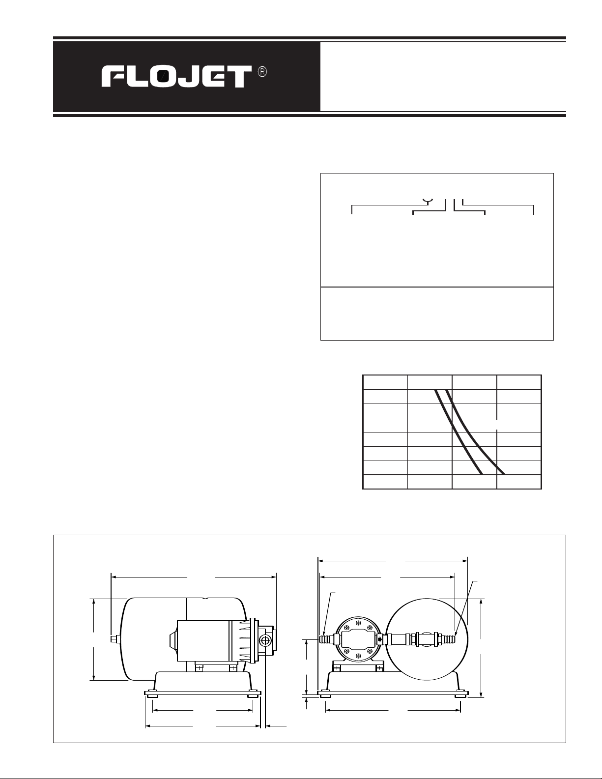
2820 Series
28 X X - X X X
20 = Duplex 0 = 115V AC 4 = 70 PSI 0 = Std
(2130) 2 = 230V AC
Pump Service
Voltage
Switch Options
0 PSI Inlet
40
(2.8)
20
(1.4)
30
(2.1)
80
(5.5)
50
(3.4)
60
(4.1)
70
(4.8)
10
(0.7)
1.0
(3.8)
0.5
(1.9)
1.5
(5.7)
Flow in GPM (l/min)
Note: Flow readings are nominal
Pressure in PSI (bar)
0
10 PSI Inlet
Booster Pump System
FOR MODELS 2820-040 115 VOLTS AC
FOR MODELS 2820-240 230 VOLTS AC
PRODUCT DATA
Pump Design ............................................Duplex Diaphragm
Motor ................
Permanent Magnet ............................TENV
Wetted Parts ....Diaphragm Material ..........................EPDM
Check Valve Material ........................EPDM
Housing Material ................................Nylon
Accumulator Tank
Diaphragm Material ............................Butyl
Liner Material ..........................Polpropylene
Ports ..........................................................................1/4” NPT
Net Weight ..............................................7.4 Pounds (3.4 kgs)
PERFORMANCE SPECIFICATIONS
PUMP
Motor
Liquid Temperature
Priming ..............Dry ............................................5 ft. (1.5 m)
Flow Rate ..........Max ....................1.5 GPM @ 0 PSI (0.0 bar)
Pressure Switch
Timer ................. ..............................3 minute, manual reset
TANK
Total Volume
Operating Volume ......................................0.22 Gal. (0.8 Lt.)
................Max Amp Draw ..................0.55 @ 115 VAC
0.25 @ 230 VAC
Cycle ........................................50160 Hertz
Min ................................................45° (7°C)
Max ..........................................160°F (71°C)
Wet ..........................................15 ft. (4.6 m)
Off ......................................70 PSI (4.8 bar)
On ......................................45 PSI (3.1 bar)
..................................................1.1 Gal. (4.1 Lt.)
2820 Series Booster Pump System
STANDARD MODEL NUMBERING SYSTEM
The standard model numbering system is used for models up
to -500. Numbers -500 and over are used for variations from
standard assemblies such as special pump or tank
specifications. Consult the factory for special models to meet
specific requirements.
PERFORMANCE FOR AC MODELS
Dimensional Drawing
Inches (millimeters)
Page 2
GENERAL SAFETY INFORMATION
Inlet
Strainer
1/2” NPT
Pressure
Out
Optional
Regulator
If Required
Water
Supply
Protect yourself and others by observing all safety
information. Shut of
f power and drain pressure from
system prior to service.
DESCRIPTION
The FLOJET 2820 series Booster Pump Systems are
designed to provide a constant water pressure of 45 to
70 psi (3.1 - 4.8 bar) and maximum flow of 1.5 GPM at
10 psi (0. 7 bar). The pump is fully automatic with a builtin switch and check valve to maintain system pressure
and will supply smooth water flow from a trickle to full
flow. Typical uses are; Commercial Ice Machines, Pure
Water Dispensing, Water Purifiers, Small Domestic and
Commercial Appliances where the water supply
pressure is very low or fluctuates widely.
OPERATION
IMPORTANT - For correct operation, the tank must be
properly pressurized on the air side
started. Follow instructions on the tank label and check air
pressure after filling and before starting the pump. The
air valve is a standard tire valve. Compressed air hose
or hand pump may be used to pressurize. Pressure can
be reduced by pressing the center pin in the valve.
Make sure pump inlet connection is securely connected
to the water supply and no inlet valves are open. Open
all valves or taps on outlet side to purge air from the
system. Turn power on to the pump, pump will start up.
Allow system to pump for a minute or until all the air has
been purged from the system. Close all valves in the
system, the pump will pressurize the tank, shut off and
operate automatically to maintain pressure In the system.
before the pump is
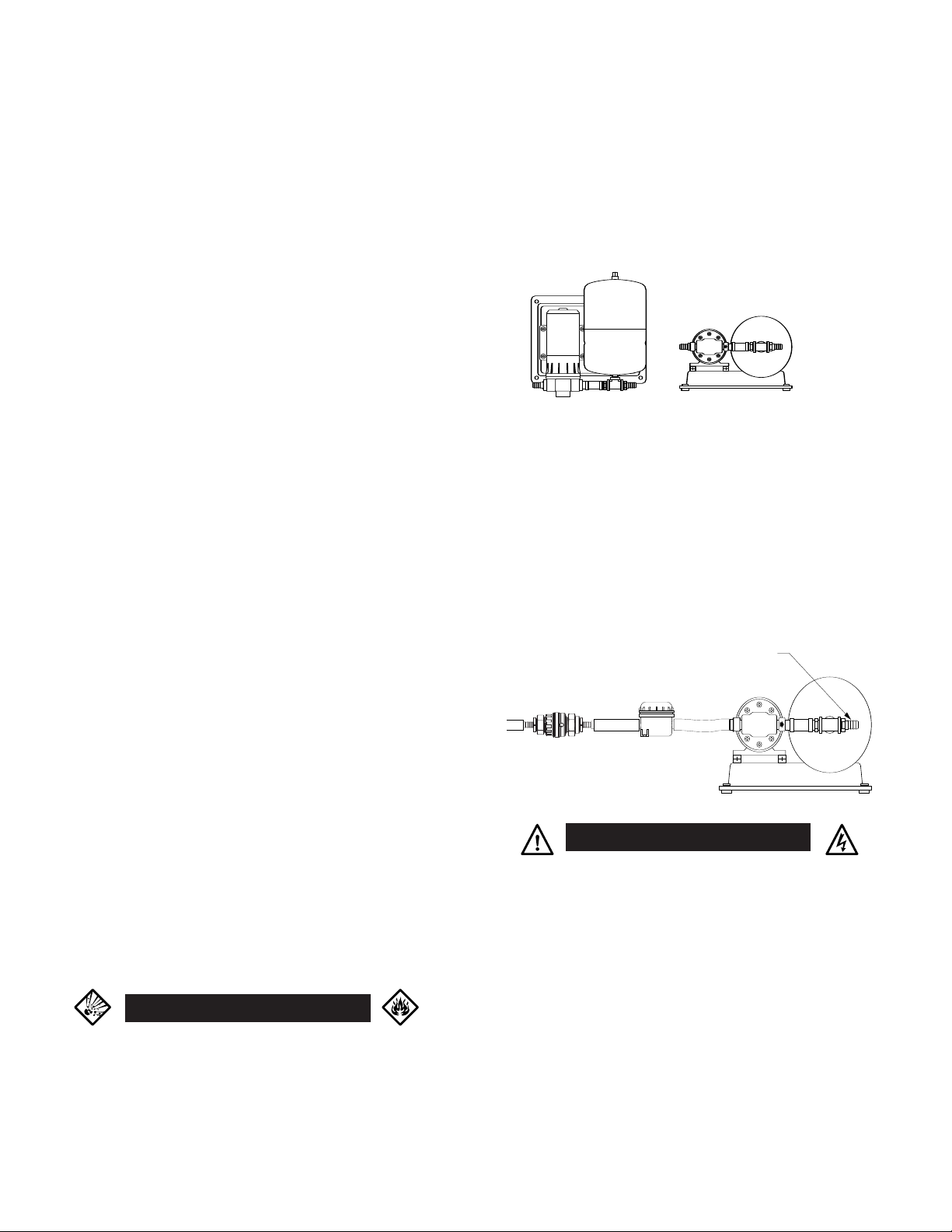
MOUNTING
The FLOJET 2820 Series Water Pressure System should
be mounted in a dry and adequately ventilated ar
ea.
Select a location where the plumbing is as direct as
possible and the inlet strainer is visible and accessible
for cleaning.
The unit can be floor or wall mounted. If wall mounted,
the Pump head should be down or lower than the motor
Fasten base securely with the four rubber mounting feet
assembled to base as shown below.
Vertical Horizontal
PLUMBING
Fasten strainer in a visible and accessible location for
future cleaning. Use 1/2” ID hose between pump inlet &
strainer. Connect strainer inlet (1/2” hose) to water
supply line and clamp all hose connections securely to
avoid air leaks. IMPORTANT - if water supply line has
pressure fluctuations that may exceed 30 psi (2.1 bar) use a pressure regulator to limit inlet pressure to 30 psi
(2.1 bar) maximum, such as Flojet 1750 series.
Regulator may be installed at any convenient location
between water supply and inlet strainer.
.
To completely fill the pressure tank for maximum
volume, shut off power to pump and open faucet (or valve)
closest to tank. Trapped air will be expelled. Turn on
power to pump and close faucet when water is free of air.
WINTERIZING TIP
When units are exposed to freezing conditions.
1. Open discharge valve (Faucet nearest to the
Booster System).
Open inlet side to pump (Remove inlet hose to the
2.
Booster System).
3. Run Pump for approximately 2 minutes, (Dry) or
until system is out of fluid.
Leave discharge. value open and inlet hose
4.
removed until next usage.
ARNING
WWARNING
DO NOT USE PUMP IN A FLAMMABLE
ENVIRONMENT. DO NOT USE TO PUMP
FLAMMABLE OR EXPLOSIVE FLUIDS
SUCH AS GASOLINE, FUEL OIL,
KEROSENE, ETC.
ELECTRICAL
WARNING
RISK OF AN ELECTRICAL SHOCK!
When wiring an electrically driven pump, follow all
electrical and safety codes, as well as the most r
National Electrical Code (NEC) and the Occupational
Safety and Health Act (OSHA).
RISK OF PRODUCT DAMAGE!
Make certain the power source conforms to the pump
voltage. Be sure all power is disconnected before
installation or r
Use the maximum r
protection. Recommended fuse amp rating is located
on pump label. Failur
device may r
For 115V AC plug AC cord into a conventional 115V AC outlet.
emoval.
ecommended fuse for pump
e to provide correct overload
esult in motor failur
e.
ecent
Page 3

7
1
58 Includes items 1 thru 5
E
6
4
D G FCBA
2
3
W
ARNING: DISCONNECT POWER TO PUMP AND OPEN VALVE TO
!!
RELIEVE WATER PRESSURE PRIOR TO SERVICING PUMP
Key Part No. Description Qty
1 20131-001 Pump Screws Kit, Set of 6 1
20316-100 Upper Housing w/ Switch 1
2
3 20028-053 EPDM CVA Kit
4 21023-132A Lower Housing Kit 1
5 20552-000 Cam Bearing Set Screw 1
6 02029-014A 115V AC Motor 1
02039-007A 230V AC Motor
7 11028-101 Plastic Baseplate Kit 1
w/ Grommets & Screws
DISASSEMBLE
Upper Housing (2)
1. Disconnect power to pump and open faucet or valve to
relieve system pressure.
2. Remove the six Pump Head Screws (1) located on top of the
Upper Housing Housing (2).
Check Valve (3) Follow steps 1 and 2
3. The Check Valve (3) is locate in the Upper Housing (2), or on
the Diaphragm (4-B). Remove Check V
Lower Housing (4-C) Follow steps 1 and 2
4. Rotate Lower Housing (4-C), so access notch is aligned with
Cam Bearing Set Screw (5), loosen set screw with a 1/8”
Allen W
Cam Bearing (4-F) Follow steps 1 thr
Rotate Lower Housing (4-C) to view Cam Bearing Assembly
5.
(4-F).
Remove both Phillips Head Scr
6.
Bearing (4-F) to the Outer Pistons (4-D).
Inner and Outer Pistons (4A & 4D) Follow steps 1 thr
7. After removing the Cam Bearing from the Outer Pistons, the
Inner Pistons are visible. Remove both Flat Head Screws.
The Inner Pistons pop-out.
Diaphragm (4-B) Follow steps1 through 8
ench and slide pump head of
r
alve (3).
f motor shaft.
ough 5
ews that attach the Cam
ough 7
Key Part No. Description Qty
8 21054-591 Pump Head Assy. 2820-040 1
21054-592 Pump Head Assy. 2820-240
** 02130-591A Complete MPU 1
02130-592A Complete MPU
** 20799-000A Accumulator Tank
** 20796-000A Base
** 01740-003 Strainer
**Not Shown in Diagram
For Model 2820-040
For Model 2820-240
REASSEMBLE
Diaphragm (4-B)
1. Place hex stem of Inner Pistons (4-A) through Diaphragm (4-B),
and openings in Lower Housing (4-C) and into Inner Pistons
(4-A).
2. Center Pistons in Diaphragm and tighten Flat Head Screws
(4-E).
Cam Bearing (4-D)
3. Place Cam Bearing (4-D) over Outer Pistons (4-D), align
locating pins in the hole of the Cam Bearing.
4. Install round head screws and tighten securely.
Lower Housing (4-C)
Coat motor shaft with gr
(4-F).
5. Attach Cam Bearing (4-F) to motor shaft indentation by Cam
Bearing Set Scr
rotate access notches down towards the Baseplate (7).
Check Valve (3)
6. Install Check Valve with new O-Ring over the, Pistons (4-A) in
Diaphragm (4-B) dischar
up.)
7. Join Upper Pump Housing (2) with Lower Housing (4-C) by six
Pump Head Scr
Upper Housing (2) Follow steps 6 thr
ew (5). When installing the Lower Housing,
ews (1).
ease prior to installing Cam Bearing
ge side up. (Side with center cir
ough 7
cle
Page 4

TROUBLESHOOTING CHART
Symptom Possible Cause(s) Corrective Action
Pump will not prime or retain • Air leak in suction line • Repair or replace
prime after operating (When pump is
above tank or cistern water supply) • Upper housing leaking • Tighten bolts
Pump runs but no fluid • Faulty suction piping • Repair or replace
Motor runs too hot • Voltage incorrect • Check voltage
Flow rate is low • Piping or hose is damaged • Clean or replace
Pump leaks • Upper housing loose • Tighten screws
Pump will not run • No electricity • Check connections, fuse, breakers
• Defective check valve • Replace
• Suction lift too high • Lower pump
• Debris in check valve(s)
• Clean check valve(s)
• Defective check valve • Replace
• Suction lift too high • Lower pump
• Clogged inlet • Clean or replace
• Inlet line valve closed • Open valve
• Insufficient ventilation for motor • Insure proper ventilation
• Clogged check valve • Clear obstruction
• Worn check valve • Replace
• Voltage incorrect • Check voltage
• Pistons loose • Tighten piston screws
• Diaphragm Failure • Replace
• Switch loose • Tighten switch
• Defective pressure switch • Replace switch
• Motor has open circuit • Replace
CONVERSION TABLE
TO CONVERT TO MULTIPLY BY
Gallons, U.S. Liters 3.785
Liters Gallons, U.S. 0.264
Pounds/Sq. Inch Bar 0.069
Bar Pounds/Sq. Inch 14.5
Fahrenheit Celsius (°F-32) .556
Celsius Fahrenheit (°C X 1.8) + 32
WARRANTY
FLOJET warrants this product to be free of defects in material and/or
workmanship for a period of one year after purchase by the customer
from FLOJET. During this one year warranty period, FLOJET will at its
option, at no charge to the customer, repair or replace this product if
found defective, with a new or reconditioned product, but not to
include costs of removal or installation. No product will be accepted
for return without a return material authorization number. All return
goods must be shipped with transportation charges prepaid. This is
only a summary of our Limited Warranty. For a copy of our complete
warranty, please request Form No. 100-101.
U.S.A.
Flojet
20 Icon
Foothill Ranch, CA 92610
RETURN PROCEDURE
Prior to returning any product to FLOJET, call customer service for an
authorization number. This number must be written on the outside
of the shipping package. Place a note inside the package with an
explanation regarding the reason for return as well as the
authorization number. Include your name, address and phone number.
UNITED KINGDOM
Flojet
Bingley Road, Hoddesdon
Hertfor
e EN11 OBU
dshir
www.flojet.com
Copyright 2005, ITT Industries
Tel: 949.859.4945
949.859.1153
Fax:
Printed in U.S.A.
Tel: +44 (0) 1992 450145
+44 (0) 1992 467132
Fax:
All Rights Reserved
Form: 82000-012
. C 10/2005
Rev
 Loading...