

Page 1
Service Manual
Garland GT Series
US Range UT Series
Heavy Duty Gas
Counter Equipment
TM
FOR YOUR SAFETY
DO NOT store or use gasoline or other flammable vapors or liquids in the vicinity of this or any other
appliance
WARNING
Improper installation, adjustment, alteration, service or maintenance can cause property damage,
injury, or death. Read the installation, operating and maintenance instructions thoroughly before
installing or servicing this equipment.
IMPORTANT
Please read all sections of this manual and retain for future reference.
This product has been certified as commercial cooking equipment and must be installed by
professional personnel as specified.
Users are cautioned that maintenance and repairs must be performed by a Garland/US Range
Authorized Service Agent using genuine Garland replacement parts. Garland/US Range will have no
obligation with respect to any product that has been improperly installed, adjusted, operated or not
maintained in accordance with national and local codes or installation instructions provided with
the product, or any product that has its serial number defaced, obliterated or removed, or which has
been modified or repaired using unauthorized parts or by unauthorized service agents. For a list of
authorized service agents, please refer to the Garland web site at www.garland-group.com
Garland Commercial Ranges, Ltd.
1177 Kamato Road
Mississauga, Ontario L4W 1X4 Canada
General Inquiries P: 905 624 0260 F: 905 624 5669
www.Garland-Group.com
Parts & Service
1 800 427 6668 (Phone, US & Canada)
1 800 361 7745 (Fax, US & Canada)
A_GC_SM_HDGASCOUNTERSERV_GT-UT-SERIES (Rev 1)
Page 2

Safety Requirements
WARNING
This product contains chemicals known to the state of California to cause cancer and/or birth defects or
other reproductive harm. Installation and servicing of this product could expose you to airborne particles of
glass wool/ceramic fibers. Inhalation of airborne particles of glass wool/ceramic fibers is known to the State
of California to cause cancer. Operatin of this product could expose you to carbon monoxide if not adjusted
properly. Inhalation of carbon monoxide is known to the State of California to cause birth defects or other
reporductive harm.
WARNING
Before working on any appliance, Shut Off the gas supply at the main shut-off valve and electrical supply at the
main power switch. On completion of any service work, test for gas leaks before returning the equipment into
service.
IMPORTANT
Please read and follow all the instructions carefully as the manufacturer cannot be held responsible for any
damage to property, persons caused by incorrect installation or operation of the equipment.
Your equipment must be installed and adjusted by a competent person in accordance with the law. Failure to
install appliances correctly could lead to prosecution. It is in your own interest and that of safety to ensure that
the law is complied with. Refer to Garland/US Range Installation And Operation Manual for further details.
Your Garland/US Range Authorized Service Agent (ASA) is well qualified to provide this service.
Periodic inspections by your Garland/US Range ASA or qualified service company are recommended to check
temperatures, burner adjustments and to ensure that moving parts are operative. Whenever possible avoid
overheating idle equipment as this is the primary cause for increased service cost.
NOTE
This manual is written for the model(s) specified on the front cover. Unless specified, this manual should not be
used for any other make or model of appliance.
Garland reserves the right to change product specifications without notices and accepts no liability for any
inaccuracies, errors or ommissions contained herein.
Keep your working area free and clear.
Remember Safety First.
A_GC_SM_HDGASCOUNTERSERV_GT-UT-SERIES (Rev 1)Page 2
Page 3

Contents
Safety Requirements . . . . . . . . . . . . . . . . . . . . . . . . . . . . . . . . . . . . . . . . . . . . . . . . . . . . . . . . . . . . . . . . . . . . .2
Rating Plate, Serial Number Information . . . . . . . . . . . . . . . . . . . . . . . . . . . . . . . . . . . . . . . . . . . . . . . . . . . . .4
Model Code Information . . . . . . . . . . . . . . . . . . . . . . . . . . . . . . . . . . . . . . . . . . . . . . . . . . . . . . . . . . . . . . . . . .5
Technical Data . . . . . . . . . . . . . . . . . . . . . . . . . . . . . . . . . . . . . . . . . . . . . . . . . . . . . . . . . . . . . . . . . . . . . . . . . .6
General Pilot Procedures . . . . . . . . . . . . . . . . . . . . . . . . . . . . . . . . . . . . . . . . . . . . . . . . . . . . . . . . . . . . . . . . 15
Lighting Standing Pilots - All Models 15
Open Top Burner Models 15
Broilers Models 15
Griddles with Valve Controls 15
Griddles with SIT Thermostats 16
Griddles with GS Thermostats 16
Shutdown Procedure 16
Shutdown Procedure on Griddles with SIT Thermostats 16
Gas Pressure Regulator . . . . . . . . . . . . . . . . . . . . . . . . . . . . . . . . . . . . . . . . . . . . . . . . . . . . . . . . . . . . . . . . . 17
Rear Gas Pressure Regulator Connection Options 17
Purpose of gas pressure regulator 17
Open Top Burners Adjustments . . . . . . . . . . . . . . . . . . . . . . . . . . . . . . . . . . . . . . . . . . . . . . . . . . . . . . . . . . 18
Pilot Adjustment Valves 18
Burner Gas / Air Shutter Adjustment 18
Troubleshooting — Open Top Burners. . . . . . . . . . . . . . . . . . . . . . . . . . . . . . . . . . . . . . . . . . . . . . . . . . . . . 19
Griddle Adjustments . . . . . . . . . . . . . . . . . . . . . . . . . . . . . . . . . . . . . . . . . . . . . . . . . . . . . . . . . . . . . . . . . . . 20
Griddle Spark Igniter 20
High Tension Lead (HTL) & Insulation 21
Thermostatic Griddle Adjustments (SIT Control) 22
Thermostatic Griddle Adjustments (GS Control) 26
Griddles with Hi/Low Valves 28
Troubleshooting — Griddles. . . . . . . . . . . . . . . . . . . . . . . . . . . . . . . . . . . . . . . . . . . . . . . . . . . . . . . . . . . . . 29
Broiler Adjustments . . . . . . . . . . . . . . . . . . . . . . . . . . . . . . . . . . . . . . . . . . . . . . . . . . . . . . . . . . . . . . . . . . . . 30
Pilot Adjustment Valves 30
Gas Burner Control Valves 30
Burner Gas / Air Shutter Adjustment 31
Troubleshooting — Broilers . . . . . . . . . . . . . . . . . . . . . . . . . . . . . . . . . . . . . . . . . . . . . . . . . . . . . . . . . . . . . 32
Wiring Diagram (GTGG/UTGG__M Models Electric Spark) . . . . . . . . . . . . . . . . . . . . . . . . . . . . . . . . . . . . . 34
Wiring Diagram (GTGG/UTGG Electric Spark) . . . . . . . . . . . . . . . . . . . . . . . . . . . . . . . . . . . . . . . . . . . . . . . 35
Gas Conversion Kits (from Natural to Propane). . . . . . . . . . . . . . . . . . . . . . . . . . . . . . . . . . . . . . . . . . . . . . 36
Gas Conversion Kits (from Propane to Natural). . . . . . . . . . . . . . . . . . . . . . . . . . . . . . . . . . . . . . . . . . . . . . 37
Bulletins & Revision History. . . . . . . . . . . . . . . . . . . . . . . . . . . . . . . . . . . . . . . . . . . . . . . . . . . . . . . . . . . . . . 38
A_GC_SM_HDGASCOUNTERSERV_GT-UT-SERIES (Rev 1) Page 3
Page 4
Rating Plate, Serial Number Information
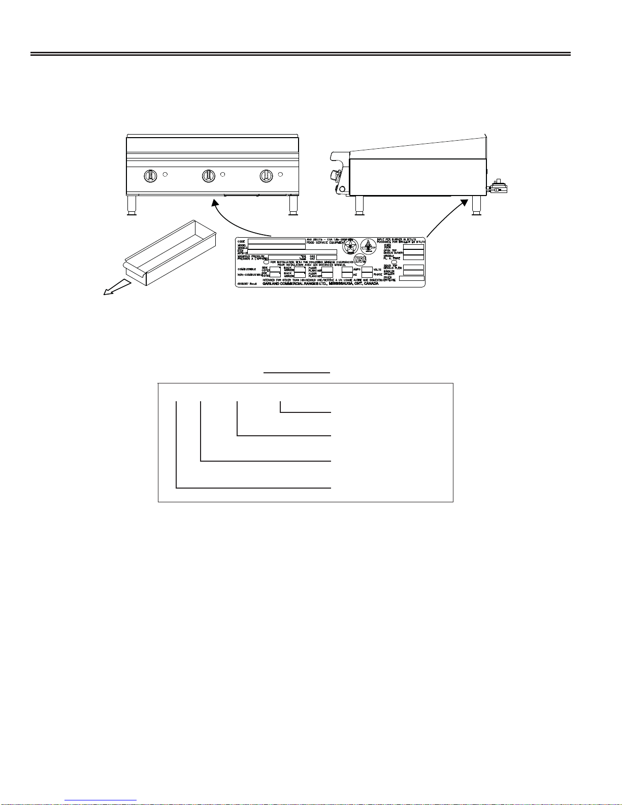
Rating Plate
The rating plate is affixed to a bracket mounted at the rear of the unit, and visible from the front. The grease drawer
may need to be removed to view the rating plate.
Serial Number (Year/Month Information)
From June 2004 to Present, the Serial Number is 13 Digits Long.
10 05 1001 00668
Sequential Number
Factory Code
Month
Year
A_GC_SM_HDGASCOUNTERSERV_GT-UT-SERIES (Rev 1)Page 4
Page 5

Model Code Information
Open Top Models:
• GTOG__-_ / UTOG__-_ Open Top Model
• GTOG__-SU_ / UTOG__-SU_ Open Top Step-Up Model
GT/UT O G 36 - 6
Number of Burners, or
SU (Step-Up) + Number of Burners
Nominal Width of Equipment
Fuel Type: Gas (Propane or Natural), Electric
Open Burner
Garland/US Range Heavy Duty Counter Top Model
Griddle Models:
• GTGG__-G__ / UTGG__-G__ Valve-Controlled Griddle Model (out-of-production)
• GTGG__-G__M / UTGG__-G__M Valve-Controlled Griddle Model with Suffix M
• GTGG__-GT__ / UTGG__-GT__ Thermostat-Controlled Griddle Model (out-of-production)
• GTGG__-GT__M / UTGG__-GT__M Thermostat-Controlled Griddle Model with Suffix M
GT/UT G G 48 - G 48 M
Models with Suffix M
Model Size
Griddle with Hi-Low Valve Control, or
GT - Thermostatic Griddle
Nominal Width of Equipment
Fuel Type: Gas (Propane or Natural), Electric
Griddle
Garland/US Range Heavy Duty Counter Top Model
Broiler Models:
• GTBG__-NR__ / UTBG__-NR__ Non-Adjustable (Fixed) Radiant Broiler Model
• GTBG__-AR__ / UTBG__-AR__ Adjustable Radiant Broiler Model
• GTBG__-AB__ / UTBG__-AB__ Adjustable Charcoal Broiler Model
GT/UT B G 48 - AR 48
Model Size
NR - Non-Adjustable (Fixed) Radiant
AR - Adjustable Radiant
AB - Adjustable Charcoal Broiler
Nominal Width of Equipment
Fuel Type: Gas (Propane or Natural), Electric
Broiler
Garland/US Range Heavy Duty Counter Top Model
A_GC_SM_HDGASCOUNTERSERV_GT-UT-SERIES (Rev 1) Page 5
Page 6
Technical Data
Model Information
Garland Models US Range Models Model Information
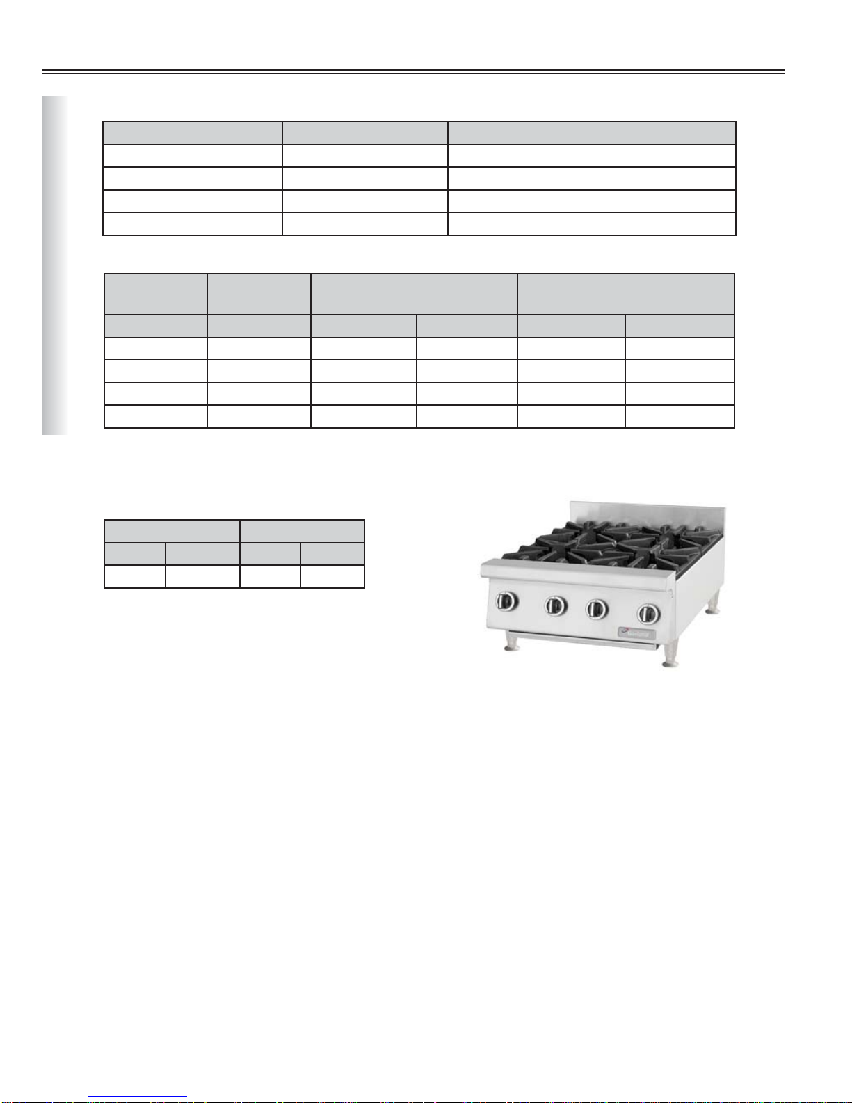
GTOG12-2 UTOG12-2 Gas, Two Open Burners, 12” Wide
GTOG24-4 UTOG24-4 Gas, Four Open Burners, 24” Wide
GTOG36-6 UTOG36-6 Gas, Six Open Burners, 36” Wide
GTOG48-8 UTOG48-8 Gas, Eight Open Burners, 48” Wide
Line Ratings
Garland US Range Natural Gas @ 4.5”WC
Manifold Pressure
Models Models BTU/h Injectors BTU/h Injectors
GTOG12-2 UTOG12-2 60,000 #36 52,000 #53
GTOG24-4 UTOG24-4 120,000 #36 104,000 #53
Open Top Burner Models
For use with Natural or Propane gas only.
Gas input ratings shown for installation up to 2000 ft (610m) above sea level.
Supply Operating Pressure
GTOG36-6 UTOG36-6 180,000 #36 156,000 #53
GTOG48-8 UTOG48-8 240,000 #36 208,000 #53
Natural Gas Propane Gas
“WC MBar “WC MBar
7 17.5 11 27.5
L. Propane Gas @ 10”WC
Manifold Pressure
A_GC_SM_HDGASCOUNTERSERV_GT-UT-SERIES (Rev 1)Page 6
GTOG24-4 Shown
Page 7
Technical Data
Model Information
Garland Models US Range Models Model Information
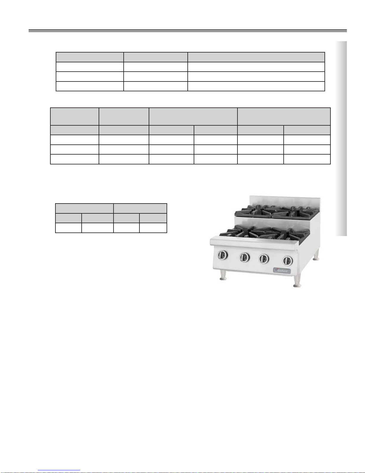
GTOG24-SU4 UTOG24-SU4 Gas, Four Open Burners Step Up, 24” Wide
GTOG36-SU6 UTOG36-SU6 Gas, Six Open Burners Step Up, 36” Wide
GTOG48-SU8 UTOG48-SU8 Gas, Eight Open Burners Step Up, 48” Wide
Line Ratings
Open Top Burner Step-Up Models
Garland US Range Natural Gas @ 4.5”WC
Manifold Pressure
Models Models BTU/h Injectors BTU/h Injectors
GTOG24-SU4 UTOG24-SU4 120,000 #36 108,000 #1.6mm
GTOG36-SU6 UTOG36-SU6 180,000 #36 162,000 #1.6mm
GTOG48-SU8 UTOG48-SU8 240,000 #36 216,000 #1.6mm
For use with Natural or Propane gas only.
Gas input ratings shown for installation up to 2000 ft (610m) above sea level.
Supply Operating Pressure
Natural Gas Propane Gas
“WC MBar “WC MBar
7 17.5 11 27.5
L. Propane Gas @ 10”WC
Manifold Pressure
GTOG24-SU4 Shown
A_GC_SM_HDGASCOUNTERSERV_GT-UT-SERIES (Rev 1) Page 7
Page 8
Technical Data
Model Information
Garland Models US Range Models Model Information
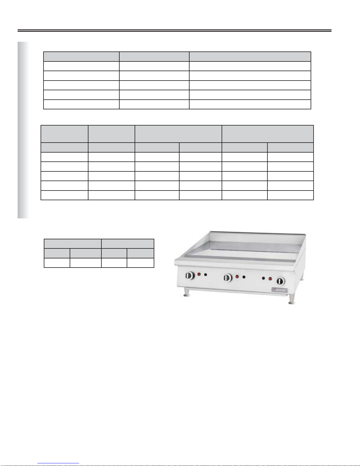
GTGG24-G24 UTGG24-G24 Gas, Valve Controlled Griddle, 24” Wide
GTGG36-G36 UTGG36-G36 Gas, Valve Controlled Griddle, 36” Wide
GTGG48-G48 UTGG48-G48 Gas, Valve Controlled Griddle, 48” Wide
GTGG60-G60 UTGG60-G60 Gas, Valve Controlled Griddle, 60” Wide
GTGG72-G72 UTGG72-G72 Gas, Valve Controlled Griddle, 72” Wide
Line Ratings
Garland US Range Natural Gas @ 4.5”WC
Manifold Pressure
Models Models BTU/h Injectors BTU/h Injectors
GTGG24-G24 UTGG24-G24 52,000 #37 52,000 #53
GTGG36-G36 UTGG36-G36 78,000 #37 78,000 #53
GTGG48-G48 UTGG48-G48 104,000 #37 104,000 #53
GTGG60-G60 UTGG60-G60 130,000 #37 130,000 #53
GTGG72-G72 UTGG72-G72 156,000 #37 156,000 #53
Valve Controlled Griddle Models
For use with Natural or Propane gas only.
Gas input ratings shown for installation up to 2000 ft (610m) above sea level.
Supply Operating Pressure
Natural Gas Propane Gas
“WC MBar “WC MBar
7 17.5 11 27.5
L. Propane Gas @ 10”WC
Manifold Pressure
A_GC_SM_HDGASCOUNTERSERV_GT-UT-SERIES (Rev 1)Page 8
GTGG36-G36 Shown
Page 9
Technical Data
Model Information
Garland Models US Range Models Model Information
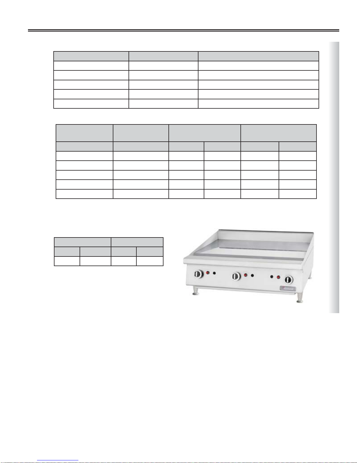
GTGG24-G24M UTGG24-G24M Gas, Valve Controlled Griddle, 24” Wide
GTGG36-G36M UTGG36-G36M Gas, Valve Controlled Griddle, 36” Wide
GTGG48-G48M UTGG48-G48M Gas, Valve Controlled Griddle, 48” Wide
GTGG60-G60M UTGG60-G60M Gas, Valve Controlled Griddle, 60” Wide
GTGG72-G72M UTGG72-G72M Gas, Valve Controlled Griddle, 72” Wide
Line Ratings
Garland US Range Natural Gas @ 4.5”WC
Manifold Pressure
Models Models BTU/h Injectors BTU/h Injectors
GTGG24-G24M UTGG24-G24M 54,000 #35 54,000 #52
GTGG36-G36M UTGG36-G36M 81,000 #35 81,000 #52
GTGG48-G48M UTGG48-G48M 108,000 #35 108,000 #52
GTGG60-G60M UTGG60-G60M 135,000 #35 135,000 #52
GTGG72-G72M UTGG72-G72M 162,000 #35 162,000 #52
For use with Natural or Propane gas only.
Gas input ratings shown for installation up to 2000 ft (610m) above sea level.
L. Propane Gas @ 10”WC
Manifold Pressure
Valve Controlled Griddle Models (with Suffix M)
Supply Operating Pressure
Natural Gas Propane Gas
“WC MBar “WC MBar
7 17.5 11 27.5
GTGG36-G36M Shown
A_GC_SM_HDGASCOUNTERSERV_GT-UT-SERIES (Rev 1) Page 9
Page 10
Technical Data
Model Information
Garland Models US Range Models Model Information
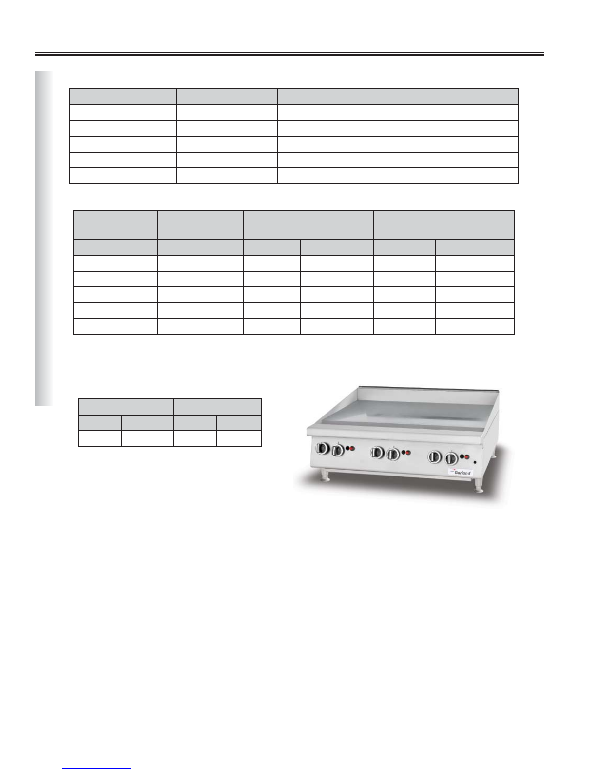
GTGG24-GT24 UTGG24-GT24 Gas, Thermostatically Controlled Griddle, 24” Wide
GTGG36-GT36 UTGG36-GT36 Gas, Thermostatically Controlled Griddle, 36” Wide
GTGG48-GT48 UTGG48-GT48 Gas, Thermostatically Controlled Griddle, 48” Wide
GTGG60-GT60 UTGG60-GT60 Gas, Thermostatically Controlled Griddle, 60” Wide
GTGG72-GT72 UTGG72-GT72 Gas, Thermostatically Controlled Griddle, 72” Wide
Line Ratings
Garland US Range Natural Gas @ 4.5”WC
Manifold Pressure
Models Models BTU/h Injectors# BTU/h Injectors#
GTGG24-GT24 UTGG24-GT24 64,000 #36 64,000 #51
GTGG36-GT36 UTGG36-GT36 96,000 #36 96,000 #51
GTGG48-GT48 UTGG48-GT48 128,000 #36 128,000 #51
GTGG60-GT60 UTGG60-GT60 160,000 #36 160,000 #51
GTGG72-GT72 UTGG72-GT72 192,000 #36 192,000 #51
For use with Natural or Propane gas only.
Gas input ratings shown for installation up to 2000 ft (610m) above sea level.
Supply Operating Pressure
Thermostat Controlled Griddle Models
Natural Gas Propane Gas
“WC MBar “WC MBar
7 17.5 11 27.5
L. Propane Gas @ 10”WC
Manifold Pressure
A_GC_SM_HDGASCOUNTERSERV_GT-UT-SERIES (Rev 1)Page 10
GTGG36-GT36 Shown
Page 11
Technical Data
Model Information
Garland Models US Range Models Model Information
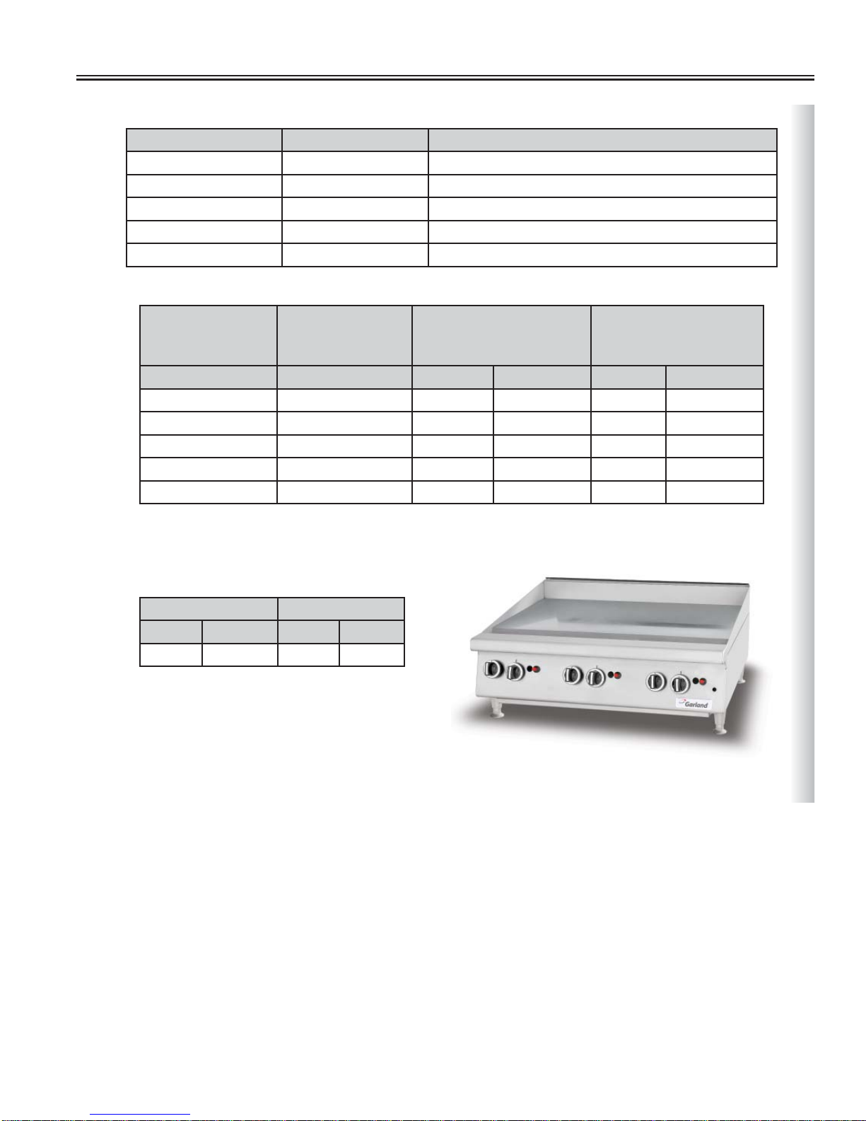
GTGG24-GT24M UTGG24-GT24M Gas, Thermostatically Controlled Griddle, 24” Wide
GTGG36-GT36M UTGG36-GT36M Gas, Thermostatically Controlled Griddle, 36” Wide
GTGG48-GT48M UTGG48-GT48M Gas, Thermostatically Controlled Griddle, 48” Wide
GTGG60-GT60M UTGG60-GT60M Gas, Thermostatically Controlled Griddle, 60” Wide
GTGG72-GT72M UTGG72-GT72M Gas, Thermostatically Controlled Griddle, 72” Wide
Line Ratings
Garland US Range Natural Gas @ 4.5”WC
Manifold Pressure
Models Models BTU/h Injectors# BTU/h Injectors#
GTGG24-GT24M UTGG24-GT24M 56,000 #33 56,000 #52
GTGG36-GT36M UTGG36-GT36M 84,000 #33 84,000 #52
GTGG48-GT48M UTGG48-GT48M 112,000 #33 112,000 #52
GTGG60-GT60M UTGG60-GT60M 140,000 #33 140,000 #52
GTGG72-GT72M UTGG72-GT72M 168,000 #33 168,000 #52
For use with Natural or Propane gas only.
Gas input ratings shown for installation up to 2000 ft (610m) above sea level.
L. Propane Gas @
10”WC Manifold
Thermostat Controlled Griddle Models (with Suffix M)
Pressure
Supply Operating Pressure
Natural Gas Propane Gas
“WC MBar “WC MBar
7 17.5 11 27.5
GTGG36-GT36M Shown
A_GC_SM_HDGASCOUNTERSERV_GT-UT-SERIES (Rev 1) Page 11
Page 12
Technical Data
Model Information
Garland Models US Range Models Model Information
GTBG24-NR24 UTBG24-NR24
GTBG36-NR36 UTBG36-NR36
GTBG48-NR48 UTBG48-NR48
GTBG60-NR60 UTBG60-NR60
Line Ratings
Gas Broiler, Non-Adjustable Grates and Cast Iron
Radiant
Gas Broiler, Non-Adjustable Grates and Cast Iron
Radiant
Gas Broiler, Non-Adjustable Grates and Cast Iron
Radiant
Gas Broiler, Non-Adjustable Grates and Cast Iron
Radiant
Garland US Range Natural Gas @ 4.5”WC
Manifold Pressure
Models Models BTU/h Injectors# BTU/h Injectors#
GTBG24-NR24 UTBG24-NR24 72,000 #45 72,000 #1.3mm
GTBG36-NR36 UTBG36-NR36 108,000 #45 108,000 #1.3mm
GTBG48-NR48 UTBG48-NR48 144,000 #45 144,000 #1.3mm
GTBG60-NR60 UTBG60-NR60 180,000 #45 180,000 #1.3mm
For use with Natural or Propane gas only.
Gas input ratings shown for installation up to 2000 ft (610m) above sea level.
Broiler Non-adjustable Grates Models
Supply Operating Pressure
Natural Gas Propane Gas
“WC MBar “WC MBar
7 17.5 11 27.5
L. Propane Gas @ 10”WC
Manifold Pressure
A_GC_SM_HDGASCOUNTERSERV_GT-UT-SERIES (Rev 1)Page 12
GTBG24-NR24 Shown
Page 13

Technical Data
Model Information
Garland Models US Range Models Model Information
GTBG24-AR24 UTBG24-AR24
GTBG36-AR36 UTBG36-AR36
GTBG48-AR48 UTBG48-AR48
GTBG60-AR60 UTBG60-AR60
Line Ratings
Garland US Range Natural Gas @ 4.5”WC
Models Models BTU/h Injectors# BTU/h Injectors#
GTBG24-AR24 UTBG24-AR24 72,000 #45 72,000 #1.3mm
GTBG36-AR36 UTBG36-AR36 108,000 #45 108,000 #1.3mm
GTBG48-AR48 UTBG48-AR48 144,000 #45 144,000 #1.3mm
GTBG60-AR60 UTBG60-AR60 180,000 #45 180,000 #1.3mm
For use with Natural or Propane gas only.
Gas input ratings shown for installation up to 2000 ft (610m) above sea level.
Gas, Broiler W/Adjustable Grates and Cast Iron
Radiant
Gas, Broiler W/Adjustable Grates and Cast Iron
Radiant
Gas, Broiler W/Adjustable Grates and Cast Iron
Radiant
Gas, Broiler W/Adjustable Grates and Cast Iron
Radiant
L. Propane Gas @ 10”WC
Manifold Pressure
Manifold Pressure
Broiler Adjustable Grates Models
Supply Operating Pressure
Natural Gas Propane Gas
“WC MBar “WC MBar
7 17.5 11 27.5
GTBG24-AR24 Shown
A_GC_SM_HDGASCOUNTERSERV_GT-UT-SERIES (Rev 1) Page 13
Page 14

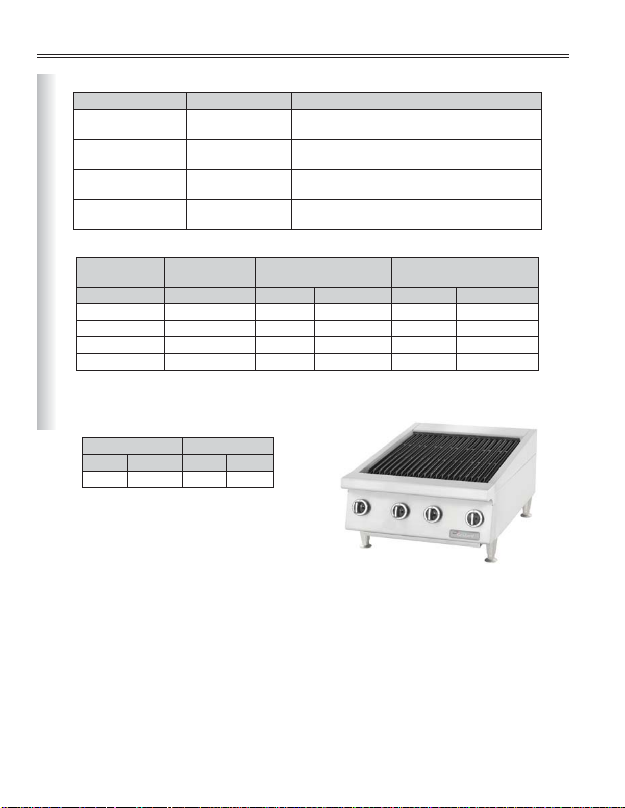
Technical Data
Model Information
Garland Models US Range Models Model Information
GTBG24-AB24 UTBG24-AB24
GTBG36-AB36 UTBG36-AB36
GTBG48-AB48 UTBG48-AB48
GTBG60-AB60 UTBG60-AB60
Line Ratings
Gas,Broiler W/Adjustable Grates and Ceramic
Coals, 24”Wide
Gas,Broiler W/Adjustable Grates and Ceramic
Coals, 36”Wide
Gas,Broiler W/Adjustable Grates and Ceramic
Coals, 48”Wide
Gas,Broiler W/Adjustable Grates and Ceramic
Coals, 60”Wide
Garland US Range Natural Gas @ 4.5”WC
Manifold Pressure
Models Models BTU/h Injectors# BTU/h Injectors#
GTBG24-AB24 UTBG24-AB24 60,000 #36 60,000 #51
GTBG36-AB36 UTBG36-AB36 90,000 #36 90,000 #51
GTBG48-AB48 UTBG48-AB48 120,000 #36 120,000 #51
GTBG60-AB60 UTBG60-AB60 150,000 #36 150,000 #51
For use with Natural or Propane gas only.
Gas input ratings shown for installation up to 2000 ft (610m) above sea level.
Supply Operating Pressure
Natural Gas Propane Gas
“WC MBar “WC MBar
7 17.5 11 27.5
L. Propane Gas @ 10”WC
Manifold Pressure
Broiler Adjustable Grates & Ceramic Coals Models
A_GC_SM_HDGASCOUNTERSERV_GT-UT-SERIES (Rev 1)Page 14
GTBG24-AB24 Shown
Page 15

General Pilot Procedures
Lighting Standing Pilots - All Models
After the appliance has been installed by a licensed
gas trades-person and all connections, pilot lights and
controls have been inspected for proper operation.
All gas appliances that use standing pilot systems are
generally assumed to be operating with the pilot on
continuously. The appliances should not be restarted
except in the event of a gas service interruption to the
facility.
If a pilot flame does go out, here are the basic steps to
check before you re-light the pilot:
1. Check that all gas lines are in place and secured
and there is no accumulation of gas inside the
unit.
2. Ensure the main shut off valve is in the off
position.
3. Turn off all individual burner valves.
4. Turn on or open the main shut off valve to the
appliance.
5. Follow the pilot lighting procedure applicable to
your model. The pilot should ignite within a few
attempts. You will be able to see the pilot flame on
a hotplate under the protective pilot shield cast
into the burner top grate. Pilot flames on griddles
and broilers can be viewed through observation
holes in the stainless steel front panels.
6. If you do not have a pilot flame established fairly
quickly and begin to smell gas, shut off the main
valve and wait five minutes to let the gas build-up
escape.
7. Only once the pilot flame has been established
should you turn on the burner control. When
the burner control is on it allows gas flow to the
burner. if there is no pilot flame it will allow gas
to build up and cause possible delayed ignition,
which could result in an explosion.
Open Top Burner Models
Pilots are easily accessible. Make sure the individual burner valve is
in the off position, then use an open flame device, match, or BBQ
lighter to ignite.
Broilers Models
Pilots are easily accessible. Make sure the individual burner valve is
in the off position, then use an open flame device, match, or BBQ
lighter to ignite.
Griddles with Valve Controls
• Make sure the individual valve control is in the off position.
• Use the piezo spark button(s), or electric spark if your model
has this option, to ignite the pilot.
• Once the pilots are lit you may now turn your valve control to
the high or low flame setting.
• To shut down the main burner turn the valve to off position.
A_GC_SM_HDGASCOUNTERSERV_GT-UT-SERIES (Rev 1) Page 15
Page 16

General Pilot Procedures (continued)
Griddles with SIT Thermostats
1. Turn thermostat control knob to the “ ” (Figure 1) position. Then push in to engage the
flow of gas through the safety device to the pilot.
2. While holding the knob in, light pilot by pressing the red piezo lighter button or the black
igniter button if your model has the electric ignition option.
3. Continue to hold the knob in for 15 seconds after ignition, then release. Pilot should remain
lit.
4. If the pilot burner fails to light or does not stay lit, wait 5 minutes and repeat steps 1 to 3.
5. Turn the thermostat knob to the desired cooking temperature.
Figure 1
6. To shut down the main burner, turn the control knob to the “
” position.
Griddles with GS Thermostats
1. Ensure the individual on-off valve is in the off position.
2. Use the piezo, or electric spark if your model has this option, button(s) to ignite the pilot.
3. Once the pilot is lit, turn the thermostat knob to the desired cooking temperature.
4. To shut down, turn individual on-off valves to the off position.
Shutdown Procedure
To shutdown, turn all main burner valves to OFF position. If the appliance is to be shut down for a extended period
of time, close the pilot valves, (gum valve) by turning their set screws fully clockwise.
Shutdown Procedure on Griddles with SIT Thermostats
The Garland/US Range SIT thermostat control knob is configured to leave the pilot flame on continuously. The
knob is designed with a tab which will not permit complete pilot shutdown. In order to shutdown the griddle pilot
flame completely, you must perform Steps 1 to 3 below. Note There are no pilot valves (gum valve).
A
B
C
1. Turn griddle thermostat control knob to symbol “ ” position and then
loosen the knob set screw (C). Gently pull knob off.
2. With the knob removed, push-down and turn the hub until the symbol (
lines up with symbol (A). With the hub in the position shown, the gas should
be off at the pilots and burners. There are no pilot valves (gum valve).
Hub
Pilot Flame On
3. Finally, turn the manual valve on the main gas supply to the OFF position.
A_GC_SM_HDGASCOUNTERSERV_GT-UT-SERIES (Rev 1)Page 16
•) (B)
Complete Shutdown
Page 17

Gas Pressure Regulator
Rear Gas Pressure Regulator Connection Options
• Pipe size: 3/4” (19.05mm) NPT for all models.
Ther are two options to connent a Gas Pressure Regulator, as shown in Figure 2 and Figure 3 below. Refer to
Installation and Operation Manual for further details
Figure 2:
Gas pressure regulator connection is designed to
flush-mount.
Note: when installing as a flush mount gas pressure
regulator connection, (to allow for equipment
installation against a noncombustible wall), a
certified flexible gas hose and quick disconnect
assembly is required to allow the unit to be moved in
the event an adjustment of the gas pressure regulator
is required.
Figure 2
Figure 3:
Gas pressure regulator connection is designed
straight through.
Garland recommends the use of certified flexible gas
hose and quick disconnect assembly to allow the unit
to be moved in the event an adjustment of the gas
pressure regulator is required.
Purpose of gas pressure regulator
Basics Of A Gas Pressure Regulator
Removable Seal Cap
Atmospheric
Vent
Inlet
Adjustment (Screw)
Loading Element
(Spring)
Measuring Element
(Diaphragm)
Restricting Element
(Valve Disk and Seat)
Outlet
Figure 3
Gas pressure regulators have two main purposes, to
reduce supply main pressure to safe operating pressures
of connected appliances and to maintain constant
downstream pressure, regardless of changes in the gas
flow or upstream pressure variations.
Note: Gas service suppliers usually supply gas pressure
higher than the safe operating pressures of connected
appliances.
If an appliance receives too much fuel, it will over-fire. If
it receives too little fuel, it will under-fire. It will produce
too much or too little heat. Combustion characteristics
could change resulting in carbon monoxide generation.
The appliance may not work properly or efficiently.
Note: Always refer to the rating plate of appliance for actual manifold pressure required.
A_GC_SM_HDGASCOUNTERSERV_GT-UT-SERIES (Rev 1) Page 17
Page 18

Open Top Burners Adjustments
Pilot Adjustment Valves
• Also known as gum valves (Figure 16).
• Available in single or double.
• Adjustable with a set-screw using a straight blade pocket
screwdriver.
• Turn set-screw counter-clockwise to increase flow; turn
set-screw clockwise to decrease flow.
• Precisely adjust the pilot flame to a slight yellow tip to
provide maximum performance.
Pilot Adjustment Valves Location
• All pilots adjustment valves are located on the manifold,
behind the front panel (Figure 17).
• To remove the front panel, first remove the knobs with set
screws. Then release the four (4) screws holding the panel
and remove panel.
Burner Gas / Air Shutter Adjustment
Adjustable
Set-Screw
Pilot Tip Figure 16
Front
Panel
Gas
Manifold
Gum
Val ve
Figure 17
Variations in field conditions, and/or rough handling of the
equipment in transit may result in the need for adjustment of
the primary air to the burners. The following steps will show
you how to provide a sharp blue flame at the full rate (open
valve fully for the maximum gas flow).
1. On the burner locate the aeration shutter (Figure 6).
2. Loosen the fixing screw so that the aeration shutter turns
freely.
3. Turn on the gas flow and ignite the burner.
4. Rotate the air shutter to obtain the 1/2” stable, sharp inner
blue cones (Figure 7).
US Range and Garland Burner Heads:
Fixing Screw
Air Flow
Injector LŽĐĂƟŽŶ
AeraƟon
^ŚƵƩĞƌ
Figure 6
1/2” stable sharp inner blue cone
Open Burner
Figure 7
US Range
Burner Head
Garland
Star Burner Head
A_GC_SM_HDGASCOUNTERSERV_GT-UT-SERIES (Rev 1)Page 18
Page 19

Troubleshooting — Open Top Burners
WARNING
Inspection, testing and repair of equipment should be performed only by qualified service personnel. Certain
procedures in this section require gas tests or measurements while gas is applied to the unit. Use extreme caution
at all times. If test points are not easily accessible, disconnect main gas line, attach test equipment and reapply gas
supply to continue the test.
Always confirm manifold gas pressure at all times.
PROBLEM POSSIBLE CAUSE SOLUTION
Burner Flame soft –lazy tip yellow Not enough air mixing with gas Open air shutter
Flames lift off burners
Too much air mixing with gas Reduce air shutter openingFlashes back in burner
“Pop’s” excessively when turned off
Unit over-gassed fired Adjust manifold pressure
Delayed ignition
Pilot burner will not ignite
Flame lifts off pilot Pilot over-gassed fired Adjust pilot valve
Incorrect injector Check injector size
Burner ports plugged Clean burner ports
Pilot flame too small Adjust pilot valve
Draft in Kitchen Determine cause
A_GC_SM_HDGASCOUNTERSERV_GT-UT-SERIES (Rev 1) Page 19
Page 20

Griddle Adjustments
Griddle Spark Igniter
Garland has two different igniter systems on the griddle units:
1. Push-button piezo igniter system
2. Electronic Spark igniter system
1. Push-button Piezo igniter system (Figure 8) consists
of a small, spring-loaded hammer, which creates
voltage when a button is pressed. 120V electric
connection is NOT required; wires are needed to move
the electricity to an electrode close to the pilot. Proper
alignment is critical for better performance. Only one
spark is generated per press of the button. When
equipment installed above 8000 feet sea-level, lighters
with piezo-electric ignition are no longer reliable.
2. Electronic Spark Igniter System consists of an
Electronic Spark Generator (ESG) box (Figure 10),
a momentary switch (Figure 9), and electrical
components, plus wires to discharge a spark across a
gap between electrodes (spark gap). See below, section
2.3 ESG Technical Specification.
Figure 8
Momentary
Switch Side Panel
Front
Rail
When electrical voltage connection is required, refer to
section Wiring Diagram.
2.1 Remove, Test, and Replace a Momentary Switch
(MS)
a. Ensure power cord is unplugged.
b. Remove decorative dress nut off the
momentary switch
c. Remove knobs with set screws.
d. Remove the four (4) screws from front panel
and remove panel.
e. Griddle with SIT Thermostat: On the LEFT
hand side of the unit remove screw and the
momentary switch side panel (Figure 9).
Griddle with GS Thermostat: On the
RIGHT hand side of the unit remove screw
and the momentary switch side panel
(not shown).
f. Remove momentary switch nut and unplug
rear terminal wires.
Momentary
Electronic Spark
Generator (ESG)
Switch
Figure 9. SIT Tstat and Momentary Switch
REAR VIEW
ZĂƟŶŐ^ĞƌŝĂů
Plate
Figure 10
Knob
g. Connect multi-tester probes on the
momentary switch terminals. Continuity
must be indicated when button is pressed,
if not, replace switch.
A_GC_SM_HDGASCOUNTERSERV_GT-UT-SERIES (Rev 1)Page 20
Page 21

Griddle Adjustments (continued)
2.2 Removal and Replacement of Electronic Spark
Generator (ESG);
a. Verify the rating plate voltage to ESG specification.
See section 2.3 below.
b. Ensure power cord is unplugged.
c. Before removing ESG, check wires for continuity
in case a wire is damaged. Refer to section Wiring
diagrams.
d. Remove the ESG front box panel located at the back
of the unit (Figure 10).
e. Unscrew the two screws at each side of the ESG
unit, and unplug the terminal wires. Remove the
ESG unit.
f. Replace ESG unit in reverse order.
2.3 ESG Technical Specification
Input Voltage (1-2) 220-240 +10%,-15% (1-2) 110-120 ±10%
Spark Type Repetitive, 3Hz at 230v Repetitive, 3Hz at 120v
Outlets (a-d) 4 (a-d) 4
Main Frequency 50-60 Hz 50-60 Hz
Electronic Spark Generator (ESG)
Power Consumption 0.8VA MAX. 0.6VA MAX.
Spark Gap 4 X 4 mm (0.157”) MAX. 4 X 4 mm (0.157”) MAX.
REAR VIEW
Electronic Spark
Generator (ESG)
ZĂƟŶŐ^ĞƌŝĂů
Plate
Part # 4514749 Part # 4514750
Figure 10
High Tension Lead (HTL) & Insulation
The pilot HTL is exposed to high temperatures where they are located.
IMPORTANT
Keep the insulation in place.
Insulation should cover wire, connector, plus bottom of electrode as
shown in Figure 11.
Electrode
Wire Insulation
(black)
Wire (HTL)
(orange)
Figure 11.
A_GC_SM_HDGASCOUNTERSERV_GT-UT-SERIES (Rev 1) Page 21
Page 22

Griddle Adjustments — SIT Thermostat
Thermostatic Griddle Adjustments (SIT Control)
SIT Valve Control
Garland’s Heavy Duty Counterline contains a gas control system enclosed in one component — the SIT Control.
The griddle pilot safety system is an internal subcomponent of the control. This control (part#CK4528339) is
modified to snap action. There is no Bypass on this control.
This control, although very similar to the mechanical controls found on Garland’s current range and griddle
models, has several major economical efficiencies that offer reliability advantages to the customer.
NOTE
0
1. Griddle SIT control - Temperature control range 175
2740C).
2. It is a safety valve, and thermostat in one assembly. The safety valve
should not be removed from the body of the control for any reason.
3. Verify manifold pressure before replacing.
4. Familiar Open circuit, closed circuit, and drop out checks should be
made if the internal safety valve is suspected to be at fault.
F - 5250F (800C -
5. This control does not require any initial flame setting.
6. This control does not require internal calibration. (Some minor knob
adjustments could be appropriate, but it would be rare.
7. If a SIT control component is suspected to be internally at fault,
replace the control.
Installing a Thermocouple
A thermocouple nut should be started and turned all the way in by hand. An additional quarter turn with a small
wrench will be sufficient to seat the lock washer and maintain adequate contact. Connection that is too loose or
too tight of the thermocouple nut to the automatic pilot valve can prevent the thermocouple from activating the
valve. Inspect the thermocouple lead visually to ensure there are no cracks or ruptures.
Testing the Magnet Assembly and Thermocouple Operation
Heating at the thermocouple tip by a pilot flame produces an electric potential for energizing the magnet that, in
turn, holds open the main and pilot valves.
When the pilot is “out” or improperly adjusted, insufficient heat is applied to the thermocouple tip to produce
adequate electrical generation that results in the control shutting itself off. If, while following the proper lighting
procedures, the magnet cannot be made to “hold”, inspect the pilot flame for proper size and adjustment (see pilot
burner adjustment).
If the magnet will still not hold, perform the following tests: closed circuit test, open circuit test.
A_GC_SM_HDGASCOUNTERSERV_GT-UT-SERIES (Rev 1)Page 22
Page 23

Griddle Adjustments — SIT Thermostat (continued)
Closed Circuit Test (To test magnet & thermostat as a complete unit)
To perform the closed circuit test, remove the thermocouple lead from
Ter minal Boss
RED
Adapter
the magnet contact.
Place an adapter in the magnet contact and turn the thermocouple
into the adapter finger tight. Connect millivolt leads to the adapter
and thermocouple lead as shown.
Thermocouple Tube
In the Sit Control, insert a metric M9 adapter in the magnet
contact to complete the safety valve check as shown
BLACK
PN 4526299
1. Make sure the thermocouple is properly inserted into the pilot housing, and has no play. Also check gas
tubing connection at the pilot and tighten if loose.
2. Re-light the pilot, and read the meter after the pilot has been burning for three minutes. If the pilot will not
continue burning, depress and hold the temperature knob to manually open the SIT safety valve to check
the thermocouple output for this closed circuit check. If insufficient (normal output for closed circuit is 8-14
millivolts), and under 7 millivolts, replace the thermocouple. If the millivolt reading is above 7 mV, and the
safety magnet does not hold, replace the valve.
3. If the closed circuit mV reading is the same as the open circuit reading, the coil is electrically open, and the
valve must be replaced.
4. Check for drop out time which should occur within 60 seconds and at approximately 2 mV since the pilot was
out.
5. Re-light the pilot and turn on the main burner. As the griddle heats up, it is normal to see a slight decrease in
millivolts.
Open Circuit Test
1. Disconnect the thermocouple from the safety valve.
2. Attach the thermocouple to the millivolt test instrument.
3. Heat the sensor end of the thermocouple at the pilot flame or similar flame characteristics, monitoring the
millivolt meter
4. If the millivolt reading is below 18 millivolts, replace the thermocouple
Note: The SIT thermocouple open circuit voltage will be approximately 18-28 millivolts
SIT Thermocouple
Closed Circuit 8-14
mV
Open Circuit 18-28
Drop Out 2
A_GC_SM_HDGASCOUNTERSERV_GT-UT-SERIES (Rev 1) Page 23
Page 24

Griddle Adjustments — SIT Thermostat (continued)
Thermostatic Griddle Pilot Adjustment
1. Adjustment with a screw located on the SIT control (refer to photo).
2. Turn the screw clockwise to reduce the gas flow.
3. Precisely adjust the pilot flame to a slight yellow tip to provide maximum performance. Flame must engulf
only the tip of thermocouple.
No adjustment here
Pilot adjustment screw. The
pilot ame should be approximately
3/4” long
A_GC_SM_HDGASCOUNTERSERV_GT-UT-SERIES (Rev 1)Page 24
3/4" long
Engulf Tip of thermocouple
Page 25

Griddle Adjustments — SIT Thermostat (continued)
SIT Valve Calibration Instructions
These are mandatory steps for thermostat validation in the field. You MUST perform these steps before replacing.
They confirm if the SIT griddle control is working as per specification or is failing.
Note:
• Griddle plate must be clear (without product).
• Ensure your temperature meter is accurate (surface probe or magnetic T-couple only).
• Calibration temperature = average of the flame ON and flame OFF/ temperature, (on+off )/2.
1 Check Manifold Pressure 4.5”W.C. Natural Gas; 10” W.C. Propane Gas
Inspect pilots and place
2
thermocouple on plate (as
shown figure 13)
36"(914.4mm)
'ƌŝĚĚůĞ^ĞĐƟŽŶ
Moisten the thermocouple with oil.
12" (304.8mm)
6" (152.4mm)
Place
Probe
Here
FRONT
Figure 13. Griddle Top View - Data for Griddle with SIT thermostat. Figure 14.
3 Set Dial at 3500F on all burners
4 Start Up
6"(152.4mm)
Screws for Knob Dial
(Û)URP0LGSRLQW
Take dial to Max. and back down to 3500F position on the dial
insert.
Do not take temperature readings for the first 30 minutes if the
griddle was started from cold. Must be preheated and saturated.
5 Visual check Pilot flame and ignition, burner flame.
0
Note: Accepted Tolerance Temperatures swing at 350
Average temperatures at 350
F is ± 150F
0
F ± 100F
Read and record consecutively the lowest and highest
temperature values for each control (approx. 15 minutes).
0
6 Monitor Temperature
Temperature must be within 350
F ± 250F.
The average of high and low values must be 3500F ± 100F.
If not, go to step 7.
Additional Calibration if not
7
within accepted tolerance
(Figure 14).
0
Set Dial at 400
8
and confirm calibration on
F on all burners
Rotate the dial in small increments until within tolerance and
adjust dial following “Knob calibration instructions” . Knob
calibration can adjust set point by 30
setting).
Take dial to Max. and back down to 4000F position on the dial
insert. The average of high and low values must be 4000F ± 200F.
those corrected at step 7
Change the control if low and high values exceed swing of 50
9 Replacement
and/or average is not between 3800F and 4200F after Knob
Calibration Procedure.
Calibration
0
F (± 150F from midpoint
0
F
A_GC_SM_HDGASCOUNTERSERV_GT-UT-SERIES (Rev 1) Page 25
Page 26

Griddle Adjustments — GS Thermostat
Thermostatic Griddle Adjustments (GS Control)
GS Thermostat Calibration Instructions
1. Use a test instrument with a special disc type thermocouple or a reliable surface type pyrometer.
Note A drop of oil on the face of the disc will provide better contact with the griddle plate.
2. Set all griddle thermostats to 350 deg F. In order to stablize the griddle temperature, you must cycle the
thermostats twice before taking a test reading.
3. Check the griddle temperature when the thermostat just cycles OFF by placing the thermocouple firmly on
the griddle surface directly above the sensing bulb of the thermostat.
35-7/16"(900mm)
'ƌŝĚĚůĞ^ĞĐƟŽŶ
Place
Probe
Here
5-3/4" (146.1mm)
11-13/16" (300mm)
18-3/4"(476.3mm)
FRONT
4. Take the reading and it should be between 335 deg F and 365 deg F. If the reading is outside of these limits,
calibrate as follows:
a. Carefully remove the dial without disturbing the
shaft position.
b. Hold the shaft steady and with a small flat screw
driver, turn the calibration screw located inside
the shaft clockwise to descrease temperature or
anit-clockwise to increase temperature.
Note: Each 1/4 turn of the screw will create a
change of approximately 25 deg F.
c. Replace the thermostat dial and repeat steps 1
through 3 to verify that a correct adjustment has
been made.
A_GC_SM_HDGASCOUNTERSERV_GT-UT-SERIES (Rev 1)Page 26
Page 27

Griddle Adjustments — GS Thermostat (continued)
Replace a GS Thermostat
Note: It is not required to raise the griddle assembly for thermostat replacement.
1. Remove knobs from all valves and thermostats.
2. Un-install screws retaining the valve panel to unit and remove valve panel from unit.
3. Disconnect tubing connecting thermostat to on-off valve and to burner orifice fitting.
4. While grasping capillary line as close as possible to front edge of griddle plate, slide back the insulation
sleeve.
5. Carefully pull outward on capillary and slide thermostat bulb out of clamp assembly on bottom of plate.
6. Remove the insulation sleeve from capillary.
7. Unfasten screws mounting thermostat to manifold and remove thermostat from unit.
8. Mount replacement thermostat to manifold with screws removed in Step 7.
9. Slide insulation sleeve removed in Step 6 onto capillary of new thermostat.
10. Place thermostat bulb through cut-out in front support/shield and into the V-opening of clamp assembly
and push into clamp assembly until it comes to a stop.
11. Slide insulation sleeve along capillary line up to start of clamp assembly.
12. Re-install valve panel and knobs.
A_GC_SM_HDGASCOUNTERSERV_GT-UT-SERIES (Rev 1) Page 27
Page 28

Griddle Adjustments — Hi/Low Valve
Griddles with Hi/Low Valves
The Hi/Low Gas Valves are located behind the knobs, connected to the manifold. Use a straight blade pocket
screwdriver to adjust low setting higher or lower.
Reminder
. Adjustments on valves are for the low flames setting only. See section “Adjuct Hi-Lo Valve”
below.
Adjust a Hi-Lo Valve
Griddles equipped with Hi-Lo valves required a low flame setting. To
adjust:
1. Burner must be cold.
2. Ensure pilot flames are lit and adjusted.
3. Turn dial to “LO” position, then remove dial.
4. With a screwdriver, turn the small adjusting screw inside the valve
stem and adjust to obtain the low cooking temperature desired,
maintaining a stable flame covering the entire burner (minimum
3/16” (5mm) long flame).
5. Replace the dial and turn to “OFF” position.
Remove and replace a Hi/Low Valve
1. Remove knobs.
2. Remove the four (4) screws from front panel and remove panel.
Adjustable Valve
3. Disconnect gas line and then unscrew valve from manifold.
4. Install new valve in reverse order.
5. Reconnect gas line.
6. Check for gas leaks.
Burner Gas / Air Shutter Adjustment
Variations in field conditions, and/or rough handling
of the equipment in transit may result in the need
for adjustment of the primary air to the burners. The
following steps will show you how to provide a sharp
blue flame at the full rate (open valve fully for the
maximum gas flow).
1. On the burner locate the aeration shutter (figure 6).
2. Loosen the fixing screw so that the aeration shutter
turns freely.
3. Turn on the gas flow and ignite the burner.
4. Rotate the air shutter to obtain the 5/16” stable,
sharp inner blue cones (figure 15).
Fixing Screw
Air Flow
5/16” stable sharp inner blue cone
H Burner - Side View
Injector LŽĐĂƟŽŶ
AeraƟon
^ŚƵƩĞƌ
Figure 6
Figure 15
A_GC_SM_HDGASCOUNTERSERV_GT-UT-SERIES (Rev 1)Page 28
Page 29

Troubleshooting — Griddles
WARNING
Inspection, testing and repair of equipment should be performed only by qualified service personnel. Certain
procedures in this section require gas tests or measurements while gas is applied to the unit. Use extreme caution
at all times. If test points are not easily accessible, disconnect main gas line, attach test equipment and reapply gas
supply to continue the test.
Always confirm manifold gas pressure at all times.
PROBLEM POSSIBLE CAUSE SOLUTION
Burner Flame soft –lazy tip yellow Not enough air mixing with gas Open air shutter
Flames lift off burners
Too much air mixing with gas Reduce air shutter openingFlashes back in burner
“Pop’s” excessively when turned off
Thermostat out of Calibration
(Thermostat Griddle)
Griddle too hot or too cold
Hi/lo valve set wrong
(Hi/Lo Valve Griddle)
Unit over-gassed fired Adjust manifold pressure
Delayed ignition
Pilot burner will not ignite
Flame lifts off pilot Pilot over-gassed fired Adjust pilot valve
Pilot Outage (SIT Control Models) Bad thermocouple
Incorrect injector Check injector size
Burner ports plugged Clean burner ports
Pilot flame too small Adjust pilot valve on manifold
Draft in Kitchen Determine cause
Check Calibration temperature
with actual readings. See
calibration procedure.
Adjust hi/lo valve. Adjust on
low setting only, burner cold.
Lowest stable flame
Check actual mV open and
closed circuits. See table
below.
SIT Thermocouple
Closed Circuit 8-14
mV
Open Circuit 18-28
Drop Out 2
A_GC_SM_HDGASCOUNTERSERV_GT-UT-SERIES (Rev 1) Page 29
Page 30

Broiler Adjustments
Pilot Adjustment Valves
• Also known as gum valves (Figure 16).
• Available in single or double.
• Adjustable with a set-screw using a straight blade pocket
screwdriver.
• Turn set-screw counter-clockwise to increase flow; turn setscrew clockwise to decrease flow.
• Precisely adjust the pilot flame to a slight yellow tip to provide
maximum performance.
Pilot Adjustment Valves Location
• All pilots adjustment valves are located on the manifold,
behind the front panel (Figure 17).
• To remove the front panel, remove knobs with set screws.
Then release the four (4) screws holding the panel and remove
panel.
Gas Burner Control Valves
1. Non-adjustable Burner Control Valve (Charcoal models
only)
Adjustable
Set-Screw
Pilot Tip Figure 16
Front
Panel
Gas
Manifold
Gum
Val ve
Figure 17
• Regulates the flow of gas to the burner.
• Fixed and non-adjustable control.
• Valves located behind the knobs, connected to the
manifold.
2. Adjustable Hi/Low Burner Control Valve
• Regulates the flow of gas to the burner.
• Use a straight blade pocket screwdriver to adjust low
setting higher or lower.
• Valves are located behind the knobs, connected to the
manifold.
• Reminder: Adjustments on valves are for the low
flames setting only.
To remove and replace a control valve:
1. Remove the knobs.
2. Remove the four (4) screws holding the front panel, and remove panel.
Non-adjustable Valve
Adjustable Valve
3. Disconnect gas line. Then unscrew valve from the manifold.
4. Install a new valve in reverse order.
5. Reconnect gas line.
A_GC_SM_HDGASCOUNTERSERV_GT-UT-SERIES (Rev 1)Page 30
Page 31

Broiler Adjustments (continued)
Burner Gas / Air Shutter Adjustment
Variations in field conditions, and/or rough handling of the equipment in transit may result in the need for
adjustment of the primary air to the burners. Follow the steps below to provide a sharp blue flame at the full rate
(open valve fully for the maximum gas flow).
To adjust a burner air shutter:
1. Confirm manifold pressure matches rating
plate.
2. Locate the aeration shutter on the burner.
• For Charcoal Broiler Models,
see Figure 6.
• For Radiant Broiler Models,
see Figure 18.
3. Loosen the fixing screw to allow the
aeration shutter turn freely.
4. Turn on the gas flow and ignite the burner.
5. Rotate the air shutter until you obtain
flame with 5/16” stable, sharp inner blue
cones (Figure 15).
6. Tighten the fixing screw.
ĞƌĂƟŽŶ^ŚƵƩůĞƌ
Fixing Screw
Air Flow
Figure 6. Charcoal Broiler Air Shutter.
Fixing Screw
Air Flow
Broiler Straight Burner
Figure 18. Radiant Broiler Air Shutter.
5/16” stable sharp inner blue cone
Injector LŽĐĂƟŽŶ
AeraƟon
^ŚƵƩĞƌ
H Burner - Side View
Figure 15. H Burner shown as an example.
A_GC_SM_HDGASCOUNTERSERV_GT-UT-SERIES (Rev 1) Page 31
Page 32

Troubleshooting — Broilers
WARNING
Inspection, testing and repair of equipment should be performed only by qualified service personnel. Certain
procedures in this section require gas tests or measurements while gas is applied to the unit. Use extreme caution
at all times. If test points are not easily accessible, disconnect main gas line, attach test equipment and reapply gas
supply to continue the test.
Always confirm manifold gas pressure at all times.
PROBLEM POSSIBLE CAUSE SOLUTION
Burner Flame soft –lazy tip yellow Not enough air mixing with gas Open air shutter
Flames lift off burners
Flashes back in burner
“Pop’s” excessively when turned off
Delayed ignition
Pilot burner will not ignite
Flame lifts off pilot Pilot over-gassed fired Adjust pilot valve
Griddle too hot or too cold
Too much air mixing with gas Reduce air shutter opening
Unit over-gassed fired Adjust manifold pressure
Incorrect injector Check injector size
Burner ports plugged Clean burner ports
Pilot flame too small Adjust pilot valve
Draft in Kitchen Determine cause
Hi/Lo valve set wrong (Broiler, Hi/
Lo Valves Models)
Adjust hi/lo valve. Adjust on
low setting only, burner cold.
Lowest stable flame
A_GC_SM_HDGASCOUNTERSERV_GT-UT-SERIES (Rev 1)Page 32
Page 33

Notes
A_GC_SM_HDGASCOUNTERSERV_GT-UT-SERIES (Rev 1) Page 33
Page 34

Wiring Diagram (GTGG/UTGG__M Models Electric Spark)
A_GC_SM_HDGASCOUNTERSERV_GT-UT-SERIES (Rev 1)Page 34
Page 35

Wiring Diagram (GTGG/UTGG Electric Spark)
<9*;4.5.,=;8-.<
MODELS 60" & 72" WIDE REQUIRE (2) SPARK GENERATORS
MODELS 24", 36" & 48" WIDE REQUIRE (1) SPARK GENERATOR
0;8>7->7><.-
=.;627*5<
2072=287@2;.<
0;8>7->7><.-
=.;627*5<
<9*;4
0.7.;*=8;
<9*;4
0.7.;*=8;
0*=.@
5
5
7.
*
5
7.
+540;7;.-
/.6*5.<=;29!
!,
*
*
*
!,
5
07-
FLEX CONDUIT 38" (FOR 24" & 48" WIDTH MODELS)
FLEX CONDUIT 50" (FOR 36", 60" & 72" WIDTH MODELS)
<@2=,1+8A
75
<,1.6*=2,-2*0;*6
686.7=*;B<@2=,1
,866.;,2*5;*70.<5262=.-
62<<2<<*>0*87=*;28,*7*-*
.07- 7 5
+5*,45
@12=.7
?875B
0;..707-
0=0>=0.5.,=;2,<9*;4
"
57,-4
A_GC_SM_HDGASCOUNTERSERV_GT-UT-SERIES (Rev 1) Page 35
,?/
Page 36

Gas Conversion Kits (from Natural to Propane)
PART # KIT COMPONENTS BTU/HR PER BURNER QTY
Open Tops and Step-Up Open Tops (Kit part# 4528882)
M853 #53 Ori ce – Open Top Burners (Hotplate Only) – Pro
M81.6MM 1.6Mm Ori ce – Open Top Burners (Step Up Only) – Pro
4528897 Instructions Conversion Kit Hd Hotplate – Nat/Propane
4528891 Label – Conversion Ratings Hd Hotplates
4516405 Label - Conversion Declaration
2127500 3/4" Regulator Propane 10" W.C.
Hi/Low Griddle model GTGG__-G__ (Kit Part# 4528884)
M853 #53 Ori ce – Griddles (Hi-Lo Valve) – Pro 26,000 6
2200703 Pilot Ori ce #23 Propane 6
4528898 Instructions Conversion Kit Hd Counter Griddles – Nat/Propane 1
4528893 Label – Conversion Ratings Hd Counter Griddles 1
4516405 Label - Conversion Declaration 1
2127500 3/4" Regulator Propane 10" W.C. 1
Hi/Low Griddle model GTGG__-G__M (Kit Part# 4531366)
M853 #53 Ori ce – Griddles (Hi-Lo Valve) – Pro 27,000 6
2200703 Pilot Ori ce #23 Propane 6
4531371
4516405 Label - Conversion Declaration 1
4531369
2127500
Instructions Conversion Kit GTGGM Griddle, Nat/Propane 1
Label - Conversion Ratings, Propane 1
3/4” Regulator Propane 10” W.C. 1
26,000 8
27,000 8
1
1
1
1
Thermostatic Griddle model GTGG__-GT__ (Kit Part# 4528886)
M851 #51 Ori ce – Griddles (Tstat) – Pro 32,000 6
2200703 Pilot Ori ce #23 Propane
4528898 Instructions Conversion Kit Hd Counter Griddles – Nat/Propane 1
4528893 Label – Conversion Ratings Hd Counter Griddles 1
4516405 Label - Conversion Declaration 1
2127500 3/4" Regulator Propane 10" W.C. 1
Thermostatic Griddle model GTGG__-GT__M (Kit Part# 4531368)
M852 #52 Ori ce – Griddles (Tstat) – Pro 28,000 6
2200703 Pilot Ori ce #23 Propane
4531371 Instructions Conversion Kit GTGGM Griddle, Nat/Propane
4516405 Label - Conversion Declaration 1
4531369 Label - Conversion Ratings, Propane
2127500 3/4” Regulator Propane 10” W.C.
Fixed & Adjustable Radiant Broiler (Kit Part# 4528888)
M81.3MM 1.3Mm Ori ce – Radiant Broiler – Pro 18,000 10
4528899 Instructions Conversion Kit Hd Counter Broilers – Nat/Propane 1
4528895 Label – Conversion Ratings Hd Counter Broilers 1
4516405 Label - Conversion Declaration 1
2127500 3/4" Regulator Propane 10" W.C. 1
Adjustable Charcoal Broiler (Kit Part# 4528890)
M851 #51 Ori ce – Ceramic Briquette Broiler Pro 30,000 6
4528899 Instructions Conversion Kit Hd Counter Broilers – Nat/Propane 1
4528895 Label – Conversion Ratings Hd Counter Broilers 1
4516405 Label - Conversion Declaration 1
2127500 3/4" Regulator Propane 10" W.C. 1
6
6
1
1
1
A_GC_SM_HDGASCOUNTERSERV_GT-UT-SERIES (Rev 1)Page 36
Page 37

Gas Conversion Kits (from Propane to Natural)
PART # KIT COMPONENTS BTU/HR PER BURNER QTY
Open Tops and Step-Up Open Tops (Kit part# 4528881)
M836 #36 Ori ce - Open Top Burners (All Models) - Nat 30,000 8
4528897 Instructions Conversion Kit Hd Hotplate – Nat/Propane 1
4528892 Label – Conversion Ratings Hd Hotplates 1
4516405 Label - Conversion Declaration 1
2127502 3/4" Regulator Natural 4½" W.C. 1
Hi/Low Griddle model GTGG__-G__ (Kit Part# 4528883)
M837 #37 Ori ce – Griddles (Hi-Lo Valve) - Nat 26,000 6
2200702 Pilot Ori ce #32 Natural
4528898 Instructions Conversion Kit Hd Counter Griddles – Nat/Propane 1
4528894 Label – Conversion Ratings Hd Counter Griddles 1
4516405 Label - Conversion Declaration 1
2127502 3/4" Regulator Natural 4½" W.C. 1
Hi/Low Griddle model GTGG__-G__M (Kit Part# 4531365)
M837 #37 Ori ce – Griddles (Hi-Lo Valve) - Nat 27,000 6
2200702 Pilot Ori ce #32 Natural
4531371 Instructions Conversion Kit GTGGM Griddle, Nat/Propane 1
4516405 Label - Conversion Declaration 1
4531370 Label - Conversion Ratings, Natural 1
2127502 3/4” Regulator Natural 4½” W.C. 1
6
6
Thermostatic Griddle model GTGG__-GT__ (Kit Part# 4528885)
M836 #36 Ori ce – Griddles (Tstat) – Nat 32,000 6
2200702 Pilot Ori ce #32 Natural
4528898 Instructions Conversion Kit Hd Counter Griddles – Nat/Propane 1
4528894 Label – Conversion Ratings Hd Counter Griddles 1
4516405 Label - Conversion Declaration 1
2127502 3/4" Regulator Natural 4½" W.C. 1
Thermostatic Griddle model GTGG__-GT__M (Kit Part# 4531367)
M833 #33 Ori ce – Griddles (Tstat) – Nat 28,000 6
2200702 Pilot Ori ce #32 Natural
4531371 Instructions Conversion Kit GTGGM Griddle, Nat/Propane
4516405 Label - Conversion Declaration 1
4531370 Label - Conversion Ratings, Natural 1
2127502 3/4” Regulator Natural 4½” W.C. 1
Fixed & Adjustable Radiant Broiler (Kit Part# 4528887)
M845 #45 Ori ce – Radiant Broiler - Nat 18,000 10
4528899 Instructions Conversion Kit Hd Counter Broilers – Nat/Propane 1
4528896 Label – Conversion Ratings Hd Counter Broilers 1
4516405 Label - Conversion Declaration 1
2127502 3/4" Regulator Natural 4½" W.C. 1
Adjustable Charcoal Broiler (Kit Part# 4528889)
M836 #36 Ori ce – Ceramic Briquette Broiler Nat 30,000 6
4528899 Instructions Conversion Kit Hd Counter Broilers – Nat/Propane 1
4528896 Label – Conversion Ratings Hd Counter Broilers 1
4516405 Label - Conversion Declaration 1
2127502 3/4" Regulator Natural 4½" W.C. 1
6
6
1
A_GC_SM_HDGASCOUNTERSERV_GT-UT-SERIES (Rev 1) Page 37
Page 38

Bulletins & Revision History
Bulletins
BULLETIN # SUBJECT DATE
03B2010SP New Heavy Duty Gas Counter line 20JULY10
07B2010S Wire Link Rod Upgrade 26OCT10
GAR0111AIC Wire Link Rod & Lifting Bar Assembly Lock Upgrades 4FEB11
GAR0211AIC Correct Gas Connections for SIT Griddle Controls 25MAR11
GAR0511AIC Service Kit for Momentary Switch Part Numbers 4527834 & G03053-1 13SEP11
GAR0711AIC New SIT Griddle Control Thermostat Kit 30SEP11
Revision History
REV# DESCRIPTION DATE
0 New Service Manual released 20AUG10
1 Added new GT/UTGG__M models with GS Tstat. 18MAR13
A_GC_SM_HDGASCOUNTERSERV_GT-UT-SERIES (Rev 1)Page 38
Page 39

Page 40

GT/UT Series Heavy Duty Counter Equipment — Service Manual
Garland Commercial Ranges, Ltd.
1177 Kamato Road
Mississauga, Ontario L4W 1X4 Canada
General Inquiries P: 905 624 0260 F: 905 624 5669
www.Garland-Group.com
Parts & Service
1 800 427 6668 (Phone, US & Canada)
1 800 361 7745 (Fax, US & Canada)
 Loading...