

Page 1

UnderCounter Ice Machines
UG Series
Installation, Operation and Maintenance Manual
Part Number: 040006977 09/22
Caution
,
Read this instruction before operating this equipment.
Page 2

Page 3
Safety Notices
Safety Notices
Read these precautions to prevent personal injury:
• Read this manual thoroughly before operating,
installing or performing maintenance on the
equipment. Failure to follow instructions in this manual
can cause property damage, injury or death.
• Routine adjustments and maintenance procedures
outlined in this manual are not covered by the
warranty.
• Proper installation, care and maintenance are
essential for maximum performance and troublefree operation of your equipment. Visit our website
www.manitowocice.com for manual updates,
translations, or contact information for service agents
in your area.
• This equipment contains high voltage electricity and
refrigerant charge. Installation and repairs are to be
performed by properly trained technicians aware of
the dangers of dealing with high voltage electricity and
refrigerant under pressure. The technician must also
be certified in proper refrigerant handling and servicing
procedures. All lockout and tag out procedures must be
followed when working on this equipment.
• This equipment is intended for indoor use only. Do not
install or operate this equipment in outdoor areas.
DEFINITIONS
DANGER
Indicates a hazardous situation that, if not avoided, will
result in death or serious injury. This applies to the most
extreme situations.
Warning
n
Indicates a hazardous situation that, if not avoided, could
result in death or serious injury.
procedure you are performing.
Warning
n
Follow these precautions to prevent personal injury
during installation of this equipment:
• Installation must comply with all applicable equipment
fire and health codes with the authority having
jurisdiction.
• To avoid instability the installation area must be
capable of supporting the combined weight of the
equipment and product. Additionally the equipment
must be level side to side and front to back.
• Remove all removable panels before lifting and
installing and use appropriate safety equipment
during installation and servicing. Two or more people
are required to lift or move this appliance to prevent
tipping and/or injury.
• Connect to a potable water supply only.
• Do not damage the refrigeration circuit when installing,
maintaining or servicing the unit.
• When positioning the appliance, ensure the supply
cord is not trapped or damaged.
Warning
n
Follow these electrical requirements during installation of
this equipment:
• All field wiring must conform to all applicable codes of
the authority having jurisdiction. It is the responsibility
of the end user to provide the disconnect means to
satisfy local codes. Refer to rating plate for proper
voltage.
• This appliance must be grounded.
• This equipment must be positioned so that the plug is
accessible unless other means for disconnection from
the power supply (e.g., circuit breaker or disconnect
switch) is provided.
• Check all wiring connections, including factory
terminals, before operation. Connections can become
loose during shipment and installation.
Caution
,
Indicates a hazardous situation that, if not avoided, could
result in minor or moderate injury.
Notice
Indicates information considered important, but not hazardrelated (e.g. messages relating to property damage).
NOTE: Indicates useful, extra information about the
Page 4
DANGER
Do not operate equipment that has been misused, abused,
neglected, damaged, or altered/modified from that of
original manufactured specifications. This appliance is
not intended for use by persons (including children) with
reduced physical, sensory or mental capabilities, or lack of
experience and knowledge, unless they have been given
supervision concerning use of the appliance by a person
responsible for their safety. Do not allow children to play
with, clean or maintain this appliance without proper
supervision.
Warning
n
Follow these precautions to prevent personal injury while
operating or maintaining this equipment:
• Read this manual thoroughly before operating,
installing or performing maintenance on the
equipment. Failure to follow instructions in this manual
can cause property damage, injury or death.
• Crush/Pinch Hazard. Keep hands clear of moving
components. Components can move without warning
unless power is disconnected and all potential energy
is removed.
• Moisture collecting on the floor will create a slippery
surface. Clean up any water on the floor immediately
to prevent a slip hazard.
• Objects placed or dropped in the bin can affect human
health and safety. Locate and remove any objects
immediately.
• Never use sharp objects or tools to remove ice or frost.
Do not use mechanical devices or other means to
accelerate the defrosting process.
• When using cleaning fluids or chemicals, rubber gloves
and eye protection (and/or face shield) must be worn.
• Do not use electrical appliances inside the food storage
compartments of the appliance, unless they are of the
type recommended by the manufacturer.
• Do not locate multiple portable socket-outlets or
portable power supplies at the rear of the appliance.
DANGER
Follow these flammable refrigeration system
requirements during installation,use or repair of this
equipment:
• Refer to nameplate-Ice machine models may contains
up to 150 grams of R290(propane) refrigerant.
R290(propane) is flammable in concentrations of air
between approximately 2.1% and 9.5% by volume(LEL
lower explosion limit and UEL upper explosion limit).
An ignition source an a temperature higher than
470℃ is needed for a combustion to occur. Refer to
nameplate to identify the type of refrigerant in your
equipment. Only trained and qualified personnel aware
of the dangers are allowed to work on the equipment.
• To minimize the risk of ignition due to improper
installion, replacement parts or service procedures,
only refrigeration technicians with flammable
refrigerant training who are aware of the dangers of
dealing with high voltage electricity and refrigerant
under pressure are allowed to work on this equipment.
• All replacement parts must be like components
obtained from the equipment manufactures authorized
replacement part network.
• This equipment can not be installed in corridors or
hallways of public buildings.
• Installation must comply with all applicable equipment
fire and health codes with the authority having
jurisdiction.
• All lockout and tag out peocedures must be followed
when working on this equipment.
• Keep ventilation openings, in the appliance enclosure
or in the built-in structure, clear of obstruction.
• This equipment contains high voltage electricity
and refrigerant charge. Shorting electrical wires to
refrigeration tubing may result in an explosion. All
electical power must be disconnected from the system
before servicing the system. Refigerant leaks, can
result in serous injury or death from explosing, fire, or
contant with refrigerant or lubricant mists.
Page 5

DANGER
Follow these precautions to prevent personal injury
during use and maintenance of this equipment:
• It is the responsibility of the equipment owner to
perform a Personal Protective Equipment Hazard
Assessment to ensure adequate protection during
maintenance procedures.
• Do Not Store Or Use Gasoline Or Other Flammable
Vapors Or Liquids In The Vicinity Of This Or Any Other
Appliance. Never use flammable oil soaked cloths or
combustible cleaning solutions for cleaning.
• All covers and access panels must be in place and
properly secured when operating this equipment.
• Risk of fire/shock. All minimum clearances must be
maintained. Do not obstruct vents or openings.
• Failure to disconnect power at the main power supply
disconnect could result in serious injury or death.
The power switch DOES NOT disconnect all incoming
power.
• All utility connections and fixtures must be maintained
in accordance with the authority having jurisdiction.
• Turn off and lockout all utilities (electric, water)
according to approved practices during maintenance or
servicing.
• Never use a high-pressure water jet for cleaning on
the interior or exterior of this unit. Do not use power
cleaning equipment, steel wool, scrapers or wire
brushes on stainless steel or painted surfaces.
• Two or more people are required to move this
equipment to prevent tipping.
• These units must be tethered/secured to comply with
all applicable codes.
• The on-site supervisor is responsible for ensuring that
operators are made aware of the inherent dangers of
operating this equipment.
• Do not operate any appliance with a damaged cord
or plug. All repairs must be performed by a qualified
service company.
Page 6

Page 7

Safety Notices
Section 1
General Information
Section 2
Installation
Table of Contents
Safety Notices ................................................................................................................... 3
Definitions ....................................................................................................................... 3
General ............................................................................................................................. 3
Model Numbers ................................................................................................................ 3
How To Read A Model Number .......................................................................................... 3
Model/Serial Number Location ......................................................................................... 4
Owner Warranty Registration Card .................................................................................... 5
General ............................................................................................................................ 5
Commercial Warranty Coverage ........................................................................................5
General ............................................................................................................................ 5
Parts ................................................................................................................................ 5
Labor ............................................................................................................................... 5
Exclusions .......................................................................................................................... 5
Authorized Warranty Service ............................................................................................. 5
Service Calls ...................................................................................................................... 5
Section 3
Operation
General ............................................................................................................................. 7
Ice Machine Dimensions .................................................................................................... 7
Location of Ice Machine ..................................................................................................... 7
Leveling the Ice Machine ................................................................................................... 7
Electrical Service ............................................................................................................... 8
Voltage ............................................................................................................................8
Fuse/Circuit Breaker ........................................................................................................8
Total Circuit Ampacity .....................................................................................................8
Water Service/Drains ........................................................................................................ 9
Water supply ...................................................................................................................9
Water inlet lines ..............................................................................................................9
Drain Connections ........................................................................................................... 9
Water Supply and Drain Line Sizing/Connections ........................................................... 9
Before Starting the Ice Machine ...................................................................................... 10
Component Identification ................................................................................................ 11
Componet Removal ......................................................................................................... 12
Top Cover ......................................................................................................................12
Bin Door ........................................................................................................................ 12
Water Curtain ................................................................................................................ 13
Ice Chute .......................................................................................................................13
Spary Bar ....................................................................................................................... 14
Sump Drain Overflow Tube ...........................................................................................14
Ice Making Sequence of Operation .................................................................................. 15
Initian Start-up ..............................................................................................................15
Operational Checks ......................................................................................................... 16
Part Number: 040006977 Rev. 01 03/21 1
Page 8

Section 4
Maintenance
Section 5
Troubleshooting
Table of Contents (continued)
General .......................................................................................................................... 16
Ice Cube Thickness Check ..............................................................................................16
Cube Shape ................................................................................................................... 16
General ........................................................................................................................... 17
De-scaling and Sanitizing ................................................................................................. 18
General .......................................................................................................................... 18
DETAILED DE-SCALING/SANITIZING PROCEDURE ..........................................................18
REMEDIAL DE-SCALING PROCEDURE ............................................................................18
Detailed De-scaling and Sanitizing procedure .................................................................. 18
De-scaling Procedure ....................................................................................................18
Sanitizinging Procedure ................................................................................................. 19
Cleaning the Condenser ................................................................................................... 19
Air-Cooled Condenser ...................................................................................................19
Exterior Cleaning ............................................................................................................. 20
Removal from Service/Winterization ............................................................................... 20
General .......................................................................................................................... 20
Air-Cooled Ice Machines ...............................................................................................20
Checklist .......................................................................................................................... 21
2 Part Number: 040006977 Rev. 01 03/21
Page 9
Section 1
General Information
General
It is recommended that this ice machine be inspected and
installed by a qualified service technician.
Warning
n
If you do not understand the procedures or the safety
precautions that must be followed, call your local service
representative to perform the necessary installation
procedures for you.
Model Numbers
This manual covers the following models:
UGE0020A UGP0020A
UGE0030A UGP0030A
UGF0040A UGP0040A
UGF0050A UGP0050A
UGF0065A N/A
UGF0080A UGP0080A
Follow all recommendations and instructions for proper
installation and safe operation of this ice machine.
Warning
n
PERSONAL INJURY POTENTIAL
Do not operate equipment that has been misused, abused,
neglected, damaged, or altered/modified from that of
original manufactured specifications..
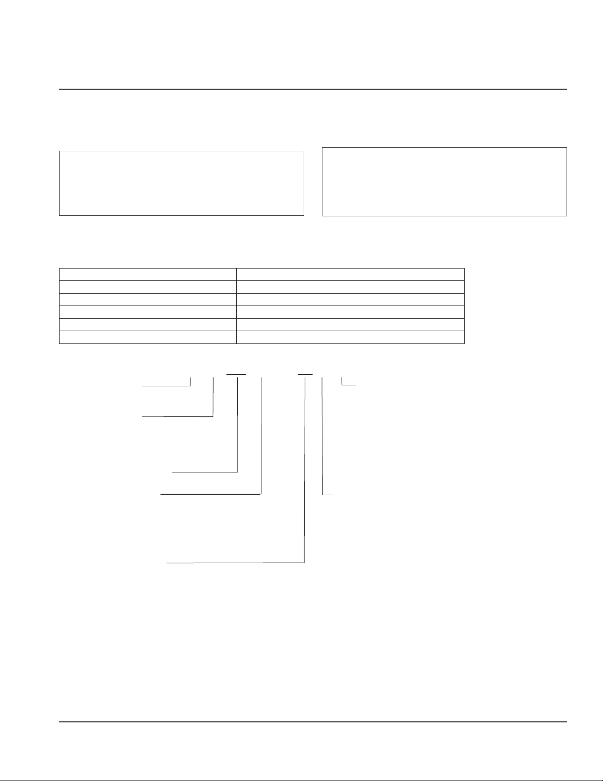
How To Read A Model Number
U G P 0040 A — 251 F D
Ice Machine Model Market Specific
Blank:Non-market specific
Refrigerant
P - R290
F - R404A
E - R134a
Nominal Production
Condenser Type
A - Self-Contained Air-Cooled
Voltage
161 - 115/60/1
261 - 208-230/60/1
251 - 230/50/1
S: Saudi Arabic
C:China
D: Germany
E: WARAS
N: Brazil
F=Schuko
G=Blade
Z=No Plug/Bare Lead
I=Oblique Flat Blades with Ground
B=115V Grounded Power Cord
Part Number: 040006977 09/22 3
Page 10
General Information Section 1
Model/Serial Number Location
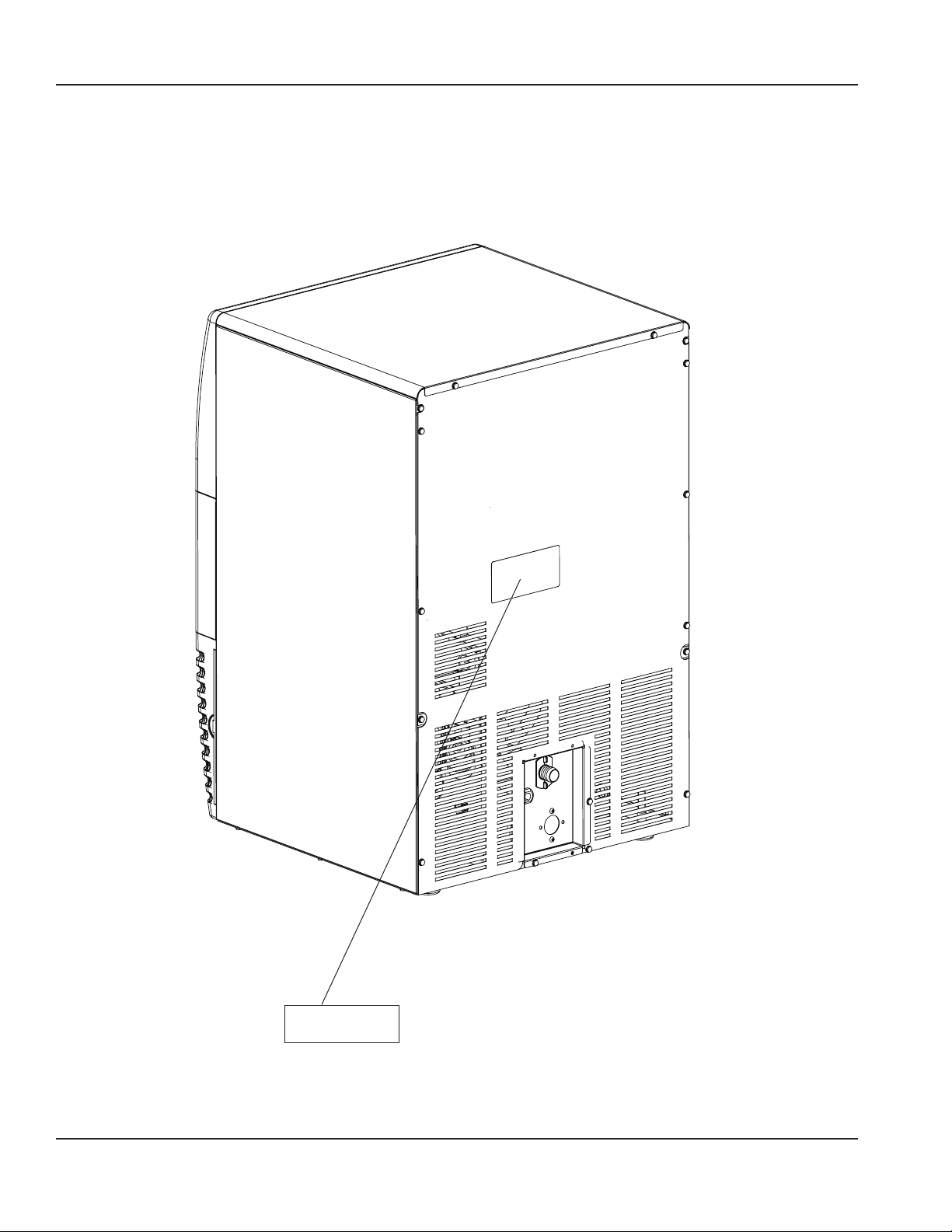
Record the model and serial number of your ice machine and
bin or dispenser in the space provided below. These numbers
are required when requesting information from your local
Manitowoc distributor, or Manitowoc China.
The model and serial number are listed on the OWNER
WARRANTY REGISTRATION CARD. They are also listed on the
MODEL/SERIAL NUMBER DECAL affixed to the ice machine,
remote condenser and storage bin.
Model/Serial
Number Location
4 Part Number: 040006977 09/22
Page 11

Section 1 General Information
Owner Warranty Registration Card
GENERAL
The packet containing this manual also includes warranty
information. Warranty coverage begins the day your new ice
machine is installed.
Important
Complete and mail the OWNER WARRANTY REGISTRATION
CARD as soon as possible to validate the installation date.
If you do not return your OWNER WARRANTY REGISTRATION
CARD, Manitowoc will use the date of sale to the Manitowoc
Distributor as the first day of warranty coverage for your new
ice machine.
Commercial Warranty Coverage
GENERAL
The following Warranty outline is provided for your
convenience.
Contact your local Manitowoc representative or Manitowoc
China. if you need further warranty information.
PARTS
Manitowoc warrants the ice machine against defects in
materials and workmanship, under normal use and service
for two (2) years from the date of original installation.
LABOR
Labor required to repair or replace defective components is
covered for one (1) year from the date of original installation.
Exclusions
The following items are not included in the ice machine’s
warranty coverage:
1. Normal maintenance, adjustments and cleaning as
outlined in this manual.
2. Repairs due to unauthorized modifications to the ice
machine or use of non-standard parts without prior
written approval from Manitowoc China.
3. Damage caused by improper installation of the ice
machine, electrical supply, water supply or drainage, or
damage caused by floods, storms, or other acts of God.
4. Premium labor rates due to holidays, overtime, etc.;
travel time; flat rate service call charges; mileage and
miscellaneous tools and material charges not listed on
the payment schedule. Additional labor charges resulting
from the inaccessibility of equipment are also excluded.
5. Parts or assemblies subjected to misuse, abuse, neglect
or accidents.
6. Damage or problems caused by installation, cleaning
and/or maintenance procedures inconsistent with the
technical instructions provided in this manual.
Authorized Warranty Service
To comply with the provisions of the warranty, a
refrigeration service company, qualified and authorized
by your Manitowoc distributor, or a Contracted Service
Representative must perform the warranty repair.
If the dealer you purchased the ice machine from is not
authorized to perform warranty service, contact your
Manitowoc distributor or Manitowoc China. for the name of
the nearest authorized service representative.
Service Calls
Normal maintenance, adjustments and cleaning as outlined
in this manual are not covered by the warranty. If you have
followed the procedures listed in this manual, and the ice
machine still does not perform properly, call your authorized
service company.
Part Number: 040006977 09/22 5
Page 12

General Information Section 1
THIS PAGE INTENTIONALLY LEFT BLANK
6 Part Number: 040006977 09/22
Page 13
Section 2
/
+
:
Installation
General
These instructions are provided to assist the qualified
installer.
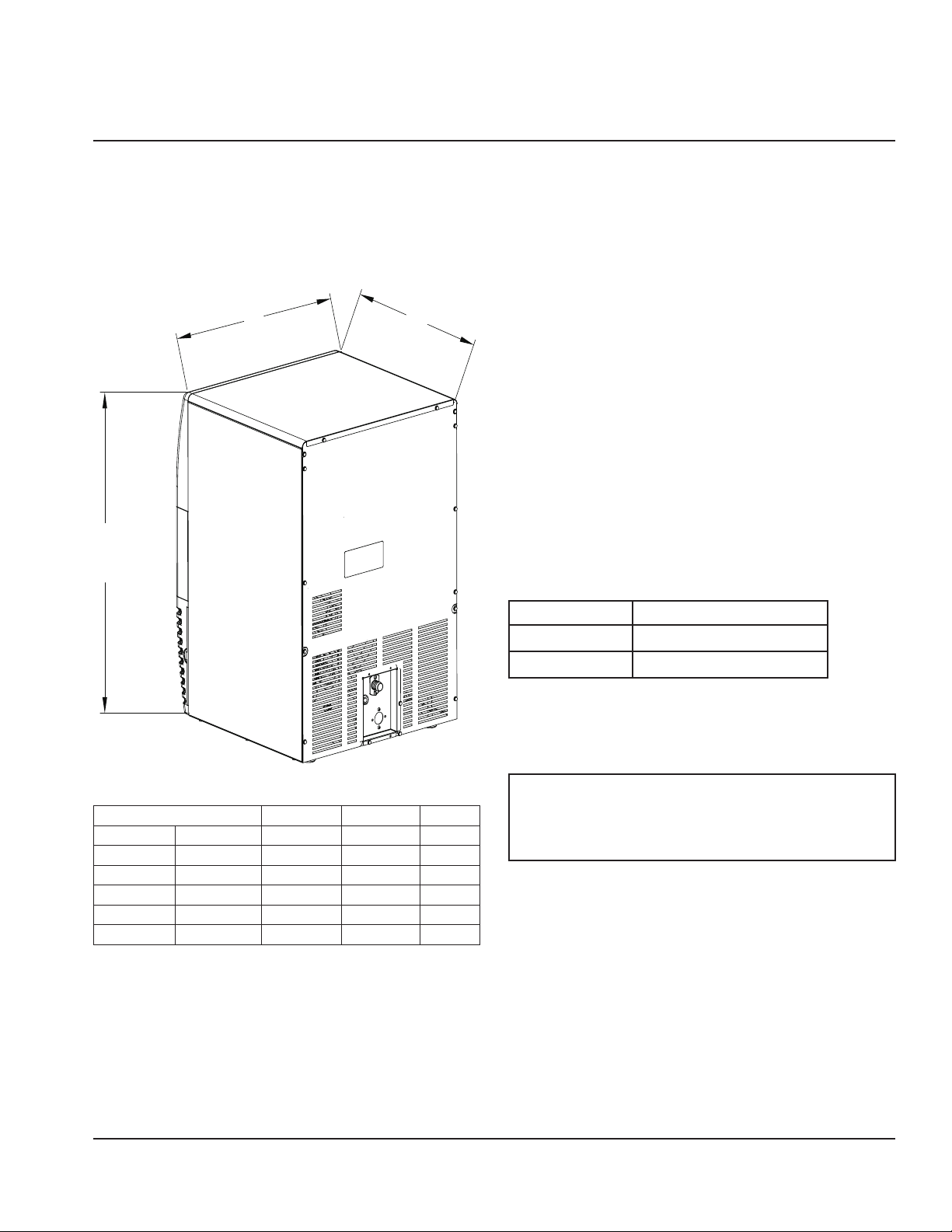
Ice Machine Dimensions
Location of Ice Machine
The location selected for the ice machine must meet the
following criteria. If any of these criteria are not met, select
another location.
1. The location must be indoors.
2. The location must be free of airborne and other
contaminants.
3. The air temperature must be at least 10°C (50°F), but
must not exceed 43°C (110°F).
4. The location must not be near heat-generating
equipment or in direct sunlight.
5. The location must be capable of supporting the weight
of the ice machine and a full bin of ice.
6. The location must allow enough clearance for water,
drain and electrical connections in the rear of the ice
machine.
7. The location must not obstruct airflow through or
around the ice machine (condenser airflow is in and
out the front). Refer to the chart below for clearance
recommendations:
Self-Contained Air-Cooled
Top/Sides
Back
NOTE: The ice machine may be built into a cabinet.
8”(203mm)
5”(127mm)
*
*
*There is no minimum clearance requirement for the top or
left and right sides of the ice machine. The listed values are
recommended for efficient operation and servicing only.
Caution
,
Model L W H
UG0020 mm 450 475 650
UG0030 mm 450 475 650
UG0040 mm 550 550 800
UG0050 mm 550 550 800
UG0065 mm 700 600 902
UG0080 mm 700 600 902
Part Number: 040006977 09/22 7
The ice machine must be protected if it will be subjected to
temperatures below 0°C (32°F). Failure caused by exposure
to freezing temperatures is not covered by the warranty.
Leveling the Ice Machine
Levelers are included with all ice machine. Legs are an
available option.
1. Screw the legs or levelers into the bottom of the ice
machine.
2. Screw the foot of each leg or leveler in as far as possible.
Move the ice machine into its final position.
3. Level the ice machine correctly. Use a level on top of the
ice machine. Turn each foot as necessary to level the ice
machine from front to back and side to side.
Page 14
Installation Section 2
Electrical Service
Warning
n
All wiring must conform to local, state and national codes.
The ice machine must be grounded in accordance with
national and local electrical codes.
VOLTAGE
The maximum allowable voltage variation is ±6% of the rated
voltage on the ice machine model/serial number plate at
start-up (when the electrical load is highest).
All ice machines are factory pre-wired with a 2 meter (6 ft)
power cord, no plug is supplied.
FUSE/CIRCUIT BREAKER
A separate fuse/circuit breaker must be provided for each ice
machine. An electrical disconnect switch must be provided if
the ice machine is hard wired (wired without a plug).
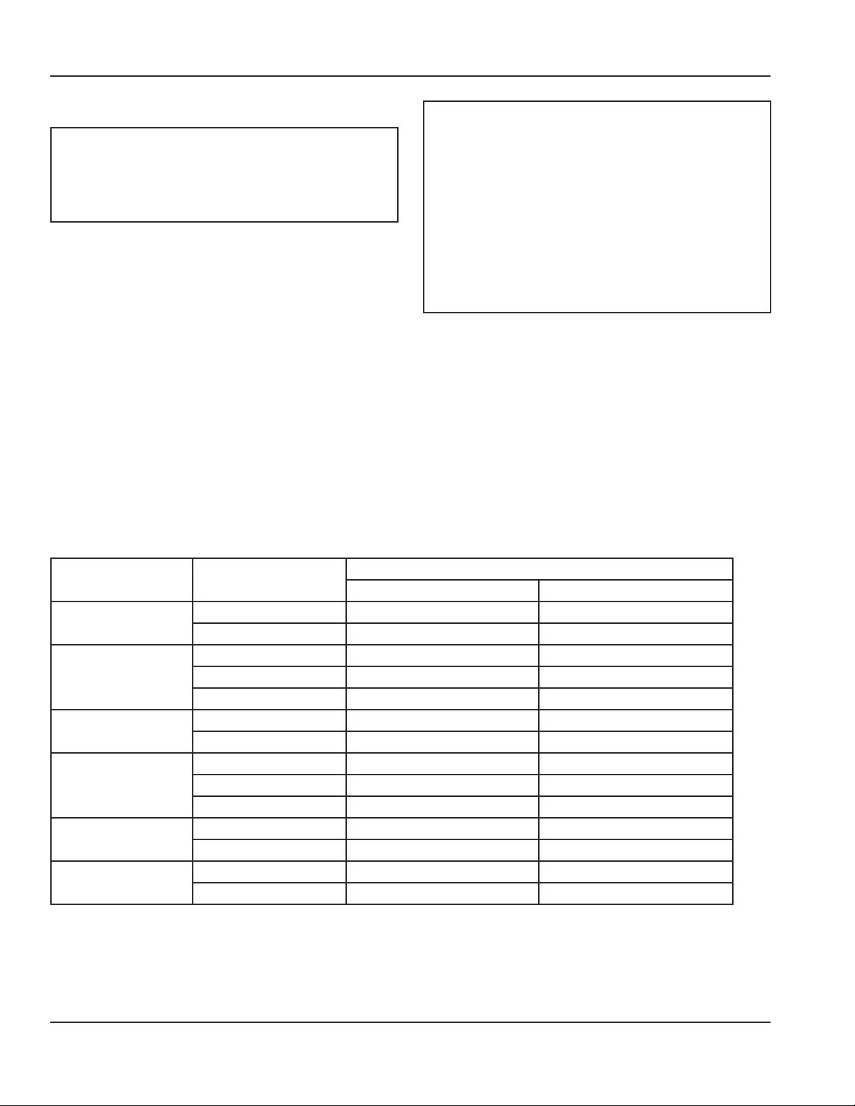
TOTAL CIRCUIT AMPACITY
The total circuit ampacity is used to help select the wire size
of the electrical supply.
The wire size (or gauge) is also dependent upon location,
materials used, length of run, etc., This must be determined
by a qualified electrician.
Warning
n
RISK OF ELECTRICAL SHOCK
FOR HARD WIRED(WIRED WITHOUT A PLUG) MACHINE,
IT MUST BE PROPERLY GROUNDED AND CONNECTED TO
THE FIELD WIRING TERMINAL IN ACCORDANCE WITH ALL
APPLICABLE NATIONAL AND LOCAL ELECTRICAL CODES BY
A QUALIFIED ELECTRICIAN. BEFORE CONNECTING WIRES,
DISCONNECT POWER AT THE ELECTRICAL DISCONNECT
AND LOCK OUT TO PREVENT ACCIDENTALLY ENERGIZING.
CONNECT ALL ELECTRICAL WIRING BEFORE USE - DO
NOT ENERGIZE ICE MACHINE UNTIL INSTALLATION IS
COMPLETE.
1. Connect –the three supply lead wires (Blue, Brown,
and Yellow/Green) to the field wiring terminal, “L”, “N”,
and “G”, the Yellow/Green wire must connect to the
“G”(ground).
2. After connecting the wiring to the terminal strip, the
supply lead must be secured to the cabinet with a strain
relief near the terminal strip.
3. Verify wiring is contained in the electrical wiring box
Ice Machine Voltage/Phase/Cycle
UG0020
UG0030
UG0040
UG0050
UG0065
UG0080
220/1/50 10 2.3
220/1/60 10 2.3
220/1/50 15 2.8
220/1/60 15 2.8
115/1/60 15 5.5
220/1/50 15 3.0
220/1/60 15 3.0
220/1/50 15 4.0
220/1/60 15 4.0
115/1/60 15 6.8
220/1/50 15 4.5
220/1/60 15 4.5
220/1/50 15 5.5
220/1/60 15 5.5
Air-Cooled
Maximum Fuse/Circuit Breaker Total Amps
8 Part Number: 040006977 09/22
Page 15
Section 2 Installation
Water Service/Drains
WATER SUPPLY
Local water conditions may require treatment of the water to
inhibit scale formation, filter sediment, remove chlorine, and
improve taste and clarity.
Important
If you are installing a water filter system, make sure that
you use a separate line for water-cooled condenser. Filter
life will be greatly reduced if filtered water is used for
water-cooled condenser.
WATER INLET LINES
Follow these guidelines to install water inlet lines:
1. Do not connect the ice machine to a hot water supply.
Be sure all hot water restrictors installed for other
equipment are working. (Check valves on sink faucets,
dishwashers, etc.)
2. Water pressure to the machine should be between 1.4
to 5.5 bar (20 to 80 psi).
3. If water pressure exceeds the maximum 5 bar
recommended pressure, obtain a water pressure
regulator from your Manitowoc distributor. Adjust
pressure to 2.5 bar (37 psi).
4. Install a water shut-off valve.
5. Connect to a potable water supply only.
DRAIN CONNECTIONS
Follow these guidelines when installing drain lines to prevent
drain water from flowing back into the ice machine and
storage bin:
1. Drain lines must have a 3.8 cm (1.5 inch) drop of run for
each meter (3 feet), and must not create traps.
2. The floor drain must be large enough to accommodate
drainage from all drains.
3. Run separate bin and water-cooled condenser drain
lines. Insulate them to prevent condensation by
temperature.
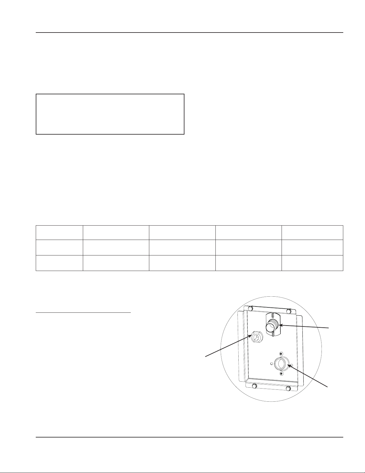
WATER SUPPLY AND DRAIN LINE SIZING/CONNECTIONS
Water Temperature Water Pressure Ice Machine Fitting
*
Ice Making
Water Inlet
**
Drain Connection
Outlet
1
Min. = Minimum
2
Max. = Maximum
* Water Inlet Hose Supplied With Machine.3/4” Female Pipe Thread/ 2 meters long.
** Drain Hose Supplied With Machine.7/8” (22.2mm) Hose/ 2 Meters Long.
50°F (10°C) Min.1
90°F (32.2°C) Max.
— — 7/8" Fitting Barbed
2
20 psi (137.9 kPa) Min.1
80 psi (551.5 kPa) Max.
INSTALLATION NOTE (SWITZERLAND)
The connection to the drinking water network must be made
with a certified backflow preventer type EA (EN13959) and
with a certified connection hose (EN13618 or EN61770) on
site.
2
Electrical
3/4" male pipe
thread
Tubing Size Up to Ice
Machine Fitting
1/2" (15 mm) minimum
inside diameter
3/4" (18 mm) minimum
inside diameter
Drain
Ice Making Water
Inlet
Typical Water Supply and Drain Line Sizing
and Connections
Part Number: 040006977 09/22 9
Page 16

Section 2 Installation
Installation Checklist
Is the ice machine level?
Has all of the internal packing been removed?
Have all of the electrical and water connections been
made?
Has the supply voltage been tested and checked against
the rating on the nameplate?
Are all components installed?
Has the ice machine been installed where ambient
temperatures will remain in the range of 50° - 110°F
(10° - 43°C)?
Has the ice machine been installed where the incoming
water temperature will remain in the range of 50° - 90°F
(10° - 32°C)?
Are all electrical leads free from contact with
refrigeration lines and moving equipment?
Has the owner/operator been instructed regarding
maintenance and the use of Manitowoc De-scaler and
Sanitizer?
Has the owner/operator completed the warranty
registration card?
Has the ice machine and bin been sanitized?
Has this manual been given to the owner/operator?
Is the ice-off-wash switch set to the ice position?
Before Starting the Ice Machine
All Manitowoc ice machines are factory-operated and
adjusted before shipment. Normally, new installations do not
require any adjustment.
To ensure proper operation, follow the Operational Checks.
Starting the ice machine and completing the Operational
Checks are the responsibilities of the owner/operator.
Adjustments and maintenance procedures outlined in this
manual are not covered by the warranty.
Warning
n
PERSONAL INJURY POTENTIAL
Do not operate equipment that has been misused, abused,
neglected, damaged, or altered/modified from that of
original manufactured specifications.
Part Number: 040006977 09/22 10
Page 17
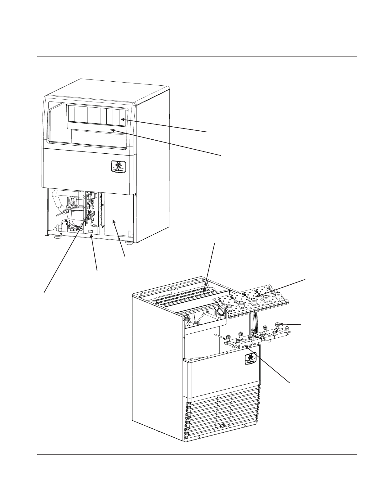
Component Identification
Section 3
Operation
Water Curtain
Water Sump Trough
Control Board
Air Cooled Condenser
On-off-wash Toggle Switch
Evaporator
Ice Chute
Spray Nozzles
Spray Bar
Part Number: 040006977 09/22 11
Page 18
Operation Section 3
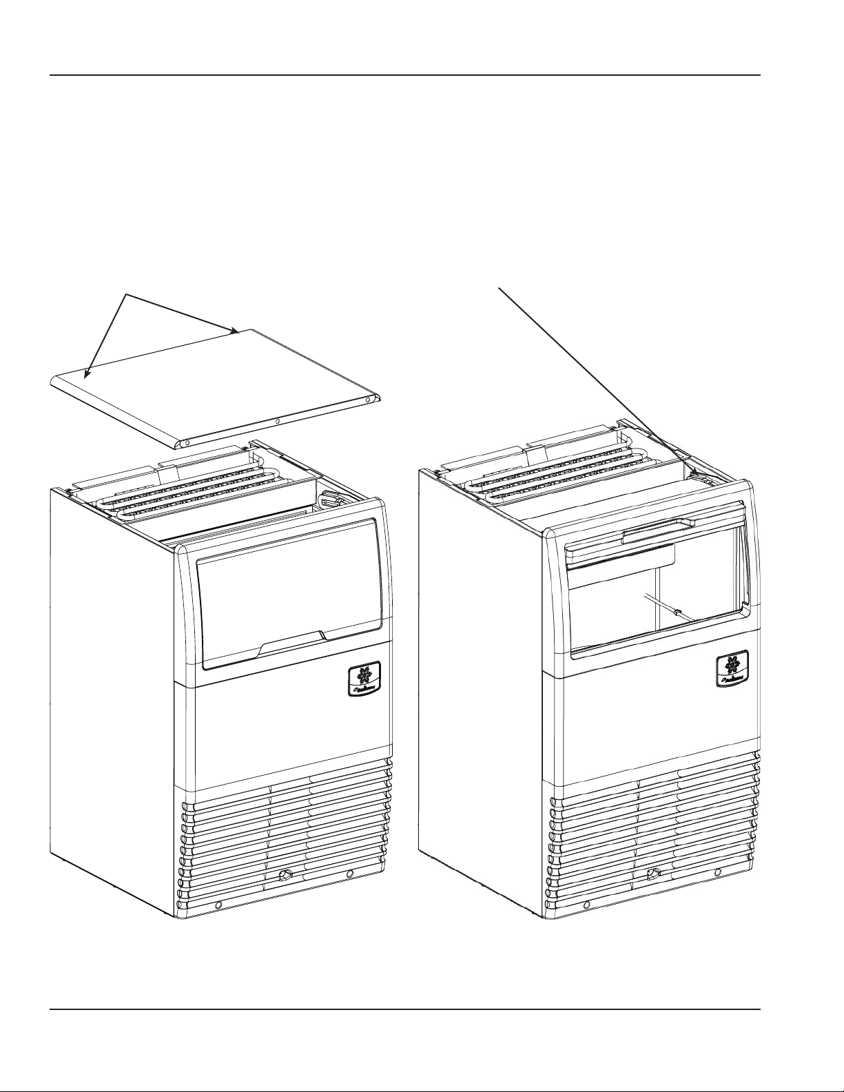
Componet Removal
TOP COVER
For easiest access to the evaporator compartment, the top
cover can be removed.
1. Remove two screws on the rear of the ice machine.
2. Slide top cover back to disengage the three pins from
the front panel.
Remove Two Screws-Slide
Cove Back To Remove
BIN DOOR
Allows access to the storage bin.
1. Remove top cover.
2. Slide door up until rear pins align with slot in door tracks.
3. Lift rear door pins out and slide door up until front door
pins align with slot.
4. Lift door out of door track
Align Door Pins With Track Slots
Then Lift Door Out of Track
12 Part Number: 040006977 09/22
Page 19

Section 3 Operation
WATER CURTAIN
The water curtain is designed to keep the spraying water
from escaping the evaporator compartment. Removal of the
bin door is not required, but enhances access.
Grasp the ice curtain and lift up.
To re-install into ice machine,pivot the water curtain and pull
down into position. Make sure tabs are secure in grooves.
ICE CHUTE
The ice chute is positioned over the spray nozzles and allows
the ice to easily fall into the bin. It must be firmly positioned
over the Spray Bar Assembly, with the front edge inside the
water trough or the spray nozzles will not be aligned with the
spray holes, and spray water will fall into bin.
1. Grab protruding spray holes on one end and lift up.
2. Pivot ice chute and remove.
3. To re-install ice chute, grasp protruding spray holes
and position over Spray Bar Assembly. Make sure rear
supports are over Spray Bar Assembly, and front edge is
inside of water trough.
Ice Chute
Water Curtain
Part Number: 040006977 09/22 13
Page 20
Operation Section 3
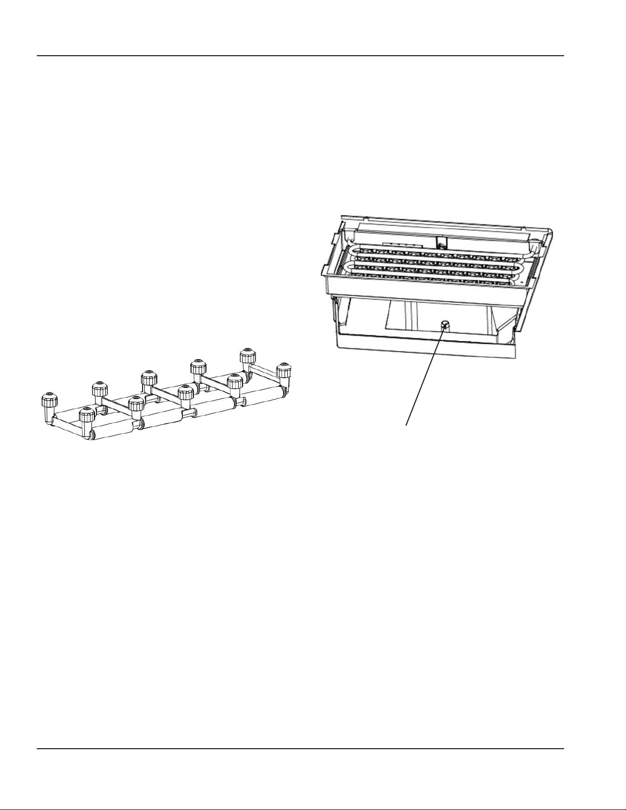
SPARY BAR
The spray bar supplies water to the individual ice-making
cups. Water from the Water Pump sprays through the
nozzles, located on the upper portion of the tubes.
1. Grasp one end of the spray bar, lift up and remove from
seat formed in water trough.
2. Remove both plastic clips on water inlet tubing by
grasping both ears on clip and separating.
3. Apply food grade lubricate to ease re-assembly of spray
bar components when necessary.
4. To re-install spray bar, position water inlet tubing on inlet
ports, and squeeze clips until tight.
5. Reposition assembly on water trough seat.
Nozzles and inserts can be removed for cleaning by
unscrewing nozzles. Inserts are located inside the spray bar
ports. The spray bar also disassembles for easy cleaning.
SUMP DRAIN OVERFLOW TUBE
The sump drain overflow tube is located in the evaporator
water sump.
1. Remove shutters and ice chute.
2. Lift spray bar or disconnect and remove for easiest
access.
3. Pull up on over flow tube to remove.
4. To replace plug, insert in hole, and push with force to
make a tight seal.
Overow Tube
14 Part Number: 040006977 09/22
Page 21

Section 3 Operation
Ice Making Sequence of Operation
INITIAN START-UP
1. Water Inlet and Pressure Equalization
Turn the toggle switch to”ON” position,the water fill valve
and harvest valve are energized, 300 seconds later, the
water fill valve is de-energized. 20seconds after the harvest
valve solenoid is energized, the compressor is energized.
300seconds after the compressor is energized, the harvest
valve solenoid is de-energized, the water pump and the fan
motor are energized,machine goes into freeze cycle.
2. Freeze Cycle
The pump sprays water into the inverted cups. The water
freezes layer by layer, until an ice cube forms in each cup.
When the”water temperature”is equal to or less than 2 °C for
more than 5 seconds, control will read
the” liquid line temperature” and dip switch setting , get the”
freeze postpone time” and “fan shut off time”.Board will shut
the Fan before the end of the freeze cycle to assist harvest.
When the ” freeze postpone time” has elapsed, the harvest
cycle is initiated.
3. Harvest Cycle
The compressor continues to operate and the water pump is
de-energized. The hot gas valve energizes, allowing hot gas
to enter and warm the evaporator. The water valve is also
energized, aiding with harvest, as well as filling up the sump
with fresh water for a new freeze cycle.
At the point of 2 minutes to freeze end , board will read the
“ liquid line temperature”again and calculate the “harvest
time”
The ice falls from the cups and is directed into the bin by the
ice chute. The harvest cycle continues until the harvest time
has elapsed, then machine goes into a new freeze cycle
4. Automatic Shut-Off
When the storage bin is full, the ice will come in contact
with the bin thermostat which is located inside the bin.
The machine will stop after approximately 45seconds of
continuous ice contact with the bin thermostat probe.
The ice machine remains off until a 3 minutes delay has
elapsed and enough ice has been removed from the storage
bin to allow the ice to fall clear of the bin thermostat probe.
As the ice clears the probe, the bin thermostat warms up and
the machine starts another freeze cycle.
Part Number: 040006977 09/22 15
Page 22
Operation Section 3
Operational Checks
GENERAL
Your ice machine was factory-operated and adjusted before
shipment. Normally, a newly installed ice machine does not
require any adjustment.
To ensure proper operation, always follow these Operational
Checks when starting the ice machine:
• for the first time
• after a prolonged out of service period
• after de-scaling and sanitizing
Routine adjustments and maintenance procedures outlined
in this manual are not covered by the warranty.
Important
It is recommended that adjustments made to this ice
machine be made by a qualified technician. Improper
adjustment, may seriously affect the life of this ice
machine.
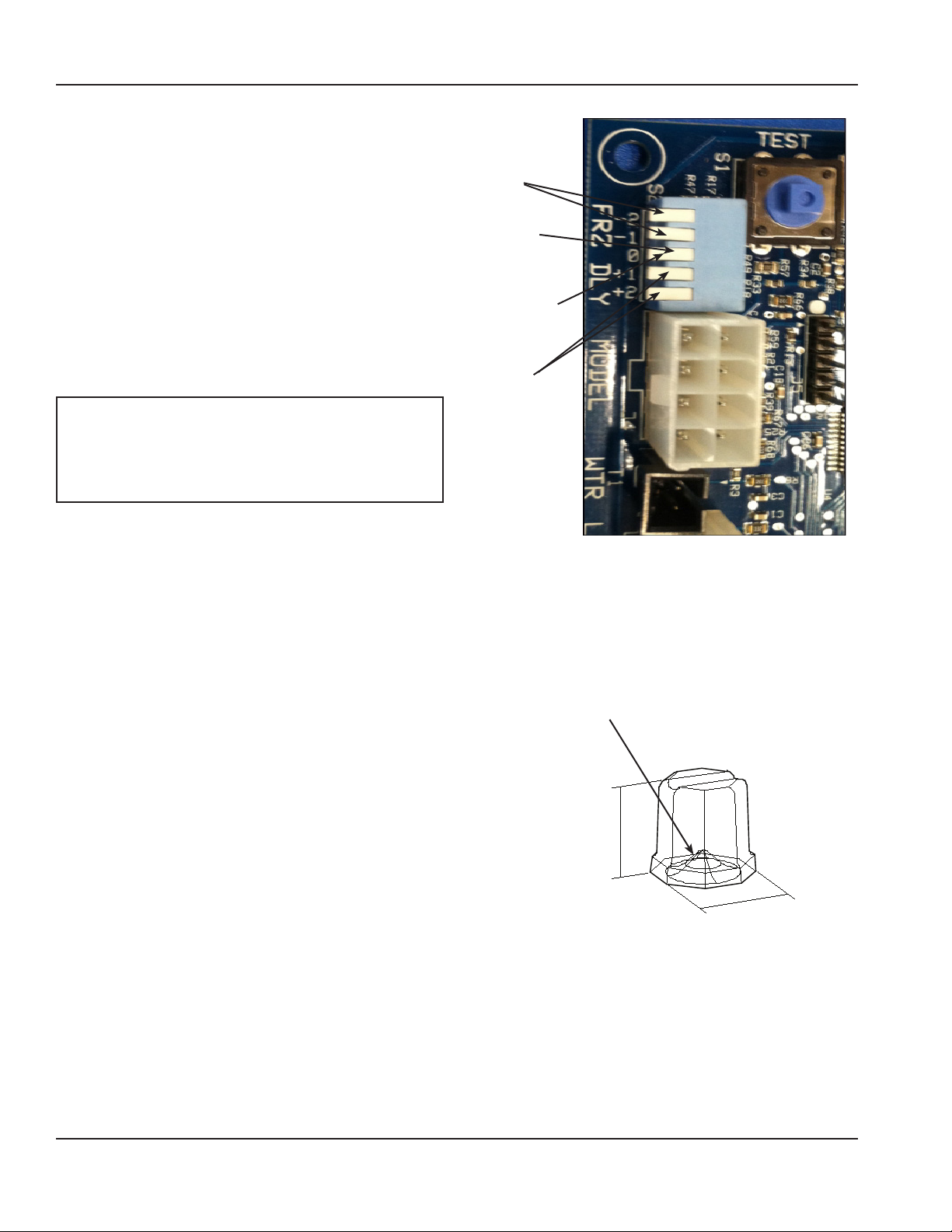
ICE CUBE THICKNESS CHECK
The ice cube thickness is factory-set to maintain the ice cube
thickness at the proper size and weight.
1. Allow the ice machine to operate for three complete
cycles. The cubes should have a small dimple in the
center.
2. Cycle times vary, according to surrounding air and water
inlet temperatures.
3. If cubes are not full (large dimple), raise the “dip
switch” level to increase cube size. Allow ice machine to
complete three cycles, then check cube.
4. If cubes are too full, ( no dimple), lower the “dip switch”
level to decrease cube size.Allow ice machine to operate
three complete cycles.
5. The “dip switch” can be adjusted to five levels: -2/1/0/+1/+2, and ensure that only one level switch is
pressed.
Decrease
Cube Size
Dip Switch
Factory
Default
Setting
Increase
Cube Size
CUBE SHAPE
The standard cube has an average weight of 19 grams, Notice
the normal dimple in the center of the cube.
Dimple
34
Standard Cube 19g
16 Part Number: 040006977 09/22
Page 23
Section 4
Maintenance
General
The end user is responsible for maintaining the ice machine
in accordance with the instructions in this manual.
Maintenance procedures are not covered by the warranty.
Caution
,
If you do not understand the procedures or the safety
precautions that must be followed, call your local service
representative to perform the necessary maintenance
procedures for you.
Maintenance Weekly Monthly Semi Annual Annual
Clean cabinet exterior X X X
Sanitize Ice Bin X X X
Clean Evaporator X S S
Sanitize Evaporator X S S S
Clean Condenser Coil X S S
Check Ice Quality X S S S
X= End User
S=Service Company
Basic hygiene and maintenance of your Ice Machine, will
increase its reliability, increase performance, and help
save on water and power consumption. Ice production
will be maintained within the manufacturers guidelines,
and unwanted repairs due to maintenance issues will be
minimized.
The chart below is an overview of the maintenance that
the end user and service technician should perform, and
the frequency. These figures are the minimum required. If
the Ice Machine is supplied with hard water, more frequent
evaporator de-scaling should be performed. If the condenser
air filter is totally blocked, after one week, more frequent
cleaning is recommended.
After prolonged
shutdown
At Start-up
Part Number: 040006977 09/22 17
Page 24
Maintenance Section 4
De-scaling and Sanitizing
GENERAL
De-scale and sanitize the ice machine every six months for
efficient operation. If the ice machine requires more frequent
de-scaling, consult a qualified service company to test the
water quality and recommend appropriate water treatment.
An extremely dirty ice machine must be taken apart for descaling and sanitizing.
NOTE: Sanitizing can be performed independently and more
frequently than de-scaling if desired.
Caution
,
Use only approved Ice Machine Cleaner and Sanitizer
(Manitowoc De-scaler part number 000000084 and
Manitowoc Sanitizer part number 9405653). Read and
understand all labels printed on bottles before use. Do not
mix Ice Machine De-scaler and Sanitizer solutions together
Warning
n
Wear rubber gloves and safety goggles (and/or face shield)
when handling Ice Machine De-scaler or Sanitizer.
DETAILED DE‑SCALING/SANITIZING PROCEDURE
This procedure must be performed a minimum of once every
six months.
• The ice machine and bin must be disassembled de-scaled
and sanitized.
• All ice produced during the de-scaling and sanitizing
procedures must be discarded.
REMEDIAL DE‑SCALING PROCEDURE
• This procedure de-scales all components in the waterflow
path, and is used between the bi-yearly detailed
Detailed De-scaling and Sanitizing procedure
DE‑SCALING PROCEDURE
Ice machine de-scaler is used to remove lime scale or other
mineral deposits. Sanitizer is used to remove algae or slime.
Mix 4 liters of water with 500 ml of de-scaler in a plastic or
stainless container.
De-scaler Water
500 ml (16 oz) 4 L (1 gal)
Step 1 Set the toggle switch to the OFF position at the end
of a Harvest Cycle, after ice releases from the evaporator. Or,
set the switch to the OFF position and allow the ice to melt
off the evaporator.
Caution
,
Never use anything to force ice from the evaporator.
Damage may result.
Step 2 Remove all ice from the bin.
Step 3 Remove all parts as described in Section 3
“Componet Removal” on page 12.
Step 4 Take all components to sink and with 2 liters Descaler/Water mixture clean all components with a soft nylon
brush. Disassemble spray bar, remove nozzles and inserts and
soak for 5 minutes. For heavily scaled parts, soak in solution
for 15–20 minutes. Rinse all components with clean water.
Cleaning the Condenser
Step 5 While components are soaking; use nylon brush to
scrub inside of ice bin. Scrub inside of door, door track, bin,
sump trough, and evaporator moldings. With clean water,
rinse all of these areas thoroughly.
Step 6 Replace sump overflow tube and pour remaining 2
liters of mixture into the water sump. Replace all parts.
Step 7 To start a standard cleaning cycle, press the toggle
switch to WASH position and hold for 5 seconds.
Step 8 Wait until the cleaning cycle is complete
(approximately 13.5 minutes). Remove water curtain, ice
chute and over flow tube from the water sump. Allow all
water to drain from the sump. Replace drain plug.Press the
toggle switch to WASH position and hold for 5 seconds to
start a rinsing cycle.
Step 9 Wait until the rinsing cycle is complete
(approximately 12 minutes). Remove water curtain, ice
chute, water sump over flow tube. Drain water from sump
and replace tube.
18 Part Number: 040006977 09/22
Page 25
Section 4 Maintenance
SANITIZINGING PROCEDURE
NOTE: Sanitizing can be performed independently and more
frequently than de-scaling if desired.
Step 10 Mix 60 ml of sanitizer with 12 l of water in a plastic
or stainless steel container.
Sanitizer Water
60 ml (2 oz) 12 L (3 gal)
Step 11 Remove Water Curtain and Ice Chute as described
in Section 3 “Componet Removal” on page 12.
Step 12 Take all components to sink and with 10 liters
Sanitizer/Water mixture sanitize all components with a soft
nylon brush or cloth. Do not rinse components.
Step 13 Use brush or cloth to sanitize the inside of ice bin.
Scrub inside of door, door track, bin, water sump, water
distribution assembly and evaporator moldings. Do not rinse.
Step 14 Replace sump drain over flow tube, and transfer
remaining 2 liters of solution to the sump trough. Replace all
components.
Step 15 To start a standard sanitizing cycle, press the toggle
switch to WASH position and hold for 5 seconds.
Step 16 Wait until the cleaning cycle is complete
(approximately 13.5 minutes). Remove water curtain and ice
chute Remove over flow tube from water sump and allow
all water to drain from sump. Replace drain plug. Press the
toggle switch to WASH position and hold for 5 seconds to
start a rinsing cycle.
Step 17 Wait until the rinsing cycle is complete
(approximately 12 minutes). Remove water curtain, ice
chute, water sump over flow tube. Drain water from sump
and replace tube.
Cleaning the Condenser
Warning
n
Disconnect electric power to the ice machine at the
electric service switch before performing maintenance on
equipment.
AIR‑COOLED CONDENSER
A dirty condenser restricts airflow, resulting in excessively
high operating temperatures. This reduces ice production
and shortens component life.
Clean the condenser at least every six months.
1. Remove Plastic Front Grill removing two Phillips head
screws. Clean Grill openings before replacing.
2. Clean the outside of the condenser with a soft brush
or a vacuum with a brush attachment. Clean from top
to bottom, not side to side. Be careful not to bend the
condenser fins.
3. Shine a flashlight through the condenser to check for dirt
between the fins. If dirt remains:
A. Blow compressed air through the condenser fins. Be
careful not to bend the fan blades.
B. If dirt or grease remains between fins, consult your
service representative.
Warning
n
The condenser fins are sharp. Use care when cleaning
them.
Step 18 Replace all parts.
Step 19 Place toggle switch to ON position,ice machine will
go into ice making cycle.
NOTE: To terminate a standard cleaning cycle, press the
toggle switch to WASH position and hold more than 30
seconds
Caution
,
If the de-scaler /sanitizer solution has been poured into
the water trough, then the standard cleaning cycle must be
completed. Don’t terminate the cleaning cycle, or the ice
machine will not purges the remaining de-scaler /sanitizer
solution from the water trough.
Part Number: 040006977 09/22 19
Page 26
Maintenance Section 4
Exterior Cleaning
Clean the area around the ice machine as often as necessary
to maintain cleanliness and efficient operation.
Sponge any dust and dirt off the outside of the ice machine
with mild soap and water. Wipe dry with a clean, soft cloth.
A commercial grade stainless steel cleaner and polish may be
used.
Removal from Service/Winterization
GENERAL
Special precautions must be taken if the ice machine is to
be removed from service for an extended period of time or
exposed to ambient temperatures of 0°C (32°F) or below.A
dirty condenser restricts airflow, resulting in excessively high
operating temperatures. This reduces ice production and
shortens component life. Clean the condenser at least every
six months. Follow the steps below.
Caution
,
If water is allowed to remain in the ice machine in freezing
temperatures, severe damage to some components could
result. Damage of this nature is not covered by the warranty.
AIR‑COOLED ICE MACHINES
1. Disconnect the electric power at the circuit breaker or
the electric service switch.
2. Turn off the water supply.
3. Drain the water from the water sump and water pump
by disconnecting the water pump tubing.
4. Disconnect and drain the incoming ice-making water
line and disconnect the tubing from the water inlet valve
outlet and allow water to drain.
5. Blow compressed air in the drain opening and water
valve outlet hose, then reattach.
6. Make sure water is not trapped in any of the water or
drain lines.
Follow the applicable procedure below.
20 Part Number: 040006977 09/22
Page 27
Section 5
Troubleshooting
Checklist
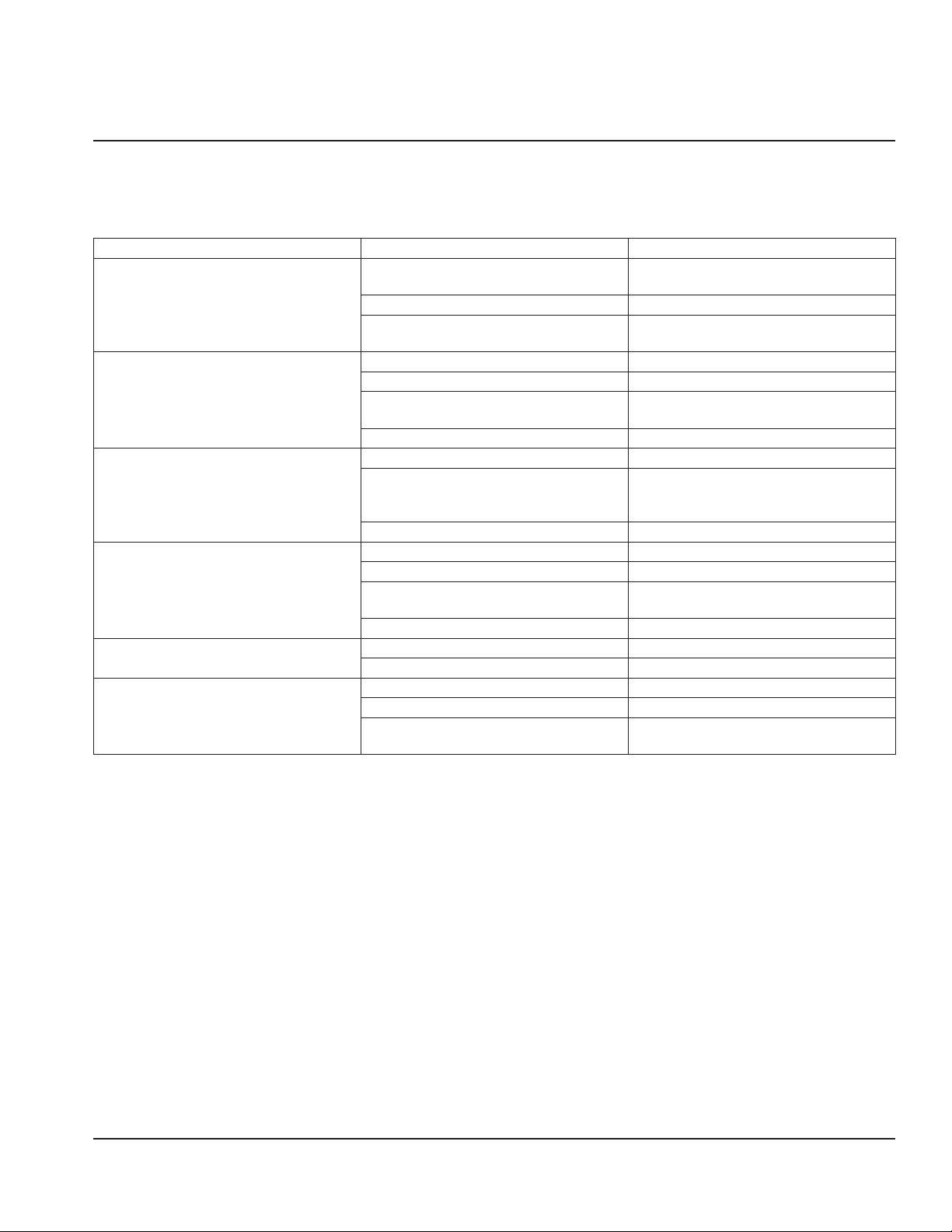
If a problem arises during operation of your ice machine, follow the checklist below before calling service. Routine adjustments
and maintenance procedures are not covered by the warranty.
Problem Possible Cause To Correct
Ice machine does not run.
Ice machine runs and no ice is produced
Freeze cycle long – low production
Shallow, incomplete or white ice cubes
Will not initiate a harvest cycle
Ice cubes do not release
No Power – Breaker off, fuse blown,
unplugged
Toggle switch is not in ice position Place toggle switch in ice position
The storage bin is full
No water to ice machine Correct water supply
Water sump overflow tube out of position Reposition/install overflow tube
Water sump thermistor or liquid line
thermistor faulty
Control board problem Call for service
Dirty condenser. Clean condenser
Water temperature too high
Refrigeration problem Call for service
Ice machine is dirty De-scale & sanitize the ice machine
Water pressure supply incorrect Verify water pressure is correct
Air temperature around ice machine is too
high
Dip switch incorrectly adjusted Adjust Dip switch
Liquid line thermistor faulty Replace the thermistor
Control board problem Call for service
Ice machine is dirty De-scale and sanitize the ice machine
Low ambient around ice machine Move ice machine to warmer area
Dip switch incorrectly adjusted (cubes too
large)
Restore power
Remove enough ice from the bin and wait for
3 minutes delay to expire.
Replace the thermistor
Connect to a cold water supply, verify check
valves in faucets and other equipment work
properly
Vent area or move ice machine
Adjust Dip switch
Part Number: 040006977 09/22 21
Page 28
MANITOWOC ICE
2110 SOUTH 26TH STREET, MANITOWOC, WI 54220
844-724-2273
WWW.MANITOWOCICE.COM
©2018 Manitowoc. except where explicitly stated otherwise. All rights reserved.
Part Number: 040006977 Rev. 02 09/22
 Loading...