

Manitowoc UR0140A, UD0140W, UD0140AE, UY0140AE, UR0140AE Installation, Operation And Maintanance Manual
...Page 1
NEO™ Ice Machines
UnderCounter - Air-cooled & Water-cooled
Installation, Operation and Maintenance Manual
This manual is updated as new information and models are released. Visit our website for the latest manual.
Part Number: 040002909 11/13
Page 2

Page 3

Section 1
General Information
Model Numbers . . . . . . . . . . . . . . . . . . . . . . . . . . . . . . . . . . . . . . . . . . . . . . . . . . . . 3
Accessories . . . . . . . . . . . . . . . . . . . . . . . . . . . . . . . . . . . . . . . . . . . . . . . . . . . . . . . 5
Section 2
Installation Instructions
Location of Ice Machine . . . . . . . . . . . . . . . . . . . . . . . . . . . . . . . . . . . . . . . . . . . . . 7
Ice Machine Heat of Rejection . . . . . . . . . . . . . . . . . . . . . . . . . . . . . . . . . . . . . . . . 7
Leveling the Ice Machine . . . . . . . . . . . . . . . . . . . . . . . . . . . . . . . . . . . . . . . . . . . . . 7
Electrical Service . . . . . . . . . . . . . . . . . . . . . . . . . . . . . . . . . . . . . . . . . . . . . . . . . . . 8
Water Service/Drains . . . . . . . . . . . . . . . . . . . . . . . . . . . . . . . . . . . . . . . . . . . . . . . . 10
Water Supply and Drain Line Sizing/Connections . . . . . . . . . . . . . . . . . . . . . . . . 11
Before Starting the Ice Machine . . . . . . . . . . . . . . . . . . . . . . . . . . . . . . . . . . . . . . . 12
Installation Checklist . . . . . . . . . . . . . . . . . . . . . . . . . . . . . . . . . . . . . . . . . . . . . . . . 12
Table of Contents
Bin Caster . . . . . . . . . . . . . . . . . . . . . . . . . . . . . . . . . . . . . . . . . . . . . . . . . . . . . 5
Arctic Pure Water Filter System . . . . . . . . . . . . . . . . . . . . . . . . . . . . . . . . . . . . 5
Manitowoc Cleaner and Sanitizer . . . . . . . . . . . . . . . . . . . . . . . . . . . . . . . . . . . 5
General . . . . . . . . . . . . . . . . . . . . . . . . . . . . . . . . . . . . . . . . . . . . . . . . . . . . . . . 8
Voltage . . . . . . . . . . . . . . . . . . . . . . . . . . . . . . . . . . . . . . . . . . . . . . . . . . . . . . . 8
Fuse/Circuit Breaker . . . . . . . . . . . . . . . . . . . . . . . . . . . . . . . . . . . . . . . . . . . . . 8
Total Circuit Ampacity . . . . . . . . . . . . . . . . . . . . . . . . . . . . . . . . . . . . . . . . . . . . 8
Ground Fault Circuit Interrupter . . . . . . . . . . . . . . . . . . . . . . . . . . . . . . . . . . . . 8
Electrical Specifications . . . . . . . . . . . . . . . . . . . . . . . . . . . . . . . . . . . . . . . . . . 9
Water Supply . . . . . . . . . . . . . . . . . . . . . . . . . . . . . . . . . . . . . . . . . . . . . . . . . . 10
Water Inlet Lines . . . . . . . . . . . . . . . . . . . . . . . . . . . . . . . . . . . . . . . . . . . . . . . . 10
Drain Connections . . . . . . . . . . . . . . . . . . . . . . . . . . . . . . . . . . . . . . . . . . . . . . 10
Cooling Tower Applications . . . . . . . . . . . . . . . . . . . . . . . . . . . . . . . . . . . . . . . 10
Water Level Adjustment . . . . . . . . . . . . . . . . . . . . . . . . . . . . . . . . . . . . . . . . . . 11
Water/Drain Connections . . . . . . . . . . . . . . . . . . . . . . . . . . . . . . . . . . . . . . . . . 11
Section 3
Operation
Touch Pad Features . . . . . . . . . . . . . . . . . . . . . . . . . . . . . . . . . . . . . . . . . . . . . . . . . 13
On/Off . . . . . . . . . . . . . . . . . . . . . . . . . . . . . . . . . . . . . . . . . . . . . . . . . . . . . . . . 13
Delay . . . . . . . . . . . . . . . . . . . . . . . . . . . . . . . . . . . . . . . . . . . . . . . . . . . . . . . . . 13
Clean . . . . . . . . . . . . . . . . . . . . . . . . . . . . . . . . . . . . . . . . . . . . . . . . . . . . . . . . . 13
Bin Full . . . . . . . . . . . . . . . . . . . . . . . . . . . . . . . . . . . . . . . . . . . . . . . . . . . . . . . 13
Service . . . . . . . . . . . . . . . . . . . . . . . . . . . . . . . . . . . . . . . . . . . . . . . . . . . . . . . 13
Ice Making Sequence of Operation . . . . . . . . . . . . . . . . . . . . . . . . . . . . . . . . . . . . 14
Safety Limits . . . . . . . . . . . . . . . . . . . . . . . . . . . . . . . . . . . . . . . . . . . . . . . . . . . 14
Part Number 040002909 11/13 1
Page 4

Section 4
Maintenance
Section 5
Customer Support
Table of Contents (continued)
Interior Cleaning and Sanitizing . . . . . . . . . . . . . . . . . . . . . . . . . . . . . . . . . . . . . . . 15
General . . . . . . . . . . . . . . . . . . . . . . . . . . . . . . . . . . . . . . . . . . . . . . . . . . . . . . . 15
Cleaning and Sanitizing Procedure . . . . . . . . . . . . . . . . . . . . . . . . . . . . . . . . . . 15
Remove Parts for Cleaning . . . . . . . . . . . . . . . . . . . . . . . . . . . . . . . . . . . . . . . . 17
Preventative Maintenance Cleaning . . . . . . . . . . . . . . . . . . . . . . . . . . . . . . . . . . . . 19
Ice Machine Inspection . . . . . . . . . . . . . . . . . . . . . . . . . . . . . . . . . . . . . . . . . . . . . . 19
Exterior Cleaning . . . . . . . . . . . . . . . . . . . . . . . . . . . . . . . . . . . . . . . . . . . . . . . . . . . 19
Cleaning the Condenser . . . . . . . . . . . . . . . . . . . . . . . . . . . . . . . . . . . . . . . . . . . . . 20
General . . . . . . . . . . . . . . . . . . . . . . . . . . . . . . . . . . . . . . . . . . . . . . . . . . . . . . . 20
Removal from Service/Winterization . . . . . . . . . . . . . . . . . . . . . . . . . . . . . . . . . . . 20
Checklist . . . . . . . . . . . . . . . . . . . . . . . . . . . . . . . . . . . . . . . . . . . . . . . . . . . . . . . . . . 21
Safety Limit Feature . . . . . . . . . . . . . . . . . . . . . . . . . . . . . . . . . . . . . . . . . . . . . . . . . 22
Commercial Ice Machine Warranty . . . . . . . . . . . . . . . . . . . . . . . . . . . . . . . . . . . . . 23
Residential Ice Machine Limited Warranty . . . . . . . . . . . . . . . . . . . . . . . . . . . . . . . 24
2 Part Number 040002909 11/13
Page 5

Section 1
!
Warning
!
Caution
Important
!
Warning
General Information
Model Numbers
This manual covers the following models:
Self-Contained
Air-Cooled
UD0140A UD0140W
UD0140AE --
UY0140A UY0140W
UY0140AE --
UR0140A --
UR0140AE --
UD0190A --
UD0190AE --
UY0190A --
UY0190AE --
UR0190A --
UR0190AE --
UD0240A UD0240W
UD0240AE UD0240WE
UY0240A UY0240W
UY0240AE UY0240WE
UR0240A --
UR0240AE --
UD0310A UD0310W
UD0310AE --
UY0310A UY0310W
UY0310AE --
UR0310A UR0310W
UR0310AE --
Self-Contained
Water-Cooled
Read These Before Proceeding:
Do not operate equipment that has been misused,
abused, neglected, damaged, or altered/modified
from that of original manufactured specifications.
This appliance is not intended for use by persons
(including children) with reduced physical, sensory
or mental capabilities, or lack of experience and
knowledge, unless they have been given
supervision concerning use of the appliance by a
person responsible for their safety. Do not allow
children to play with this appliance.
Proper installation, care and maintenance are
essential for maximum performance and troublefree operation of your equipment. Visit our website
www.manitowocfsg.com for manual updates,
translations, or contact information for service
agents in your area.
Routine adjustments and maintenance procedures
outlined in this manual are not covered by the
warranty.
Part Number 040002909 11/13 3
Read this manual thoroughly before operating,
installing or performing maintenance on the
equipment. Failure to follow instructions in this
manual can cause property damage, injury or death.
Page 6
General Information Section 1
!
Warning
!
Warning
!
Warning
!
Warning
!
Warning
!
Warning
!
Warning
!
Warning
!
Warning
!
Warning
!
Warning
!
Warning
!
Warning
Do not use electrical appliances or accessories
other than those supplied by Manitowoc for your ice
machine model.
Personal injury is possible when moving this
equipment. Two or more people aware of the
possible lifting and moving hazards are required
when moving or relocating this equipment.
This equipment contains high voltage electricity and
refrigerant charge. Installation and repairs are to be
performed by properly trained technicians aware of
the dangers of dealing with high voltage electricity
and refrigerant under pressure. The technician must
also be certified in proper refrigerant handling and
servicing procedures. All lockout and tag out
procedures must be followed when working on this
equipment.
Do not clean with water jet.
It is the responsibility of the equipment owner to
perform a Personal Protective Equipment Hazard
Assessment to ensure adequate protection during
maintenance procedures.
Only trained and qualified personnel aware of the
dangers of refrigerant under pressure, electrical
shock, and incorrect lifting/moving hazards, should
install, maintain or service this equipment.
Read this manual thoroughly before operating,
installing or performing maintenance on the
equipment.
Do not damage the refrigeration circuit when
installing, maintaining or servicing the unit.
All covers and access panels must be in place and
properly secured, before operating this equipment.
Do not obstruct machine vents or openings.
Do not store gasoline or other flammable vapors or
liquids in the vicinity of this or any other appliance.
Do not damage the refrigeration circuit when
installing, maintaining or servicing the unit.
Clean up any water or ice on counter or floor to
prevent personal injuries. Always inspect the
equipment for leakage after cleaning, maintenance
or service procedures are performed.
4
Part Number 040002909 11/13
Page 7

Section 1 General Information
Accessories
Contact your Manitowoc distributor for these optional
accessories:
BIN CASTER
Replaces standard legs.
ARCTIC PURE WATER FILTER SYSTEM
Engineered specifically for Manitowoc ice machines,
Arctic Pure water filters are an efficient, dependable, and
affordable method of inhibiting scale formation, filtering
sediment, and removing chlorine taste and odor.
MANITOWOC CLEANER AND SANITIZER
Manitowoc Ice Machine Cleaner and Sanitizer are
available in convenient 16 oz. (473 ml) and 1 gal (3.78 l)
bottles. These are the only cleaner and sanitizer
approved for use with Manitowoc products.
Cleaner Part Number Sanitizer Part Number
16oz 94-0456-3 16oz 94-0565-3
1 Gallon 94-0580-3 1 Gallon 94-0581-3
LUMINICE™
The LuminIce™ growth inhibitor recirculates the air in
the ice machine foodzone over a UV bulb. This process
will inhibit the growth of common micro-organisms on all
exposed foodzone surfaces.
• LuminIce™ bulbs require replacement on a yearly
basis.
Cleanup Procedure for Accidental Bulb Breakage
The cleanup procedure is identical to the procedure
used to clean up compact fluorescent (CFL) or
fluorescent tube lights. These lights contain a small
amount of mercury sealed within a glass tube. Breaking
these types of lights will release mercury and mercury
vapor. The broken bulb can continue to release mercury
vapor until it is cleaned up and removed.
The latest EPA procedures can be viewed on their
website at www.epa.gov/cfl/cflcleanup.html.
Part Number 040002909 11/13 5
Page 8

General Information Section 1
THIS PAGE INTENTIONALLY LEFT BLANK
6
Part Number 040002909 11/13
Page 9
Section 2
!
Caution
!
Warning
!
Caution
!
Warning
Installation Instructions
Location of Ice Machine
The location selected for the ice machine must meet the
following criteria. If any of these criteria are not met,
select another location.
• The location must be indoors.
• The location must be free of airborne and other
contaminants.
• The air temperature must be at least 40°F (4°C), but
must not exceed 110°F (43°C).
• The location must not be near heat-generating
equipment or in direct sunlight.
• The location must be capable of supporting the
weight of the ice machine and a full bin of ice.
• The location must allow enough clearance for water,
drain and electrical connections in the rear of the ice
machine.
• The location must not obstruct airflow through or
around the ice machine (condenser airflow is in and
out the front). Refer to the chart below for clearance
requirements.
• The location must not be near garbage or other
contaminants.
• The ice machine must use legs or be sealed to the
floor. Before sealing to the floor the rubber bumpers
on the bottom of the ice machine must be removed.
Self-Contained
Air-Cooled
Top/Sides 5" (127 mm)* 5" (127 mm)*
Back 5" (127 mm)* 5" (127 mm)*
Self-Contained
Water-Cooled
Ice Machine Heat of Rejection
Series
Ice Machine
U140 2400 2900
U190 2200 2600
U240 2400 3400
U310 3800 6000
* B.T.U./Hour
** Because the heat of rejection varies during the ice making cycle, the
figure shown is an average.
Ice machines, like other refrigeration equipment, reject
heat through the condenser. It is helpful to know the
amount of heat rejected by the ice machine when sizing
air conditioning equipment where self-contained aircooled ice machines are installed.
Two or more people or a lifting device are required
to lift this appliance.
Air Conditioning** Peak
Heat of Rejection*
Leveling the Ice Machine
1. Screw the leveling legs onto the bottom of the ice
machine.
2. Screw the foot of each leg in as far as possible.
The legs must be screwed in tightly to prevent them
from bending.
3. Move the ice machine into its final position.
NOTE: The ice machine may be built into a cabinet.
There is no minimum clearance requirement for the top
or left and right sides of the ice machine. The listed
values are recommended for efficient operation and
servicing only.
The ice machine must be protected if it will be
subjected to temperatures below 32°F (0°C).
Failure caused by exposure to freezing
temperatures is not covered by the warranty. See
“Removal from Service/Winterization” Section 4.
Part Number 040002909 11/13 7
Do not obstruct ice machine vents or openings.
4. Level the ice machine by using a level on top of the
ice machine. Turn each foot as necessary to level
the ice machine from front to back and side to side.
Page 10
Installation Instructions Section 2
!
Warning
!
Caution
!
Warning
!
Warning
Electrical Service
GENERAL
All wiring must conform to local, state and national
codes.
Operate equipment only on the type of electricity
indicated on the specification plate.
VOLTAGE
The maximum allowable voltage variation is ± 10% of
the rated voltage on the ice machine model/serial
number plate at start-up (when the electrical load is
highest).
The 115/1/60 ice machines are factory pre-wired with a
8’ power cord, and NEMA 5-15P-plug configuration.
The 208-230/1/60 and 230/50/1 ice machines are
factory pre-wired with a 8’ power cord only, no plug is
supplied.
FUSE/CIRCUIT BREAKER
A separate fuse/circuit breaker must be provided for
each ice machine.
TOTAL CIRCUIT AMPACITY
The total circuit ampacity is used to help select the wire
size of the electrical supply.
The wire size (or gauge) is also dependent upon
location, materials used, length of run, etc., so it must be
determined by a qualified electrician.
GROUND FAULT CIRCUIT INTERRUPTER
Ground Fault Circuit Interrupter (GFCI/GFI) protection is
a system that shuts down the electric circuit (opens it)
when it senses an unexpected loss of power,
presumably to ground. Manitowoc does not recommend
the use of a GFCI/GFI circuit protection with our
equipment. If code requires the use of a GFCI/GFI then
you must follow the local code. The circuit must be
dedicated, sized properly and there must be a panel
GFCI/GFI breaker. We do not recommend GFCI/GFI
outlets as they are known for more intermittent nuisance
trips than panel breakers.
If the supply cord is damaged, do not operate the
equipment until the cord is replaced by a service
agent or similarly qualified person.
The ice machine must be grounded in accordance
with national and local electrical codes.
8
Part Number 040002909 11/13
Page 11

Section 2 Installation Instructions
ELECTRICAL SPECIFICATIONS
Ice Machine Volta ge
Phase
Cycle
U140 115/1/60 15 5.0 15 5.0
208-230/1/60 15 2.5 -- --
230/1/50 15 2.5 -- --
U190 115/1/60 15 6.0 -- --
208-230/1/60 15 2.5 -- --
230/1/50 15 2.5 -- --
U240 115/1/60 15 7.0 15 6.0
208-230/1/60 15 4.0 15 3.0
230/1/50 15 4.0 15 3.0
U310 115/1/60 15 10.0 15 10.0
208-230/1/60 15 4.5 15 4.0
230/1/50 15 4.5 -- --
Maximum Fuse/
Circuit Breaker
Air-Cooled Water Cooled
Total Amps Maximum Fuse/
Circuit Breaker
Total Am ps
Part Number 040002909 11/13 9
Page 12
Installation Instructions Section 2
!
Caution
Important
!
Warning
Important
Water Service/Drains
WATER SUPPLY
Local water conditions may require treatment of the
water to inhibit scale formation, filter sediment, remove
chlorine, and improve taste and clarity.
Plumbing must conform to state and local codes.
If you are installing a Manitowoc water filter
system, refer to the Installation Instructions
supplied with the filter system for ice making water
inlet connections.
For ice making, connect to a potable water supply
only.
WATER INLET LINES
Follow these guidelines to install water inlet lines:
• Do not connect the ice machine to a hot water
supply. Be sure all hot water restrictors installed for
other equipment are working. (Check valves on sink
faucets, dishwashers, etc.)
• If water pressure exceeds the maximum
(80 psig-551.5 kPA) recommended pressure, obtain
a water pressure regulator from your Manitowoc
distributor.
• Install a water shut-off valve and union for both the
ice making and condenser water lines.
• Insulate water inlet lines to prevent condensation.
DRAIN CONNECTIONS
Follow these guidelines when installing drain lines to
prevent drain water from flowing back into the ice
machine and storage bin:
• Drain lines must have a 1.5 inch drop per 5 feet of
run (2.5 cm per meter), and must not create traps.
• The floor drain must be large enough to
accommodate drainage from all drains.
• Run separate bin and water-cooled condenser drain
lines. Insulate them to prevent condensation.
• Vent the ice machine drain. Do not vent the
condenser drain on water-cooled models.
COOLING TOWER APPLICATIONS
(Water-Cooled Models)
A water cooling tower installation does not require
modification of the ice machine. The water regulator
valve for the condenser continues to control the
refrigeration discharge pressure.
It is necessary to know the amount of heat rejection and
the pressure drop through the condenser and water
valves (inlet and outlet) when using a cooling tower on
an ice machine.
• Water entering the condenser must not exceed 90°F
(32°C).
• Water flow through the condenser must not exceed 5
gallons (19 liters) per minute.
• Allow for a pressure drop of 7 psi (48 kPA) between
the condenser water inlet and the outlet of the ice
machine.
• Water exiting the condenser must not exceed 110°F
(43°C).
10
The Commonwealth of Massachusetts requires
that all water-cooled models must be connected
only to a closed loop, cooling tower system.
Part Number 040002909 11/13
Page 13
Section 2 Installation Instructions
Thinner
Bridge
Factory
Default
Setting
Thicker
Bridge
B
D
C
A
Water Supply and Drain Line Sizing/Connections
Location Water
Temperature
Ice Making
Water Inlet
40°F (4°C) Min.
90°F (32°C) Max.
20 psi (137.9 kPA) Min.
80 psi (551.5 kPA) Max.
Water
Pressure
Condenser Water
Inlet
Condenser Water
40°F (4°C) Min.
90°F (32°C) Max.
--- --- 1/2" Female Pipe
20 psi (137.9 kPA) Min.
150 psi (1034.2 kPA) Max.
Drain
--- --- 1/2" Female Pipe
Bin Drain
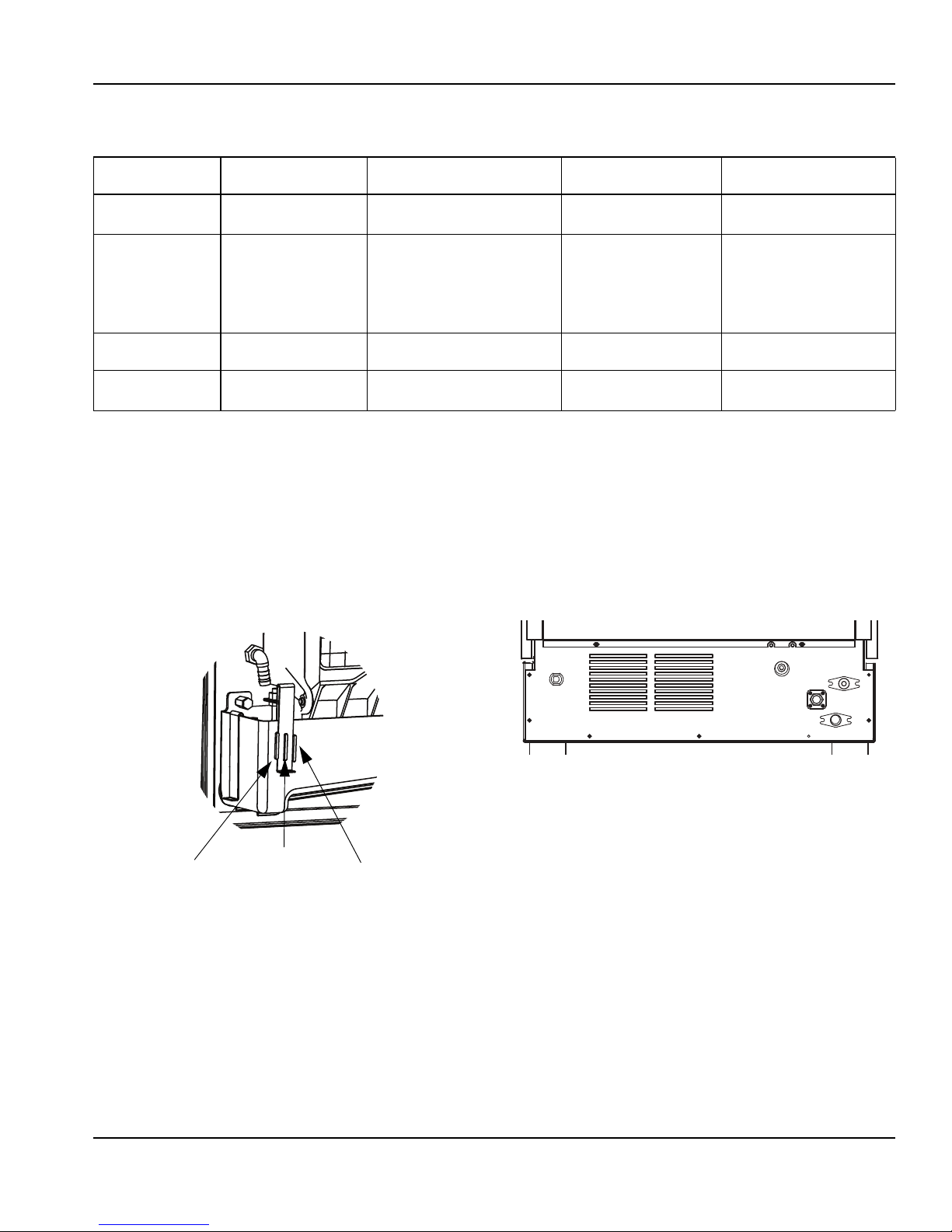
ICE THICKNESS ADJUSTMENT
The ice thickness can be adjusted to three levels.
1. Pull forward on the bottom of the bracket until clear
of the tab.
2. Slide the bracket over the desired tab and release.
• The center position is the normal factory setting.
• To increase bridge thickness, raise the water level.
• To decrease bridge thickness, lower the water level.
Ice Machine
Fitting
3/8" Female Pipe
Thread
3/8" Female Pipe
Thread
U310 Only
1/2" Female Pipe
Thread
Tubing Size Up to Ice
Machine Fitting
3/8" (9.5 mm) minimum
inside diameter
3/8" (9.5 mm) minimum
inside diameter
U310 Only
1/2" (12.7 mm)
minimum inside diameter
1/2" (12.7 mm) minimum
Thread
inside diameter
1/2" (12.7 mm) minimum
Thread
inside diameter
WATER/DRAIN CONNECTIONS
A. Potable Water Inlet
B. Drain
C. Condenser Water Inlet - (Water-cooled Only)
D. Condenser Water Outlet - (Water-cooled Only)
Part Number 040002909 11/13 11
Page 14
Installation Instructions Section 2
!
Warning
Before Starting the Ice Machine
All Manitowoc ice machines are factory-operated and adjusted before shipment. Normally, new installations do not
require any adjustment.
To ensure proper operation, follow the Operational Checks in Section 3 of this manual. Starting the ice machine and
completing the Operational Checks are the responsibilities of the owner/operator.
Adjustments and maintenance procedures outlined in this manual are not covered by the warranty.
Do not operate equipment that has been misused,
abused, neglected, damaged, or altered/modified
from that of original manufactured specifications.
Installation Checklist
Is the ice machine drain vented?
Is the ice machine level?
Are all electrical leads free from contact with
refrigeration lines and moving equipment?
Has all of the internal packing been removed?
Has the owner/operator been instructed
Have all of the electrical and water connections
been made?
regarding maintenance and the use of
Manitowoc Cleaner and Sanitizer?
Has the supply voltage been tested and
checked against the rating on the nameplate?
Is there proper clearance around the ice
machine for air circulation?
Is the ice machine grounded and polarity
correct?
Has the ice machine been installed where
ambient temperatures will remain in the range
of 40° – 110°F (4° – 43°C)?
Has the ice machine been installed where the
incoming water temperature will remain in the
range of 40° – 90°F (4° – 32°C)?
Is there a separate drain for the water-cooled
condenser?
Is there a separate drain for the bin?
Has the owner/operator completed the warranty
registration card?
Has the ice machine and bin been sanitized?
Has the On/Off button been pressed?
12
Part Number 040002909 11/13
Page 15
Section 3
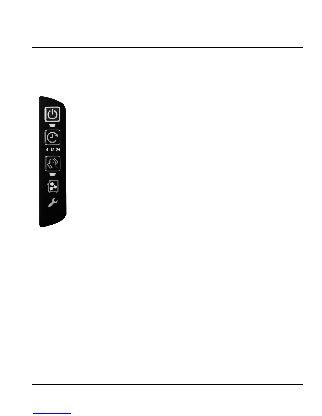
On/Off - Blue = Machine On
Off = Machine Is Off
Delay - Blue = Delay Mode On
Off = Delay Mode Is Off
Clean - Yellow = Clean Cycle On
Off = Cleaning is Off
Bin Full - Blue = Bin Is Full
Off = Bin Is Not Full
Service - Red = Needs Service
Off = Doesn’t Need Service
Operation
Touch Pad Features
The touch pad offers a series of pressure sensitive
buttons to control ice machine operation and provide
operational status.
ON/OFF
The On/Off Button is used to start and stop ice making.
The blue light indicates whether the ice machine is in Ice
Making (light on) or Off (light off).
NOTE: If ice is on the evaporator (during the freeze or
harvest cycle) and the On/Off button is pressed; the next
cycle will have a thick slab of ice. Press the On/Off
button and allow the ice to melt off the evaporator, then
start a new freeze cycle.
DELAY
Pressing the Delay button will start a delay period. The
ice machine will finish the freeze and harvest cycle and
then start the delay period.
• Pressing the button once will start a 4 hour delay
period.
• Pressing the button twice will start a 12 hour delay
period.
• Pressing the button three times will start a 24 hour
delay period.
• Pressing the button four times will cancel the delay
periods.
NOTE: The delay period will be canceled if power is
interrupted to the ice machine. When power is restored,
the ice machine will start an ice making cycle.
CLEAN
Pressing the Clean button for 3 seconds will start a clean
cycle. After the clean cycle is complete, the ice machine
will automatically start an ice making cycle.
• Pressing the Clean button again within 45 seconds of
the clean cycle starting will abort the clean cycle.
• Pressing the On/Off button anytime during the Clean
cycle will de-energize the On/Off LED and the ice
machine will stop after the Clean cycle is complete.
• Pressing the Clean button will pause the Clean cycle.
The On/Off and Clean lights will flash on/off to
indicate pause mode. Pressing the Clean button
again will continue the Clean cycle from the point of
interruption.
NOTE: Opening the ice damper in the clean cycle for 2
seconds will pause the clean cycle. Opening the ice
damper for 30 seconds will cancel the clean cycle.
Part Number 040002909 11/13 13
BIN FULL
The Bin Full light energizes when the bin is full or is deenergized if the bin is not full.
SERVICE
The service light indicates the machine needs attention.
• Refer to Section 5 for more information if this light is
energized.
Page 16

Operation Section 3
Ice Making Sequence of Operation
NOTE: The On/Off button must be depressed and the
ice damper must be closed before the ice machine will
start.
Water Purge Cycle
The ice machine purges any remaining water from the
water trough down the drain.
Freeze Cycle
Prechill - The refrigeration system chills the evaporator
before water flow over the evaporator starts. The water
inlet valve energizes during the pre-chill and remains on
until the ice thickness float switch is satisfied.
Freeze - Water flowing across the evaporator freezes
and builds ice on the evaporator. After a sheet of ice has
formed, the harvest float switch signals the control board
to start a harvest cycle.
Harvest Cycle
Any remaining water is purged down the drain as
refrigerant gas warms the evaporator. When the
evaporator warms, the sheet of cubes slides off the
evaporator and into the storage bin. If all cubes fall clear
of the ice damper the ice machine starts another freeze
cycle.
Full Bin Cycle
If the ice damper is held open by ice cubes the ice
machine shuts off. When the ice damper closes the ice
machine starts a new cycle at the water purge.
Control Board Timers
The control board has the following non-adjustable
timers:
SAFETY LIMITS
Safety limits are stored and indicated by the control
board. The number of cycles required to stop the ice
machine varies for each safety limit.
Safety limits can be reset by pressing the On/Off button
and starting a new ice making cycle.
A safety limit is indicated by a flashing Service Light on
the touch pad. Refer to Section 5 if you receive a safety
limit indication.
• Safety Limit 1 - If the freeze time reaches 60 minutes,
the control board automatically initiates a harvest
cycle. If 6 consecutive 60-minute freeze cycles occur,
the ice machine stops.
• Safety Limit 2 - If the harvest time reaches 3.5
minutes, the control board automatically returns the
ice machine to the freeze cycle. If 500 consecutive
3.5 minute harvest cycles occur, the ice machine
stops.
• Safety Limit 3 - If the freeze time reaches 4 minutes
and water is not sensed, the ice machine stops and
initiates a 30 minute delay period. The ice machine
will automatically restart at the end of the 30 minute
delay period. If 100 consecutive failures occur the ice
machine stops.
• The ice machine is locked into the freeze cycle for 6
minutes before a harvest cycle can be initiated.
• The maximum freeze time is 60 minutes at which
time the control board automatically initiates a
harvest sequence.
• The maximum harvest time is 3.5 minutes. The
control board automatically initiates a freeze
sequence when these times are exceeded.
14
Part Number 040002909 11/13
Page 17

Section 4
!
Caution
!
Caution
!
Warning
!
Caution
Maintenance
Interior Cleaning and Sanitizing
GENERAL
Clean and sanitize the ice machine every six months for
efficient operation. If the ice machine requires more
frequent cleaning and sanitizing, consult a qualified
service company to test the water quality and
recommend appropriate water treatment.
The ice machine must be taken apart for cleaning and
sanitizing.
Use only Manitowoc approved Ice Machine Cleaner
(part number 94-0546-3) and Sanitizer (part
number 94-0565-3). Using a non Manitowoc
cleaner or sanitizer may result in bodily harm and/or
cause damage to the ice machine that is not
covered under the warranty. Do not use cleaner or
sanitizer quantities that exceed the amounts listed
in this manual. It is a violation of Federal law to use
these solutions in a manner inconsistent with their
labeling. Read and understand all labels printed on
bottles before use.
Step 1 Press the On/Off button after ice falls from the
evaporator at the end of a Harvest cycle. Or, press the
On/Off button and allow the ice to melt off the
evaporator.
Never use anything to force ice from the evaporator.
Damage may result.
Step 2 Remove all ice from the bin.
.
Wear rubber gloves and safety goggles (and/or face
shield) when handling Ice Machine Cleaner or
Sanitizer.
Do not mix Ice Machine Cleaner and Sanitizer
solutions together. It is a violation of Federal law to
use these solutions in a manner inconsistent with
their labeling.
CLEANING AND SANITIZING PROCEDURE
Ice machine cleaner is used to remove lime scale and
mineral deposits. Ice machine sanitizer disinfects and
removes algae and slime.
Control Operation
Pressing and holding the clean button for 3 seconds
starts the clean cycle. The Clean & On/Off lights
energize indicating the clean cycle has started and ice
making will automatically start when the Clean cycle is
complete.
• Setting the ice machine to stop after the clean
cycle: Press the On/Off button. The On/Off light will
de-energize indicating the ice machine will stop after
the clean cycle.
• Pausing the cleaning cycle: Press the Clean
button. The clean light will flash indicating the clean
cycle has paused. Pressing the Clean button again
will restart the clean cycle.
NOTE: If the ice damper is open for 2 seconds the clean
cycle will pause - If the damper is open for 30 seconds
the clean cycle will be canceled.
Step 3 To start a cleaning cycle, press the Clean
button. Water will flow through the water dump valve and
down the drain. Wait until the water trough refills, then
add the proper amount of ice machine cleaner to the
water trough.
Model Amount of Cleaner
U0140 2 ounces (60 ml)
U0190 5 ounces (150 ml)
U0240 5 ounces (150 ml)
U0310 5 ounces (150 ml)
Wait until the clean cycle is complete (approximately 22
minutes) then press the On/Off button and disconnect
power and water supplies to the ice machine.
Step 4 Remove parts for cleaning.
Refer to the proper parts removal for your machine.
Continue with step 6 when the parts have been
removed.
Part Number 040002909 11/13 15
Page 18

Maintenance Section 4
Step 5 Mix a solution of cleaner and warm water.
Depending on the amount of mineral buildup, a larger
quantity of solution may be required. Use the ratio in the
table below to mix enough solution to thoroughly clean
all parts.
Solution Type Water Mixed with
Cleaner 1 gal. (4 l) 16 oz (500 ml) cleaner
Use half of the cleaner/water solution to clean all
components. The cleaner solution will foam when it
contacts lime scale and mineral deposits; once the
foaming stops use a soft bristle brush, sponge or cloth
(not a wire brush) to carefully clean the parts. Soak the
parts for 5 minutes (15 – 20 minutes for heavily scaled
parts). Rinse all components with clean water.
Step 6 While components are soaking, use half of the
cleaner/water solution to clean all foodzone surfaces of
the ice machine and bin. Use a nylon brush or cloth to
thoroughly clean the following ice machine areas:
• Evaporator plastic parts – including top, bottom and
sides
• Bin bottom, sides and top
Rinse all areas thoroughly with clean water.
Step 7 Mix a solution of sanitizer and warm water.
Step 8 Use half of the sanitizer/water solution to
sanitize all foodzone surfaces of the ice machine and
bin. Use a spray bottle to liberally apply the solution.
When sanitizing, pay particular attention to the following
areas:
• Evaporator plastic parts - including top, bottom and
sides
• Bin bottom, sides and top
Do not rinse the sanitized areas.
Step 9 Apply food grade lubricant to all o-rings, then
replace all removed components. Wait 10 minutes and
then reapply power and water to the ice machine
Step 10 Press the Clean button. Water will flow through
the water dump valve and down the drain. Wait until the
water trough refills, then add the proper amount of ice
machine sanitizer to the water trough.
Model Amount of Sanitizer
U0140 1 ounces (30 ml)
U0190 2 ounces (60 ml)
U0240 2 ounces (60 ml)
U0310 2 ounces (60 ml)
Wait until the sanitize cycle is complete (approximately
22 minutes) then press the Ice button to start ice making.
Solution Type Water Mixed With
Sanitizer 3 gal. (12 l) 2 oz (60 ml) sanitizer
Use half of the sanitizer/water solution to sanitize all
removed components. Use a spray bottle to liberally
apply the solution to all surfaces of the removed parts or
soak the removed parts in the sanitizer/water solution.
Do not rinse parts after sanitizing.
16
Part Number 040002909 11/13
Page 19

Section 4 Maintenance
Important
!
Warning
ICE THICKNESS FLOAT
SWITCH & BRACKET
WIRE CONNECTORS ARE LOCATED BEHIND BULKHEAD - PULL
THROUGH GROMMET TO DISCONNECT
HARVEST FLOAT SWITCH & BRACKET
DISCONNECT WIRES
FOR COMPLETE
REMOVAL
REMOVE PARTS FOR CLEANING
Disconnect electric power to the ice machine at the
electric switch box before proceeding.
A. Remove the Ice Thickness and Harvest Float
Switch
• Pull forward on the bottom of the bracket until clear of
the tab, then slide bracket upward to remove the
bracket and float switch as an assembly.
NOTE: At this point, the float switch can easily be
cleaned. If complete removal is desired follow the wires
to the bulkhead grommet (exit point) in the back wall.
Pull the wire connector through the bulkhead grommet,
then disconnect the wire leads from the connector.
Reversing the mounting location of the ice thickness and
the harvest floats will result in a safety limit 3 failure.
• The ice thickness float must be mounted to the front
of the water trough and the electrical connection
must be in the top bulkhead grommet.
• The harvest float must be mounted to the side of the
water trough and the electrical connection must be in
the bottom bulkhead grommet.
• The wire connectors for each float are different and
will not allow incorrect electrical bulkhead
connection.
Part Number 040002909 11/13 17
Harvest or Ice Thickness Float Switch Removal
Page 20

Maintenance Section 4
UPPER THUMBSCREW
LOWER THUMBSCREW
2. SUPPORT ICE DAMPER THEN
SLIDE RIGHT SIDE FORWARD TO REMOVE
1. REMOVE THUMBSCREW
1. REMOVE THUMBSCREWS
2. PULL DISTRIBUTION TUBE
FORWARD TO REMOVE
B. Remove the Water Trough
• Remove the upper thumbscrew.
• While supporting the water trough remove the
thumbscrew from beneath the water trough.
• Remove the water trough from the bin area.
C. Remove the Ice Damper
• Remove thumbscrew from bin switch cover.
• Support ice damper and then pull bin switch cover
and ice damper forward to remove.
D. Remove the Water Distribution Tube
• Distribution tube thumbscrews are retained to
prevent loss. Loosen thumbscrews but do not pull
thumbscrews out of distribution tube.
• Loosen the two outer screws and pull forward on the
distribution tube to release.
18
Water Distribution Tube Removal
Part Number 040002909 11/13
Page 21

Section 4 Maintenance
!
Caution
!
Warning
Preventative Maintenance Cleaning
This cleaning procedure can be performed between the
bi-annual cleaning and sanitizing cycles. This procedure
does not require removing the ice from the bin.
Step 1 Press the On/Off button after ice falls from the
evaporator at the end of a Harvest cycle. Or, press the
On/Off button and allow the ice to melt off the
evaporator.
Never use anything to force ice from the evaporator.
Damage may result.
.
Wear rubber gloves and safety goggles (and/or face
shield) when handling Ice Machine Cleaner or
Sanitizer.
Step 2 To start a cleaning cycle, press the Clean
button. Water will flow through the water dump valve and
down the drain. Wait until the water trough refills, then
add the proper amount of ice machine cleaner to the
water trough.
Ice Machine Inspection
Check all water fittings and lines for leaks. Also, make
sure the refrigeration tubing is not rubbing or vibrating
against other tubing, panels, etc.
Do not put anything (boxes, etc.) in front of the ice
machine. There must be adequate airflow through and
around the ice machine to maximize ice production and
ensure long component life.
Exterior Cleaning
Clean the area around the ice machine as often as
necessary to maintain cleanliness and efficient
operation.
Sponge any dust and dirt off the outside of the ice
machine with mild soap and water. Wipe dry with a
clean, soft cloth.
Cleanup any fallen ice or water spills as they occur.
Model Amount of Cleaner
U0140 2 ounce (60 ml)
U0190 5 ounces (150 ml)
U0240 5 ounces (150 ml)
U0310 5 ounces (150 ml)
Wait until the clean cycle is complete (approximately 22
minutes) then press the On/Off button.
Part Number 040002909 11/13 19
Page 22

Maintenance Section 4
!
Warning
!
Warning
Cleaning the Condenser
GENERAL
Disconnect electric power to the ice machine head
section and the remote condensing unit at the
electric service switches before cleaning the
condenser.
A dirty condenser restricts airflow, resulting in
excessively high operating temperatures. This reduces
ice production and shortens component life.
• Clean the condenser at least every six months.
The condenser fins are sharp. Use care when
cleaning them.
• Shine a flashlight through the condenser to check for
dirt between the fins.
• Blow compressed air or rinse with water from the
inside out (opposite direction of airflow).
Removal from Service/Winterization
1. Clean and sanitize the ice machine.
2. Press the On/Off button to turn off the ice machine.
3. Turn off the water supply, disconnect and drain the
incoming ice-making water line at the rear of the ice
machine and drain the water trough.
4. Energize the ice machine, wait one minute for the
water inlet valve to open and blow compressed air in
both the incoming water and the drain openings in
the rear of the ice machine to remove all water.
5. Press the On/Off button and disconnect the electric
power at the circuit breaker or the electric service
switch.
6. Fill spray bottle with sanitizer and spray all interior
food zone surfaces. Do not rinse and allow to air dry.
7. Replace all panels.
• If dirt still remains call a service agent to clean the
condenser.
20
Part Number 040002909 11/13
Page 23

Section 5
Customer Support
Checklist
If a problem arises during operation of your ice machine, follow the checklist below before calling service. Routine
adjustments and maintenance procedures are not covered by the warranty.
Problem Possible Cause To Correct
Ice machine does not operate. No electrical power to the ice machine. Replace the fuse/reset the breaker/turn on
the main switch/plug power cord into
receptacle.
Ice machine needs to be turned on. Press the On/Off button to start ice
making.
Damper in open position (down). Damper must be in upright position and
capable of swinging freely.
Ice machine stops, and can be
restarted by turning the ice machine
OFF and then ON.
Ice sheet is thick Water trough level is too high. Adjust ice thickness float.
Ice machine does not release ice or
is slow to harvest.
Ice machine does not cycle into
harvest mode.
Ice quality is poor
(soft or not clear).
Safety limit feature stopping the ice machine. Refer to “Safety Limit Feature” on the next
page.
Power button was turned off/on during
freeze cycle and ice remained on
evaporator.
Ice damper was opened then closed in the
harvest cycle before the ice released.
Ice machine is dirty. Clean and sanitize the ice machine.
Ice machine is not level. Level the ice machine.
Low air temperature around ice machine
(air-cooled models).
Water regulating valve leaks in harvest
mode (water-cooled models).
The six-minute freeze time lock-in has not
expired yet.
Harvest float switch is dirty. Clean and sanitize the ice machine.
Harvest float switch wire is disconnected. Connect the wire.
Harvest float switch is out of adjustment. Adjust the harvest float switch.
Uneven ice fill (thin at top of evaporator). See “Shallow or Incomplete Cubes” on the
Poor incoming water quality. Contact a qualified service company to
Water filtration is poor. Replace the filter.
Ice machine is dirty. Clean and sanitize the ice machine.
Water softener is working improperly
(if applicable).
Allow ice to thaw and release from
evaporator, then restart.
Allow ice to thaw and release from
evaporator, then restart.
Air temperature must be at least 40°F
(4°C).
Replace water regulating valve.
Wait for freeze lock-in to expire.
next page.
test the quality of the incoming water and
make appropriate filter recommendations.
Repair the water softener.
Part Number 040002909 11/13 21
Continued on next page...
Page 24

Customer Support Section 5
Problem Possible Cause To Correct
Ice machine produces shallow or
incomplete cubes, or the ice fill
pattern on the evaporator is
incomplete.
Low ice capacity. The condenser is dirty. Clean the condenser.
Ice thickness switch is out of adjustment. Adjust the ice thickness switch.
Water trough level is too high or too low. Check the water level.
Water filtration is poor. Replace the filter.
Hot incoming water. Connect the ice machine to a cold water
supply.
Incorrect incoming water pressure. Water pressure must be 20-80 psi (137.9 -
551.5 kPa).
Ice machine is not level. Level the ice machine.
High air temperature around ice machine
(air-cooled models).
Inadequate clearance around the ice
machine.
Objects stacked around ice machine,
blocking airflow to condenser
(air-cooled models).
Hot incoming water. Connect the ice machine to a cold water
Incorrect incoming water pressure. Water
pressure is too low or water filter is
restricted.
Air temperature must not exceed 110°F
(43°C).
Provide adequate clearance.
Remove items blocking airflow.
supply.
Water pressure must be 20-80 psi (137.9 -
551.5 kPa). Refer to section 2 for
plumbing requirements. Replace water
filter.
Safety Limit Feature
In addition to the standard safety controls, such as the
high pressure cutout, your Manitowoc ice machine
features built-in safety limits which will stop the ice
machine if conditions arise which could cause a major
component failure.
Before calling for service, re-start the ice machine using
the following procedure:
1. Press the On/Off button and turn off the ice
machine, then press the On/Off button again to start
the ice machine.
A. If the safety limit feature has stopped the ice
machine, it will restart after a short delay.
Proceed to step 2.
B. If the ice machine does not restart, see “Ice
machine does not operate” on the previous
page.
2. Allow the ice machine to run to determine if the
condition is recurring.
A. If the ice machine stops again, the condition has
recurred. Call for service.
B. If the ice machine continues to run, the condition
has corrected itself. Allow the ice machine to
continue running.
22
Part Number 040002909 11/13
Page 25

Section 5 Customer Support
Commercial Ice Machine Warranty
Manitowoc Ice, Inc. (hereinafter referred to as the “COMPANY”) warrants for a period of thirty-six months from the
installation date (except as limited below) that new ice machines manufactured by the COMPANY shall be free of
defects in material or workmanship under normal and proper use and maintenance as specified by the COMPANY
and upon proper installation and start-up in accordance with the instruction manual supplied with the ice machine.
The COMPANY’s warranty hereunder with respect to the compressor shall apply for an additional twenty-four months,
excluding all labor charges, and with respect to the evaporator for an additional twenty-four months, including labor
charges.
The obligation of the COMPANY under this warranty is limited to the repair or replacement of parts, components, or
assemblies that in the opinion of the COMPANY are defective. This warranty is further limited to the cost of parts,
components or assemblies and standard straight time labor charges at the servicing location.
Time and hourly rate schedules, as published from time to time by the COMPANY, apply to all service procedures.
Additional expenses including without limitation, travel time, overtime premium, material cost, accessing or removal of
the ice machine, or shipping are the responsibility of the owner, along with all maintenance, adjustments, cleaning,
and ice purchases. Labor covered under this warranty must be performed by a COMPANY Contracted Service
Representative or a refrigeration service agency as qualified and authorized by the COMPANY’s local Distributor. The
COMPANY’s liability under this warranty shall in no event be greater than the actual purchase price paid by customer
for the ice machine.
The foregoing warranty shall not apply to (1) any part or assembly that has been altered, modified, or changed; (2)
any part or assembly that has been subjected to misuse, abuse, neglect, or accidents; (3) any ice machine that has
been installed and/or maintained inconsistent with the technical instructions provided by the COMPANY; or (4) any ice
machine initially installed more than five years from the serial number production date. This warranty shall not apply if
the Ice Machine’s refrigeration system is modified with a condenser, heat reclaim device, or parts and assemblies
other than those manufactured by the COMPANY, unless the COMPANY approves these modifications for specific
locations in writing.
THIS WARRANTY IS IN LIEU OF ALL OTHER WARRANTIES OR GUARANTEES OF ANY KIND, EXPRESSED
OR IMPLIED, INCLUDING ANY IMPLIED WARRANTY OF MERCHANTABILITY OR FITNESS FOR A
PARTICULAR PURPOSE. In no event shall the COMPANY be liable for any special, indirect, incidental or
consequential damages. Upon the expiration of the warranty period, the COMPANY’s liability under this warranty shall
terminate. The foregoing warranty shall constitute the sole liability of the COMPANY and the exclusive remedy of the
customer or user.
To secure prompt and continuing warranty service, the warranty registration card must be completed and sent to the
COMPANY within five (5) days from the installation date.
Complete the following and retain for your record:
Distributor/Dealer ______________________________________________________________________________
Model Number ________________________________ Serial Number __________________________________
Installation Date _______________________________________________________________________________
MANITOWOC ICE
2110 So. 26th St., P.O. Box 1720, Manitowoc, WI 54221-1720
Telephone: 920-682-0161 • Fax: 920-683-7585
Web Site - www.manitowocice.com
Form 80-0375-3 Rev. 01-02
Part Number 040002909 11/13 23
Page 26

Customer Support Section 5
Residential Ice Machine Limited Warranty
WHAT DOES THIS LIMITED WARRANTY COVER?
Subject to the exclusions and limitations below, Manitowoc
Foodservice (“Manitowoc”) warrants to the original consumer
that any new ice machine manufactured by Manitowoc (the
“Product”) shall be free of defects in material or workmanship
for the warranty period outlined below under normal use and
maintenance, and upon proper installation and start-up in
accordance with the instruction manual supplied with the
Product.
HOW LONG DOES THIS LIMITED WARRANTY LAST?
Product Covered Warranty Period
Ice Machine Twelve (12) months
from the sale date
WHO IS COVERED BY THIS LIMITED WARRANTY?
This limited warranty only applies to the original consumer of
the Product and is not transferable.
WHAT ARE MANITOWOC ICE’S OBLIGATIONS UNDER
THIS LIMITED WARRANTY?
If a defect arises and Manitowoc receives a valid warranty
claim prior to the expiration of the warranty period, Manitowoc
shall, at its option: (1) repair the Product at Manitowoc’s cost,
including standard straight time labor charges, (2) replace the
Product with one that is new or at least as functionally
equivalent as the original, or (3) refund the purchase price for
the Product. Replacement parts are warranted for 90 days or
the balance of the original warranty period, whichever is
longer. The foregoing constitutes Manitowoc’s sole obligation
and the consumer’s exclusive remedy for any breach of this
limited warranty. Manitowoc’s liability under this limited
warranty is limited to the purchase price of Product. Additional
expenses including, without limitation, service travel time,
overtime or premium labor charges, accessing or removing
the Product, or shipping are the responsibility of the
consumer.
WHAT IS NOT COVERED?
This limited warranty does not cover, and you are solely
responsible for the costs of: (1) periodic or routine
maintenance, (2) repair or replacement of the Product or parts
due to normal wear and tear, (3) defects or damage to the
Product or parts resulting from misuse, abuse, neglect, or
accidents, (4) defects or damage to the Product or parts
resulting from improper or unauthorized alterations,
modifications, or changes; and (5) defects or damage to any
Product that has not been installed and/or maintained in
accordance with the instruction manual or technical
instructions provided by Manitowoc. To the extent that
warranty exclusions are not permitted under some state laws,
these exclusions may not apply to you.
EXCEPT AS STATED IN THE FOLLOWING SENTENCE, THIS LIMITED
WARRANTY IS THE SOLE AND EXCLUSIVE WARRANTY OF
MANITOWOC WITH REGARD TO THE PRODUCT. ALL IMPLIED
ARRANTIES ARE STRICTLY LIMITED TO THE DURATION OF THE
W
LIMITED WARRANTY APPLICABLE TO THE PRODUCTS AS STATED
ABOVE, INCLUDING BUT NOT LIMITED TO, ANY WARRANTY OF
ERCHANTABILITY OR OF FITNESS FOR A PARTICULAR
M
PURPOSE.
Some states do not allow limitations on how long an implied
warranty lasts, so the above limitation may not apply to you.
IN NO EVENT SHALL MANITOWOC OR ANY OF ITS AFFILIATES BE
IABLE TO THE CONSUMER OR ANY OTHER PERSON FOR ANY
L
INCIDENTAL, CONSEQUENTIAL OR SPECIAL DAMAGES OF ANY
KIND (INCLUDING, WITHOUT LIMITATION, LOSS PROFITS,
EVENUE OR BUSINESS) ARISING FROM OR IN ANY MANNER
R
CONNECTED WITH THE PRODUCT, ANY BREACH OF THIS LIMITED
WARRANTY, OR ANY OTHER CAUSE WHATSOEVER, WHETHER
ASED ON CONTRACT, TORT OR ANY OTHER THEORY OF
B
LIABILITY.
Some states do not allow the exclusion or limitation of
incidental or consequential damages, so the above limitation
or exclusion may not apply to you.
HOW TO OBTAIN WARRANTY SERVICE
To obtain warranty service or information regarding your
Product, please contact us at:
MANITOWOC FOODSERVICE
2110 So. 26th St.
P.O. Box 1720,
Manitowoc, WI 54221-1720
Telephone: 920-682-0161 Fax: 920-683-7585
www.manitowocice.com
24
HOW STATE LAW APPLIES
This limited warranty gives you specific legal rights, and you
may also have rights that vary from state to state or from one
jurisdiction to another.
REGISTRATION CARD
To secure prompt and continuing warranty service, this
warranty registration card must be completed and sent to
Manitowoc within thirty (30) days from the sale date. Complete
the following registration card and send it to Manitowoc.
Part Number 040002909 11/13
Page 27

Section 1
Informations générales
Numéros de modèles . . . . . . . . . . . . . . . . . . . . . . . . . . . . . . . . . . . . . . . . . . . . . . . . 27
Accessoires . . . . . . . . . . . . . . . . . . . . . . . . . . . . . . . . . . . . . . . . . . . . . . . . . . . . . . . 29
Section 2
Instructions d’installation
Emplacement de la machine à glaçons . . . . . . . . . . . . . . . . . . . . . . . . . . . . . . . . . 31
Chaleur de rejet de la machine à glaçons . . . . . . . . . . . . . . . . . . . . . . . . . . . . . . . 31
Nivellement de la machine à glaçons . . . . . . . . . . . . . . . . . . . . . . . . . . . . . . . . . . 31
Alimentation électrique . . . . . . . . . . . . . . . . . . . . . . . . . . . . . . . . . . . . . . . . . . . . . . 32
Service d’eau/Évacuations . . . . . . . . . . . . . . . . . . . . . . . . . . . . . . . . . . . . . . . . . . . 34
Dimensionnement/Raccordements des conduites d’alimentation
en eau et d’évacuation . . . . . . . . . . . . . . . . . . . . . . . . . . . . . . . . . . . . . . . . . . . . . . 35
Avant la mise en marche de la machine à glaçons . . . . . . . . . . . . . . . . . . . . . . . 36
Liste de vérification de la procédure d’installation . . . . . . . . . . . . . . . . . . . . . . . 36
Table des matières
Roulettes . . . . . . . . . . . . . . . . . . . . . . . . . . . . . . . . . . . . . . . . . . . . . . . . . . . . . . 29
Système de filtration d’eau Arctic Pure . . . . . . . . . . . . . . . . . . . . . . . . . . . . . . . 29
Nettoyant et désinfectant Manitowoc . . . . . . . . . . . . . . . . . . . . . . . . . . . . . . . . 29
Généralité . . . . . . . . . . . . . . . . . . . . . . . . . . . . . . . . . . . . . . . . . . . . . . . . . . . . . 32
Tension . . . . . . . . . . . . . . . . . . . . . . . . . . . . . . . . . . . . . . . . . . . . . . . . . . . . . . . 32
Fusible/Disjoncteur . . . . . . . . . . . . . . . . . . . . . . . . . . . . . . . . . . . . . . . . . . . . . . 32
Courant admissible total de circuit . . . . . . . . . . . . . . . . . . . . . . . . . . . . . . . . . . 32
Disjoncteur de fuite de terre . . . . . . . . . . . . . . . . . . . . . . . . . . . . . . . . . . . . . . . 32
Caractéristiques électriques . . . . . . . . . . . . . . . . . . . . . . . . . . . . . . . . . . . . . . . 33
Alimentation en eau . . . . . . . . . . . . . . . . . . . . . . . . . . . . . . . . . . . . . . . . . . . . . 34
Lignes d’arrivée d’eau . . . . . . . . . . . . . . . . . . . . . . . . . . . . . . . . . . . . . . . . . . . . 34
Raccordements d’évacuation . . . . . . . . . . . . . . . . . . . . . . . . . . . . . . . . . . . . . . 34
Applications avec tour de refroidissement . . . . . . . . . . . . . . . . . . . . . . . . . . . . 34
Réglage du niveau d’eau . . . . . . . . . . . . . . . . . . . . . . . . . . . . . . . . . . . . . . . . . 35
Raccords d’évacuation/d’eau . . . . . . . . . . . . . . . . . . . . . . . . . . . . . . . . . . . . . . 35
Section 3
Fonctionnement
Caractéristiques du Panneau de commande . . . . . . . . . . . . . . . . . . . . . . . . . . . . 37
Séquence de fabrication des glaçons . . . . . . . . . . . . . . . . . . . . . . . . . . . . . . . . . . 38
Part Number 040002909 11/13 25
Alimentation . . . . . . . . . . . . . . . . . . . . . . . . . . . . . . . . . . . . . . . . . . . . . . . . . . . 37
Temporisation . . . . . . . . . . . . . . . . . . . . . . . . . . . . . . . . . . . . . . . . . . . . . . . . . . 37
Nettoyage . . . . . . . . . . . . . . . . . . . . . . . . . . . . . . . . . . . . . . . . . . . . . . . . . . . . . 37
Bac plein . . . . . . . . . . . . . . . . . . . . . . . . . . . . . . . . . . . . . . . . . . . . . . . . . . . . . . 37
Service . . . . . . . . . . . . . . . . . . . . . . . . . . . . . . . . . . . . . . . . . . . . . . . . . . . . . . . 37
Limites de sécurité . . . . . . . . . . . . . . . . . . . . . . . . . . . . . . . . . . . . . . . . . . . . . . 38
Page 28

Section 4
Entretien
Section 5
Soutien à la clientèle
Table des matières (suite)
Nettoyage intérieur et désinfection . . . . . . . . . . . . . . . . . . . . . . . . . . . . . . . . . . . . . 39
Généralité . . . . . . . . . . . . . . . . . . . . . . . . . . . . . . . . . . . . . . . . . . . . . . . . . . . . . 39
Procédure de nettoyage et de désinfection . . . . . . . . . . . . . . . . . . . . . . . . . . . . 39
Dépose des pièces pour le nettoyage . . . . . . . . . . . . . . . . . . . . . . . . . . . . . . . . 41
Nettoyage périodique d’entretien . . . . . . . . . . . . . . . . . . . . . . . . . . . . . . . . . . . . . . 43
Inspection de la machine à glaçons . . . . . . . . . . . . . . . . . . . . . . . . . . . . . . . . . . . . 43
Nettoyage extérieur . . . . . . . . . . . . . . . . . . . . . . . . . . . . . . . . . . . . . . . . . . . . . . . . . 43
Nettoyage du condenseur . . . . . . . . . . . . . . . . . . . . . . . . . . . . . . . . . . . . . . . . . . . . 44
Généralité . . . . . . . . . . . . . . . . . . . . . . . . . . . . . . . . . . . . . . . . . . . . . . . . . . . . . 44
Mise hors service/Hivérisation . . . . . . . . . . . . . . . . . . . . . . . . . . . . . . . . . . . . . . . . 44
Liste de vérification . . . . . . . . . . . . . . . . . . . . . . . . . . . . . . . . . . . . . . . . . . . . . . . . . 45
Fonction de limite de sécurité . . . . . . . . . . . . . . . . . . . . . . . . . . . . . . . . . . . . . . . . . 46
Garantie commerciale de la machine à glaçons . . . . . . . . . . . . . . . . . . . . . . . . . . 47
Garantie limitée de la machine à glaçons résidentielle . . . . . . . . . . . . . . . . . . . . 48
26 Part Number 040002909 11/13
Page 29

Section 1
! Advertissement
!
Attention
Important
!
Advertissement
! Advertissement
! Advertissement
Informations générales
Numéros de modèles
Le présent manuel s’applique aux modèles suivants :
Autonome
Refroidi à l’air
UD0140A UD0140W
UD0140AE --
UY0140A UY0140W
UY0140AE --
UR0140A --
UR0140AE --
UD0190A --
UD0190AE --
UY0190A --
UY0190AE --
UR0190A --
UR0190AE --
UD0240A UD0240W
UD0240AE UD0240WE
UY0240A UY0240W
UY0240AE UY0240WE
UR0240A --
UR0240AE --
UD0310A UD0310W
UD0310AE --
UY0310A UY0310W
UY0310AE --
UR0310A UR0310W
UR0310AE --
Lisez ces informations avant de procéder :
Autonome
Refroidi à l’eau
L’installation, le soin et l’entretien adéquats sont
essentiels pour une performance maximale et un
fonctionnement sans problème de votre
équipement. Visitez notre site Web à
www.manitowogfsg.com pour obtenir les
renseignements sur les mises à jour des manuels,
les traductions ainsi que les coordonnées des
agents de service dans votre localité.
Les ajustements de routine et les procédures
d’entretien décrits dans ce manuel ne sont pas
couverts par la garantie.
Lisez attentivement le présent manuel avant
l’utilisation, l’installation ou l’entretien sur
l’équipement. Le défaut de suivre les instructions
dans ce manuel peut provoquer des dommages,
des blessures ou la mort.
N’utilisez pas d’appareils et accessoires électriques
autres que ceux fournis par Manitowoc pour votre
modèle de machine à glaçons.
Ne faites pas fonctionner un équipement qui a été
mal utilisé, abusé, négligé, endommagé ou dont les
spécifications originales de fabrication ont été
altérées/modifiées. Cet appareil ne doit pas être
utilisé par des personnes (enfants y compris) ayant
des capacités physiques, sensorielles ou mentales
diminuées, ou ayant un manque d’expérience et de
connaissance, à moins que celles-ci n’aient reçu
une formation sur l’utilisation de l’appareil par une
personne responsable de leur sécurité. Ne pas
laisser les enfants jouer avec l’appareil.
Part Number 040002909 11/13 27
Deux personnes ou plus, ou un appareil de levage
sont nécessaires pour soulever cet appareil.
Page 30

Informations générales Section 1
!
Advertissement
!
Advertissement
!
Advertissement
! Advertissement
! Advertissement
! Advertissement
!
Advertissement
!
Advertissement
!
Advertissement
!
Advertissement
! Advertissement
! Advertissement
Cet équipement comporte une alimentation
électrique haute tension ainsi qu’une charge de
liquide frigorigène. L’installation et les réparations
doivent être effectuées par des techniciens formés
qui sont connaissent les dangers liés à une
alimentation électrique haute tension et au liquide
frigorigène sous pression. Le technicien doit être
également certifié dans le secteur de la
manipulation de liquides frigorigènes et les
procédures d’entretien. Toutes les procédures de
verrouillage et étiquetage doivent être observées
lors de tout travail sur cet équipement.
Ne pas endommager le circuit de réfrigération lors
de l’installation, de l’entretien ou de la réparation de
l’appareil.
Tous les couvercles et panneaux d’accès doivent
être en place et correctement fixés avant d’utiliser
cet équipement.
Le propriétaire de cet équipement est responsable
d’évaluer les risques pour prévoir un équipement de
protection personnelle afin d’assurer une protection
adéquate pendant les procédures d’entretien.
Deux personnes ou plus sont nécessaires pour
déplacer cet équipement afin d’empêcher qu’il
bascule.
Seul le personnel formé et qualifié conscient des
risques associés au frigorigène sous pression, aux
décharges électriques, aux levages et
déplacements inappropriés doit installer, entretenir
ou réparer cet équipement.
Lisez attentivement le présent manuel avant
l’utilisation, l’installation ou l’entretien sur
l’équipement.
Ne pas obstruer les ouvertures ni les orifices de la
machine.
Ne stockez pas de l’essence ou autres vapeurs ou
liquides inflammables à proximité de cet ou de tout
autre appareil.
Ne nettoyez pas avec un jet d’eau.
28
Tous les couvercles et panneaux d’accès doivent
être en place et correctement fixés avant d’utiliser
cet équipement.
Ne pas endommager le circuit de réfrigération lors
de l’installation, de l’entretien ou de la réparation de
l’appareil.
Part Number 040002909 11/13
Page 31

Section 1 Informations générales
Accessoires
Communiquez avec votre distributeur Manitowoc pour
obtenir ces accessoires optionnels :
ROULETTES
Pattes standard de rechange.
SYSTÈME DE FILTRATION D’EAU ARCTIC PURE
Conçu spécifiquement pour les machines à glaçons
Manitowoc, le filtre à eau Arctic Pure est une méthode
efficace, fiable et abordable pour empêcher la formation
de tartre, filtrer les sédiments et éliminer le goût et
l’odeur du chlore.
NETTOYANT ET DÉSINFECTANT MANITOWOC
Le nettoyant et le désinfectant pour machine à glaçons
Manitowoc sont offerts en format bouteille pratique de
473 ml (16 oz) et de 3,78 l (1 gallon). Ces produits sont
les seuls nettoyants et désinfectants approuvés pour
usage avec les produits Manitowoc.
Réf. Nettoyant Réf. Désinfectant
16 oz 94-0456-3 16 oz 94-0565-3
1 gallon 94-0580-3 1 gallon 94-0581-3
LuminIce™
L’inhibiteur de croissance LuminIce™ fait circuler l’air
dans la zone alimentaire de la machine à glaçons sur
une ampoule UV. Ce procédé entravera la croissance de
micro-organismes communs sur toutes les surfaces
exposées de la zone alimentaire.
• Les ampoules LuminIce™ doivent être remplacées
sur une base annuelle. Même si l’ampoule illuminera
encore après 12 mois, l’efficacité de l’ampoule
diminue au fur et à mesure que les heures de
fonctionnement augmentent. Pour garder une
efficacité maximale, remplacer l’ampoule tous les
12
mois.
Procédure de nettoyage lors d’un bris accidentel de
l’ampoule
La procédure de nettoyage est identique à la procédure
utilisée pour nettoyer la lampe fluorescente compacte
(LFC) ou les tubes fluorescents. Ces lampes contiennent
une petite quantité de mercure scellé dans le tube de verre.
Briser ce type de lampes relâchera du mercure et des
vapeurs de mercure. L’ampoule brisée peut continuer de
relâcher des vapeurs de mercure jusqu’à ce qu’elle soit
nettoyée et enlevée.
Les procédures les plus récentes de l’EPA peuvent être
consultées sur leur site web au www.epa.gov/cfl/
cflcleanup.html.
Part Number 040002909 11/13 29
Page 32

Informations générales Section 1
CETTE PAGE LAISSÉE EN BLANC INTENTIONNELLEMENT
30
Part Number 040002909 11/13
Page 33

Section 2
!
Attention
!
Advertissement
!
Attention
! Advertissement
Instructions d’installation
Emplacement de la machine à glaçons
Le choix de l’emplacement pour la machine à glaçons
doit respecter les critères suivants. Si l’un de ces critères
n’est pas respecté, choisir un autre emplacement.
• L’emplacement doit être à l’intérieur.
• L’emplacement doit être exempt d’agents aéroportés
et de tous autres contaminants.
• La température de l’air doit être d’au moins de 4 °C
(40 °F) sans toutefois excéder 43 °C (110 °F).
• L’emplacement ne doit pas se trouver à proximité
d’appareils générateurs de chaleur ou à la lumière
directe du soleil.
• L’emplacement doit pouvoir supporter le poids de la
machine à glaçons et un bac plein de glaçons.
• L’emplacement doit permettre un dégagement
suffisant pour les raccordements d’eau et
d’évacuation ainsi que les branchements électriques
à l’arrière de la machine à glaçons.
• L’emplacement ne doit pas obstruer la circulation
d’air à travers et autour de la machine à glaçons
(l’entrée et la sortie de la circulation d’air s’effectuent
à l’avant). Consulter le tableau ci-dessous pour
obtenir les conditions d’espace requises.
• L’emplacement ne doit pas être à proximité des
déchets ou de tous autres contaminants.
Autonome
Refroidi à l’air
Haut/Côtés 127 mm (5 po)* 127 mm (5 po)*
Arrière 127 mm (5 po)* 127 mm (5 po)*
Autonome
Refroidi à l’eau
Chaleur de rejet de la machine à glaçons
Série Machine
à glaçons
U140 2400 2900
U190 2200 2600
U240 2400 3400
U310 3800 6000
* B.T.U./Heure
** Étant donné que la chaleur de rejet varie durant le cycle de
fabrication de glaçons, la figure illustrée est une moyenne.
Les machines à glaçons, tout comme tout autre
équipement de réfrigération, rejettent la chaleur par le
condenseur. Il est utile de connaître la quantité de
chaleur rejetée par la machine à glaçons lors du
dimensionnement du matériel de conditionnement d’air
où sont installées les machines à glaçons autonomes
refroidies à l’air.
Deux personnes ou plus, ou un appareil de levage
sont nécessaires pour soulever cet appareil.
Conditionnement d’air** Crête
Chaleur de rejet*
Nivellement de la machine à glaçons
1. Visser les pattes de nivellement sur le dessous de la
machine à glaçons.
2. Visser le pied de chaque patte aussi loin que
possible.
Les pattes doivent être bien serrées pour les
empêcher de se courber.
REMARQUE : La machine à glaçons peut être
encastrée dans une armoire. Il n’y a aucune exigence de
dégagement minimum pour le dessus et les côtés de la
machine à glaçons. Les valeurs indiquées sont
recommandées uniquement pour un fonctionnement et
un entretien efficaces.
La machine à glaçons doit être protégée si elle est
susceptible d’être soumise à des températures
inférieures à 0 °C (32 °F). Toute défaillance due à
une exposition à des températures inférieures à 0°C
n’est pas couverte par la garantie. Vous reporter à la
section 4 «
Part Number 040002909 11/13 31
Mise hors service/Hivérisation ».
3. Déplacer la machine à glaçons à son emplacement
définitif.
Ne pas obstruer les ouvertures ni les orifices de la
machine à glaçons.
4. Mettre de niveau la machine à glaçons en plaçant
un niveau à bulle d’air sur le dessus de la machine à
glaçons. Tourner chaque pied au besoin afin de
mettre de niveau la machine à glaçons dans les
axes de l’avant à l’arrière et de côté à côté.
Page 34

Instructions d’installation Section 2
! Advertissement
!
Attention
! Advertissement
!
Advertissement
Alimentation électrique
GÉNÉRALITÉ
Tout le câblage doit être conforme aux codes
locaux, régionaux et nationaux.
Faire fonctionner l’équipement uniquement sur le
type d’électricité indiqué sur la plaque signalétique.
TENSION
La variation de tension admissible maximale est de +/−
10 % de la tension nominale indiquée sur la plaque de
numéro de modèle/série de la machine à glaçons au
démarrage (lorsque la charge électrique est la plus
haute).
Les machines à glaçons 115/1/60 sont précâblées à
l’usine avec un cordon d’alimentation NEMA 5-15P de
2,44 m (8 pi).
Les machine à glaçons 208-230/1/60 et 230/50/1 sont
précâblées à l’usine avec un cordon d’alimentation de
2,44 m (8 pi), aucune fiche n’est fournie.
FUSIBLE/DISJONCTEUR
Un fusible/disjoncteur séparé doit être fourni pour
chaque machine à glaçons.
La machine à glaçons doit être mise à la terre
conformément aux codes de l’électricité nationaux
et locaux.
COURANT ADMISSIBLE TOTAL DE CIRCUIT
Le courant admissible total de circuit permet de
sélectionner le calibre du câble de l’alimentation
électrique.
La dimension de câble (ou le calibre) dépend également
de l’emplacement, des matériaux utilisés, de la longueur
de la conduite, etc., celle-ci doit donc être déterminée
par un électricien qualifié.
DISJONCTEUR DE FUITE DE TERRE
Une protection par disjoncteur de fuite de terre (GFCI/
GFI) est un système qui coupe le circuit électrique
(l’ouvre) quand il détecte une perte inattendue de
courant, probablement à la terre. Manitowoc ne
recommande pas l’emploi d’un disjoncteur de fuite de
terre avec notre équipement. Si le code requiert l’emploi
d’un disjoncteur de fuite de terre, il convient alors de
respecter le code local. Le circuit doit être spécialisé, de
dimensions correctes et il doit y avoir un disjoncteur de
fuite de terre de panneau. Nous ne recommandons
l’emploi de prises électriques avec disjoncteur de fuite
de terre étant donné qu’elles sont connues pour
provoquer davantage de défaillances parasites
intermittentes que les disjoncteurs de panneau.
Si le cordon d’alimentation est endommagé, ne pas
faire fonctionner l’appareil tant que le cordon n’a pas
été remplacé par un agent de service ou une
personne qualifiée.
32
Part Number 040002909 11/13
Page 35

Section 2 Instructions d’installation
CARACTÉRISTIQUES ÉLECTRIQUES
Machine à
glaçons
U140
U190
U240
U310
Ten sio n
Phase
Cycle
115/1/60 15 5,0 15 5,0
208-230/1/60 15 2,5 -- --
230/1/50 15 2,5 -- -115/1/60 15 6,0 -- --
208-230/1/60 15 2,5 -- --
230/1/50 15 2,5 -- -115/1/60 15 7,0 15 6,0
208-230/1/60 15 4,0 15 3,0
230/1/50 15 4,0 15 3,0
115/1/60 15 10,0 15 10,0
208-230/1/60 15 4,5 15 4,0
230/1/50 15 4,5 -- --
Fusible/Disjoncteur
maximum
Refroidi à l’air Refroidi à l’eau
Intensité de
courant totale
Fusible/Disjoncteur
maximum
Intensité de
courant totale
Part Number 040002909 11/13 33
Page 36

Instructions d’installation Section 2
!
Attention
Important
!
Advertissement
Important
Service d’eau/Évacuations
ALIMENTATION EN EAU
En fonction des conditions d’eau locales, il peut s’avérer
nécessaire de traiter l’eau pour empêcher la formation
de tartre, filtrer les sédiments et améliorer le goût et la
clarté.
La tuyauterie doit être conforme aux codes locaux et
régionaux.
Pour l’installation d’un système de filtration d’eau
Manitowoc, vous référer aux instructions
d’installation fournies avec le système de filtration
pour les raccordements d’arrivée d’eau de
fabrication de glaçons.
Pour la fabrication de glaçons, connecter à une
alimentation en eau potable uniquement.
LIGNES D’ARRIVÉE D’EAU
Suivre ces directives pour l’installation des conduites
d’arrivée d’eau
• Ne pas raccorder la machine à glaçons à une
alimentation en eau chaude. S’assurer que tous les
restricteurs d’eau chaude installés pour les autres
appareils fonctionnent. (clapets de non-retour sur
robinets d’éviers, lave-vaisselle, etc.)
• Si la pression d’eau dépasse la pression
maximale recommandée (80 psig/551,5 kPA), vous
procurer un régulateur de pression d’eau auprès d’un
distributeur Manitowoc.
• Installer un robinet d’arrêt d’eau et un raccord-union
pour les deux conduites d’eau pour la fabrication de
glaçons et du condenseur.
• Isoler les conduites d’arrivée d’eau pour éviter les
problèmes de condensation.
:
RACCORDEMENTS D’ÉVACUATION
Suivre ces directives lors de l’installation des conduites
d’évacuation pour empêcher l’eau d’évacuation de
retourner s’écouler dans la machine à glaçons et dans le
bac de stockage :
• Les conduites d’évacuation doivent comporter une
descente de 2,5 cm par mètre (1,5 pouce par
5
pieds) et ne doivent pas créer de siphons.
• Le siphon de sol doit être suffisamment grand pour
recevoir l’eau provenant de toutes les évacuations.
• Acheminer séparément les conduites d’évacuation
de bac et de condenseur refroidi à l’eau. Les isoler
pour prévenir la condensation.
• Ventiler la conduite d’évacuation de la machine à
glaçons. Ne pas ventiler l’évacuation du condenseur
sur les modèles refroidis à l’eau.
APPLICATIONS AVEC TOUR DE
REFROIDISSEMENT
(Modèles refroidis à l’eau)
Une installation avec tour de refroidissement à eau ne
requiert pas de modification de la machine à glaçons. Le
régulateur d’eau du condenseur continue de contrôler la
pression de refoulement de réfrigération.
Il est nécessaire de connaître la quantité de chaleur
rejetée ainsi que la chute de pression dans le
condenseur et les robinets d’eau (entrée et sortie) lors
de l’utilisation d’une tour de refroidissement sur une
machine à glaçons.
• La température de l’eau arrivant dans le condenseur
ne doit pas dépasser 32 °C (90 °F).
• La quantité d’eau traversant le condenseur ne doit
pas dépasser 19 litres (5
• Prévoir une chute de pression de 48 kPa (7 psi) entre
l’arrivée d’eau du condenseur et la sortie de la
machine à glaçons.
• La température de l’eau arrivant dans le condenseur
ne doit pas dépasser 43 °C (110 °F).
L’État du Massachusetts exige que tous les modèles
refroidis à l’eau soient raccordés uniquement à un
système de tour de refroidissement à boucle
fermée.
gallons) par minute.
34
Part Number 040002909 11/13
Page 37

Section 2 Instructions d’installation
Pont plus
mince
Réglages
par défaut
à l’usine
Pont plus
épais
B
D
C
A
Dimensionnement/Raccordements des conduites d’alimentation en eau et d’évacuation
Emplacement
Arrivée d’eau
pour la fabrication
de glaçons
Arrivée d’eau
de condenseur
Évacuation d’eau
du condenseur
Évacuation
de bac
Température
de l’eau
4 °C (40 °F) Min.
32 °C (90 °F) Max.
4 °C (40 °F) Min.
32 °C (90 °F) Max.
--- --- Filetage femelle de tuyau de
--- --- Filetage femelle de tuyau de
1034,2 kPa (150 psi) Max.
Pression
137,9 kPa (20 psi) Min.
551,5 kPa (80 psi) Max.
137,9 kPa (20 psi) Min.
RÉGLAGE DU NIVEAU D’EAU
Le niveau d’eau peut être réglé à trois niveaux.
1. Tirer vers l’avant au bas du support jusqu’au
dégagement de la languette.
2. Glisser le support sur la languette souhaitée et
relâcher.
• La position du centre est le réglage normal de
l’usine.
d’eau
Raccordement de la
machine à glaçons
Filetage femelle de tuyau de
3/8 po
Filetage femelle de tuyau de
3/8 po
U310 seulement
Filetage femelle de tuyau de
1/2 po
1/2 po
1/2 po
Dimension de tubulure
jusqu’à raccordement
de machine à glaçons
3/8 po diamètre intérieur
minimum
3/8 po diamètre intérieur
minimum
U310 seulement
1/2 po diamètre intérieur
minimum
1/2 po diamètre intérieur
minimum
1/2 po diamètre intérieur
minimum
RACCORDS D’ÉVACUATION/D’EAU
A. Arrivée d’eau potable
B. Drain
C. Arrivée d’eau du condenseur - (Refroidi à l’eau
seulement)
D. Sortie d’eau du condenseur - (Refroidi à l’eau
seulement)
• Pour augmenter l’épaisseur du pont, hausser le
niveau d’eau.
• Pour diminuer l’épaisseur du pont, abaisser le niveau
d’eau.
Part Number 040002909 11/13 35
Page 38

Instructions d’installation Section 2
! Advertissement
Avant la mise en marche de la machine à glaçons
Toutes les machines à glaçons Manitowoc sont mises en route et ajustées en usine avant l’expédition. Normalement,
les nouvelles installations ne requièrent aucun ajustement.
Pour garantir un bon fonctionnement, suivre les Contrôles opérationnels figurant à la Section 3 du présent manuel. La
mise en marche de la machine à glaçons et exécuter les contrôles opérationnels sont la responsabilité du
propriétaire/de l’opérateur.
Les réglages et les procédures de maintenance indiqués dans ce manuel ne sont pas couverts par la garantie.
Ne faites pas fonctionner un équipement qui a été
mal utilisé, abusé, négligé, endommagé ou dont les
spécifications originales de fabrication ont été
altérées/modifiées.
Liste de vérification de la procédure d’installation
La machine à glaçons est-elle de niveau ?
L’emballage interne a-t-il été retiré ?
Tous les raccordements électriques et d’eau
ont-ils été effectués ?
La tension d’alimentation a-t-elle été testée et
vérifiée par rapport à la valeur nominale
indiquée sur la plaque signalétique ?
Y a-t-il un dégagement suffisant autour de la
machine à glaçons pour la circulation d’air ?
La machine a-t-elle été mise à la terre et la
polarité est-elle correcte ?
La machine à glaçons a-t-elle été installée là où
des températures ambiantes resteront dans la
plage de 4 °C à 43 °C (40 °F à 110 °F) ?
Y a-t-il une évacuation séparée pour le bac ?
L’évacuation de la machine à glaçons est-elle
ventilée ?
Tous les fils électriques sont-ils exempts de
contact des lignes de réfrigération et de
l’équipement mobile ?
Le propriétaire/l’utilisateur a-t-il été informé de
l’entretien et de l’utilisation du nettoyant et du
désinfectant Manitowoc ?
Le propriétaire/l’utilisateur a-t-il rempli la carte
de garantie ?
La machine à glaçons et le bac ont-ils été
désinfectés ?
Le bouton d’alimentation est-il réglé à glaçons ?
La machine à glaçons a-t-elle été installée là où
la température d’arrivée d’eau demeurera dans
la plage de 4 °C à 32 °C (40 °F à 90 °F) ?
Y a-t-il une évacuation séparée pour le
condenseur refroidi par eau ?
36
Part Number 040002909 11/13
Page 39

Section 3
Alimentation - Bleu = Machine en marche
Arrêt = Machine en arrêt
Délai - Bleu = Mode temporisation en marche
Arrêt = Mode temporisation en arrêt
Nettoyage - Jaune = Cycle de nettoyage
en marche
Arrêt = Nettoyage en arrêt
Bac plein - Bleu = Le bac est plein
Arrêt = Le bac n’est pas plein
Service - Rouge = Nécessite un service
Arrêt = Ne nécessite pas un service
Fonctionnement
Caractéristiques du Panneau de commande
Le panneau de commande est doté de boutons
sensibles à la pression pour commander la machine à
glaçons et procure aussi l’état de fonctionnement.
ALIMENTATION
Le bouton Alimentation est utilisé pour démarrer et
arrêter la machine à glaçons. Le témoin bleu indique si
la machine à glaçons est en mode de fabrication de
glaçons (témoin allumé) ou en arrêt (témoin éteint).
TEMPORISATION
En appuyant sur le bouton Temporisation, la
temporisation commencera. La machine à glaçons
complétera le cycle de congélation et de récupération
puis commencera la temporisation.
• En appuyant une (1) fois sur le bouton, une
temporisation d’une durée de 4 heures commencera.
• En appuyant deux (2) fois sur le bouton, une
temporisation d’une durée de 12 heures
commencera.
• En appuyant trois (3) fois sur le bouton, une
temporisation d’une durée de 24 heures
commencera.
• En appuyant sur le bouton quatre (4) fois, la
temporisation sera annulée.
• Puissance interruption aux glace usiner vouloir
annulé les retardé époque.
NETTOYAGE
En appuyant sur le bouton Nettoyage pendant 3
secondes, le cycle de nettoyage commencera. Après le
cycle de nettoyage, la machine à glaçons commencera
automatiquement le cycle de fabrication de glaçons.
• En appuyant à nouveau sur le bouton Nettoyage
dans les 45 secondes après le démarrage du cycle
de nettoyage annulera le cycle.
• En appuyant le bouton Alimentation n'importe quand
pendant le cycle de nettoyage éteindra la DEL de
l’alimentation électrique et la machine à glaçons
s’arrêtera lorsque le cycle de nettoyage sera
complété.
En appuyant sur le bouton Nettoyage, le cycle de
nettoyage activera le mode Pause. Le témoin
Alimentation et Nettoyage clignotera pour indiquer le
mode Pause. En appuyant à nouveau sur le bouton
Alimentation, le cycle de nettoyage recommencera là où
il a été interrompu.
BAC PLEIN
Le témoin Bac plein s’allume lorsque le bac est plein ou
s’éteint si le bac n’est pas plein.
SERVICE
Le témoin Service indique que la machine nécessite un
service.
• Vous reporter à la section 5 pour de plus amples
informations si le témoin s’allume.
Part Number 040002909 11/13 37
Page 40

Fonctionnement Section 3
Séquence de fabrication des glaçons
REMARQUE : Le bouton Alimentation doit être enfoncé
et l’amortisseur de glaçons doit être fermé avant que la
machine à glaçons démarre.
Cycle de purge d’eau
La machine à glaçons évacue toute eau restante du bac
à eau par le siphon.
Cycle de congélation
Pré-refroidissement - Le système de réfrigération
refroidit l’évaporateur avant la circulation d’eau audessus de l’évaporateur. Le robinet d’arrivée d’eau est
alimenté pendant le pré-refroidissement et demeure
ainsi jusqu’à ce que l’interrupteur à flotteur de niveau
d’eau soit au bon niveau d’eau.
Congélation - L’eau qui s’écoule sur l’évaporateur gèle
et forme une glace sur celui-ci. Après qu’une couche de
glace soit formée, l’interrupteur à flotteur d’épaisseur de
glace envoie un signal au tableau de commande de
commencer un cycle de récupération.
Cycle de récupération
Toute l’eau restante s’évacue dans le siphon tandis que
le gaz réfrigérant chauffe l’évaporateur. Lorsque
l’évaporateur chauffe, la couche de glaçons glisse de
l’évaporateur vers le bac de stockage. Si tous les
glaçons tombent au-delà de l’amortisseur de glaçons, la
machine à glaçons démarre un autre cycle de
congélation.
Cycle Bac Plein
LIMITES DE SÉCURITÉ
Les limites de sécurité sont mises en mémoire et
indiquées par le tableau de commande au bout de trois
cycles. Le nombre de cycles requis pour arrêter la
machine à glaçons varie pour chaque limite de sécurité.
• Limite de sécurité 1 - Si le temps de congélation
atteint 60 minutes, le tableau de commande lance
automatiquement un cycle de récupération des
glaçons. La machine à glaçons s’arrête après
6
cycles consécutifs de congélation de 60 minutes.
• Limite de sécurité 2 - Si le temps de récupération des
glaçons atteint 3,5 minutes, le tableau de commande
lance automatiquement le cycle de congélation de la
machine à glaçons. La machine à glaçons s’arrête
après 500 cycles consécutifs de récupération de
3,5
minutes.
Une limite de sécurité est indiquée par le clignotement
du témoin Service sur le panneau de commande.
Consulter la section 5 si vous recevez une indication de
limite de sécurité.
Si l’amortisseur de glaçons est maintenu ouvert par la
présence de glaçons, la machine à glaçons s’arrête.
Lorsque l’amortisseur de glaçons se ferme, la machine à
glaçons démarre un nouveau cycle à la purge d’eau.
Temporisateurs de tableau de commande
Le tableau de commande comporte les temporisateurs
non réglables suivants :
• La machine à glaçons est verrouillée dans le cycle
de congélation pendant 6 minutes avant de pouvoir
lancer le cycle de récupération.
• Le temps de congélation maximal est de 60 minutes
après quoi le tableau de commande lance
automatiquement une séquence de récupération des
glaçons.
• Le temps de récupération maximal est de
3,5
minutes. Le tableau de commande lance
automatiquement une séquence de congélation
lorsque ces temps sont dépassés.
38
Part Number 040002909 11/13
Page 41

Section 4
!
Attention
!
Attention
!
Avertissement
!
Attention
Entretien
Nettoyage intérieur et désinfection
GÉNÉRALITÉ
Nettoyer et désinfecter la machine à glaçons tous les six
mois pour un fonctionnement efficace. Si la machine à
glaçons requiert un nettoyage et une désinfection plus
fréquents, consulter une entreprise de service qualifiée
pour tester la qualité de l’eau et recommander un
traitement approprié de l’eau.
La machine à glaçons doit être démontée pour le
nettoyage et la désinfection.
N’utiliser que le nettoyant pour machine à glaçons
(réf. 94-0546-3) et le désinfectant (réf. 94-0565-3)
qui sont approuvés par Manitowoc. L’utilisation de
ces solutions sans tenir compte des instructions
figurant sur leurs étiquettes est une violation de la
loi fédérale. Lire et comprendre toutes les étiquettes
imprimées sur les récipients avant utilisation.
PROCÉDURE DE NETTOYAGE ET DE
DÉSINFECTION
Utiliser le nettoyant pour machine à glaçons pour
éliminer le tartre et les dépôts minéraux. Le désinfectant
pour machine à glaçons désinfecte et élimine les algues
et tout film biologique.
Étape 1 Appuyer sur le bouton Alimentation après la
chute de glace de l’évaporateur à la fin du cycle de
récupération. Ou, appuyer sur le bouton Alimentation et
permettre la fonte de glace de l’évaporateur.
Ne jamais utiliser quoi que ce soit pour forcer la
glace à sortir de l’évaporateur. Ceci pourrait causer
des dommages.
Étape 2 Retirer tous les glaçons du bac.
.
Porter des gants en caoutchouc et des lunettes de
sécurité (et/ou un masque) lors de la manipulation
du nettoyant ou du désinfectant pour machine à
glaçons.
Ne pas mélanger les solutions nettoyantes et
désinfectantes pour machine à glaçons. L’utilisation
de ces solutions sans tenir compte des instructions
figurant sur leurs étiquettes est une violation de la
loi fédérale.
Étape 3 Pour démarrer le cycle de nettoyage, appuyer
sur le bouton Nettoyage. L’eau s’écoulera par le robinet
de vidange d’eau puis dans le drain. Attendre que l’eau
remplisse le bac à eau puis ajouter la bonne quantité de
nettoyant pour machine à glaçons dans le bac à eau.
Modèle Quantité de nettoyant
U0140 60 ml (2 onces)
U0190 150 ml (5 onces)
U0240 150 ml (5 onces)
U0310 150 ml (5 onces)
Attendre que le cycle de nettoyage soit terminé (environ
22
minutes), puis appuyer sur le bouton Alimentation et
couper l’alimentation électrique ainsi que l’alimentation
d’eau à la machine à glaçons.
Étape 4 Retirer les pièces à nettoyer.
Vous référer aux procédures de dépose des pièces qui
correspondent à votre machine à glaçons. Passer à
l’étape 6 une fois les pièces retirées.
Étape 5 Mélanger une solution nettoyante avec de
l’eau chaude. Selon la quantité de dépôt minéral, une
quantité plus importante de solution peut être requise.
Utiliser le ratio dans le tableau ci-dessous pour
mélanger suffisamment de solution pour nettoyer toutes
les pièces.
Part Number 040002909 11/13 39
Type de
solution
Nettoyant 4 l (1 gallon) 500 ml (16 oz) de nettoyant
Utiliser la moitié du mélange nettoyant/eau pour nettoyer
tous les composants. La solution nettoyante mousse
lorsqu’elle est en contact avec du tartre ou des dépôts
Eau Mélangée avec
Page 42

Entretien Section 4
minéraux; lorsque la formation de mousse s’arrête,
utiliser une brosse en nylon à poils souples, une éponge
ou un chiffon (PAS une brosse métallique) pour nettoyer
soigneusement les pièces. Faire tremper les pièces
pendant 5 minutes (15 à 20 minutes pour les pièces
fortement entartrées). Rincer tous les composants avec
de l’eau propre.
Étape 6 Pendant le trempage des composants, utiliser
la moitié de la solution nettoyant/eau pour nettoyer
toutes les surfaces de la zone alimentaire de la machine
à glaçons et du bac. Utiliser une brosse en nylon ou un
chiffon pour nettoyer les zones suivantes de la machine
à glaçons :
• Pièces en plastique de l’évaporateur – y compris les
parties supérieures, inférieures et latérales
• Le bas, les côtés et le dessus du bac
Rincer complètement toutes les zones avec de l’eau
propre.
Étape 7 Mélanger une solution désinfectante avec de
l’eau chaude.
Type de
solution
Désinfectant 12 l (3 gallons) 60 ml (2 oz) de désinfectant
Eau Mélangée avec
ajouter la bonne quantité de désinfectant pour machine
à glaçons dans le bac à eau.
Modèle Quantité de désinfectant
U0140 30 ml (1 onces)
U0190 60 ml (2 onces)
U0240 60 ml (2 onces)
U0310 60 ml (2 onces)
Attendre que le cycle de désinfection soit terminé
(environ 22 minutes), appuyer sur le bouton Glaçons
pour commencer la fabrication de glaçons.
Utiliser la moitié de la solution désinfectant/eau pour
désinfecter tous les composants retirés. Utiliser un
flacon pulvérisateur pour appliquer abondamment la
solution sur toutes les surfaces des pièces retirées ou
faire tremper les pièces retirées dans la solution
désinfectant/eau. Ne pas rincer les pièces après la
désinfection.
Étape 8 Utiliser la moitié de la solution désinfectant/eau
pour désinfecter toutes les surfaces de la zone
alimentaire de la machine à glaçons et du bac. Utiliser
un flacon pulvérisateur pour appliquer abondamment la
solution. Lors de la désinfection, faire particulièrement
attention aux zones suivantes :
• Pièces en plastique de l’évaporateur – y compris les
parties supérieures, inférieures et latérales
• Le bas, les côtés et le dessus du bac
Ne pas rincer les zones désinfectées.
Étape 9 Remettre tous les composants retirés, attendre
10 minutes puis brancher l’alimentation électrique et
ouvrir l’alimentation en eau à la machine à glaçons.
Étape 10 Appuyer sur le bouton Nettoyage. L’eau
s’écoulera par le robinet de vidange d’eau puis dans le
drain. Attendre que l’eau remplisse le bac à eau puis
40
Part Number 040002909 11/13
Page 43

Section 4 Entretien
! Avertissement
INTERRUPTEUR À FLOTTEUR DE NIVEAU
D’EAU ET SUPPORT
LES CONNECTEUR DE FILS SE TROUVENT DERRIÈRE LA
CLOISON - TIRER PAR L’ŒILLET POUR DÉBRANCHER.
INTERRUPTEUR À FLOTTEUR D’ÉPAISSEUR DE GLACE ET SUPPORT
DÉBRANCHER LES FILS
POUR LA DÉPOSE
COMPLÈTE
DÉPOSE DES PIÈCES POUR LE NETTOYAGE
Débrancher l’alimentation électrique de la machine
à glaçons au niveau de la boîte de distribution
électrique avant de commencer.
A. Retrait de la sonde de niveau d’eau et de
l’interrupteur à flotteur.
• Tirer vers l’avant au bas du support jusqu’au
dégagement de la languette puis glisser le support
vers le haut pour retirer ensemble celui-ci et la
sonde. Répéter cette procédure pour retirer
l’interrupteur à flotteur.
REMARQUE : À ce moment, l’interrupteur à flotteur ainsi
que la sonde peuvent être facilement nettoyés. Si une
dépose complète est souhaitée, suivre les fils jusqu’à
l’œillet de la cloison (point de sortie) dans la paroi
arrière. Tirer le connecteur de fils par l’œillet de la
cloison puis débrancher les fils du connecteur.
Dépose de l’interrupteur à flotteur
du niveau d’eau ou de l’interrupteur d’épaisseur
de glace
Part Number 040002909 11/13 41
Page 44

Entretien Section 4
VIS À OREILLE SUPÉRIEURE
VIS À OREILLE INFÉRIEURE
2. SOUTENIR L’AMORTISSEUR DE GLAÇONS
PUIS GLISSER LE CÔTÉ DROIT VERS L’AVANT
POUR RÉALISER LA DÉPOSE
1. RETIRER LA VIS À OREILLE
1. RETIRER LES VIS À OREILLE
2. TIRER LE TUBE DE
DISTRIBUTION VERS L’AVANT
POUR LA DÉPOSE
B. Dépose du bac à eau
• Retirer la vis à oreille supérieure.
• Tout en soutenant le bac à eau, retirer la vis à oreille
se trouvant en-dessous du bac à eau.
• Retirer le bac à eau par la zone du bac.
C. Dépose de l’amortisseur de glaçons
• Retirer la vis à oreille du couvercle de l’interrupteur
du bac.
• Soutenir l’amortisseur de glaçons puis tirer vers
l’avant le couvercle de l’interrupteur du bac ainsi que
l’amortisseur de glaçons pour réaliser la dépose.
D. Dépose du tube de distribution d’eau
• Les vis à oreilles du tube de distribution sont
maintenues en place pour éviter toute perte.
Desserrer les vis à oreilles sans les sortir du tube de
distribution.
• Desserrer les deux vis extérieures et tirer le tube de
distribution vers l’avant pour libérer.
42
Dépose du tube de distribution d’eau
Part Number 040002909 11/13
Page 45

Section 4 Entretien
!
Attention
! Avertissement
Nettoyage périodique d’entretien
Cette procédure de nettoyage peut être effectuée entre
le nettoyage semestriel et les cycles de désinfection.
Cette procédure ne nécessite pas le retrait des glaçons
du bac.
Étape 1 Appuyer sur le bouton Alimentation après la
chute de glace de l’évaporateur à la fin du cycle de
récupération. Ou, appuyer sur le bouton Alimentation et
permettre la fonte de glace de l’évaporateur.
Ne jamais utiliser quoi que ce soit pour forcer la
glace à sortir de l’évaporateur. Ceci pourrait causer
des dommages.
.
Porter des gants en caoutchouc et des lunettes de
sécurité (et/ou un masque) lors de la manipulation
du nettoyant ou du désinfectant pour machine à
glaçons.
Étape 2 Pour démarrer le cycle de nettoyage, appuyer
sur le bouton Nettoyage. L’eau s’écoulera par le robinet
de vidange d’eau puis dans le drain. Attendre que l’eau
remplisse le bac à eau puis ajouter la bonne quantité de
nettoyant pour machine à glaçons dans le bac à eau.
Inspection de la machine à glaçons
Vérifier toutes les conduites et tous les raccords d’eau
pour la présence de fuites. Également, s’assurer que le
tube de réfrigération ne frotte pas et ne vibre pas contre
un autre tube, panneau ou autre.
Ne rien placer (boîtes, etc.) devant la machine à
glaçons. Il doit exister une circulation de l’air à travers et
autour de la machine à glaçons afin de maximiser la
production de glaçons et assurer une longue durée de
vie des composants.
Nettoyage extérieur
Nettoyer la zone entourant la machine à glaçons aussi
souvent qu’il le faut pour maintenir sa propreté et un
fonctionnement efficace.
Éponger la poussière et la saleté sur l’extérieur de la
machine à glaçons avec de l’eau et un savon doux.
Sécher à l’aide d’un chiffon propre et doux.
Un nettoyant pour l’acier inoxydable de qualité
professionnel peut être utilisé au besoin.
Ramasser tout glaçon tombé ou déversement d’eau au
fur et à mesure qu’ils se produisent.
Modèle Quantité de nettoyant
U0140 60 ml (2 onces )
U0190 150 ml (5 onces)
U0240 150 ml (5 onces)
U0310 150 ml (5 onces)
Attendre que le cycle de nettoyage soit terminé (environ
22
minutes) puis appuyer sur le bouton Alimentation.
Part Number 040002909 11/13 43
Page 46

Entretien Section 4
! Avertissement
!
Avertissement
Nettoyage du condenseur
GÉNÉRALITÉ
Débrancher l’alimentation électrique de la partie
principale de la machine à glaçons et l’unité de
condensation à distance au niveau des interrupteurs
de distribution électrique avant de nettoyer le
condenseur.
Un condenseur sale restreint le débit d’air, entraînant
ainsi des températures de fonctionnement
excessivement élevées. Ce qui réduit la production de
glaçons et raccourcit la durée de vie des composants.
• Nettoyer le condenseur au moins tous les six mois.
Les ailettes du condenseur sont coupantes. Faire
attention en les nettoyant.
• Éclairer à l’aide d’une lampe de poche le condenseur
pour inspecter toute présence éventuelle de saleté
entre les ailettes.
• Souffler à l’air comprimé ou rincer à l’eau de
l’intérieur vers l’extérieur (sens opposé du débit
d’air).
Mise hors service/Hivérisation
1. Nettoyer et désinfecter la machine à glaçons.
2. Appuyer sur le bouton Alimentation pour arrêter la
machine à glaçons.
3. Couper l’alimentation en eau, débrancher et vider la
conduite d’eau de fabrication de glaçons entrante à
l’arrière de la machine à glaçons et vider le bac à
eau.
4. Mettre la machine à glaçons sous tension, attendre
une minute pour que le robinet d’arrivée d’eau
s’ouvre et souffler de l’air comprimé dans les
ouvertures de l’eau entrante et de l’évacuation à
l’arrière de la machine à glaçons pour retirer toute
l’eau.
5. Appuyer sur le bouton Alimentation et couper
l’alimentation au niveau du disjoncteur ou de
l’interrupteur de service électrique.
6. Remplir un flacon pulvérisateur de désinfectant et
vaporiser toutes les surfaces de zone alimentaire
intérieures. Ne pas rincer et laisser sécher à l’air.
7. Remettre tous les panneaux en place.
• S’il reste de la saleté, contacter un agent de service
pour nettoyer le condenseur.
44
Part Number 040002909 11/13
Page 47

Section 5
Soutien à la clientèle
Liste de vérification
En cas de problème pendant le fonctionnement de la machine à glaçons, suivre la liste de vérification ci-dessous
avant de contacter le service technique. Les ajustements périodiques et les procédures d’entretien ne sont pas
couverts par la garantie.
Problème Cause possible Mesure corrective
La machine à glaçons ne
fonctionne pas.
La machine à glaçons s’arrête et
peut être redémarrée en mettant la
machine en ARRÊT puis en
MARCHE.
La machine à glaçons ne libère pas
les glaçons ou est lente à récupérer
les glaçons.
La machine à glaçons ne cycle pas
en mode de récupération.
La qualité des glaçons est médiocre
(mous ou opaques).
Aucune alimentation électrique à la machine
à glaçons.
La machine à glaçon doit être mise en
marche.
L’amortisseur est dans la position ouverte
(abaissé).
La fonction de limite de sécurité arrête la
machine à glaçons.
La machine à glaçons est sale. Nettoyer et désinfecter la machine à
La machine à glaçons n’est pas nivelée. Niveler la machine à glaçons.
Température ambiante basse autour de la
machine à glaçons (modèles refroidis à l’air).
Le robinet automatique de débit d’eau fuit en
mode de récupération (modèles refroidis à
l’eau).
Le verrouillage de temps de congélation de
six minutes n’est pas encore arrivé à
échéance.
L’interrupteur de niveau d’eau est encrassé. Nettoyer et désinfecter la machine à
Le fil de l’interrupteur de niveau d’eau est
déconnecté.
L’interrupteur de niveau d’eau est déréglé. Régler l’interrupteur de niveau d’eau.
Remplissage de glace irrégulier (mince sur
le dessus de l’évaporateur).
Qualité médiocre de l’eau entrante. Contacter une entreprise de maintenance
La filtration de l’eau est médiocre. Changer le filtre.
La machine à glaçons est sale. Nettoyer et désinfecter la machine à
L’adoucisseur d’eau ne fonctionne pas
correctement (le cas échéant).
Remplacer le fusible/réinitialiser le
disjoncteur/activer l’interrupteur principal/
brancher le cordon d’alimentation dans une
prise électrique.
Appuyer sur le bouton Alimentation pour
commencer la fabrication de glaçons.
L’amortisseur doit être en position debout
et pouvoir basculer librement.
Se reporter à « Fonction de limite de
sécurité » à la page suivante.
glaçons.
La température ambiante doit être d’au
moins de 4 °C (40 °F).
Remplacer le robinet automatique de débit
d’eau.
Attendre que le verrouillage de congélation
arrive à échéance.
glaçons.
Raccorder le fil.
Vous reporter à « Glaçons creux ou
incomplets » à la page suivante.
qualifiée pour tester la qualité de l’eau
entrante et faire les recommandations de
filtre appropriées.
glaçons.
Réparer l’adoucisseur d’eau.
Part Number 040002909 11/13 45
Suite à la page suivante...
Page 48

Soutien à la clientèle Section 5
Problème Cause possible Mesure corrective
La machine à glaçons produit des
glaçons creux et incomplets, ou le
motif de remplissage de glaçons
sur l’évaporateur est incomplet.
Faible capacité de glaçons. Le condenseur est sale. Nettoyer le condenseur.
L’interrupteur de niveau d’eau est déréglé. Régler l’interrupteur de niveau d’eau.
Le niveau du bac à eau est trop élevé ou
trop bas.
La filtration de l’eau est médiocre. Changer le filtre.
Eau d’arrivée chaude. Raccorder la machine à glaçons à une
Pression d’eau entrante incorrecte. La pression d’eau doit être entre 20 et 80
La machine à glaçons n’est pas nivelée. Niveler la machine à glaçons.
Température ambiante élevée autour de la
machine à glaçons (modèles refroidis à l’air).
Dégagement insuffisant autour de la
machine à glaçons.
Objets empilés autour de la machine à
glaçons obstruant la circulation d’air au
condensateur (modèles refroidis à l’air).
La filtration de l’eau est médiocre. Changer le filtre.
Eau d’arrivée chaude. Raccorder la machine à glaçons à une
Pression d’eau entrante incorrecte. La pression d’eau doit être entre 20 et 80
Vérifier le niveau d’eau.
alimentation en eau froide.
psi (137,9 et 551,5 kPa).
La température ambiante ne doit pas
dépasser 43 °C (110 °F).
Fournir un dégagement suffisant.
Retirer le objets obstruant la circulation
d’air.
alimentation en eau froide.
psi (137,9 et 551,5 kPa).
Fonction de limite de sécurité
En plus des contrôles de sécurité standard, tels que la
coupure haute pression, la machine à glaçons
Manitowoc comporte des limites de sécurité intégrées
qui arrêteront la machine à glaçons dans l’éventualité de
conditions susceptibles de provoquer une défaillance de
composants principaux.
Avant de contacter le service technique, redémarrer la
machine à glaçons en respectant la procédure suivante :
1. Appuyer sur le bouton Alimentation et arrêter la
machine à glaçons puis appuyer à nouveau sur le
bouton Alimentation pour redémarrer la machine à
glaçons.
A. Si la limite de sécurité a arrêté la machine à
glaçons, celle-ci se remettra en marche après
un court délai. Passer à l’étape 2.
B. Si la machine à glaçons ne se remet pas en
marche, voir la section « La machine à glaçons
ne fonctionne pas » à la page précédente.
2. Laisser fonctionner la machine à glaçons pour voir si
la condition se répète.
A. Si la machine à glaçons s’arrête à nouveau,
c’est que la condition s’est répétée. Contacter le
service technique.
B. Si la machine à glaçons continue de fonctionner
c’est que la condition s’est rectifiée d’elle-même.
Laisser la machine à glaçons continuer à
fonctionner.
46
Part Number 040002909 11/13
Page 49

Section 5 Soutien à la clientèle
Garantie commerciale de la machine à glaçons
Manitowoc Ice, Inc. (ci-après appelée la « SOCITÉTÉ ») garantit, pendant une période de trente-six mois à compter
de la date d’installation (exception faite de la limitation ci-dessous), que les nouvelles machines à glaçons fabriquées
par la SOCIÉTÉ sont exemptes de tout défaut de matériaux ou de fabrication à condition d’une utilisation et
d’entretien normaux et appropriés tels que spécifiés par la SOCIÉTÉ, et avec une installation et une mise en service
appropriées conformes au manuel d’instructions fourni avec la machine à glaçons. La garantie de la SOCIÉTÉ ciaprès relative au compresseur s’applique pendant vingt-quatre mois supplémentaires, à l’exclusion des frais de main
d’œuvre, et relative à l’évaporateur pendant vingt-quatre mois supplémentaires, y compris les frais de main d’œuvre.
L’obligation de la SOCIÉTÉ en vertu de la présente garantie est limitée à la réparation ou au remplacement des
pièces, des composants ou des ensembles qui, selon la SOCIÉTÉ, sont défectueux. La présente garantie est
également limitée au coût des pièces, composants ou ensembles, et aux frais de main-d’œuvre au salaire de base
sur le lieu du service technique.
Les tarifs de taux de base et horaires, tels que publiés de temps à autre par la SOCIÉTÉ, s’appliquent à toutes les
procédures de service. Les frais supplémentaires, y compris mais sans s’y limiter, le temps de déplacement, la
majoration pour travail supplémentaire, le coût des matériaux, l’accès à la machine à glaçons ou son retrait, ou
encore l’expédition, sont à la charge du propriétaire, tout comme le sont l’entretien, les réglages, le nettoyage et les
achats de glaçons. Le travail couvert par la présente garantie doit être effectué par un représentant du service
technique sous contrat de la SOCIÉTÉ ou par un organisme de service de réfrigération tel que qualifié et homologué
par le distributeur local de la SOCIÉTÉ. La responsabilité de la SOCIÉTÉ en vertu de la présente garantie ne sera en
aucun cas supérieure au prix d’achat réel payé par le client pour la machine à glaçons.
La garantie précédente ne s’appliquera pas à (1) toute pièce ou tout ensemble qui auront été altérés, modifiés ou
changés ; (2) toute pièce ou tout ensemble qui auront été soumis à une mauvaise utilisation, un abus, une négligence
ou des accidents ; (3) toute machine à glaçons qui aura été installée et/ou entretenue à l’encontre des instructions
techniques fournies par la SOCIÉTÉ ; ou (4) toute machine à glaçons qui aura été initialement installée plus de cinq
ans à compter de la date de production du numéro de série. La présente garantie ne s’applique pas si le système de
réfrigération de la machine à glaçons est modifié par un condenseur, un récupérateur de chaleur ou d’autres pièces
ou ensembles non fabriqués par la SOCIÉTÉ, sauf en cas de l’approbation écrite par la SOCIÉTÉ de ces
modifications pour des emplacements spécifiques.
LA PRÉSENTE GARANTIE REMPLACE TOUTES LES AUTRES GARANTIES DE TOUTE SORTE, EXPRESSES
OU TACITES, Y COMPRIS TOUTE GARANTIE IMPLICITE DE QUALITÉ MARCHANDE OU D’ADAPTATION À UN
USAGE PARTICULIER.
indirects, accessoires ou consécutifs. Lors de l’échéance de la période de garantie, la responsabilité de la SOCIÉTÉ
en vertu de la présente garantie viendra à échéance. La garantie précédente constitue la seule responsabilité de la
SOCIÉTÉ et le recours exclusif du client ou de l’utilisateur.
Pour assurer un service de garantie prompt et permanent, la carte de garantie doit être remplie et envoyée à la
SOCIÉTÉ dans les cinq (5) jours suivant la date d’installation.
Remplir ce qui suit et conserver cette information :
Distributeur/Revendeur __________________________________________________________________________
Référence de modèle ___________________________ Numéro de série ________________________________
Date d’installation ______________________________________________________________________________
En aucun cas, la SOCIÉTÉ ne peut être tenue responsable des dommages spéciaux,
MANITOWOC ICE
2110 So. 26th St., P.O. Box 1720, Manitowoc, WI 54221-1720 USA
Téléphone : 920-682-0161 • Fax : 920-683-7585
Site Web - www.manitowocice.com
Formulaire 80-0375-3 Rév. 01-02
Part Number 040002909 11/13 47
Page 50

Soutien à la clientèle Section 5
Garantie limitée de la machine à glaçons résidentielle
CE QUE COUVRE LA PRÉSENTE GARANTIE LIMITÉE
Sous réserve des exclusions et limitations ci-dessous,
Manitowoc Foodservice (« Manitowoc ») garantit au client
d’origine toute nouvelle machine à glaçons fabriquée par
Manitowoc (le « Produit ») contre tout défaut de matériau ou
vice de fabrication pendant la période de garantie décrite cidessous dans des conditions normales d’utilisation et
d’entretien, et suite à une installation et une mise en service
correctes conformément au manuel d’instructions fourni avec
le Produit.
PÉRIODE DE CETTE GARANTIE LIMITÉE
Produit couvert Période de garantie
Machine à glaçons Douze (12) mois à
compter de la date
de vente
PERSONNES COUVERTES PAR CETTE GARANTIE
LIMITÉE
La présente garantie limitée s’applique uniquement au client
d’origine du Produit et n’est pas transférable.
OBLIGATIONS DE MANITOWOC ICE DANS LE CADRE DE
CETTE GARANTIE LIMITÉE
En cas de défaut et de réception par Manitowoc d’une
déclaration de dommage valide avant l’expiration de la
période de garantie, Manitowoc doit, sur sa décision : (1)
réparer le Produit à ses frais, y compris les frais de main
d’œuvre standard en heures normales, (2) remplacer le
Produit par un nouveau produit ou un produit équivalent à
l’original ou (3) rembourser le prix d’achat du Produit. Les
pièces de rechange sont garanties pendant 90 jours ou pour
le reste de la période de garantie d’origine, si elle est plus
longue. Les éléments précédents constituent l’unique
obligation de Manitowoc et le recours exclusif du client en cas
de rupture de la présente garantie limitée. La responsabilité
de Manitowoc dans le cadre de la présente garantie limitée se
limite au prix d’achat du Produit. Toutes dépenses
supplémentaires, y compris mais sans s’y limiter, le temps de
déplacement pour service, les frais de main d’œuvre d’heures
supplémentaires ou de majoration, l’accessibilité au Produit ou
son retrait, ou l’expédition sont à la charge du client.
OBTENTION DE SERVICE DE GARANTIE
Pour obtenir un service de garantie ou toute information
concernant le Produit, veuillez nous contacter :
MANITOWOC FOODSERVICE
2110 So. 26th St.
P.O. Box 1720,
Manitowoc, WI 54221-1720
Téléphone : 920-682-0161 Fax : 920-683-7585
www.manitowocice.com
CE QUI N’EST PAS COUVERT
La présente garantie limitée ne couvre pas, et laisse à votre
seule responsabilité, les frais de ce qui suit : (1) maintenance
périodique ou de routine, (2) réparation ou remplacement du
Produit ou des pièces suite à une usure normale, (3) défauts
ou dommages du Produit ou des pièces du fait d’une
mauvaise utilisation, d’une utilisation abusive, de négligences
ou d’accidents, (4) défauts ou dommages du Produit ou des
pièces du fait d’altérations, de modifications ou de
changements incorrects ou non autorisés et (5) défauts ou
dommages d’un Produit non installé et/ou maintenu
conformément au manuel d’instructions ou aux spécifications
techniques fournis par Manitowoc. Dans la mesure où ces
exclusions de garantie dépendent des lois nationales, il est
possible qu’elles ne vous concernent pas.
SAUF TEL QU’INDIQUÉ PAR LA PHRASE SUIVANTE, LA PRÉSENTE
GARANTIE LIMITÉE REPRÉSENTE LA SEULE ET UNIQUE GARANTIE
DE MANITOWOC CONCERNANT LE PRODUIT. TOUTES LES
GARANTIES TACITES SONT STRICTEMENT LIMITÉES À LA DURÉE DE
LA GARANTIE LIMITÉE S’APPLIQUANT AUX PRODUITS, COMME
INDIQUÉ PRÉCÉDEMMENT, Y COMPRIS, SANS TOUTEFOIS S’Y
LIMITER, TOUTE GARANTIE DE QUALITÉ MARCHANDE OU
D’ADAPTATION À UN USAGE PARTICULIER.
Certains pays ne permettant pas de limitations sur la durée
d’une garantie tacite, il est possible que la limitation ci-dessus
ne vous concerne pas.
EN AUCUN CAS, MANITOWOC OU UNE DE SES FILIALES, NE PEUT
ÊTRE TENUE POUR RESPONSABLE DU CLIENT OU DE TOUTE AUTRE
PERSONNE EN CAS DE DOMMAGES ACCESSOIRES, CONSÉCUTIFS
OU PARTICULIERS DE TOUTE NATURE (Y COMPRIS, MAIS SANS
TOUTEFOIS S’Y LIMITER, UNE PERTE DE PROFITS, DE REVENUS OU
COMMERCIALE) DÉCOULANT, OU LIÉS DE QUELQUE MANIÈRE QUE
CE SOIT, AU PRODUIT, À UNE RUPTURE DE LA PRÉSENTE
GARANTIE LIMITÉ, OU À TOUTE AUTRE CAUSE, QUELLE QU’ELLE
SOIT, BASÉE SUR LE CONTRAT, SUR LA RESPONSABILITÉ CIVILE OU
TOUTE AUTRE RESPONSABILITÉ.
Certaines juridictions ne permettant pas l’exclusion ou la
limitation de dommages accessoires ou consécutifs, il est
possible que cette limitation ou exclusion ci-dessus ne vous
concerne pas.
APPLICATION DES LOIS NATIONALES
La présente garantie limitée vous offre des droits légaux
spécifiques et il se peut que vous ayez d’autres droits qui
varient d’une juridiction à une autre.
CARTE DE GARANTIE
Pour assurer un service de garantie prompt et permanent,
cette carte de garantie doit être remplie et envoyée à
Manitowoc dans les trente (30) jours suivant la date de vente.
Remplir la carte de garantie suivante et l’envoyer à
Manitowoc.
48
Part Number 040002909 11/13
Page 51

Page 52

MANITOWOC FOODSERVICE – ICE MACHINE DIVISION
2110 SOUTH 26TH STREET, MANITOWOC, WI 54220
800-545-5720
WWW.MANITOWOCICE.COM
Every new piece of Manitowoc Foodservice equipment comes with KitchenCare™ and you choose the level of service that meets
your operational needs from one restaurant to multiple locations.
StarCare – Warranty & lifetime service, certied OEM parts, global parts inventory, performance audited
ExtraCare — CareCode, 24/7 Support, online/mobile product information
LifeCare – Install & equipment orientation, planned maintenance, KitchenConnect™, MenuConnect
Talk with KitchenCare™ • 1-844-724-CARE • www.mtwkitchencare.com
To learn how Manitowoc Foodservice and its leading brands can equip you, visit our global web site at
www.manitowocfoodservice.com, then discover the regional or local resources available to you.
©2014 Manitowoc Foodservice except where explicitly stated otherwise. All rights reserved. Continuing product improvement may necessitate change of specications without notice.
Part Number: 040002909 11/13
 Loading...