

Page 1
Technician’s
Handbook
Manitowoc
This manual is updated as new information and models are
released. Visit our website for the latest manual.
www.manitowocice.com
America’s #1 Selling Ice Machine
Q Model
QuietQube
®
Ice Machines
Part Number 80-0099-9 6/11
Page 2

Page 3
Safety Notices
As you work on Manitowoc equipment, be sure to pay
close attention to the safety notices in this handbook.
Disregarding the notices may lead to serious injury
and/or damage to the equipment.
Throughout this handbook, you will see the following
types of safety notices:
Procedural Notices
As you work on Manitowoc equipment, be sure to read
the procedural notices in this handbook. These notices
supply helpful information which may assist you as
you work.
Throughout this handbook, you will see the following
types of procedural notices:
!
Warning
Text in a Warning box alerts you to a potential
personal injury situation. Be sure to read the
Warning statement before proceeding, and work
carefully.
!
Caution
Text in a Caution box alerts you to a situation in
which you could damage the equ ipment. Be sure
to read the Caution statement before proceeding,
and work carefully.
Important
Text in an Important box provides you with
information that may help you perform a
procedure more efficiently. Disregarding this
information will not cause damage or injury, bu t it
may slow you down as you work.
Page 4
NOTE: Text set off as a Note provides you with simple,
but useful, extra information about the procedure you
are performing.
Read These Before Proceeding:
!
Caution
Proper installation, care and maintenance are
essential for maximum performance and troublefree operation of your Manitowoc equipment. If
you encounter problems not covered by this
handbook, do not proceed, contact Manitowoc
Foodservice Group. We will be happy to provide
assistance.
Important
Routine adjustments and maintenance
procedures outlined in this handbook are not
covered by the warranty.
! Warning
PERSONAL INJURY POTENTIAL
Do not operate equipment that has been
misused, abused, neglected, damaged, or
altered/modified from that of original
manufactured specifications.
We reserve the right to make prod uct
improvements at any time. Specifications and
design are subject to change without notice.
Page 5

Table of Contents
Model Numbers
Model/Serial Number Location....................... ... ... .2
Ice Machine Warranty Information
Owner Warranty Registration Card....................... 3
Warranty Coverage............................................... 4
General .............................................................4
Parts................................................................. 4
Labor................................................................ 4
Exclusions ........................................................4
Authorized Warranty Service............................ 5
Service Calls........................................... .......... 5
Installation
Location of Ice Machine........................................ 6
Ice Machine Head Section
Clearance Requirements ...................................... 6
Q0600C/Q0800C/Q1000C............................... 6
SU1000/SerVend UC-300:............................... 6
Stacking Two Ice Machines on a
Single Storage Bin ................................................ 7
Ice Deflector..........................................................7
Location of CVD
®
Condensing Unit....................... 8
Condensing Unit Clearance Requirements........... 8
Ice Machine Head Section Water
Supply and Drains................................................. 9
Potable Water Supply.......................................9
Potable Water Inlet Lines................................. 9
Drain Connections..........................................10
Water cooled condenser water
supply and drains................................................ 11
Condenser Water Supply ............................... 11
Water Cooled Condenser Lines ..................... 11
Condensing Unit Drain Connections .............. 12
Page 6

Electrical Requirements.......................................13
QuietQube® Ice Machines and
CVD® Condensing Units................................13
3 Phase Scroll Compressor Rotation..............13
Refrigeration System Installation........................ .15
Usage With Non-Manitowoc
Condensing Units ...........................................15
Factory Equipment Refrigerant Amounts........ 16
Refrigeration Line Set Installation...................17
3 Phase Scroll Compressor Rotation
CVD2075 Only ..................................... ...............29
Condensing Unit Heat of Rejection .....................29
Operational Checks
General................................................................30
Water Level .........................................................30
Q0600C/Q0800C/Q1000C/QDUAL................30
Q1400C/SU1000C.........................................31
Ice Thickness Check ...........................................32
Harvest Sequence Water Purge..........................33
Interior Cleaning and Sanitizing
AlphaSanÒ..........................................................36
Cleaning Procedure.............................................37
Sanitizing Procedure ..................................... .. ... .39
Automatic Cleaning System (AuCS®) Accessory
........................................................................41
Removal of Parts for Cleaning or Sanitizing... 43
Removal from Service/Winterization
General................................................................63
CVD1476 Water Cooled Condensing Unit .......... 64
AuCS® Accessory...............................................64
Page 7

Component Identification
Ice Machine Head Section .................................. 65
Q0600C/Q0800C/Q1000C.............................65
SU1000C/SerVend UC-300 Dispenser .......... 67
Q1400C.......................................................... 68
QDUAL........................................................... 69
CVD
®
Condensing Unit ....................................... 70
CVD0675/CVD0875/CVD1075/CVD1475...... 70
CVD1476........................................................71
CVD1875/CVD2075 ....................................... 72
Ice Making Sequence of Operation
Q0600C/Q0800C/Q1000C/SU1000C ................. 73
Initial Start-Up or Start-Up After
Automatic Shut-Off......................................... 73
Freeze Sequence........................................... 74
Harvest Sequence.......................................... 75
Automatic Shut-Off......................................... 76
Q1400C...............................................................79
Initial Start-Up or Start-Up After Automatic Shut-
Off...................................................................79
Freeze Sequence........................................... 79
Harvest Sequence.......................................... 80
QDUAL................................................................84
Initial Start-Up or Start-Up After Automatic Shut-
Off...................................................................84
Freeze Sequence........................................... 85
Harvest Sequence.......................................... 86
Page 8

Electrical System
Component Specifications and Diagnostics Control
Board...................................................................91
Harvest/Safety Limit Light...............................91
Freeze Time Lock-In Feature.........................91
Maximum Freeze Time...................................91
Safety Limits...................................................9 1
Three-Minute Delay........................................92
Inputs..............................................................92
Control Board Relays......................................92
Main Fuse....................... .. ... ............................ ....95
Function..........................................................95
Specifications..................................................95
Check Procedure............................................95
Bin Switch.................... ... ............................ .........96
Function..........................................................96
Specifications..................................................96
Check Procedure............................................97
Ohm Test........................................................97
Water Curtain Removal Notes........................98
ICE/OFF/CLEAN Toggle Switch..........................99
Function..........................................................99
Specifications..................................................99
Check Procedure............................................99
Ice Thickness Probe (Harvest Initiation)............100
How the Probe Works...................................100
Ice Thickness Check.....................................100
Ice Thickness Probe Diagnostics..................101
Diagnosing Ice Thickness Control Circuitry..102
Water Level Control Circuitry.............................105
Diagnosing an Ice Machine Head Section
that Will Not Run .................................. ... ... .......112
Diagnosing a Condensing Unit
that Will Not Run .................................. ... ... .......113
Compressor Electrical Diagnostics....................114
Diagnosing Start Components...........................116
Electrical Diagrams.......................................... ..117
Ice Machine Head Section............................117
Condensing Unit...........................................121
Page 9

Refrigeration System
Refrigeration System Diagnostics..................... 123
General ......................................................... 123
Refrigeration System Operation................... 123
Ice Machine will Not Harvest Diagnostics ......... 127
Harvest Cycle Diagnostic List....................... 127
Ice Production Check........................................128
Installation/Visual Inspection Checklist......... 129
Water System Checklist............................... 130
Ice Formation Pattern................................... 131
Evaporator Tubing Routing........................... 131
Safety Limits................................................. 134
Analyzing Suction Pressure................. ... ... ...142
Cool Vapor Valve..............................................146
Normal Operation.........................................146
Cool Vapor Valve Analysis. .......................... 147
Freeze Cycle Suction Line Temperature Analysis
.....................................................................148
Refrigeration Component Diagnostic Charts..... 150
General ......................................................... 150
Procedure..................................................... 150
Final Analysis ............................................... 150
Refrigeration Component Diagnostic Charts..... 152
Single Expansion Valve – Q0600C/0800C/
Q1000C/SU1000C........................................152
Dual Expansion Valve – Q1400C/QDUAL.... 157
Pressure Control Specifications
and Diagnostics.................................................160
Headmaster Control Valve ........................... 160
Water Regulating Valve................................170
Fan Cycle Control.........................................171
High Pressure Cutout (HPCO) Control......... 172
Low Pressure Cutout (LPCO) Control.......... 173
QuietQube
®
Tubing Schematics........................ 174
Q0600C/Q0800C/Q1000C...........................174
Q1400C/QDUALC........................................175
Page 10

Cycle Times/24-Hour Ice Production/Refrigerant
Pressure Charts
Q0600C/CVD675 Series Remote Air Cooled....177
Q0800C/CVD875 Series Remote Air Cooled....178
Q1000C/CVD1075 Series Remote Air Cooled..179
SU1000C/SerVend UC-300 Dispenser/CVD1075
Remote Air Cooled........... .................................180
Q1400C/CVD1475 Series Remote Air Cooled..181
Q1400C/CVD1476 Remote water Cooled.........182
QDUAL/CVD1875 Remote Air Cooled..............183
QDUAL/CVD2075 Remote air Cooled...............184
Refrigerant Recovery/Evacuation
System Contamination Cleanup........................188
General.........................................................188
Determining Severity of Contamination........188
Cleanup Procedure .......................................190
Replacing Pressure Controls Without Removing
Refrigerant Charge............................................193
Filter-Driers........................................................195
Liquid Line Filter-Drier ..................................195
Suction Line Filter.........................................196
Total System Refrigerant Charge......................197
Refrigerant Oil...................................................198
Refrigerant Definitions.......................................199
Refrigerant Reuse Policy...................................200
Page 11
–1–
Model Numbers
This manual cover s the fol lowing models:
Ice Machine Head
Section
CVD® Condensing
Unit*
QR0670C
QD0672C
QY0674C
CVD0675
QR0870C
QD0872C
QY0874C
CVD0875
QR1070C
QD1072C
QY1074C
CVD1075
CVD1285
SU1024YC/SerVend
UC-300 Dispenser
CVD1075
QR1470C
QD1472C
QY1474C
CVD1375
CVD1475
CVD1476
QRDUALC
QDDUALC
QYDUALC
CVD1875
CVD2075
*For 3 phase electrical option: add the number “3”
to end of model number (CVD10753).
Important
The ice machine sequence of operation for
QuietQube
®
Ice Machines will differ. Verify the
correct sequence of operation is being followe d for
the model you are working on.
Page 12
–2–
MODEL/SERIAL NUMBER LOCATION
These numbers are required when requesting
information from your local Manitowoc Distributor,
service representative, or Manitowoc Ice, Inc. The
model and serial number are listed on the OWNER
WARRANTY REGISTRATION CARD. They are also
listed on the MODEL/SERIAL NUMBER DECAL
affixed to the ice machine.
!
Warning
Manitowoc QuietQube® Ice Machines require the ice
storage bin to incorporate an ice deflector, when
installing with non-Manitowoc ice storage systems or
Manitowoc F style bins.
Prior to using a non-Manitowoc ice storage system
with Manitowoc ice machines, contact the
manufacturer to assure their ice deflector is
compatible with Manitowoc ice machines.
Page 13

–3–
Ice Machine Warranty Information
OWNER WARRANTY REGISTRATION CARD
Warranty coverage begins the day the ice machine is
installed.
If the OWNER WARRANTY REGISTRATION CARD is
not returned, Manitowoc will use the date of sale to the
Manitowoc Distributor as the first day of warranty
coverage for your new ice machine.
Important
Complete and mail the OWNER WARRANTY
REGISTRAT ION CARD as soon as possib le to
validate the installation date.
Page 14

–4–
WARRANTY COVERAGE
General
The following Warranty outline is provided for your
convenience. For a detailed explanation, read the
warranty bond shipped with each product.
Contact your local Manitowoc representative or
Manitowoc Ice, Inc. if you need further warranty
information.
Parts
1. Manitowoc warrants the ice machine against
defects in materials and workmanship, under
normal use and service for three (3) years from the
date of original installation.
2. The evaporator and compressor are covered by an
additional two (2) year (five years total) warranty
beginning on the date of the original installation.
Labor
1. Labor required to repair or replace defective
components is covered for three (3) years from the
date of original installation.
2. The evaporator is covered by an additional
two (2) year (five years total) labor warranty
beginning on the date of the original installation.
Exclusions
The following items are not included in the ice
machine’s warranty coverage:
1. Normal maintenance, adjustments and cleaning as
outlined in this manual.
2. Repairs due to unauthorized modifications to the
ice machine or use of non-standard parts without
prior written approval from Manitowoc Ice, Inc.
Important
This product is intended exclusively for commercial
application. No warranty is extended for personal,
family, or household purposes.
Page 15

–5–
3. Damage caused by improper installation of the ice
machine, electrical supply, water supply or
drainage, or damage caused by floods, storms, or
other acts of God.
4. Premium labor rates due to holidays, overtime, etc.;
travel time; flat rate service call charges; mileage
and miscellaneous tools and material charges not
listed on the payment schedule. Additional labor
charges resulting from the inaccessibility of
equipment are also excluded.
5. Parts or assemblies subjected to misuse, abuse,
neglect or accidents.
6. Damage or problems caused by installation,
cleaning and/or maintenance procedures
inconsistent with the technical instructions provided
in this manual.
This product is intended exclusively for commercial
application. No warranty is extended for personal,
family, or household purposes.
Authorized Warranty Service
To comply with the provisions of the warranty, a
refrigeration service company qualified and authorized
by your Manitowoc Distributor, or a Contracted Service
Representative must perform the warranty repair.
NOTE: If the dealer you purchased th e i ce ma chi ne
from is not authorized to perform warranty service,
contact your Manitowoc Distributor or Manitowoc Ice,
Inc. for the name of the nearest authorized service
representative.
Service Calls
Normal maintenance, adjustments and cleaning as
outlined in this manual are not covered by the
warranty. If you have followed the procedures listed in
this manual, and the ice machine still does not perform
properly, call your Local Distribu to r or the Service
Department at Manitowoc Ice, Inc.
Page 16

–6–
Installation
LOCATION OF ICE MACHINE
The location selected for the ice machine head section
must meet the following criteria. If any of these criteria
are not met, select another location.
The location must be free of airborne and other
contaminants.
The air temperature must be at least 35°F (1.6°C),
but must not exceed 110°F (43.4 °C) .
The location must not be near heat-generating
equipment or in direct sunlight.
ICE MACHINE HEAD SECTION CLEARANCE
REQUIREMENTS
Q0600C/Q0800C/Q1000C
Top/Sides
There is no minimum clearance required, although
5 in. (127 mm) is recommended for efficient operation
and servicing only .
Back
1 in. (25 mm) required when routing electrical inlet,
water inlet and refrigeration tubing out of the top of the
unit.
5 in. (127 mm) required when routing all connections
out the back.
SU1000/SerVend UC-300:
Top
40 in. (100 mm) required for cleaning procedures and
servicing.
Back
12 in. (30.5cm) required for cleaning procedures and
servicing.
Page 17

–7–
STACKING TWO ICE MACHINES ON A
SINGLE STORAGE BIN
Q0600C/Q0800C/Q1000C Ice Machines:
A stacking kit is required for stacking two ice
machines. Installation instructions are supplied with
the stacking kit.
Q1400C/QDUAL Ice Machines:
Q1400C and QDUAL ice machines cannot be stacked.
However two Q1400C/QDUAL ice machines can be
placed side by side on a 60 in. Manitowoc F style bin.
ICE DEFLECTOR
QDUAL ice machines mounted on an ice dispenser do
not require an ice deflector.
QDUAL ice machines mounted on an ice storage bin
(Manitowoc or non-Manitowoc) require the use of an
ice deflector. Refer to sales literature to determine the
proper kit for your application. This kit is necessary to
allow access to the shut-off valves during installation
and will improve access during future service.
An ice deflector is required for all ice machines
installed on a bin.
Page 18

–8–
LOCATION OF CVD® CONDENSING UNIT
The location selected for the CVD® Condensing Unit
must meet the following criteria. If any of these criteria
are not met, select another location.
The air temperature must be at least -20°F
(-28.9°C), but must not exceed 130°F (54.4°C)
-20°F (-28.9°C) to 120°F (54.4°C) QDUAL
CVD1875/CVD2075).
CVD1476 only - The air temperature must be at
least 50°F (10°C) but must not exceed 110°F
(43°C).
The location must not allow exhaust fan heat and/or
grease to enter the condenser.
The location must not obstruct airflo w through or
around the condensing unit.
CONDENSING UNIT CLEARANCE
REQUIREMENTS
Top/Sides
There is no minimum clearance required, although
6 in. (152 mm) is recommended for efficient operation
and servicing only .
Front/Back
4 ft. (122 cm)
Page 19

–9–
ICE MACHINE HEAD SECTION WATER
SUPPLY AND DRAINS
Potable Water Supply
Local water conditions may require treatment of the
water to inhibit scale formation, filter sediment, and
remove chlorine odor and taste.
Potable Water Inlet Lines
Follow these guidelines to install water inlet lines:
Do not connect the ice machine to a hot water
supply. Be sure all hot water restrictors installed for
other equipment are working. (Check valves on sink
faucets, dishwashers, etc.)
If water pressure exceeds the maximum
recommended pressure obtain a water pressure
regulator from your Manitowoc Distributor.
Float Valve - 80 psi (551.5 kPa)
Water Inlet Valve - 90 psi (620.4 kPA)
Install a water shut-off valve for ice making potable
water.
Insulate water inlet lines to prevent condensation.
Important
If you are installing a Manitowoc water filter system,
refer to the Installation Instructions supplied with the
filter system for ice making water inlet connections.
Page 20

–10–
Drain Connections
Follow these guidelines when installing drain lines to
prevent drain water from flowing back into the ice
machine and storage bin:
Drain lines must have a 1.5 in. drop per 5 ft. of run
(2.5 cm per meter), and must not create traps.
The floor drain must be large enough to
accommodate drainage from all drains.
Run separate bin and ice machine drain lines.
Insulate them to prevent condensation.
Vent the bin and ice machine drain to the
atmosphere.
Drains must have a union or other suitable means of
disconnection from the ice machine when servicing
is required.
The SU1024YC is designed for installation on a
SerVend UC-300 dispenser only. Refer to the
SerV end UC-300 Installation, Use and Care Manual
for additional drain requirements.
Page 21
–11–
WATER COOLED CONDENSER WATER
SUPPLY AND DRAINS
Condenser Water Supply
Local water conditions may require treatment of the
water to inhibit scale formation to filter sediment.
Water Cooled Condenser Lines
Follow these guidelines to install water lines:
Contact your distributor if your water pressure is
greater than 150 psi (1034kPA). A special order
condensing unit is available that allows water
pressure up to 350 psi (2413 kPA).
Install a shutoff valve (inlet and outlet on cooling
tower or closed loop circuits) to allow isolation of the
water system.
Water entering the condenser must not exceed 90°F
(32.2°C).
Water flow through the condenser must not exceed
5 gallons (19 liters) per minute.
Allow for a pressure drop of 8 psi (55 kPA) between
the condenser water inlet and outlet.
Water exiting the condenser must not exceed 1 10°F
(43.3°C)
.
!
Warning
Water pressure at the condenser cannot exceed 150
psig (1034kPA) with the standard water regulating
valve. Contact your distributor if your water pressure
is greater than 150 psig (1034 kPA). A special order
condensing unit is available that allows water
pressure up to 350 psig (2413 kPA).
Page 22

–12–
Condensing Unit Drain Connections
The condensing unit drain is provided to remove any
condensate produced by the suction accumulator.
Condensate amounts will vary depending on
temperature and humidity.
The condensing unit must be level front to back and
side to side to allow the condensate to drain.
Drain lines must have1.5-inch drop per 5 feet of run
(2.5 cm per meter), and must not create traps.
Drain termination must meet applicable codes.
Page 23
–13–
ELECTRICAL REQUIREMENTS
QuietQube® Ice Machines and
CVD® Condensing Units
3 Phase Scroll Compressor Rotation
CVD2075 3 PHASE ONLY
A trained and qualified technician must verify
compressor rotation at equipment startup or
compressor warranty will be void. Incorrect rotation of
a scroll compressor can be identified by:
Noisy compressor operation
Elevated suction pressure
Low discharge pressure
Compressor trips on overload protector
To change compressor rotation, reverse (exchange
locations) any two incoming power supply leads.
Ice Machine Head Section
Voltage
Phase
Cycle
Max. Fuse/
Circuit
Breaker
Total
Amps
Q0600C
Q0800C
Q1000C
SU1000C
Q1400C
QDUAL
115/1/60
230/1/50
15 amp
15 amp
1.1
0.6
Important
The QuietQube® Ice Machine Head Section and
CVD
®
Condensing Unit are wired independently
from each other.
Page 24
–14–
CVD® Condensing Unit
Voltage
Phase
Cycle
Max. Fuse/
Circuit
Breaker
Min.
Circuit
Amps
CVD0675
208-230/1/60
208-230/3/60
230/1/50
15 amp
15 amp
15 amp
9.6
7.3
9.0
CVD0875
208-230/1/60
208-230/3/60
230/1/50
20 amp
15 amp
20 amp
11.7
8.2
11.3
CVD1075
208-230/1/60
208-230/3/60
230/1/50
25 amp
20 amp
25 amp
15.6
10.6
13.8
CVD1475
208-230/1/60
208-230/3/60
230/1/50
35 amp
25 amp
35 amp
19.6
14.1
19.8
CVD1476
208-230/1/60
208-230/3/60
30 amp
20 amp
15.3
10.8
CVD1875
208-230/1/60
208-230/3/60
230/1/50
40 amp
30 amp
40 amp
21.1
11.0
23.2
CVD2075
208-230/1/60
208-230/3/60
230/1/50
50 amp
40 amp
50 amp
27.1
19.9
29.9
!
Caution
Scroll Compressor Rotation
(CVD2075 3 Phase Only)
Correct compressor rotation must be verified at
start-up. Incorrect rotation will result in increased
compressor noise and higher than normal suction
pressure. To change rotation, reverse two lead wires
on the incoming power supply. Compressor must be
checked by a qualified technician or compressor
warranty will be void.
Page 25
–15–
REFRIGERATION SYSTEM INSTALLATION
Usage With Non-Manitowoc Condensing Units
Manitowoc CVD® Condensing Units are specifically
designed for usage with a QuietQube
®
Ice Machine
Head Section. Standard condensing units will not
operate a QuietQube
®
Ice Machine Head Section.
QuietQube® Ice
Machine
CVD
®
Condensing
Unit
Line Set
Q1000C
SU1000C/ UC-300
Q1400C
CVD1075
CVD1475
CVD1476
RC-20
RC-30
RC-50
Q0600C
Q0800C
CVD0675
CVD0875
RC-21
RC-31
RC-51
QDUAL
CVD1875
CVD2075
RC-22
RC-32
RC-52
Line Set
Suction
Line
Liquid
Line
Insulation
Thickness
RC 20/30/50
3/4 in.
(19.1 mm)
1/2in.
(12.7 mm)
Suction
Line
1/2"
(13 mm)
Liquid Line
1/4" (7 mm)
RC 21/31/51
5/8 in.
(15.9 mm)
3/8 in.
(9.5 mm)
RC 22/32/52
7/8 in.
(22.2 mm)
5/8 in.
(15.9 mm)
Suction
Line
3/4"
(19 mm)
Liquid Line
1/4" (7 mm)
Page 26
–16–
Factory Equipment Refrigera nt Amounts
ICE MACHINE HEAD SECTION
Q0600C/Q0800C/Q1000C/SU1000C/Q1400C
Each ice machine head section ships from the factory
with an R-404A refrigerant charge appropriate for the
entire system operation. The serial tag on the ice
machine indicates the refrigerant charge. The
refrigerant charge is sufficient to operate the ice
machine in ambient temperatures between -20°F
(-28.9°C) and 130°F (54.4°C), (CVD1476, 50°F to
110°F, 10°C to 43°C) with line set lengths of up to
100 ft. (30.5 m).
QDUAL
Each QDUAL ice machine head section ships from the
factory with an R-404A refrigerant charge appropriate
for installations with up to 50" of refrigerant tubing. The
serial tag on the ice machine indicates the refrigerant
charge. For line set runs longer than 50 ft., 1 lb. of
additional refrigerant must be added for each 10 ft. of
line set run. The receiver is designed to hold a charge
sufficient to operate the ice machine in ambient
temperatures between -20°F (-28.9°C) and 120°F
(49°C), with line set lengths of up to 100 feet (15 m)
!
Caution
Never add more than nameplate charge to the
refrigeration system for any application.
!
Caution
The 60-month compressor warranty (including the
36-month labor replacement warranty) will not apply
if the Manitowoc Ice Machine and Manitowoc CVD®
Condensing Unit are not installed according to
specifications. This warranty also will not apply if the
refrigeration system is modified with a condenser,
heat reclaim device, or other parts or assemblies not
manufactured by Manitowoc Ice, Inc.
Page 27
–17–
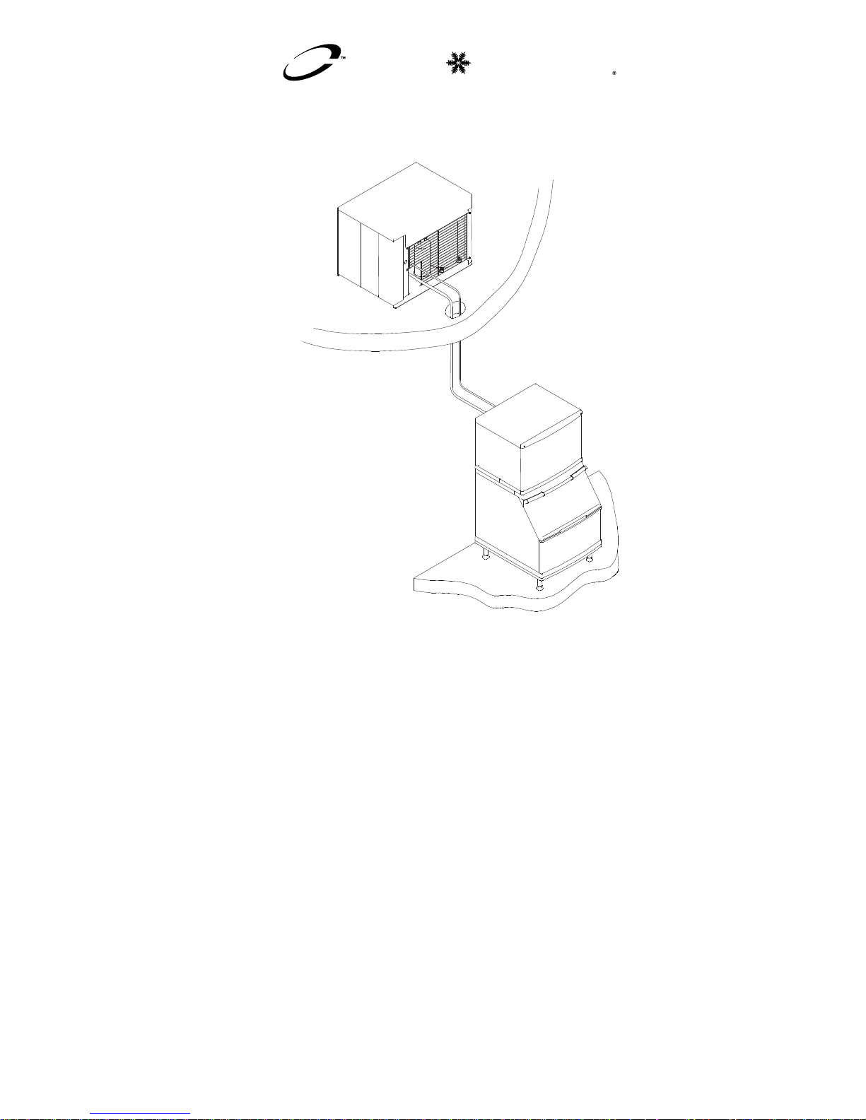
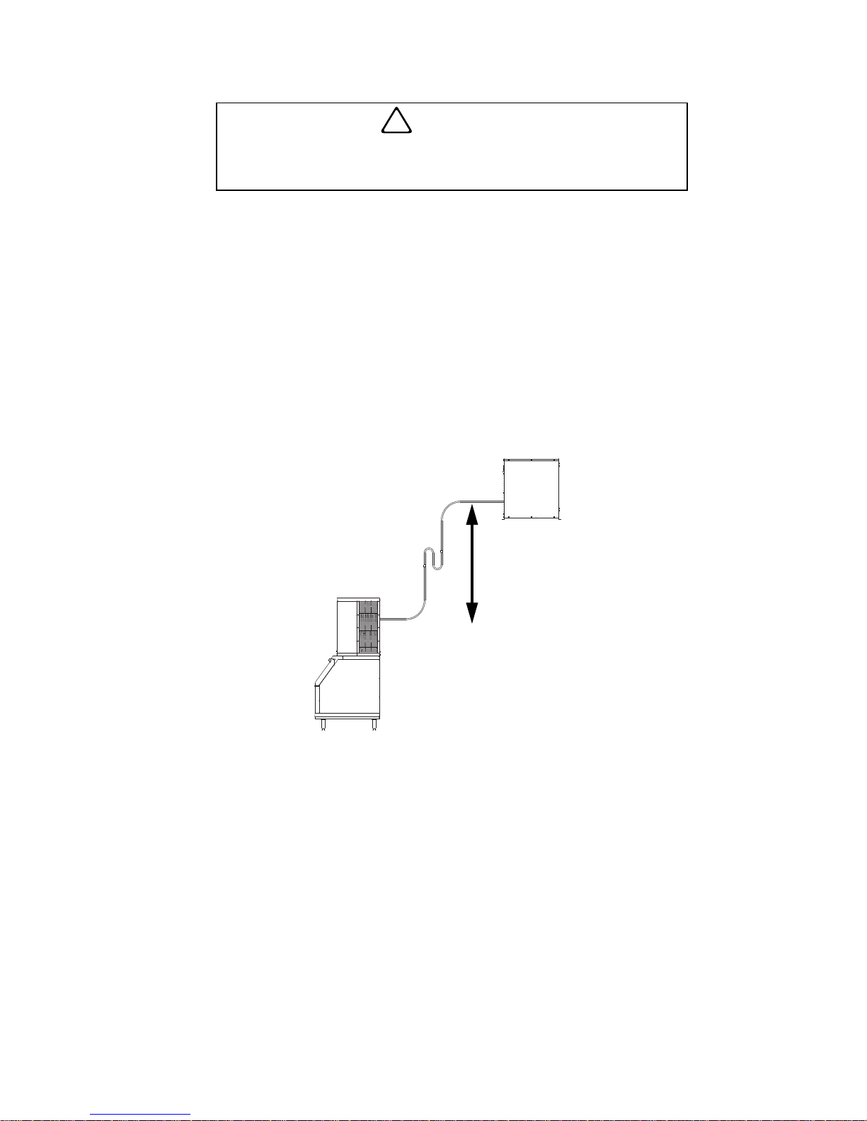
Refrigeration Line Set Installation
Refrigeration line set installation consists of vertical
and horizontal line set distances between the ice
machine and the condensing unit. The following
guidelines, drawings and calculation methods must be
followed to assure proper oil return and CVD
®
Condensing Unit/ice Machine operation.
Step 1. Prior to installation of the ice machine and
CVD
®
Condensing Unit be sure that the distance
between them is within the line set routing guidelines
outlined in this manual.
Step 2. Properly route refrigeration tubing between the
Ice Machine Head Section and the CVD
®
Condensing
Unit.
For a roof/wall penetration, cut a 3-in. (76.2 mm)
circular hole in the wall or roof for routing of
refrigeration tubing, as required. A qualified person
must perform all roof penetrations.
A. LINE SET LENGTH
!
Warning
Potential Personal Injury Situation
The ice machine head section contains the
refrigerant charge. Installation and brazing of the line
sets must be performed by a properly trained
refrigeration technician aware of the dangers of
dealing with refrigerant charged equipment.
!
Caution
QuietQube® Ice Machines will not function with line
sets greater than 100 ft. (30.5 m). Do not attempt to
go beyond this distance and add refrigerant charge
to compensate!
Page 28
–18–
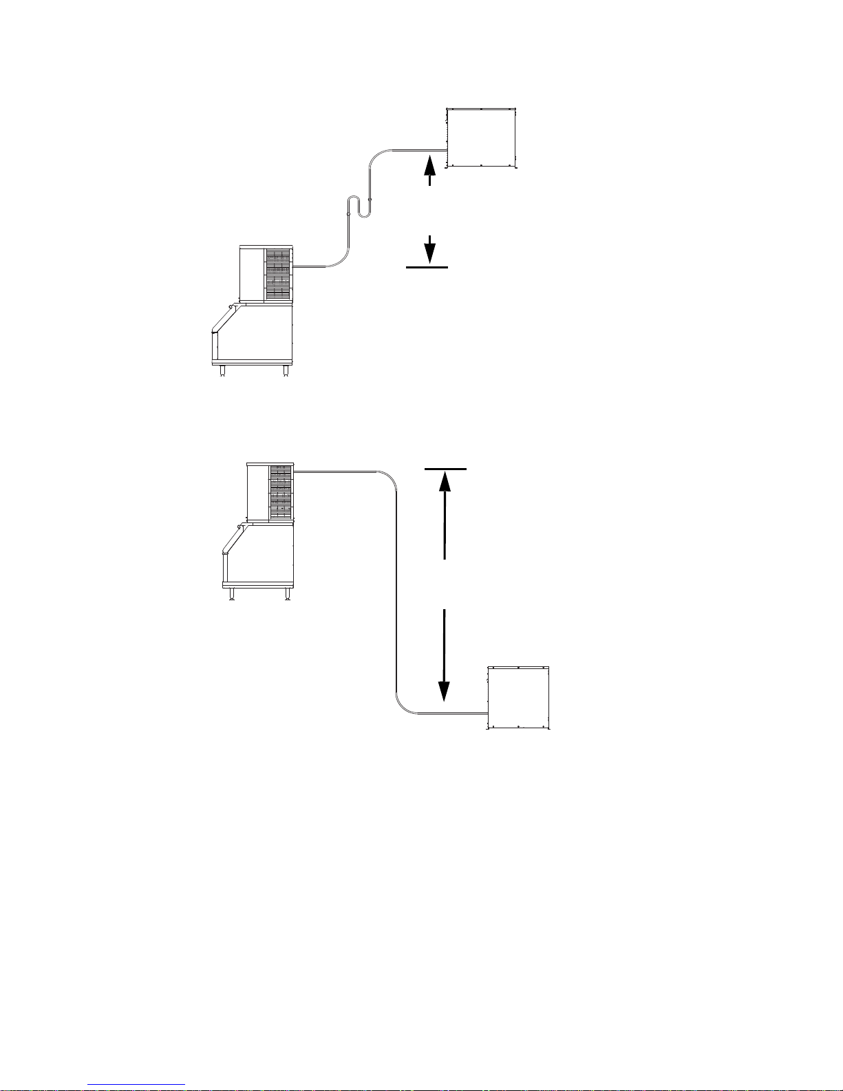
B. LINE SET RISE OR DROP
35 ft. (10.7 m) Rise: The maximum distance the CVD®
Condensing Unit can be above the ice machine.
15 ft. (4.5 m) Drop: The maximum distance the CVD®
Condensing Unit can be below the ice machine.
SV1751
35 FT. (10.7 M)
MAXIMUM
DISTANCE
SV1750
15 FT. (4.5 M)
MAXIMUM
DISTANCE
Page 29
–19–
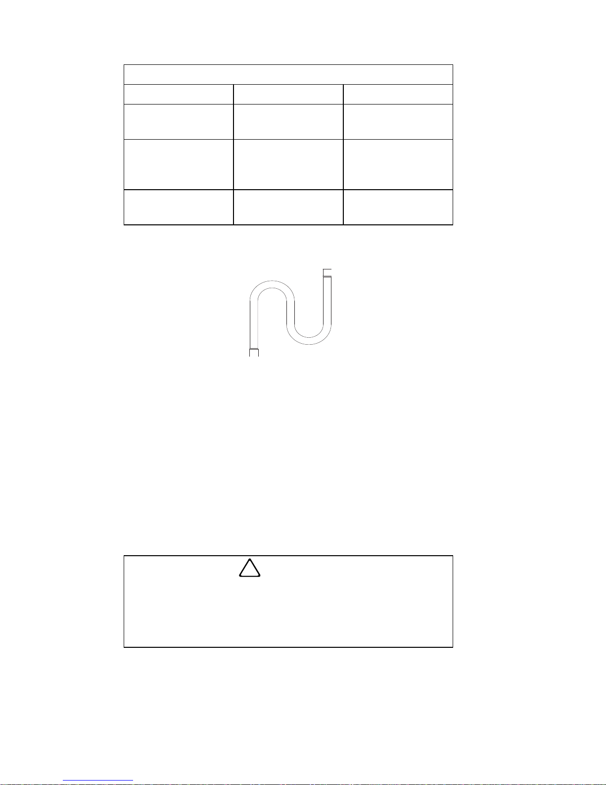
C. SUCTION LINE OIL TRAPS
0 to 20 ft. (0 to 6.1 m) Rise: The ice machine head
section has one oil trap built in which allows for a
maximum condenser rise of 20 ft. (6.1 m) without
additional traps in the suction line.
21 to 35 ft. (6.4 to 10.7 m) Rise: The suction line
requires an additional oil trap (“S” type) to be installed.
Install the trap as close as possible to midpoint
between the ice machine head section and CVD
®
Condensing Unit. S-Trap Kits are available from
Manitowoc (refer to chart).
!
Caution
Do not form unwanted traps in refrigeration lines.
Never coil excess refrigeration tubing.
SV1751
21 FT. OR
MORE RISE
ADDITIONAL
TRAP KIT
REQUIRED.
Page 30
–20–
SERVICE LOOP
A service loop in the line set permits easy access to
the ice machine for cleaning and service.
The supplied service loop is an installation
requirement. Excess tubing must allow 180 degree
rotation of the ice machine.
A service loop is no t considered an oil trap.
The se rvice loop is not included when calcu lating
the length, rise or drop of the tubing run.
Do not use hard rigid copper for the service loo p.
Manitowoc S-Trap Kit
Model S-Trap Kit # Tubing Size
Q0600C
Q0800C
K00172
5/8 in.
(15.9 mm)
Q1000C
SU1000C
Q1400C
K00166
3/4 in.
(19.1 mm)
QDUAL K00164
7/8 in.
(22.2 mm)
!
Caution
If a line set has a rise followed by a drop, another
rise cannot be made. Likewise, if a line set has a
drop followed by a rise, another drop cannot be
made.
SV1760
Page 31

–21–
Step 3. When the line set requires shortening or
lengthening, do so before connecting the line set to
the ice machine head section or the CVD
®
Condensing
Unit.
Step 4. To prevent oxidation of the copper, purge line
set and condensing unit with dry nitrogen while
brazing. .
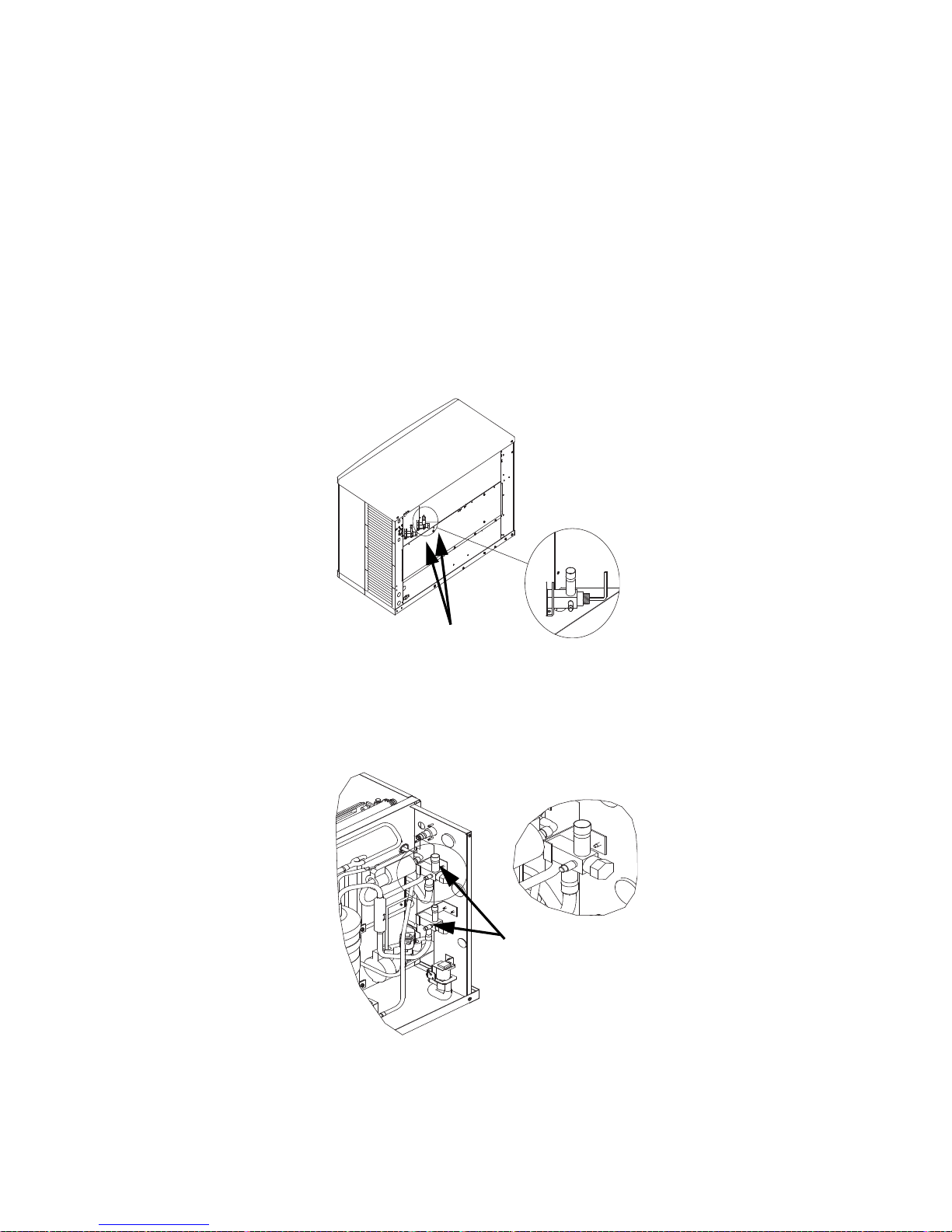
CONNECT THE LINE SET TO THE ICE MACHINE
HEAD SECTION
The line set shut-off valves at the back of the ice
machine must remain closed and be protected from
heat during the brazing process. Wrap the valves in a
wet rag or other type of heat sink prior to brazing. Cool
braze joint with water immediately after brazing to
prevent heat migration to the valve.
!
Caution
Do not form unwanted traps in refrigeration lines.
Never coil excess refrigeration tubing.
!
Warning
The ice machine head section contains refrigerant
charge. The ice machine head section contains
three (3) refrigeration valves that must remain
closed until proper installation of the line sets is
completed.
SV1757
VA LVES MUST REMAIN CLOSED
AND BE PROTECTED FROM
HEAT WHEN BRAZING
(WRAP WITH WET RAG).
Q0600C/Q0800C/Q1000C SHOWN
Page 32

–22–
CONNECT THE LINE SET TO THE CVD®
CONDENSING UNIT
The compressor oil rapidly absorbs moisture. Be
prepared to complete line set installation and start
your evacuation process in order to minimize the time
the compressor is exposed to the atmosphere.
(Maximum amount of time the system can be exposed
to the atmosphere is 15 minutes.)
The line set can be routed for entry through the front or
left side of the condensing unit.
Remove knockout for preferred location.
Insert supplied plastic bushings in knockout holes to
prevent tubing from contacting sheet metal.
Use the suppl ied 90° elbows to route tubing.
Cut the tubing ends of the suction and liquid lines
and braze line sets to the condensing unit.
!
Warning
The condensing unit ships from the factory
pressurized with a 50/50 mixture of nitrogen/helium.
Bleed off pressure from both suction and liquid line
access ports prior to cutting into refrigeration lines.
PT1284A
MINIMIZE THE TIME THE REFRIGERATION
SYSTEM IS EXPOSED T O THE ATMOSPHERE
(15 MINUTES MAXIMUM).
SUCTION
FILTER
SUCTION LINE
Page 33

–23–
Step 5. Schrader valve core removal tools that allow
for removal and installation of the valve cores without
removing manifold gauge set hoses are recommended
to decrease the evacuation time.
Leave the line set shut-off valves closed (front seated).
Pressure test the line sets and CVD
®
Condensing Unit
with 150 psig of dry nitrogen. Add nitrogen at the line
set shut-off valves located at the back of the ice
machine. Complete the pressure test, verify no leaks
are present and remove the nitrogen from the system
before connecting the vacuum pump. Connect a
vacuum pump to both of the line set shut-off valves
located at the back of the ice machine head section.
Evacuate to 250 microns (or less). To completely
evacuate the CVD
®
Condensing Unit, continue the
evacuation for 30 minutes after reaching the
500-micron point.
Liquid Line
Suction Line
SV3077
SV1757
CONNECT VACUUM
PUMP TO LINE SET
SHUT-OFF VALVES.
Page 34

–24–
If required, the line set and condensing unit can be
evacuated from the schrader valves located in the
CVD® Condensing Unit. Schrader valve core removal
tools (that allow for putting the cores back in without
removing vacuum pump hoses) must be used if
evacuating from the condensing unit side.
Isolate the vacuum pump from the line set shut-off
valves and/or condensing unit access ports prior to
proceeding.
PT1284
ALTERNATE CONNECTIONS AT
CONDENSING UNIT SCHRADER VALVES
Page 35
–25–
Step 6. The suction line, liquid line and receiver
service valves are closed during shipment and
installation.
Open the valves prior to starting the ice machine.
A. Slowly backseat (open – turn counterclockwise) the
suction line shut-off valve.
B. Slowly backseat (open – turn counterclockwise) the
liquid line shut-off valve.
C. Slowly backseat (open-turn counterclockwise) the
receiver service valve.
SV1762
USE ALLEN WRENCH TO OPEN
(TURN COUNTERCLOCKWISE)
LIQUID AND SUCTION LINE
SHUT-OFF VALVES.
Q0600C/Q0800C/Q1000C
SV1769c
USE ALLEN WRENCH
TO OPEN (TURN
COUNTERCLOCKWISE)
LIQUID AND SUCTION
LINE SHUT-OFF
VALVES.
Q1400C/QDUAL
SUCTION AND LIQUID LINE
SHUT-OFF VALVES
Page 36

–26–
Verify O-rings in schrader valve caps are intact and
reinstall on shut-off valves to prevent refrigerant
leakage. Replace shut-off valve access caps and
torque to the following specifications.
Replace cap on receiver service valve and tighten.
There is a liquid line solenoid valve at the outlet of the
receiver; refrigerant will not flow to the condensing unit
until the ice machine head section is started. Connect
power to both the ice machine head section and the
CVD
®
Condensing Unit. Place the ice machine toggle
switch into the ICE position; this will allow refrigerant
to enter the line set and condensing unit.
Step 7. Leak check the new line set connections at the
ice machine head section, condensing unit and S-trap
as well as all factory joints throughout the entire
system. Disconnect power to the CVD
®
Condensing
Unit. Place the ICE/OFF/CLEAN toggle switch in the
ICE position. This allows the low side and high side
Important
All refrigeration valve caps must be reinstalled to
prevent future refrigeration leaks.
Torque Values
S tem 18-20 ft. lbs.
Caps 12-15 ft. lbs.
Schraeder Core 1.5-3 in. lbs.
SV1756
TURN
COUNTERCLOCKWISE
TO OPEN.
RECEIVER SERVICE
VALVE CAP
(TURN COUNTERCLOCKWISE
TO REMOVE.)
RECEIVER SERVICE VALVE
Page 37

–27–
pressures to equalize. Place the ICE/OFF/CLEAN
toggle switch in the OFF position. Connect power to
the CVD
®
Condensing Unit and allow system to pump
down.
Step 8. To prevent condensation, the entire suction
line including the shut-off valve must be insulated. All
insulation must be airtight and sealed at both ends.
The following insulation requirements prevent
condensation at 90°F (32.2°C) ambient 90% Relative
Humidity. If higher humidity is expected, increase
insulation thickness.
The entire suction line set, including the suction
service valve located on the back of the ice machine,
requires a minimum of 3/4 in. (12.7 mm) wall thickness
insulation.
The entire liquid line set requires a minimum of
1/4 in. (6.4 mm) wall thickness insulation.
Important
To prevent condensation, the entire suction line
including the shut-off valve must be insulated. All
insulation must be airtight and sealed at both ends.
This requires a minimum of 3/4 in. (12.7 mm)
insulation wall thickness with conditions at or below
90% humidity and 90° ambient. When higher
humidity will be experienced, insulation wall
thickness will need to be increased.
Page 38

–28–
SUCTION SHUT-OFF VALVE INSULATION
The preformed suction shut-off valve insulation is
located in the plastic bag taped to the water curtain.
A. Verify valve and schrader caps are tightened to
specifications (see step 6).
B. Place insulation over schrader valve cap and left
side of valve. Position the tab between the
mounting bracket and rear panel.
C. Fold insulation and hold against right hand side of
valve while securing with electrical tape. Seal the
line set insulation to the shut-off valve insulation
with electrical tape.
PREFORMED
INSULATION
TIGHTEN VALVE CAPS
TO SPECIFICATIONS.
PLACE TAB BETWEEN
VALVE BODY AND PANEL.
FOLD INSULA TION OVER
RIGHT SIDE OF VALVE
AND SECURE WITH
ELECTRICAL TAPE.
Page 39

–29–
3 PHASE SCROLL COMPRESSOR ROTATION
CVD2075 ONLY
A trained and qualified technician must verify
compressor rotation at equipment startup or
compressor warranty will be void. Incorrect rotation of
a scroll compressor can be identified by:
Noisy compressor operation
Elevated suction pressure
Low discharge pressure
Compressor trips on overload protector
To change compressor rotation, reverse (exchange
locations) any two incoming power supply leads.
CONDENSING UNIT HEAT OF REJECTION
Ice machines, like other refrigeration equipment, reject
heat through the condenser. It is necessary to know
the amount of heat rejected by an ice machine when
determining the additional BTUH requirements for air
conditioning equipment.
Self-contained air-cooled ice machines add the total
BTUH load to a conditioned space.
QuietQube® Ice Machine head sections add an
insignificant amount of load to a conditioned space.
Series
Condensing
Unit
Heat of Rejection*
A/C** Peak
CVD0675 9,000 13,900
CVD0875 12,400 19,500
CVD1075 16,000 24,700
CVD1475
CVD1476
24,000 35,000
CVD1875 28,000 42,000
CVD2075 39,000 53,000
**B.T.U./Hour
**Because the heat of rejection varies during the ice
making cycle, the figure shown is an average.
Page 40

–30–
Operational Checks
GENERAL
Your Manitowoc ice machine was factory-operated
and adjusted before shipment. Normally, a newly
installed ice machine does not require any adjustment.
To ensure proper operation, always perform these
Operational Checks when starting the ice machine:
For t he First Time
After a Prolonged Out-of-Service Period
After Cleaning and Sanitizing
Routine adjustments and maintenance procedures
outlined in this manual are not covered by the
warranty.
WATER LEVEL
Q0600C/Q0800C/Q1000C/QDUAL
The water level sensor is set to maintain the proper
water level above the water pump housing. The water
level is not adjustable.
If the water level is incorrect, check the water level
probe for damage (probe bent, etc.). Clean, repair or
replace the probe as necessary.
WATER LEVEL PROBE
WATER LEVEL
SENSOR PROBE
WATER
PUMP
WATER LEVEL
ABOVE HOUSING
Page 41

–31–
Q1400C/SU1000C
1. Check the water level while the ice machine is in
the Clean mode and the water pump is running.
The correct water level above the water pump
impeller housing is:
Q1400C - 1/8-1/2 in. (3-12.5 mm)
SU1000C - 1/8-1/4 in. (3-6.35 mm)
2. The float valve is factory-set for the proper water
level. If adjustments are necessary:
A. Loosen the two screws on the float valve
bracket.
B. Raise or lower the float valve assembly as
necessary, then tighten the screws.
If further adjustment is required, carefully bend the
float arm to achieve the correct water level.
WATER
LEVEL
Page 42

–32–
ICE THICKNESS CHECK
After a Harvest cycle, inspect the ice cubes in the ice
storage bin. The ice thickness probe is set to maintain
an ice bridge of 1/8 in. (3.2 mm). If an adjustment is
needed, follow the steps below.
1. Turn the ice thickness probe adjustment screw
clockwise for a thicker ice bridge, or
counterclockwise for a thinner ice bridge.
2. Make sure the ice thickness probe wire and bracket
do not restrict movement of the probe.
SV3113
ADJUSTING
SCREW
1/8 IN. ICE BRIDGE
THICKNESS
ICE THICKNESS ADJUSTMENT
1/8” ICE BRIDGE THICKNESS
Page 43

–33–
HARVEST SEQUENCE WATER PURGE
Q0600C/Q0800C/Q1000C/SU1000C/QDUAL
The Harvest sequence water purge adjustment may
only be used when the ice machine is hooked up to
special water systems, such as a de-ionized water
treatment system.
The Harvest sequence water purge may be set to
15, 30, or 45 seconds.
During the Harvest sequence water purge, the water
fill valve energizes and de-energizes by time. The
water purge must be at the factory setting of
45
seconds for the water fill valve to energize during
the last 15 seconds of the water purge. If it is set to
less than 45 seconds, the water fill valve will not
energize during the water purge.
Important
The Harvest sequence water purge is factory-set at
45 seconds. A shorter purge setting (with standard
water supplies such as city water) is not recommended.
This can increase water system cleaning and
sanitizing requirements.
15
30
45
SV1208
CONTROL
BOARD
WATER PURGE
ADJUSTMENT
Page 44
–34–
Interior Cleaning and Sanitizing
NOTE: Clean and sanitize the ice machine every six
months for efficient operation. If the ice machine
requires more frequent cleaning and sanitizing,
consult a water care professional to test the water
quality and recommend appropriate water treatment or
installation of the AuCS
®
(Automatic Cleanin g System)
Accessory. If requi red, an extre mely dirty ice machine
may be taken apart for cleaning and sanitizing.
NOTE: The SU1024YC is designed for
installation on a SerVend UC-300 dispenser
only. Refer to the SerVend UC-300
Installation, Use and Care Manual for
dispenser cleaning/sanitizing procedures.
!
Caution
Use only Manitowoc approved Ice Machine Cleaner
(part number 94-0546-3) and Sanitizer (part number
94-0565-3). It is a violation of Federal law to use
these solutions in a manner inconsistent with their
labeling. Read and understand all labels printed on
bottles before use.
!
Caution
Do not mix Ice Machine Cleaner and Sanitizer
solutions together. It is a violation of Federal law to
use these solutions in a manner inconsistent with
their labeling.
!
Warning
Wear rubber gloves and safety goggles (and/or face
shield) when handling Ice Machine Cleaner or
Sanitizer.
Page 45

–35–
Manitowoc’s Patented Cleanin g or San itizi ng
Technology
Manitowoc ice machines include technology that
allows the initiation and completion of a cleaning or
sanitizing cycle at the flip of a switch. This cycle will
permit cleaning or sanitizing of all surfaces that come
in contact with the water distribution system. Periodic
maintenance must be performed that includes
sanitizing the bin (or dispenser) and adjacent surface
areas, which cannot be contacted by the water
distribution system.
This technology will also allow initiation and
completion of a Clean or Sanitize cycle, after which the
ice machine automatically starts ice making again.
Refer to the cleaning or sanitizing procedure for
complete details.
The AuCS
®
Accessory can be set to automatically
start and finish a Clean or Sanitize cycle every 2, 4, or
12 weeks. This accessory monitors ice-making cycles
and initiates a cleaning or sanitizing cycle
automatically. After completion of the cleaning or
sanitizing cycle, the ice machine returns to ice making
automatically. Refer to Automatic Cleaning System
(AuCS
®
) Accessory for further details.
Page 46

–36–
ALPHASAN
The goal of AlphaSan is to keep the plastic surfaces
of an ice machine cleaner, by reducing or delaying the
formation of biofilm. The active ingredient in
AlphaSan
is the element silver in the form of silver
ions (Ag+). AlphaSan
slowly releases silver ions via
an ion exchange mechanism. When AlphaSan
is
compounded directly into a plastic part, a controlled
release of silver ions from the surface is regulated to
maintain an effective concentration at or near the
surface of the plastic ice machine part.
AlphaSan’s
unique ability to effectively control the
release of silver not only protects against undesired
discoloration of the plastic, but also will last the life of
the plastic part. Although AlphaSan helps prevent
biofilm build up it does not eliminate the need for
periodic cleaning and maintenance. AlphaSan
has
no adverse effect on the taste of the ice or beverage.
Page 47

–37–
CLEANING PROCEDURE
Ice machine cleaner is used to remove lime scale or
other mineral deposits. It is not used to remove algae
or slime. Refer to “Sanitizing Procedure” on page 39
for removal of algae and slime. To initiate a cleaning
cycle using Manitowoc’s Patented Cleaning
Technology, use th e following procedure.
Step 1. Set the toggle switch to the OFF position after
ice falls from the evaporator at the end of a Harvest
cycle. Or, set the switch to the OFF position and allow
the ice to melt off the evaporator.
Step 2. To start a cleaning cycle, move the toggle
switch to the CLEAN position. The water will flow
through the water dump valve and down the drain. The
Clean light* will turn on to indicate the ice machine is
in the cleaning mode.
Step 3. Wait about one minute or until water starts to
flow over the evaporator.
Step 4. Add the proper amount of Manitowoc Ice
Machine Cleaner to the water trough.
*The Q1400C ice machine control board does not energize a
Clean light.
!
Caution
Never use anything to force ice from the evaporator.
Damage may result.
QuietQube® Models Amount of Cleaner
Q0600C/Q0800C/
SU1000C/Q1400C
5 ounces (150 ml)
Q1000C/QDUAL 9 ounces (270 ml)
Page 48

–38–
Step 5. The ice machine will automatically time out a
ten-minute cleaning cycle, followed by six Rinse
cycles, and then stop. The Clean light* will turn off to
indicate the cleaning mode is completed. This entire
cycle lasts approximately 25 minutes.
NOTE: Periodic cleaning must be performed on
adjacent surface areas not contacted by the water
distribution system.
Step 6. When the cleaning process stops, move the
toggle switch to the OFF position. Refer to “Sanitizing
Procedure” on page 39.
Step 7.**
A. The ice machine may be set to start and finish a
cleaning procedure, and then automatically start ice
making again.
B. Wait about one minute in to the cleaning cycle (until
water starts to flow over the evaporator), then move
the switch from CLEAN to ICE position.
C. When the cleaning cycle is completed, the Clean
light will turn off and an ice making sequence will
start automatically.
NOTE: After the toggle switch is moved to the ICE
position, opening the curtain (bin switch) will interrupt
the cleaning sequence. The sequence will resume
from the point of interruption when the curtain (bin
switch) closes.
NOTE: The SU1024YC is designed for installation on
a SerVend UC-300 dispenser only. Refer to the
SerV end UC-300 Installation Use and Care Manual for
dispenser cleaning/sanitizing procedures.
**The Q1400C ice machine control board does not energize
a Clean light.
**The Q1400C ice machine control board can not perform
step 7, and must remain in the CLEAN position until the
Clean cycle is finished. Moving the toggle switch to the ICE
position will initiate a Freeze cycle.
Page 49

–39–
SANITIZING PROCEDURE
Use sanitizer to remove algae or slime. Do not use it to
remove lime scale or other mineral deposits. To initiate
a sanitizing cycle using Manitowoc’s Patented
Cleaning/Sanitizing Technology, use the following
procedure.
Step 1. Set the toggle switch to the OFF position after
ice falls from the evaporator at the end of a Harvest
cycle. Or, set the switch to the OFF position and allow
the ice to melt off the evaporator.
Step 2. To start a sanitizing cycle, move the toggle
switch to the CLEAN position. The water will flow
through the water dump valve and down the drain. The
Clean light* will turn on to indicate the ice machine is
in the cleaning mode.
Step 3. Wait about one minute or until water starts to
flow over the evaporator.
Step 4. Add the proper amount of Manitowoc Ice
Machine Sanitizer to the water trough.
*The Q1400C ice machine control board does not energize a
Clean light.
!
Caution
Never use anything to force ice from the evaporator.
Damage may result.
QuietQube® Models Amount of Sanitizer
Q0600C/Q0800C/Q1000C/
SU1000C/Q1400C
3 ounces (90 ml)
QDUAL 6 ounces (180 ml)
Page 50

–40–
Step 5. The ice machine will automatically time out a
ten-minute sanitizing cycle, followed by six Rinse
cycles, and then stop. The Clean light* will turn off to
indicate the sanitizing mode is completed. This entire
cycle lasts approximately 25 minutes.
NOTE: Periodic cleaning must be performed on
adjacent surface areas not contacted by the water
distribution system. If the bin requires sanitizing,
remove all of the ice and sanitize it with a solution of
1
oz. (30 ml) of sanitizer with up to 4 gal. (15 l) of
water.
Step 6. When the sanitizing process stops, move the
toggle switch to the ICE position to start ice making
again.
Step 7.**
A. The ice machine may be set to start and finish a
sanitizing procedure, and then automatically start
ice making again.
B. Wait about one minute into the sanitizing cycle
(until water starts to flow over the evaporator), then
move the switch from CLEAN to ICE position.
C. When the sa nitizing cycle is completed, the Clean
light will turn off and an ice making sequence will
start automatically.
NOTE: After the toggle switch is moved to the ICE
position, opening the curtain (bin switch) will interrupt
the cleaning sequence. The sequence will resume
from the point of interruption when the curtain (bin
switch) closes.
NOTE: The SU1024YC is designed for installation on
a SerVend UC-300 dispenser only. Refer to the
SerV end UC-300 Installation Use and Care Manual for
dispenser cleaning/sanitizing procedures.
**The Q1400C ice machine control board does not energize
a Clean light.
**The Q1400C ice machine control board can not perform
step 7, and must remain in the CLEAN position until the
Clean cycle is finished. Moving the toggle switch to the ICE
position will initiate a Freeze cycle.
Page 51

–41–
Automatic Cleaning System (AuCS®) Accessory
This accessory monitors ice-making cycles and
initiates cleaning (or sanitizing) procedures
automatically. T he AuCS® Accessory can be set to
automatically clean or sanitize the ice machine every
2, 4, or 12 weeks. Periodic maintenance must be
performed that includes cleaning or sanitizing the bin
(or dispenser) and adjacent surface areas, which can
not be contacted by the water distribution system.
AUTOMATIC OPERATION
The following occurs when the toggle switch is in the
ICE position:
The ice machine control board counts the number of
ice Harvest cycles.
The AuCS® Accessory interrupts the ice making
mode and starts the cleaning (or sanitizing) mode
when the harvest count equals the “Frequency of
Cleaning” setting of the AuCS
®
.
When the automatic cleaning (or sanitizing) cycle is
complete (approximately 25 minutes), ice making
resumes automatically, an d the “Harvest Count” is
reset to zero.
!
Caution
Refer to the AuCS® Accessory Installation, Use and
Care Guide for complete details on the installation,
operation, maintenance and cautio nary statements
of this accessory.
Important
Opening the curtain switch will interrupt the cleaning
or sanitizing sequence. The sequence will resume
from the point of interruption when the curtain
recloses.
Page 52

–42–
MANUAL START OPERATION
Step 1. Set the toggle switch to the OFF position after
ice falls from the evaporator at the end of a Harvest
cycle. Or, set the switch to the OFF position and allow
the ice to melt off the evaporator.
Step 2. To start the automatic cleaning system, move
the toggle switch to the CLEAN position. The water will
flow through the water dump valve and down the
drain. The Clean light* will turn on to indicate the ice
machine is in the cleaning mode. The AuCS
®
then
automatically adds cleaner or sanitizer to the ice
machine.
Step 3. The ice machine will automatically time out a
ten-minute cleaning or sanitizing cycle, followed by six
Rinse cycles, de-energize the Clean light* and stop.
This entire cycle lasts approximately 25 minutes.
Step 4. After the cleaning or sanitizing cycle stops,
move the toggle switch to ICE position.
Step 5.**
A. The ice machine may be set to start and finish a
cleaning or sanitizing cycle, then automatically start
ice making again.
B. You must wait about one minute into the cleaning
cycle (until water starts to flow over the evaporator),
then move the toggle switch from CLEAN to ICE
position.
C. When the cleaning or sanitizing cycle is completed,
the Clean light will turn off and an ice-making
sequence will start automatically.
**The Q1400C ice machine control board does not energize
a Clean light.
**The Q1400C ice machine control board can not perform
step 7, and must remain in the CLEAN position until the
Clean cycle is finished. Moving the toggle switch to the ICE
position will initiate the Rinse cycles. The six Rinse cycles
must be completed before a Freeze cycle can be initiated.
!
Caution
Never use anything to force ice from the evaporator.
Damage may result.
Page 53

–43–
Removal of Parts for Cleaning or Sanitizing
1. Turn off the water supply to the ice machine at the
water service valve.
2. Remove the water curtain and the components you
want to clean or sanitize. See the following pages
for removal procedures for these parts.
3. Soak the removed part(s) in a properly mixed
solution.
4. Use a soft-bristle brush or sponge (NOT a wire
brush) to carefully clean the parts.
!
Warning
Disconnect electric power to the ice machine at the
electric switch box before proceeding.
!
Warning
Wear rubber gloves and safety goggles (and/or face
shield) when handling Ice Machine Cleaner or
Sanitizer.
Solution Type Water Mixed With
Cleaner 1 gal. (4 l)
16 oz. (500 ml)
cleaner
Sanitizer 4 gal. (15 l)
1 oz. (30 ml)
sanitizer
!
Warning
Do not mix Cleaner and Sanitizer solutions together .
It is a violation of Federal law to use these solutions
in a manner inconsistent with their labeling.
Page 54

–44–
5. Use the solution and a brush to clean the top,
sides, and bottom evaporator extrusions; the inside
of the ice machine panels; and the entire inside of
the bin.
6. Thoroughly rinse all of the parts and surfaces with
clean water.
7. Install the removed parts.
NOTE: Incomplete rinsing of the ice thickness probe
or water level probe may leave a residue. This could
cause the ice machine to malfunction. For best results,
brush or wipe the probe off while rinsing it. Thoroughly
dry the probe before installing it.
8. Turn on the water and electrical supply.
9. Verify the ice thickness probe is properly adjusted.
!
Caution
Do not immerse the water pump motor in the
cleaning or sanitizing solution.
Page 55

–45–
WATER DUMP VALVE
The water dump valve normally does not require
removal for cleaning. To determine if removal is
necessary:
1. Locate the water dump valve.
2. Set the toggle switch to ICE.
3. While the ice machine is in the Freeze mode, check
the dump valve’s clear plastic outlet drain hose for
leakage.
A. If the dump valve is leaking, remove,
disassemble and clean it.
B. If the dump valve is not leaking, do not remove
it. Instead, follow standard ice machine cleaning
procedures.
Follow the procedure below to remove the dump
valve.
1. If so equipped, remove the water dump valve shield
from its mounting bracket.
2. Lift and slide the coil retainer cap from the top of the
coil.
3. Note the position of the coil assembly on the valve
for assembly later. Leaving the wires attached, lift
the coil assembly off the valve body and the
enclosing tube.
4. Press down on the plastic nut on the enclosing tube
and rotate it 1/4 turn. Remove the enclosing tube,
plunger, and plastic gasket from the valve body.
NOTE: At this point, the water dump valve can easily
be cleaned. If complete removal is desired, continue
with step 5.
!
Warning
Disconnect the electric power to the ice machine at
the electric service switch box and turn off the water
supply before proceeding.
Page 56

–46–
NOTE: During cleaning, do not stretch, damage or
remove the spring from the plunger. If it is removed,
slide the spring’s flared end into the plunger’s slotted
top opening until the spring contacts the plunger
spring stop.
5. Remove the valve body.
6. Remove the tubing from the dump valve by twisting
the clamps off.
Remove the two screws securing the dump valve and
the mounting bracket.
Important
The plunger and the inside of the enclosing tube
must be completely dry before assembly.
DUMP VALVE REMOVAL
DO NOT
DISCONNECT
WIRES A T COIL.
RETAINING
CAP
WATER
DUMP
VALVE
VALVE
SHIELD
DUMP VALVE DISASSEMBLY
PLUNGER
SPRING STOP
PLUNGER
DIAPHRAGM
VALVE BODY
ENCLOSING
TUBE
COIL
CAP
SPRING
Page 57

–47–
WATER PUMP
1. Disconnect the water pump power cord.
2. Disconnect the hose from the pump outlet.
3. Loosen the screws securing the pump, mounting
bracket to the bulkhead.
4. Lift the pump and bracket assembly off the screws.
!
Warning
Disconnect the electric power to the ice machine at
the electric service switch box and turn off the water
supply.
SV1618
WATER
PUMP
POWER
CORD
LOOSEN
SCREWS.
WATER PUMP REMOVAL
(Q0600C/Q0800C/Q1000C SHOWN)
Page 58

–48–
ICE THICKNESS PROBE
1. Compress the side of the ice thickness probe near
the top hinge pin and remove it from the bracket.
NOTE: At this point, the ice thickness probe can easily
be cleaned. If complete removal is desired, continue
with step 2 below.
2. Disconnect the wire lead from the control board
inside the electrical control box.
!
Warning
Disconnect the electric power to the ice machine at
the electric service switch box and turn off the water
supply.
SV1619
DISCONNECT
WIRE LEAD.
ICE THICKNESS PROBE REMOVAL
COMPRESS
HINGE PIN
TO REMOVE.
Page 59

–49–
WATER LEVEL PROBE
Q0600C/Q0800C/Q1000C/QDUAL
1. Loosen the screw that holds the water level probe
in place. The probe can easily be cleaned at this
point without proceeding to step 2.
2. If complete removal is required, disconnect the wire
lead from the control board (1F) inside the electrical
control box.
!
Warning
Disconnect the electrical power to the ice machine at
the electrical disconnect before proceeding.
SV1621
WATER LEVEL PROBE REMOVAL
Q0600C/Q0800C/Q1000C Shown
SCREW
WATER
LEVEL
PROBE
WATER
TROUGH
ICE
MACHINE
SIDE
PANEL
WIRE
LEAD
Page 60

–50–
SPLASH SHIELD
Q1400C/QDUAL
1. Pull forward on left and right Nylatch connectors
until disengaged from ice machine (connectors
remain attached to splash shield).
2. Remove panel from front of ice machine by lifting
forward and up.
Important
Splash shield must be reinstalled to prevent water
leakage.
NYLATCH CONNECTORS
PULL FORWARD TO
DISENGAGE.
Q1400 Shown
Page 61

–51–
WATER CURTAIN
1. Gently flex the curtain in the center and remove it
from the right side.
2. Slide the left pin out.
SV1213
WATER CURTAIN REMOVAL
Page 62

–52–
FLOAT VALVE
SU1000C/Q1400C
1. Turn off the water supply to the ice machine at the
water service valve.
2. Turn the splash shield counterclockwise one or two
turns.
3. Pull the float valve forward and off the mounting
bracket.
4. Disconnect the water inlet tube from the float valve
at the compression fitting.
5. Remove the filter screen and cap for cleaning.
SV1217
FLOAT VALVE REMOVAL
WATER INLET
TUBE
COMPRESSION
FITTING
FIL TER SCR EEN
AND CAP
ON/OFF
SLIDE
SWITCH
SPLASH
SHIELD
Page 63

–53–
WATER INLET VALVE
Q0600C/Q0800C/Q1000C/QDUAL
The water inlet valve normally does not require
removal for cleaning. Follow the instructions below to
determine if removal is necessary.
1. Set the ICE/OFF/CLEAN switch to OFF. Locate the
water inlet (in the water area of the ice machine). It
directs water into the water trough.
2. When the ice machine is off, the water inlet valve
must completely stop water flow into the machine.
Watch for water flow. If water flows, remove,
disassemble and clean the valve.
3. When the ice machine is on, the water inlet valve
must allow the proper water flow through it. Set the
toggle switch to ON. Watch for water flow into the
ice machine. If the water flow is slow or only trickles
into the ice machine, remove, disassemble, and
clean the valve.
Continued on Next Page...
!
Warning
Disconnect the electric power to the ice machine at
the electric service switch box and turn off the water
supply before proceeding.
Page 64
–54–
Follow the procedure below to remove the water inlet
valve.
1. Remove the valve shield if necessary.
2. Remove the filter access screws that hold the valve
in place.
NOTE: The water inlet valve can be disas sembled and
cleaned without disconnecting the incoming water
supply line to the ice machine.
3. Remove, clean, and install the filter screen.
4. If necessary, remove the enclosing tube access
screws to clean interior components.
SV1622
WATER INLET VALVE REMOVAL
WATER
INLET
VALVE
FILTER
ACCESS
SCREWS
INCOMING
WATER
LINE
Page 65

–55–
WATER DISTRIBUTION TUBE
1. Disconnect the water hose from the distribution
tube.
2. Loosen the thumbscrews, which secure the
distribution tube.
3. Lift the end of the distribution tube with the hose
fitting up, and then slide it back and to the right.
!
Caution
Do not force this removal. Be sure the locating tab is
clear before sliding the distribution tube back.
SV1620
WATER DISTRIBUTION TUBE REMOVAL
THUMBSCREW
DISTRIBUTION
TUBE
1. LIFT UP.
2. SLIDE BACK.
3. SLIDE TO RIGHT.
THUMB-
SCREW
1
2
3
Page 66

–56–
4. Disassemble for cleaning.
A. Twist both of the inner tube ends until the tabs
line up with the keyways.
B. Pull the inner tube ends outward.
SV1211
WATER DISTRIBUTION TUBE DISASSEMBLY
INNER
TUBE
INNER
TUBE
KEYWAY
TAB
Page 67

–57–
WATER TROUGH REMOVAL
Q1400C/QDUAL
1. Remove the front splash shield, water pump and
float valve from the ice machine.
2. Remove the quarter turn fasteners (turn
counterclockwise) securing the trough in place.
3. Lift up and forward on the front of the water trough
while allowing the rear of the water trough to drop.
Remove the water trough from the ice machine.
SV1771B
REMOVE THE TWO
QUARTER TURN
FASTENERS BY TURNING
COUNTERCLOCKWISE.
WATER TROUGH REMOVAL
Page 68

–58–
WATER TROUGH REMOVAL
SU1000C (SerVend UC-300 Dispenser)
1. Remove the quarter turn fasteners (turn
counterclockwise) securing the trough in place.
2. Pull forward on the water trough until the rear pins
disengage from the water trough.
3. Lift up and forward on the front of the water trough
while allowing the rear of the water trough to drop.
4. Remove the water trough from the ice machine.
Pins Located Behind Water Curtain
1
Page 69

–63–
Removal from Service/Winterization
GENERAL
S pecial precautions must be taken if the ice machine is
to be removed from service for an extended period of
time or exposed to ambient temperatures of 32°F
(0°C) or below.
1. Place the ice machine toggle switch in the OFF
position.
2. Turn of f the wat er supply.
3. Remove the water from the water trough.
4. Disconnect and drain the incoming ice-making
water line at the rear of the ice machine.
5. Blow compressed air in the drain openings in the
rear of the ice machine until no more water comes
out of the drain.
6. Place the toggle switch in the ICE position, then
wait 45 seconds for the water fill solenoid valve to
energize. Blow compressed air through the
incoming water supply in the rear of the ice
machine until no more water comes out of the inlet
water line.
7. Make sure water is not trapped in any of the water
lines, drain lines, distribution tubes, etc.
!
Caution
If water is allowed to remain in the ice machine in
freezing temperatures, severe damage to some
components could result. Damage of this nature is
not covered by the warranty.
Page 70

–64–
CVD1476 WATER COOLED CONDENSING UNIT
Place the ice machine toggle switch into the OFF
position.
1. "Front seat" (shut off) the receiver service valve.
Hang a tag on the switch as a reminder to open the
valve before restarting.
2. Perform steps 1-6 under "Q1400C Head Section".
3. Insert a large screwdriver between the bottom
spring coils of the water regulating valve. Pry
upward to open the valve.
4. Hold the valve open and blow compressed air
through the condenser until no water remains.
AuCS® ACCESSORY
Refer to the AuCS® Accessory manual for
Winterization of the AuCS
®
Accessory.
Page 71

–65–
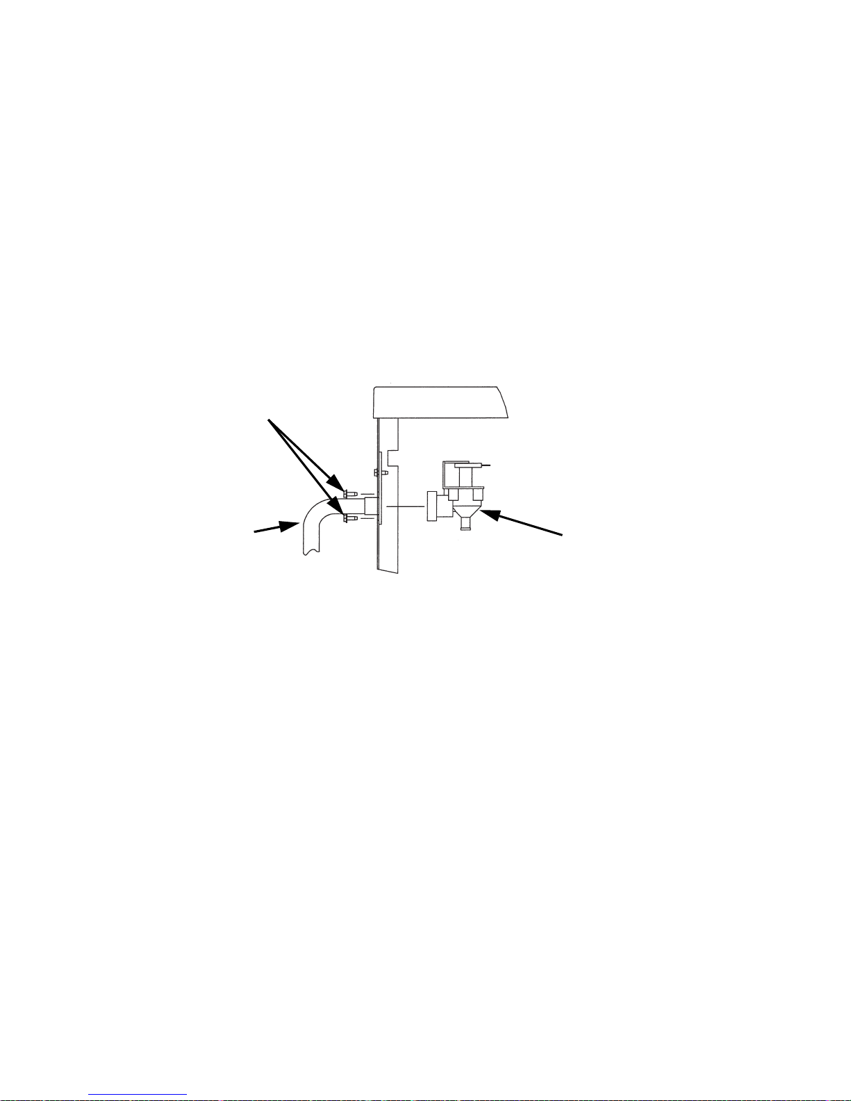
Component Identification
ICE MACHINE HEAD SECTION
Q0600C/Q0800C/Q1000C
SV1754
WATER INLET
VALVE
LIQUID LINE
SOLENOID
VALVE
WATER DUMP
VALVE
DRAIN HOSE
LIQUID LINE
SHUT-OFF VALVE
SUCTION LINE
SHUT-OFF VALVE
RECEIVER
RECEIVER
SERVICE
VALVE
COOL VAPOR
VALVE
Page 72

–66–
Q0600C/Q0800C/Q1000C
SV1605A
FLOW CLAMP USED
ON REGULAR SIZE
CUBE ONLY
DISTRIBUTION
TUBE
ICE THICKNESS
PROBE
EVAPORATOR
WATER CURTAIN
WATER TROUGH
WATER PUMP
ICE/OFF/CLEAN
SWITCH
Page 73

–67–
SU1000C/SerVend UC-300 Dispenser
Ice Thickness Probe
Electrical Compartment &
Toggle Switch
Dump Valve
Water Trough
Water Curtain
Water Pump/Float
Valve Access Panels
Cool Vapor
Valve
Water Pump
Liquid Line Drier
Float Valve
Liquid Line
Solenoid
Valve
Page 74

–68–
Q1400C
ICE/OFF/CLEAN
SWITCH
SV1770LH
ICE
THICKNESS
PROBE
COOL VAPOR
VALVE
FLOAT VALVE
WATER INLET
SUCTION LINE
SHUT-OFF VALVE
SV1770RH
LIQUID LINE
SHUT-OFF VALVE
COOL VAPOR
VALVE
WATER DUMP
VALVE
LIQUID LINE
SOLENOID
VALVE
RECEIVER
RECEIVER
SERVICE
VALVE
Receiver Service Valve
Page 75

–69–
QDUAL
DISTRIBUTION
TUBE
SV1780
EVAPORATOR WATER PUMP
WATER CURTAIN
WATER TROUGH
Page 76

–70–
CVD® CONDENSING UNIT
CVD0675/CVD0875/CVD1075/CVD1475
ACCESS VALVE
CONDENSER
FAN MOTOR
HEAD PRESSURE
CONTROL V AL VE
AIR CONDENSER
COMPRESSOR
SUCTION
ACCUMULATOR
LIQUID LINE AND
SUCTION LINE
CONNECTION POINTS
ELECTRICAL
COMPARTMENT
SV2085
Page 77

–71–
CVD1476
LIQUID LINE AND
SUCTION LINE
CONNECTION POINTS
SUCTION
ACCUMULATOR
COMPRESSOR
WATER COOLED
CONDENSER
HEAD
PRESSURE
CONTROL
VALVE
ELECTRICAL
COMPARTMENT
WATER
REGULATING
VALVE
Page 78

–72–
CVD1875/CVD2075
ACCESS VALVES
CVD1875 SHOWN
CONDENSER
FAN MOTOR
AIR CONDENSER
HEAD PRESSURE
CONTROL V ALVE
COMPRESSOR
SUCTION
ACCUMULATOR
LIQUID LINE AND
SUCTION LINE
CONNECTION POINTS
ELECTRICAL
COMPARTMENT
Page 79

–73–
Ice Making Sequence of Operation
Q0600C/Q0800C/Q1000C/SU1000C
Initial Start-Up or Start-Up After
Automatic Shut-Off
1. Water Purge
Before the compressor starts, the water pump and
water dump solenoid are energized for 45 seconds to
purge the ice machine of old water. This ensures that
the ice-making cycle starts with fresh water.
The cool vapor solenoid valve is also energized during
the water purge, although it stays on for an additional
5 seconds (50-second total on time) during the initial
refrigeration system start-up.
2. Refrigeration System Start-Up
Ice Machine Section: The liquid line solenoid valve
energizes after the 45-second water purge, and
remains on throughout the entire Freeze and Harvest
sequences. The cool vapor solenoid valve remains on
for 5 seconds during initial compressor start-up and
then shuts off.
The water fill valve is energized at the same time as
the liquid line solenoid valve.
CVD
®
Condensing Unit: When the refrigerant pressure
is high enough to close the low-pressure control (after
the cool vapor valve energizes in step 1), the contactor
coil is energized and the compressor starts. The
compressor and fan cycling control* are supplied with
power throughout the entire Freeze and Harvest
sequences. When the refrigerant pressure is high
enough to close the fan cycling pressure control, the
condenser fan motor starts.
*The Q0600C ice machines does not use a fan cycling
control. The compressor and the condenser fan motor are
wired through the contactor. Anytime the contactor coil is
energized, these components are supplied with power.
Page 80

–74–
Freeze Sequence
3. Prechill
The compressor is on for 30 seconds prior to water
flow to prechill the evaporator. The water fill valve
remains on until the water level probe is satisfied.
4. Freeze
The water pump restarts after the 30-second prechill.
An even flow of water is directed across the
evaporator and into each cube cell, where it freezes.
The water fill valve will cycle on, then off one more
time to refill the water trough.
When suffici ent ice has forme d, the water fl ow (not the
ice) contacts the ice thickness probe. After
approximately 7 seconds of continual water contact,
the Harvest sequence is initiated. The ice machine
cannot initiate a Harvest sequence until a 6-minute
freeze lock has been surpassed.
Page 81

–75–
Harvest Sequence
5. Water Purge
The water pump continues to run, and the water dump
valve energizes for 45 seconds to purge the water in
the sump trough. The water fill valve energizes for the
last 15 seconds of the 45-second water purge.
After the 45-second water purge, the water fill valve,
water pump and dump valve de-energize. (Refer to
“Water Purge Adjustment” for details.)
The cool vapor solenoid valve also opens at the
beginning of the water purge to divert refrigerant gas
into the evaporator.
When the refrigerant pressure is low enough to open
the fan cycling pressure control,* the condenser fan
motor stops.
*The Q0600C ice machine does not use a fan cycle control;
therefore the condenser fan motor will continue to run in the
Harvest cycle.
6. Harvest
The cool vapor solenoid valve remains open and the
refrigerant gas warms the evaporator causing the
cubes to slide as a sheet, off the evaporator and into
the storage bin. The sliding sheet of cubes swings the
water curtain out, opening the bin switch.
The momentary opening and reclosing of the bin
switch terminates the Harvest sequence and returns
the ice machine to the Freeze sequence (steps 3-4).
Page 82

–76–
Automatic Shut-Off
7. Automatic Shut-Off
Ice Machine Section: When the storage bin is full at
the end of a Harvest sequence, the sheet of ice cubes
fails to clear the water curtain and will hold it open.
After the water curtain is held open for 7 seconds, the
ice machine shuts off. The ice machine remains off for
3 minutes before it can automatically restart.
CVD
®
Condensing Unit: The liquid line solenoid valve
closes, allowing the refrigeration system to pump
down. When the refrigerant pressure is low enough to
open the fan cycling pressure control,* the condenser
fan motor stops. When the refrigerant pressure is low
enough to open the low-pressure control, the contactor
coil is de-energized and the compressor stops.
The ice machine remains off until enough ice has been
removed from the storage bin to allow the ice to fall
clear of the water curtain. As the water curtain swings
back to the operating position, the bin switch recloses
and the ice machine restarts (steps 1-2), provided the
3-minute delay period is complete.
*The Q0600C ice machine does not use a fan cycle control;
therefore the condenser fan motor will energize and deenergize with the compressor.
Page 83

–77–
Q600C/Q800C/Q1000C/SU1000C Energized Parts Chart
Ice Making
Sequence of
Operation
Control Board Relays Condensing Unit
Length
of Time
1
Water
Pump
2
Water
Fill
Valve
3
Cool
Vapor
Valve
4
Water
Dump
Valve
5
Liquid
Line
Solenoid
LPC
Contactor
Coil
Contactor
Comp
Fan Motor*
Initial Start-Up
1. Water Purge
On Off On On Off
Closed
On
Off
45 Seconds
2. Refrigeration
System Start-Up
Off On On Off On
Closed
On
On
5 Seconds
Freeze Sequence
3. Prechill
Off
May Cycle
On/Off
During
First 45 Sec.
Off Off On
Closed
On
On
30 Seconds
4. Freeze On
Cycles Off
Then On
One More Time
Locked out
After 6 min.
Off Off On
Closed
On
On
Unit 7 Sec.
Water Contact
w/Ice Thickness
Probe
Page 84

–78–
Harvest Sequence
5. Water Purge
On
30 Sec.
Off,
15 Sec.
On
On On On
Closed
On
CVD675
On
All others
May Cycle
On/Off
Factory
Set at
45 Seconds
6. Harvest Off Off On Off On
Closed
On
CVD675
On
All others
May Cycle
On/Off
Bin Switch
Activation
7. Automatic
Shut-Off
Off Off Off Off Off Off Off
Until Bin
Switch
Recloses
Q600C/Q800C/Q1000C/SU1000C Energized Parts Chart
Ice Making
Sequence of
Operation
Control Board Relays Condensing Unit
Length
of Time
1
Water
Pump
2
Water
Fill
Valve
3
Cool
Vapor
Valve
4
Water
Dump
Valve
5
Liquid
Line
Solenoid
LPC
Contactor
Coil
Contactor
Comp
Fan Motor*
Page 85

–79–
Q1400C
Initial Start-Up or S tart-Up After Automatic Shut-Off
1. Water Purge
Before the refrigeration system starts, the water pump
and water dump solenoid are energized fo r 45 seconds,
to purge the ice machine of old water. This feature
ensures that the ice making cycle starts with fresh
water.
Freeze Sequence
2. Prechill
Ice Machine Section: The liquid line solenoid valve
energizes after the 45-second water purge and
remains on for the entire ice making Freeze and
Harvest sequences. The liquid line solenoid is
energized for 30 seconds prior to water flow. This
allows the refrigeration system to start up and prechills
the evaporator.
CVD
®
Condensing Unit: When the refrigerant pressure
is high enough to close the low pressure switch, the
contactor coil is energized and the compressor and
condenser fan motor (CVD1475 only) start. They are
supplied with power throughout the entire Freeze and
Harvest sequences. The fan motor (CVD1475 only) is
wired through a fan cycle pressure control, therefore it
may cycle on and off.
3. Freeze
The water pump restarts after the 30-second prechill.
An even flow of water is directed across the
evaporator and into each cube cell, where it freezes.
When suffici ent ice has forme d, the water fl ow (not the
ice) contacts the ice thickness probe. After
approximately 7 seconds of continual water contact,
the Harvest sequence is initiated. The ice machine
cannot initiate a Harvest sequence until a 6-minute
freeze lock has been surpassed.
Page 86

–80–
Harvest Sequence
4. Water Purge
The water pump continues to run, and the water dump
valve energizes for 45 seconds to purge the water in
the sump trough. After the 45-second water purge, the
water pump and dump valve de-energizes.
Both cool vapor solenoid valves also open at the
beginning of the water purge to divert refrigerant gas
into the evaporator.
5. Harvest
The cool vapor solenoid valves remain open, and the
refrigerant gas warms each evaporator causing the
cubes to slide as a sheet, off the evaporator and into
the storage bin. The ice may fall first from either the
right or the left evaporator, or both at the same time.
The sliding sheet of cubes swings the water curtain
out, opening the corresponding bin switch.
The momentary opening and closing of the bin switch
de-energizes relay #2 (right) or #3 (left). Opening relay
#2 or #3 de-energizes the corresponding cool vapor
solenoid valve for the remainder of the Harvest sequence.
The momentary opening and reclosing of both bin
switches terminates the Harvest sequence and returns
the ice machine to the Freeze sequence (steps 2-3).
Automatic Shut-Off
6. Automatic Shut-Off
Ice Machine Section: When the storage bin is full at the
end of a Harvest sequence, the sheet of cubes fails to
clear either one or both of the water curtains. After one
or both water curtains are held open for 7 seconds, all
five relays open and the ice machine shuts off.
CVD
®
Condensing Unit: When the refrigerant pressure
is low enough to open the low pressure switch, the
contactor coil is de-energized and the compressor and
condenser fan motor (CVD1475 only) stop.
The ice machine remains off until enough ice has been
removed from the storage bin to allow the ice to fall
clear of the water curtain(s). As the water curtain
swings back to the operating position, the bin switch
recloses and the ice machine restarts (steps 1-2).
Page 87

–81–
Energized Parts Chart – Model Q1400C
Ice Making
Sequence of
Operation
Control Board Relays Condensing Unit
Length
of Time
1
Water
Pump
2
Cool
Vapor
Valve
Right
3
Cool
Vapor
Valve
Left
4
Water
Dump
Valve
5
Liquid
Line
Solenoid
Valve
LPCO*
Contactor
Coil
Contactor
Condenser
Fan Motor*
Compressor
Initial Start-Up
1. Water Purge
On Off Off On Off Open Off
45 Seconds
Freeze Sequence
2. Prechill
Off Off Off Off On Closed **On
30 Seconds
Page 88

–82–
3. Freeze On Off Off Off On Closed **On
Unit 7 Sec.
Water Contact
w/Ice Thickness
Probe
Harvest Sequence
4. Water Purge
On On On On On Closed **On
Factory
Set at
45 Seconds
5. Harvest Off On On Off On Closed
**On
Bin Switch
Activation
Energized Parts Chart – Model Q1400C (Continued)
Ice Making
Sequence of
Operation
Control Board Relays Condensing Unit
Length
of Time
1
Water
Pump
2
Cool
Vapor
Valve
Right
3
Cool
Vapor
Valve
Left
4
Water
Dump
Valve
5
Liquid
Line
Solenoid
Valve
LPCO*
Contactor
Coil
Contactor
Condenser
Fan Motor*
Compressor
Page 89

–83–
*Low Pressure Control (close on pressure increase).
**CVD1375/CVD1475 ONLY - The fan motor is wired through a fan cycle pressure control, therefore, it may cycle on and off.
6. Automatic
Shut-Off
Off Off Off Off Off Open Off
Until BOTH Bin
Switches
Recloses
Energized Parts Chart – Model Q1400C (Continued)
Ice Making
Sequence of
Operation
Control Board Relays Condensing Unit
Length
of Time
1
Water
Pump
2
Cool
Vapor
Valve
Right
3
Cool
Vapor
Valve
Left
4
Water
Dump
Valve
5
Liquid
Line
Solenoid
Valve
LPCO*
Contactor
Coil
Contactor
Condenser
Fan Motor*
Compressor
Page 90

–84–
QDUAL
Initial Start-Up or S tart-Up After Automatic Shut-Off
1. Water Purge
Before the refrigeration system starts, the water pump
and water dump solenoid are energized fo r 45 seconds,
to purge the ice machine of old water. This feature
ensures that the ice-making cycle starts with fresh
water. The cool vapor solenoid valves are also
energized during the water purge, although they stay
on for an additional 5 seconds (50 seconds total on
time) then shut off.
2. Refrigeration System Start-Up
Ice Machine Section: The liquid line solenoid valve
energizes after the 45-second water purge, and
remains on throughout the entire Freeze and Harvest
sequences. The cool vapor solenoid valves remain on
for 5 seconds during initial compressor start-up and
then shut off.
The water fill valve is energized at the same time as
the liquid line solenoid valve.
CVD
®
Condensing Unit: When the refrigerant pressure
is high enough to close the low pressure control (after
the cool vapor valves energize in step 1), the contactor
coil is energized and the compressor starts. The
compressor and fan cycling control are supplied with
power throughout the entire Freeze and Harvest
sequences. When the refrigerant pressure is high
enough to close the fan cycling pressure control, the
condenser fan motor starts.
Page 91

–85–
Freeze Sequence
3. Prechill
The liquid line solenoid is energized for 30 seconds
prior to water flow . This allows the refrigeration system
to start up and prechill the evaporator. The water fill
valve remains energized until the water level sensor is
satisfied.
4. Freeze
The water pump restarts after the 30-second prechill.
An even flow of water is directed across the
evaporator and into each cube cell, where it freezes.
The water fill valve will cycle on one more time to refill
the water trough as needed. When sufficient ice has
formed, the water flow (not the ice) contacts the ice
thickness probe. After approximately 10 seconds of
continual water contact, the Harvest sequence is
initiated. The ice machine cannot initiate a Harvest
sequence until a 6-minute freeze lock has been
surpassed.
Page 92

–86–
Harvest Sequence
5. Water Purge
The water pump continues to run, and the water dump
valve energizes for 45 seconds to purge the water in
the sump trough. The water fill valve energizes for the
last 15 seconds of the 45-second water purge. After
the 45-second water purge, the water fill valve, water
pump, and dump solenoid valve de-energize. The cool
vapor solenoids open at the beginning of the wate r
purge.
6. Harvest
The cool vapor valves remain open, and the
refrigerant warms each evaporator causing the cubes
to slide as a sheet, off the evaporator and into the
storage bin. The ice may fall first from either the right
or the left evaporator, or both at the same time. The
sliding sheet of cubes swings the water curtain out,
opening the corresponding bin switch and deenergizing the cool vapor valve. The momentary
opening and reclosing of both bin switches terminates
the Harvest sequence and returns the ice machine to
the Freeze sequence (steps 3-4).
Page 93

6A. Water Assist Harvest Feature
Typical duration of a Harvest sequence is less than
2.5 minutes. When the Harves t sequence time
reaches 4 minutes, the following occurs:
4 minutes into a Harvest sequence: The water fill valve
will energize to fill the trough with water.
5 minutes into a Harvest sequence: The water pump
will energize and flow water over the evaporators.
The water fill valve and water pump remain on until all
bin switches have been activated, or until the 7-minute
Harvest sequence time limit is reached.
7. Automatic Shut-Off
Ice Machine Section: When the storage bin is full at
the end of a Harvest sequence, the sheet of cubes
fails to clear either one or both of the water curtains.
After one or both water curtains are held open for *30
seconds, the ice machine shuts off.
*Note: Early production control boards checked for bin
switch closure within 7 seconds.
CVD
®
Condensing Unit: When the refrigerant pressure
is low enough to open the low pressure switch, the
contactor coil is de-energized and the compressor and
condenser fan motor stop.
The ice machine remains off until enough ice has been
removed from the storage bin to allow the ice to fall
clear of the water curtain(s). As the water curtains
swing back to the operating position, the bin switch
recloses and the ice machine restarts (steps 1-2),
provided the 3-minute delay period is complete. Both
curtains must be closed to start an ice-making
sequence.
Page 94

–88–
Energized Parts Chart – Model QDUAL
Ice Making
Sequence of
Operation
Control Board Relays Condensing Unit
Length
of Time
1
Water
Pump
2
Water
Fill
Solenoid
3
Dump
Valve
4
Liquid
Line
Solenoid
5
Cool
Vapor
Valve
1
6
Cool
Vapor
Valve
2
LPCO*
Contactor
Coil
Contactor
Fan Motor
and
Compressor
Initial Start-Up
1. Water Purge
On Off On Off On On Closed On
45 Seconds
2. Refrigeration
System Start-Up
Off On Off On On On Closed **On
5 Seconds
Page 95

–89–
Freeze Sequence
3. Prechill
Off
On
Until Water
is Sensed
Off On Off Off Closed **On
30 Seconds
4. Freeze On
Cycles
Off
Then On
1 More
Time
Off On Off Off Closed **On
Until 10
Sec.water
cont act w/Ice
Thickness
Probe
Harvest Sequence
5. Water Purge
On
30 Sec.
Off
15 Sec.
On
On On On On Closed **On
Water Purge
Factory Set
at 45 Sec.
Energized Parts Chart – Model QDUAL (Continued)
Ice Making
Sequence of
Operation
Control Board Relays Condensing Unit
Length
of Time
1
Water
Pump
2
Water
Fill
Solenoid
3
Dump
Valve
4
Liquid
Line
Solenoid
5
Cool
Vapor
Valve
1
6
Cool
Vapor
Valve
2
LPCO*
Contactor
Coil
Contactor
Fan Motor
and
Compressor
Page 96

–90–
*Low pressure Control (close on pressure increase).
**The fan motor is wired through a fan cycle pressure control, therefore, it may cycle on and off.
6. Harvest Off Off Off On On On Closed **On
Bin Switch
Activation
7. Auto Shut-Off Off Off Off Off Off Off Open Off
Until Bin
Switch
Recloses
Energized Parts Chart – Model QDUAL (Continued)
Ice Making
Sequence of
Operation
Control Board Relays Condensing Unit
Length
of Time
1
Water
Pump
2
Water
Fill
Solenoid
3
Dump
Valve
4
Liquid
Line
Solenoid
5
Cool
Vapor
Valve
1
6
Cool
Vapor
Valve
2
LPCO*
Contactor
Coil
Contactor
Fan Motor
and
Compressor
Page 97

–91–
Electrical System
COMPONENT SPECIFICATIONS AND
DIAGNOSTICS CONTROL BOARD
All QuietQube® control boards incorporate the
following features. Refer to “Sequence of Operation”
for additional information specific to your model.
Harvest/Safety Limit Light
This light’s primary function is to be on as water
contacts the ice thickness probe during the Freeze
cycle, and remain on throughout the entire Harvest
cycle. The light will flicker as water splashes on the
probes. The light’s secondary function is to
continuously flash when the ice machine is shut off on
a safety limit, and to indicate which safety limit shut off
the ice machine.
Freeze Time Lock-In Feature
The ice machine control system incorporates a freeze
time lock-in feature. This prevents the ice machine
from short cycling in and out of Harvest.
The control board locks the ice machine in the Freeze
cycle for six minutes. If water contacts the ice
thickness probe during these six minutes, the Harvest
light will come on (to indicate that water is in contact
with the probe), but the ice machine will stay in the
Freeze cycle. After the six minutes are up, a Harvest
cycle is initiated.
To allow the service technician to initiate a Harvest
cycle without delay , this feature is not used on the first
cycle after moving the toggle switch OFF and back to
ICE.
Maximum Freeze Time
The control system includes a built-in safety that will
automatically cycle the ice machine into Harvest after
60 minutes in the Freeze cycle.
Safety Limits
There are two safety limits that protect the ice machine
if the Freeze or Harvest cycles are outside of their
guidelines.
Page 98

–92–
Three-Minute Delay
The three-minute delay is initiated whenever the ice
machine cycles off (automatic shut-off) on a full bin.
The delay period starts when a water curtain is open
for 7 continuous seconds in the Harvest cycle.
If the 3-minute delay period has expired, closure of
the water curtain will initiate an immediate start-up
of a Freeze sequence.
If the water curtain closes before the 3-minute delay
period has expired, the ice machine will start a
Freeze sequence immediately after the 3-minute
delay period expires.
The 3-mi nute delay period is overridden when the
toggle switch is moved to the OFF position, then
back to ICE.
Inputs
The control board, along with inputs, controls all
electrical components, including the ice machine
sequence of operation. Prior to diagnosing, you must
understand how the inputs affect the control board
operation. Refer to specific component specifications
(inputs), wiring diagrams and ice machine sequence of
operation sections for details.
As an example, refer to “Ice Thickness Probe” in the
component specification section of this manual for
information relating to how the probe and control
board function together.
Control Board Relays
The control board relays energize and de-energize
system components.
Relays are not field replaceable.
Page 99

–95–
MAIN FUSE
Function
The control board fuse stops ice machine operation if
electrical components fail, causing high amp draw.
Specifications
The main fuse is 250 Volt, 7 amp.
Check Procedure
1. If the bin switch light is on with the water curtain
closed, the fuse is good.
2. Remove the fuse. Check the resistance across the
fuse with an ohmmeter.
!
Warning
High (line) voltage is applied to the control board
(terminals #55 and #56) at all times. Removing the
control board fuse or moving the toggle switch to
OFF will not remove the power supplied to the
control board.
!
Warning
Disconnect electrical power to the entire ice
machine before proceeding.
Reading Result
Open (OL) Replace fuse
Closed (O) Fuse is good
Page 100

–96–
BIN SWITCH
Function
Movement of the water curtain controls bin switch
operation. The bin switch has two main functions:
1. Terminating the Harvest cycle and returning the ice
machine to the Freeze cycle. This occurs when the
bin switch is opened and closed again within
7
seconds during the Harvest cycle.
2. Automatic ice machine shut-off.
If the storage bin is full at the end of a Harvest
cycle, the sheet of cubes fails to clear the water
curtain and holds it open. After the water curtain is
held open for 7 seconds, the ice machine shuts off.
The ice machine remains off until enough ice is
removed from the storage bin to allow the sheet of
cubes to drop clear of the water curtain. As the
water curtain swings back to the operating position,
the bin switch closes and the ice machine restarts,
provide the 3-minute delay has expired.
Specifications
The bin switch is a magnetically operated reed switch.
The magnet is attached to the lower right corner of the
water curtain. The switch is attached to the
evaporator-mounting bracket.
The bin switch is connected to a varying D.C. voltage
circuit. (Voltage does not remain constant.)
NOTE: Because of a wide variation in D.C. voltage, it
is not recommended that a voltmeter be used to check
bin switch operation.
Important
The water curtain must be ON (bin switc h(s) closed)
to start ice making.
 Loading...