

Page 1
ICE MACHINES
-Mode
l
C
2004 Manitowoc Ice, Inc.
80-1597-3
6/04
Page 2
We reserve the right to make product improvements at any time.
Specifications and design are subject to change without notice.
Safety Notices
As you work on a Q-Series Ice Machine, be sure to pay
close attention to the safety notices in this manual.
Disregarding the notices may lead to serious injury and/
or damage to the ice machine.
Throughout this manual, you will see the following types
of safety notices:
Procedural Notices
As you work on a Q-Series Ice Machine, be sure to read
the procedural notices in this manual. These notices
supply helpful information which may assist you as you
work.
Throughout this manual, you will see the following types
of procedural notices:
NOTE: Text set off as a Note provides you with simple,
but useful, extra information about the procedure you
are performing.
!
Warning
PERSONAL INJURY POTENTIAL
Do not operate equipment that has been misused,
abused, neglected, damaged, or altered/modified
from that of original manufactured specifications.
!
Warning
Text in a Warning box alerts you to a potential
personal injury situation. Be sure to read the
Warning statement before proceeding, and work
carefully.
!
Caution
Text in a Caution box alerts you to a situation in
which you could damage the ice machine. Be sure
to read the Caution statement before proceeding,
and work carefully.
Important
Text in an Important box provides you with
information that may help you perform a procedure
more efficiently. Disregarding this information will
not cause damage or injury, but it may slow you
down as you work.
Page 3

Page 4

Attend A Manitowoc Factory Service School
• Improve Your Service Techniques
• Network with Your Peers
• 4 1/2 Days of Intensive Training on Manitowoc Ice Machines
• Extensive “Hands On” Training on a Variety of Equipment
• Breakfast, Lunch and Hotel Room Included with Tuition
• Contact Your Distributor or Manitowoc Ice, Inc. for Details
OR
• Visit Our Website at www.manitowocice.com for School Dates
MANITOWOC ICE, INC.
2110 South 26th Street P.O. Box 1720
Manitowoc, WI 54221-1720
Phone: (920) 682-0161
Service Fax: (920) 683-7585
Web Site - www.manitowocice.com
© 2003 Manitowoc Ice, Inc.
Litho in U.S.A.
Page 5

Part No. 80-1100-3 1
Table of Contents
Section 1
General Information
Model Numbers . . . . . . . . . . . . . . . . . . . . . . . . . . . . . . . . . . . . . . . . . . . . . . . . . . 1-1
How to Read a Model Number . . . . . . . . . . . . . . . . . . . . . . . . . . . . . . . . . . . . . . 1-1
Ice Cube Sizes . . . . . . . . . . . . . . . . . . . . . . . . . . . . . . . . . . . . . . . . . . . . . . . . . . . 1-1
Model/Serial Number Location . . . . . . . . . . . . . . . . . . . . . . . . . . . . . . . . . . . . . . 1-2
Warranty Coverage . . . . . . . . . . . . . . . . . . . . . . . . . . . . . . . . . . . . . . . . . . . . . . . 1-3
General . . . . . . . . . . . . . . . . . . . . . . . . . . . . . . . . . . . . . . . . . . . . . . . . . . . . . 1-3
Parts . . . . . . . . . . . . . . . . . . . . . . . . . . . . . . . . . . . . . . . . . . . . . . . . . . . . . . . 1-3
Labor . . . . . . . . . . . . . . . . . . . . . . . . . . . . . . . . . . . . . . . . . . . . . . . . . . . . . . . 1-3
Exclusions . . . . . . . . . . . . . . . . . . . . . . . . . . . . . . . . . . . . . . . . . . . . . . . . . . . 1-3
Authorized Warranty Service . . . . . . . . . . . . . . . . . . . . . . . . . . . . . . . . . . . . 1-3
Section 2
Installation Instructions
General . . . . . . . . . . . . . . . . . . . . . . . . . . . . . . . . . . . . . . . . . . . . . . . . . . . . . . . . . 2-1
Ice Machine Dimensions . . . . . . . . . . . . . . . . . . . . . . . . . . . . . . . . . . . . . . . . . . . 2-1
Q320/Q370/Q420 Ice Machines . . . . . . . . . . . . . . . . . . . . . . . . . . . . . . . . . . 2-1
Q200 – Q1000 Ice Machines . . . . . . . . . . . . . . . . . . . . . . . . . . . . . . . . . . . . 2-2
Q1300/Q1600/Q1800 Ice Machines . . . . . . . . . . . . . . . . . . . . . . . . . . . . . . . 2-2
Q1300/Q1600/Q1800 Ice Machines (Cont.) . . . . . . . . . . . . . . . . . . . . . . . . . 2-3
Ice Storage Bin Dimensions . . . . . . . . . . . . . . . . . . . . . . . . . . . . . . . . . . . . . . . . 2-3
S170/S400/S570 Ice Storage Bins . . . . . . . . . . . . . . . . . . . . . . . . . . . . . . . . 2-3
S320/S420 Ice Storage Bins . . . . . . . . . . . . . . . . . . . . . . . . . . . . . . . . . . . . . 2-3
S970 Ice Storage Bins . . . . . . . . . . . . . . . . . . . . . . . . . . . . . . . . . . . . . . . . . 2-4
Remote Condenser Dimensions . . . . . . . . . . . . . . . . . . . . . . . . . . . . . . . . . . . . 2-4
JC0495/JC0895/JC1095/JC1395 . . . . . . . . . . . . . . . . . . . . . . . . . . . . . . . . . 2-4
JC1895 . . . . . . . . . . . . . . . . . . . . . . . . . . . . . . . . . . . . . . . . . . . . . . . . . . . . . 2-4
Location of Ice Machine . . . . . . . . . . . . . . . . . . . . . . . . . . . . . . . . . . . . . . . . . . . 2-5
Stacking Two Ice Machines on a Single Storage Bin . . . . . . . . . . . . . . . . . . . . 2-5
Ice Machine Heat of Rejection . . . . . . . . . . . . . . . . . . . . . . . . . . . . . . . . . . . . . . 2-5
Leveling the Ice Storage Bin . . . . . . . . . . . . . . . . . . . . . . . . . . . . . . . . . . . . . . . 2-6
Air-Cooled Baffle . . . . . . . . . . . . . . . . . . . . . . . . . . . . . . . . . . . . . . . . . . . . . . . . . 2-6
Electrical Service . . . . . . . . . . . . . . . . . . . . . . . . . . . . . . . . . . . . . . . . . . . . . . . . . 2-7
General . . . . . . . . . . . . . . . . . . . . . . . . . . . . . . . . . . . . . . . . . . . . . . . . . . . . . 2-7
Voltage . . . . . . . . . . . . . . . . . . . . . . . . . . . . . . . . . . . . . . . . . . . . . . . . . . . . . 2-7
Fuse/Circuit Breaker . . . . . . . . . . . . . . . . . . . . . . . . . . . . . . . . . . . . . . . . . . . 2-7
Minimum Circuit Ampacity . . . . . . . . . . . . . . . . . . . . . . . . . . . . . . . . . . . . . . 2-7
Self-Contained Electrical Wiring Connections . . . . . . . . . . . . . . . . . . . . . . . . . 2-9
Self Contained Ice Machine
115/1/60 or 208-230/1/60 . . . . . . . . . . . . . . . . . . . . . . . . . . . . . . . . . . . . . . . 2-9
Self Contained Ice Machine
208-230/3/60 . . . . . . . . . . . . . . . . . . . . . . . . . . . . . . . . . . . . . . . . . . . . . . . . . 2-9
Self Contained Ice Machine
230/1/50 . . . . . . . . . . . . . . . . . . . . . . . . . . . . . . . . . . . . . . . . . . . . . . . . . . . . 2-9
For United Kingdom Only . . . . . . . . . . . . . . . . . . . . . . . . . . . . . . . . . . . . . . . . . . 2-9
Page 6

Table of Contents (continued)
2 Part No. 80-1100-3
Remote Electrical Wiring Connections . . . . . . . . . . . . . . . . . . . . . . . . . . . . . . . 2-10
Remote Ice Machine
With Single Circuit Model Condenser
115/1/60 or 208-230/1/60 . . . . . . . . . . . . . . . . . . . . . . . . . . . . . . . . . . . . . . . 2-10
Remote Ice Machine
With Single Circuit Model Condenser
208-230/3/60 or 380-415/3/50 . . . . . . . . . . . . . . . . . . . . . . . . . . . . . . . . . . . . 2-10
Remote Ice Machine
With Single Circuit Model Condenser
230/1/50 . . . . . . . . . . . . . . . . . . . . . . . . . . . . . . . . . . . . . . . . . . . . . . . . . . . . . 2-10
Water Supply and Drain Requirements . . . . . . . . . . . . . . . . . . . . . . . . . . . . . . . 2-11
Water Supply . . . . . . . . . . . . . . . . . . . . . . . . . . . . . . . . . . . . . . . . . . . . . . . . . 2-11
Water Inlet Lines . . . . . . . . . . . . . . . . . . . . . . . . . . . . . . . . . . . . . . . . . . . . . . 2-11
Drain Connections . . . . . . . . . . . . . . . . . . . . . . . . . . . . . . . . . . . . . . . . . . . . . 2-11
Cooling Tower Applications
(Water-Cooled Models) . . . . . . . . . . . . . . . . . . . . . . . . . . . . . . . . . . . . . . . . . . . . 2-11
Water Supply and Drain Line Sizing/Connections . . . . . . . . . . . . . . . . . . . . . 2-12
Remote Condenser/Line Set Installation . . . . . . . . . . . . . . . . . . . . . . . . . . . . . . 2-13
Remote Ice Machines
Refrigerant Charge . . . . . . . . . . . . . . . . . . . . . . . . . . . . . . . . . . . . . . . . . . . . 2-13
General . . . . . . . . . . . . . . . . . . . . . . . . . . . . . . . . . . . . . . . . . . . . . . . . . . . . . 2-14
Guidelines for Routing Line Sets . . . . . . . . . . . . . . . . . . . . . . . . . . . . . . . . . . 2-14
Calculating Remote Condenser Installation Distances . . . . . . . . . . . . . . . . . 2-15
Lengthening or Reducing Line Set Lengths . . . . . . . . . . . . . . . . . . . . . . . . . 2-16
Connecting A Line Set . . . . . . . . . . . . . . . . . . . . . . . . . . . . . . . . . . . . . . . . . . 2-16
Remote Receiver Service Valve . . . . . . . . . . . . . . . . . . . . . . . . . . . . . . . . . . 2-16
Remote Ice Machine Usage with Non-Manitowoc Multi-Circuit Condensers . 2-17
Warranty . . . . . . . . . . . . . . . . . . . . . . . . . . . . . . . . . . . . . . . . . . . . . . . . . . . . 2-17
Head Pressure Control Valve . . . . . . . . . . . . . . . . . . . . . . . . . . . . . . . . . . . . 2-17
Fan Motor . . . . . . . . . . . . . . . . . . . . . . . . . . . . . . . . . . . . . . . . . . . . . . . . . . . 2-17
Internal Condenser Volume . . . . . . . . . . . . . . . . . . . . . . . . . . . . . . . . . . . . . . 2-17
Condenser DT . . . . . . . . . . . . . . . . . . . . . . . . . . . . . . . . . . . . . . . . . . . . . . . . 2-17
Refrigerant Charge . . . . . . . . . . . . . . . . . . . . . . . . . . . . . . . . . . . . . . . . . . . . 2-17
Quick Connect Fittings . . . . . . . . . . . . . . . . . . . . . . . . . . . . . . . . . . . . . . . . . 2-17
Non-Manitowoc Multi-Circuit Condenser Sizing Chart . . . . . . . . . . . . . . . . . 2-18
Installation Check List . . . . . . . . . . . . . . . . . . . . . . . . . . . . . . . . . . . . . . . . . . . . . 2-19
Additional Checks for Remote Models . . . . . . . . . . . . . . . . . . . . . . . . . . . . . . . 2-19
Section 3
Maintenance
Component Identification . . . . . . . . . . . . . . . . . . . . . . . . . . . . . . . . . . . . . . . . . . 3-1
Operational Checks . . . . . . . . . . . . . . . . . . . . . . . . . . . . . . . . . . . . . . . . . . . . . . . 3-2
General . . . . . . . . . . . . . . . . . . . . . . . . . . . . . . . . . . . . . . . . . . . . . . . . . . . . . 3-2
Water Level . . . . . . . . . . . . . . . . . . . . . . . . . . . . . . . . . . . . . . . . . . . . . . . . . . 3-2
Ice Thickness Check . . . . . . . . . . . . . . . . . . . . . . . . . . . . . . . . . . . . . . . . . . . 3-2
Harvest Sequence Water Purge . . . . . . . . . . . . . . . . . . . . . . . . . . . . . . . . . . 3-3
Cleaning the Condenser . . . . . . . . . . . . . . . . . . . . . . . . . . . . . . . . . . . . . . . . . . . 3-3
Air-Cooled Condenser . . . . . . . . . . . . . . . . . . . . . . . . . . . . . . . . . . . . . . . . . . 3-3
Water-Cooled Condenser
and Water Regulating Valve . . . . . . . . . . . . . . . . . . . . . . . . . . . . . . . . . . . . . 3-4
Interior Cleaning and Sanitizing . . . . . . . . . . . . . . . . . . . . . . . . . . . . . . . . . . . . . 3-5
General . . . . . . . . . . . . . . . . . . . . . . . . . . . . . . . . . . . . . . . . . . . . . . . . . . . . . 3-5
Manitowoc’s Patented Cleaning or Sanitizing Technology . . . . . . . . . . . . . . 3-5
Page 7

Table of Contents (continued)
Part No. 80-1100-3
3
AlphaSan“ . . . . . . . . . . . . . . . . . . . . . . . . . . . . . . . . . . . . . . . . . . . . . . . . . . . 3-5
Cleaning Procedure . . . . . . . . . . . . . . . . . . . . . . . . . . . . . . . . . . . . . . . . . . . 3-6
Sanitizing Procedure . . . . . . . . . . . . . . . . . . . . . . . . . . . . . . . . . . . . . . . . . . . 3-7
Procedure To Cancel A Cleaning Or
Sanitizing Cycle After It Has Started . . . . . . . . . . . . . . . . . . . . . . . . . . . . . . . 3-7
Automatic Cleaning System (AuCS“) . . . . . . . . . . . . . . . . . . . . . . . . . . . . . . 3-8
Removal of Parts For Cleaning/Sanitizing . . . . . . . . . . . . . . . . . . . . . . . . . . 3-9
Water Treatment/Filtration . . . . . . . . . . . . . . . . . . . . . . . . . . . . . . . . . . . . . . . . . 3-14
General . . . . . . . . . . . . . . . . . . . . . . . . . . . . . . . . . . . . . . . . . . . . . . . . . . . . . 3-14
Filter Replacement Procedure . . . . . . . . . . . . . . . . . . . . . . . . . . . . . . . . . . . 3-14
Removal from Service/Winterization . . . . . . . . . . . . . . . . . . . . . . . . . . . . . . . . . 3-15
General . . . . . . . . . . . . . . . . . . . . . . . . . . . . . . . . . . . . . . . . . . . . . . . . . . . . . 3-15
Self-Contained Air-Cooled Ice Machines . . . . . . . . . . . . . . . . . . . . . . . . . . . 3-15
Water-Cooled Ice Machines . . . . . . . . . . . . . . . . . . . . . . . . . . . . . . . . . . . . . 3-15
Remote Ice Machines . . . . . . . . . . . . . . . . . . . . . . . . . . . . . . . . . . . . . . . . . . 3-15
AuCS“ Accessory . . . . . . . . . . . . . . . . . . . . . . . . . . . . . . . . . . . . . . . . . . . . . 3-15
Section 4
Ice Machine Sequence of Operation
Self-Contained Air- and Water-Cooled
Q200/Q280/Q320/Q370/Q420/Q450/Q600/Q800/Q1000/Q1300/Q1600/Q1800 . 4-1
Initial Start-Up or Start-Up After Automatic Shut-Off . . . . . . . . . . . . . . . . . . . 4-1
Freeze Sequence . . . . . . . . . . . . . . . . . . . . . . . . . . . . . . . . . . . . . . . . . . . . . 4-1
Harvest Sequence . . . . . . . . . . . . . . . . . . . . . . . . . . . . . . . . . . . . . . . . . . . . 4-2
Automatic Shut-Off . . . . . . . . . . . . . . . . . . . . . . . . . . . . . . . . . . . . . . . . . . . . 4-2
Remote
Q450/Q600/Q800/Q1000/Q1300/Q1600/Q1800 . . . . . . . . . . . . . . . . . . . . . . . . . . 4-3
Initial Start-Up or Start-Up After Automatic Shut-Off . . . . . . . . . . . . . . . . . . . 4-3
Freeze Sequence . . . . . . . . . . . . . . . . . . . . . . . . . . . . . . . . . . . . . . . . . . . . . 4-3
Harvest Sequence . . . . . . . . . . . . . . . . . . . . . . . . . . . . . . . . . . . . . . . . . . . . 4-4
Automatic Shut-Off . . . . . . . . . . . . . . . . . . . . . . . . . . . . . . . . . . . . . . . . . . . . 4-4
Section 5
Water System Ice Making Sequence of Operation
Initial Start-Up or Start-Up After Automatic Shut-Off . . . . . . . . . . . . . . . . . . . 5-1
Freeze Cycle . . . . . . . . . . . . . . . . . . . . . . . . . . . . . . . . . . . . . . . . . . . . . . . . . 5-1
Water Inlet Valve Safety Shut-Off . . . . . . . . . . . . . . . . . . . . . . . . . . . . . . . . . 5-1
Harvest Cycle . . . . . . . . . . . . . . . . . . . . . . . . . . . . . . . . . . . . . . . . . . . . . . . . 5-2
Automatic Shut-Off . . . . . . . . . . . . . . . . . . . . . . . . . . . . . . . . . . . . . . . . . . . . 5-2
Section 6
Electrical System
Energized Parts Charts . . . . . . . . . . . . . . . . . . . . . . . . . . . . . . . . . . . . . . . . . . . . 6-1
Self-Contained Air- And Water-Cooled Models . . . . . . . . . . . . . . . . . . . . . . 6-1
1. Initial Start-Up or Start-Up After Automatic Shut-Off . . . . . . . . . . . . . . . . . 6-1
Remote Models . . . . . . . . . . . . . . . . . . . . . . . . . . . . . . . . . . . . . . . . . . . . . . . 6-2
1. Initial Start-Up or Start-Up After Automatic Shut-Off . . . . . . . . . . . . . . . . . 6-2
Wiring Diagram Sequence of Operation . . . . . . . . . . . . . . . . . . . . . . . . . . . . . . 6-3
Self-Contained Models . . . . . . . . . . . . . . . . . . . . . . . . . . . . . . . . . . . . . . . . . 6-3
Remote Models . . . . . . . . . . . . . . . . . . . . . . . . . . . . . . . . . . . . . . . . . . . . . . . 6-10
Page 8

Table of Contents (continued)
4 Part No. 80-1100-3
Wiring Diagrams . . . . . . . . . . . . . . . . . . . . . . . . . . . . . . . . . . . . . . . . . . . . . . . . . . 6-17
Wiring Diagram Legend . . . . . . . . . . . . . . . . . . . . . . . . . . . . . . . . . . . . . . . . . 6-17
Q200/Q280/Q320 - Self Contained - 1 Phase With Terminal Board . . . . . . . 6-18
Q280/Q370 - Self Contained - 1 Phase Without Terminal Board . . . . . . . . . 6-19
Q320 - Self Contained - 1 Phase Without Terminal Board . . . . . . . . . . . . . . 6-20
Q420/Q450/Q600/Q800/Q1000 - Self Contained -
1 Phase With Terminal Board . . . . . . . . . . . . . . . . . . . . . . . . . . . . . . . . . . . . 6-21
Q420/Q450/Q600/Q800/Q1000 - Self Contained -
1 Phase Without Terminal Board . . . . . . . . . . . . . . . . . . . . . . . . . . . . . . . . . . 6-22
Q800/Q1000 - Self Contained - 3 Phase With Terminal Board . . . . . . . . . . . 6-23
Q800/Q1000 - Self Contained - 3 Phase Without Terminal Board . . . . . . . . 6-24
Q1300/Q1800 - Self Contained - 1 Phase With Terminal Board . . . . . . . . . . 6-25
Q1300/Q1600/Q1800 - Self Contained - 1 Phase Without Terminal Board . 6-26
Q1300/Q1800 - Self Contained - 3 Phase With Terminal Board . . . . . . . . . . 6-27
Q1300/Q1600/Q1800 - Self Contained - 3 Phase Without Terminal Board . 6-28
Q450/Q600/Q800/Q1000 - Remote - 1 Phase With Terminal Board . . . . . . 6-29
Q450/Q600/Q800/Q1000 - Remote - 1 Phase Without Terminal Board . . . . 6-30
Q800/Q1000 -Remote - 3 Phase With Terminal Board . . . . . . . . . . . . . . . . . 6-31
Q800/Q1000 -Remote - 3 Phase Without Terminal Board . . . . . . . . . . . . . . 6-32
Q1300/Q1800 - Remote - 1 Phase With Terminal Board . . . . . . . . . . . . . . . 6-33
Q1300/Q1600/Q1800 - Remote - 1 Phase Without Terminal Board . . . . . . . 6-34
Q1300/Q1800 - Remote - 3 Phase With Terminal Board . . . . . . . . . . . . . . . 6-35
Q1300/Q1600/Q1800 - Remote - 3 Phase Without Terminal Board . . . . . . . 6-36
Component Specifications and Diagnostics . . . . . . . . . . . . . . . . . . . . . . . . . . . 6-38
Main Fuse . . . . . . . . . . . . . . . . . . . . . . . . . . . . . . . . . . . . . . . . . . . . . . . . . . . 6-38
Bin Switch . . . . . . . . . . . . . . . . . . . . . . . . . . . . . . . . . . . . . . . . . . . . . . . . . . . 6-38
Compressor Electrical Diagnostics . . . . . . . . . . . . . . . . . . . . . . . . . . . . . . . . 6-40
PTCR Diagnostics . . . . . . . . . . . . . . . . . . . . . . . . . . . . . . . . . . . . . . . . . . . . . 6-41
ICE/OFF/CLEAN Toggle Switch . . . . . . . . . . . . . . . . . . . . . . . . . . . . . . . . . . 6-44
Control Board Relays . . . . . . . . . . . . . . . . . . . . . . . . . . . . . . . . . . . . . . . . . . 6-44
Electronic Control Board . . . . . . . . . . . . . . . . . . . . . . . . . . . . . . . . . . . . . . . . 6-45
Ice Thickness Probe (Harvest Initiation) . . . . . . . . . . . . . . . . . . . . . . . . . . . . . . 6-47
How The Probe Works . . . . . . . . . . . . . . . . . . . . . . . . . . . . . . . . . . . . . . . . . 6-47
Harvest/Safety Limit Light . . . . . . . . . . . . . . . . . . . . . . . . . . . . . . . . . . . . . . . 6-47
Freeze Time Lock-In Feature . . . . . . . . . . . . . . . . . . . . . . . . . . . . . . . . . . . . 6-47
Maximum Freeze Time . . . . . . . . . . . . . . . . . . . . . . . . . . . . . . . . . . . . . . . . . 6-47
Ice Thickness Check . . . . . . . . . . . . . . . . . . . . . . . . . . . . . . . . . . . . . . . . . . . 6-47
Diagnosing Ice Thickness Control Circuitry . . . . . . . . . . . . . . . . . . . . . . . . . . 6-48
Water Level Control Circuitry . . . . . . . . . . . . . . . . . . . . . . . . . . . . . . . . . . . . . . . 6-50
Water Level Probe Light . . . . . . . . . . . . . . . . . . . . . . . . . . . . . . . . . . . . . . . . 6-50
Water Inlet Valve Safety Shut-Off . . . . . . . . . . . . . . . . . . . . . . . . . . . . . . . . . 6-50
Freeze Cycle Circuitry . . . . . . . . . . . . . . . . . . . . . . . . . . . . . . . . . . . . . . . . . . 6-50
Harvest Cycle Circuitry . . . . . . . . . . . . . . . . . . . . . . . . . . . . . . . . . . . . . . . . . 6-50
Diagnosing Freeze Cycle Potable Water Level Control Circuitry . . . . . . . . . 6-51
Diagnosing An Ice Machine That Will Not Run . . . . . . . . . . . . . . . . . . . . . . . . . 6-54
Page 9

Table of Contents (continued)
Part No. 80-1100-3
5
Section 7
Refrigeration System
Sequence of Operation . . . . . . . . . . . . . . . . . . . . . . . . . . . . . . . . . . . . . . . . . . . . 7-1
Self-Contained Air or Water -Cooled Models . . . . . . . . . . . . . . . . . . . . . . . . 7-1
Remote Models . . . . . . . . . . . . . . . . . . . . . . . . . . . . . . . . . . . . . . . . . . . . . . . 7-3
Q1300/Q1600/Q1800 Refrigeration Tubing Schematics . . . . . . . . . . . . . . . 7-6
Operational Analysis (Diagnostics) . . . . . . . . . . . . . . . . . . . . . . . . . . . . . . . . . . 7-8
General . . . . . . . . . . . . . . . . . . . . . . . . . . . . . . . . . . . . . . . . . . . . . . . . . . . . . 7-8
Before Beginning Service . . . . . . . . . . . . . . . . . . . . . . . . . . . . . . . . . . . . . . . 7-9
Ice Production Check . . . . . . . . . . . . . . . . . . . . . . . . . . . . . . . . . . . . . . . . . . 7-9
Installation/Visual Inspection Checklist . . . . . . . . . . . . . . . . . . . . . . . . . . . . . 7-10
Water System Checklist . . . . . . . . . . . . . . . . . . . . . . . . . . . . . . . . . . . . . . . . 7-10
Ice Formation Pattern . . . . . . . . . . . . . . . . . . . . . . . . . . . . . . . . . . . . . . . . . . 7-11
Safety Limits . . . . . . . . . . . . . . . . . . . . . . . . . . . . . . . . . . . . . . . . . . . . . . . . . 7-13
Analyzing Discharge Pressure
During Freeze or Harvest Cycle . . . . . . . . . . . . . . . . . . . . . . . . . . . . . . . . . . 7-17
Analyzing Suction Pressure
During Freeze Cycle . . . . . . . . . . . . . . . . . . . . . . . . . . . . . . . . . . . . . . . . . . . 7-18
Single Expansion Valve Ice Machines Comparing Evaporator Inlet and
Outlet Temperatures . . . . . . . . . . . . . . . . . . . . . . . . . . . . . . . . . . . . . . . . . . . 7-20
Harvest Valve Temperature Check . . . . . . . . . . . . . . . . . . . . . . . . . . . . . . . . 7-21
Discharge Line Temperature Analysis . . . . . . . . . . . . . . . . . . . . . . . . . . . . . 7-22
How to Use the Refrigeration System
Operational Analysis Tables . . . . . . . . . . . . . . . . . . . . . . . . . . . . . . . . . . . . . 7-24
Refrigeration System Operational Analysis Tables . . . . . . . . . . . . . . . . . . . . 7-25
Harvest Pressure Regulating
(H.P.R.) System . . . . . . . . . . . . . . . . . . . . . . . . . . . . . . . . . . . . . . . . . . . . . . 7-27
Headmaster Control Valve . . . . . . . . . . . . . . . . . . . . . . . . . . . . . . . . . . . . . . 7-29
Pressure Control Specifications and Diagnostics . . . . . . . . . . . . . . . . . . . . . . 7-31
Fan Cycle Control . . . . . . . . . . . . . . . . . . . . . . . . . . . . . . . . . . . . . . . . . . . . . 7-31
High Pressure Cut-Out (HPCO) Control . . . . . . . . . . . . . . . . . . . . . . . . . . . . 7-31
Cycle Time/24 Hour Ice Production/Refrigerant Pressure Charts . . . . . . . . . 7-32
Q200 Series . . . . . . . . . . . . . . . . . . . . . . . . . . . . . . . . . . . . . . . . . . . . . . . . . 7-32
Q280 Series . . . . . . . . . . . . . . . . . . . . . . . . . . . . . . . . . . . . . . . . . . . . . . . . . 7-33
Q320 Series . . . . . . . . . . . . . . . . . . . . . . . . . . . . . . . . . . . . . . . . . . . . . . . . . 7-34
Q370 Series . . . . . . . . . . . . . . . . . . . . . . . . . . . . . . . . . . . . . . . . . . . . . . . . . 7-35
Q420/450 Series . . . . . . . . . . . . . . . . . . . . . . . . . . . . . . . . . . . . . . . . . . . . . . 7-36
Q450 Series . . . . . . . . . . . . . . . . . . . . . . . . . . . . . . . . . . . . . . . . . . . . . . . . . 7-37
Q600 Series . . . . . . . . . . . . . . . . . . . . . . . . . . . . . . . . . . . . . . . . . . . . . . . . . 7-37
Q800 Series . . . . . . . . . . . . . . . . . . . . . . . . . . . . . . . . . . . . . . . . . . . . . . . . . 7-39
Q1000 Series . . . . . . . . . . . . . . . . . . . . . . . . . . . . . . . . . . . . . . . . . . . . . . . . 7-40
Q1300 Series . . . . . . . . . . . . . . . . . . . . . . . . . . . . . . . . . . . . . . . . . . . . . . . . 7-42
Q1600 Series . . . . . . . . . . . . . . . . . . . . . . . . . . . . . . . . . . . . . . . . . . . . . . . . 7-43
Q1800 Series . . . . . . . . . . . . . . . . . . . . . . . . . . . . . . . . . . . . . . . . . . . . . . . . 7-44
Page 10

Table of Contents (continued)
6 Part No. 80-1100-3
Refrigerant Recovery/Evacuation and Recharging . . . . . . . . . . . . . . . . . . . . . 7-46
Normal Self-Contained Model Procedures . . . . . . . . . . . . . . . . . . . . . . . . . . 7-46
Normal Remote Model Procedures . . . . . . . . . . . . . . . . . . . . . . . . . . . . . . . . 7-48
System Contamination Clean-Up . . . . . . . . . . . . . . . . . . . . . . . . . . . . . . . . . 7-52
Replacing Pressure Controls Without
Removing Refrigerant Charge . . . . . . . . . . . . . . . . . . . . . . . . . . . . . . . . . . . . 7-54
Filter-Driers . . . . . . . . . . . . . . . . . . . . . . . . . . . . . . . . . . . . . . . . . . . . . . . . . . 7-56
Total System Refrigerant Charges . . . . . . . . . . . . . . . . . . . . . . . . . . . . . . . . 7-56
Refrigerant Definitions . . . . . . . . . . . . . . . . . . . . . . . . . . . . . . . . . . . . . . . . . . 7-57
Refrigerant Re-Use Policy . . . . . . . . . . . . . . . . . . . . . . . . . . . . . . . . . . . . . . . 7-58
HFC Refrigerant Questions and Answers . . . . . . . . . . . . . . . . . . . . . . . . . . . 7-59
Page 11
Part No. 80-1100-3 1-1
Section 1
General Information
Model Numbers
This manual covers the following models:
NOTE: Model numbers ending in 3 indicate a 3-phase
unit. Example: QY1804A3
How to Read a Model Number
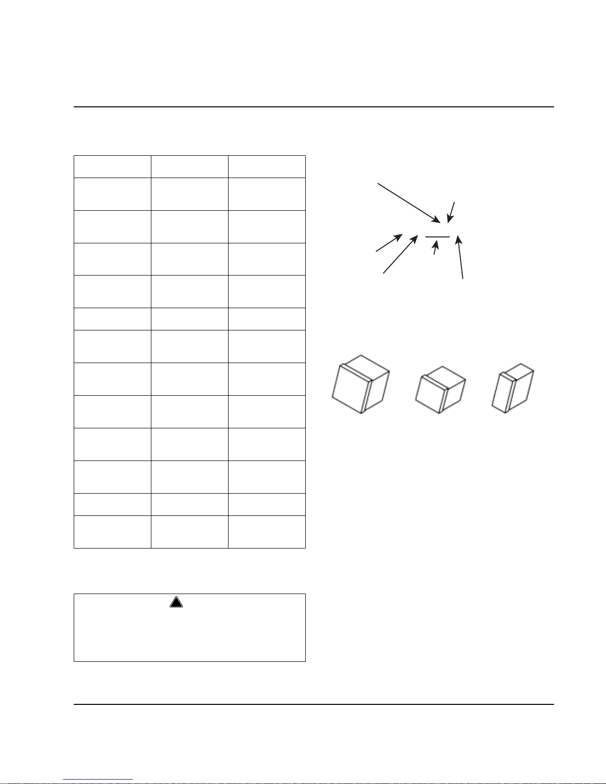
Ice Cube Sizes
Self-Contained
Air-Cooled
Self-Contained
Water-Cooled
Remote
QR0320A
QD0322A
QY0324A
QR0321W
QD0323W
QY0325W
--
--
QR0420A
QD0422A
QY0424A
QR0421W
QD0423W
QY0425W
--
--
QR0200A
QD0202A
QY0204A
QR0201W
QD0203W
QY0205W
--
--
QR0280A
QD0282A
QY0284A
QR0281W
QD0283W
QY0285W
--
--
QD0372A
QY0374A
QD0373W
QY0375W
--
--
QR0450A
QD0452A
QY0454A
QR0451W
QD0453W
QY0455W
QR0490N
QD0492N
QY0494N
QR0600A
QD0602A
QY0604A
QR0601W
QD0603W
QY0605W
QR0690N
QD0692N
QY0694N
QR0800A
QD0802A
QY0804A
QR0801W
QD0803W
QY0805W
QR0890N
QD0892N
QY0894N
QR1000A
QD1002A
QY1004A
QR1001W
QD1003W
QY1005W
QR1090N
QD1092N
QY1094N
QR1300A
QD1302A
QY1304A
QR1301W
QD1303W
QY1305W
QR1390N
QD1392N
QY1394N
--
--
QD1603W
QY1605W
QD1692N
QY1694N
QR1800A
QD1802A
QY1804A
QR1801W
QD1803W
QY1805W
QR1890N
QD1892N
QY1894N
!
Warning
PERSONAL INJURY POTENTIAL
Do not operate equipment that has been misused,
abused, neglected, damaged, or altered/modified
from that of original manufactured specifications.
Regular
1-1/8" x 1-1/8" x 7/8"
2.86 x 2.86 x 2.22 cm
Dice
7/8" x 7/8" x 7/8"
2.22 x 2.22 x 2.22 cm
Half Dice
3/8" x 1-1/8" x 7/8"
0.95 x 2.86 x 2.22 cm
Q R 0450 A
ICE M A CHINE
MODEL
ICE CUBE SIZE
R REG ULAR
D DICE
Y HALF DICE
# C UB E SIZE
0 REG ULAR
1 R E G U L AR
2 DICE
3 DICE
4 H A LF-DICE
5 H A LF-DICE
CONDEN SER TY PE
AIR-COOLED
W ATER-COOLED
AIR-COOLED
W ATER-COOLED
AIR-COOLED
W ATER-COOLED
A SELF-CON TAINED AIR-COOLED
W SELF-CON TAINED W ATER-COOLED
N REMO TE AIR-COOLED
9 REMO TE
AIR-COOLED
CONDEN SER TY PE
ICE M A CHINE
SERIES
Page 12
General Information Section 1
1-2 Part No. 80-1100-3
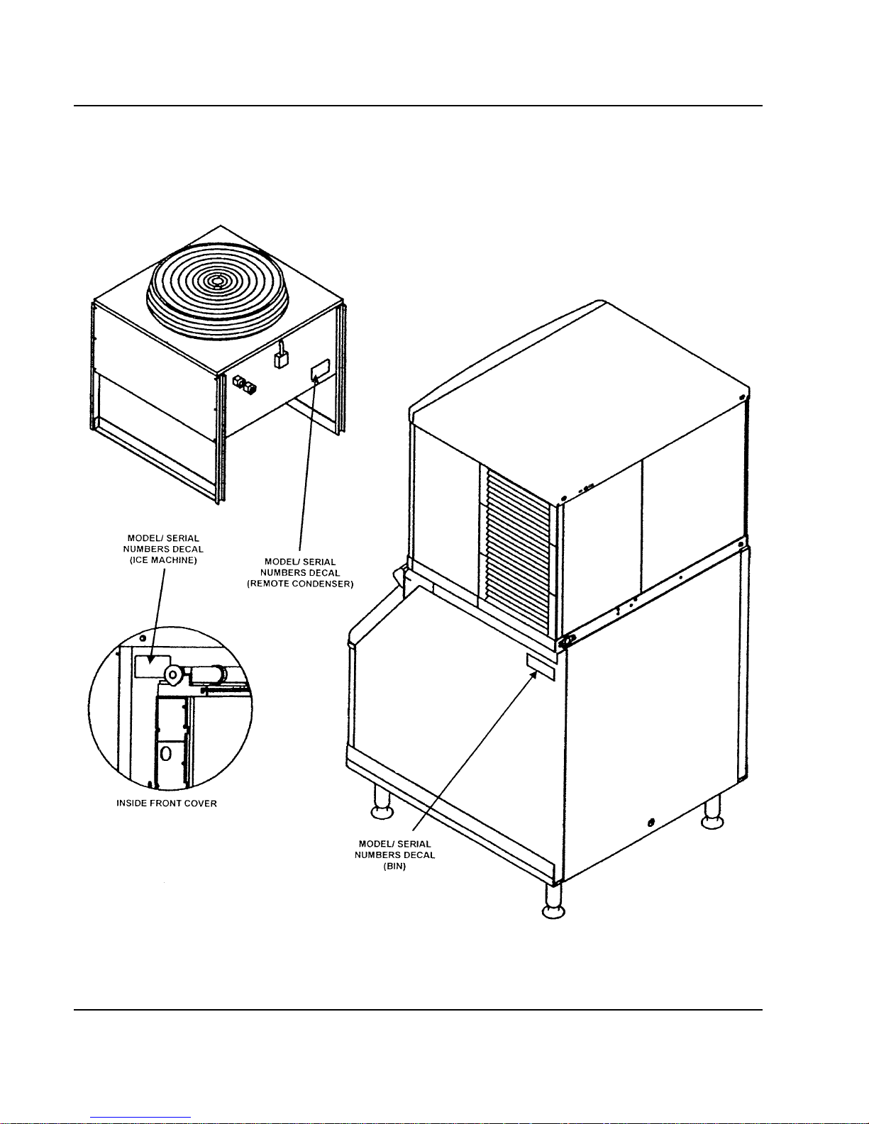
Model/Serial Number Location
These numbers are required when requesting
information from your local Manitowoc distributor, or
Manitowoc Ice, Inc.
The model and serial number are listed on the MODEL/
SERIAL NUMBER DECAL affixed to the ice machine,
remote condenser and storage bin.
Figure 1-1. Model/Serial Number Location
SV1600
Page 13

Section 1 General Information
Part No. 80-1100-3 1-3
Warranty Coverage
GENERAL
The following Warranty outline is provided for your
convenience. For a detailed explanation, re ad the
warranty bond shipped with each product.
Contact your local Manitowoc Distributor or Manitowoc
Ice, Inc. if you need further warranty information.
PARTS
1. Manitowoc warrants the ice machine against defects
in materials and workmanship, under normal use
and service for three (3) years from the date of
original installation.
2. The evaporator and compressor are covered by an
additional two (2) year (five years total) warranty
beginning on the date of the original installation.
LABOR
1. Labor required to repair or replace defective
components is covered for three (3) years from the
date of original installation.
2. The evaporator is covered by an additional two (2)
year (five years total) labor warranty beginning on
the date of the original installation.
EXCLUSIONS
The following items are not included in the ice machine’s
warranty coverage:
1. Normal maintenance, adjustments and cleaning.
2. Repairs due to unauthorized modifications to the ice
machine or use of non-standard parts without prior
written approval from Manitowoc Ice, Inc.
3. Damage caused by improper installation of the ice
machine, electrical supply , water supply or drainage,
or damage caused by floods, storms, or other acts of
God.
4. Premium labor rates due to holidays, overtime,
etc.; travel time; flat rate service call charges;
mileage and miscellaneous tools and material
charges not listed on the payment schedule.
Additional labor charges resulting from the
inaccessibility of equipment are also excluded.
5. Parts or assemblies subjected to misuse, abuse,
neglect or accidents.
6. Damage or problems caused by installation,
cleaning and/or maintenance procedures
inconsistent with the technical instructions provided
in this manual.
7. This product is intended exclusively for commercial
application. No warranty is extended for personal,
family, or household purposes.
AUTHORIZED WARRANTY SERVICE
To comply with the provisions of the warranty, a
refrigeration service company qualified and authorized
by a Manitowoc distributor, or a Contracted Service
Representative must perform the warranty repair.
Important
This product is intended exclusively for commercial
application. No warranty is extended for personal,
family, or household purposes.
Page 14

General Information Section 1
1-4 Part No. 80-1100-3
THIS PAGE INTENTIONALLY LEFT BLANK
Page 15
Part No. 80-1100-3 2-1
Section 2
Installation Instructions
General
Refer to Installation Manual for complete installation
guidelines.
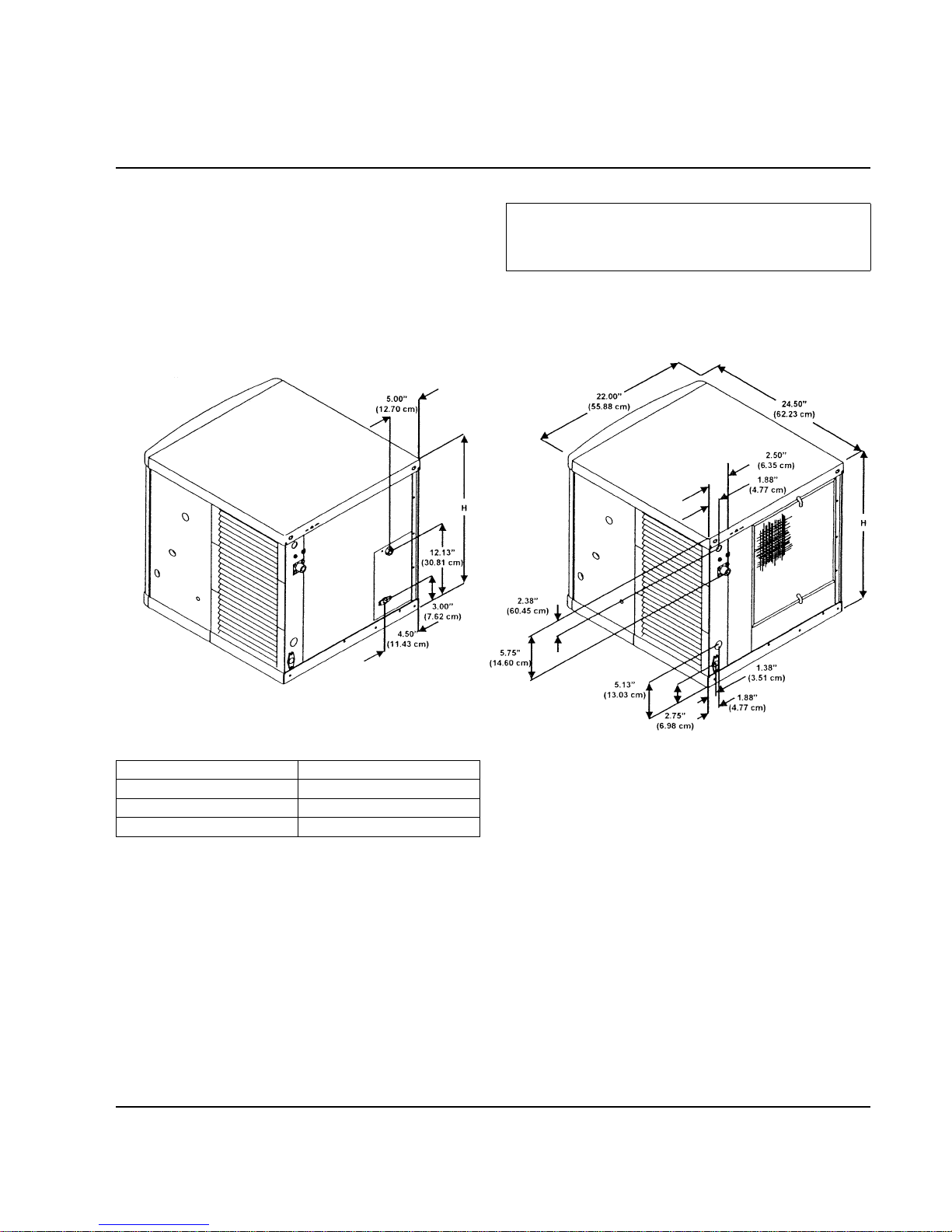
Ice Machine Dimensions
Q320/Q370/Q420 ICE MACHINES
Important
Failure to follow these installation guidelines may
affect warranty coverage.
SV1602 SV1611
WATER COOLED AIR COOLED
Ice Machine Dimension H
Q320 21.5 in (54.6 cm)
Q370 21.5 in (54.6 cm)
Q420 26.5 in (67.3 cm)
Page 16
Installation Instructions Section 2
2-2 Part No. 80-1100-3
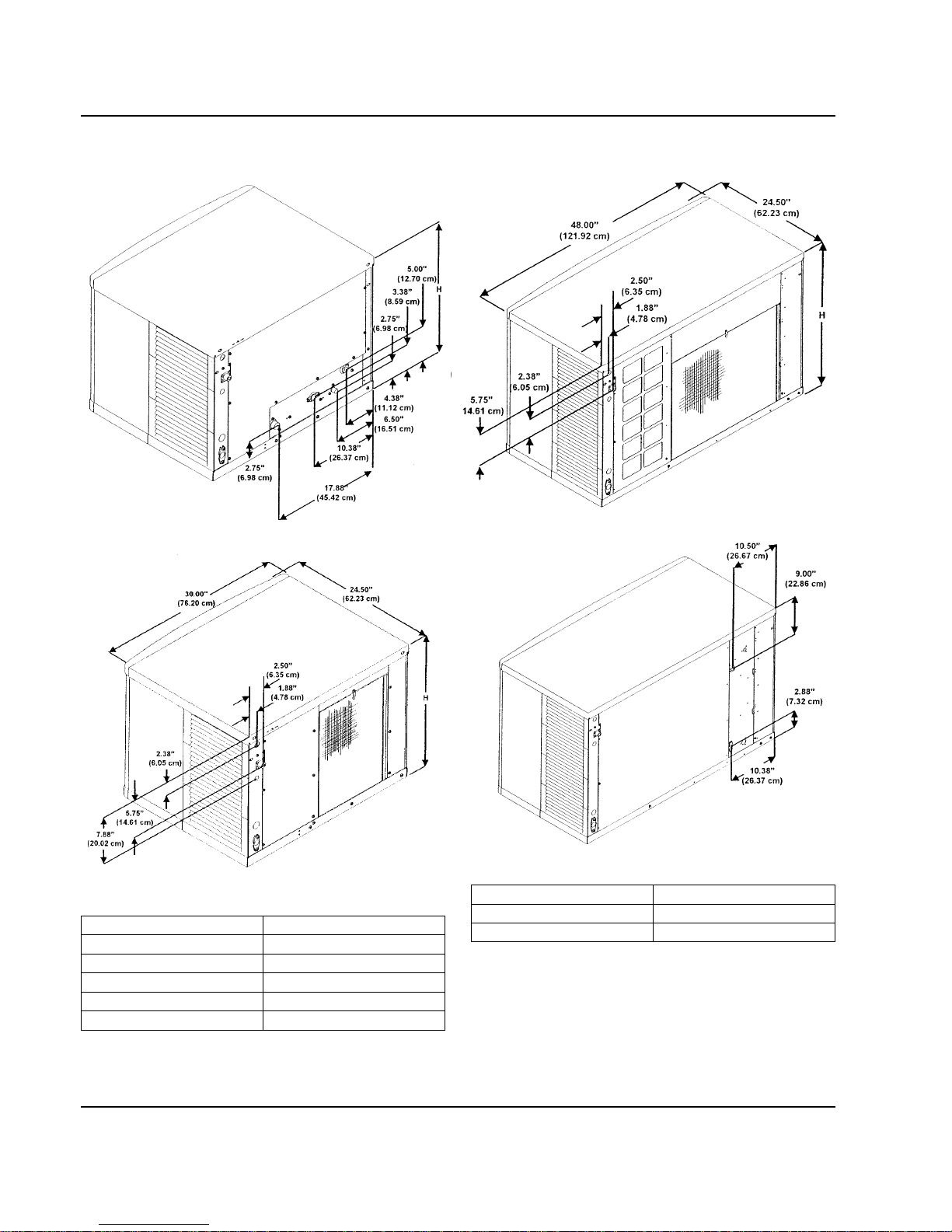
Q200 – Q1000 ICE MACHINES Q1300/Q1600/Q1800 ICE MACHINES
SV1612 SV1628
WATER-COOLED SELF CONTAINED
AIR-COOLED
Ice Machine Dimension H
Q200 – Q280 16.5 in (41.9 cm)
Q450 21.5 in (54.6 cm)
Q600 21.5 in (54.6 cm)
Q800 26.5 in (67.3 cm)
Q1000 29.5 in (74.9 cm)
SV1613
AIR-COOLED
Ice Machine Dimension H
Q1300/Q1600 29.5 in (74.9 cm)
Q1800 29.5 in (74.9 cm)
SV1627
SELF CONTAINED
WATER-COOLED
Page 17
Section 2 Installation Instructions
Part No. 80-1100-3 2-3
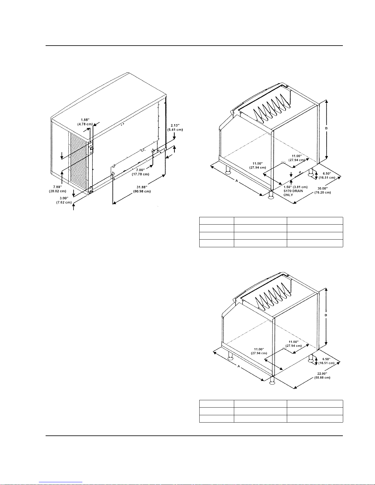
Q1300/Q1600/Q1800 ICE MACHINES (CONT.)
Ice Storage Bin Dimensions
S170/S400/S570 ICE STORAGE BINS
S320/S420 ICE STORAGE BINS
SV1629
REMOTE AIR-COOLED
Bin Model Dimension A Dimension B
S170 29.5 in (74.9 cm) 19.1 in (48.5 cm)
S400 34.0 in (86.3 cm) 32.0 in (81.3 cm)
S570 34.0 in (86.3 cm) 44.0 in (111.7 cm)
Bin Model Dimension A Dimension B
S320 34.0 in (86.3 cm) 32.0 in (81.3 cm)
S420 34.0 in (86.3 cm) 44.0 in (111.7 cm)
SV1609
SV1614
Page 18
Installation Instructions Section 2
2-4 Part No. 80-1100-3
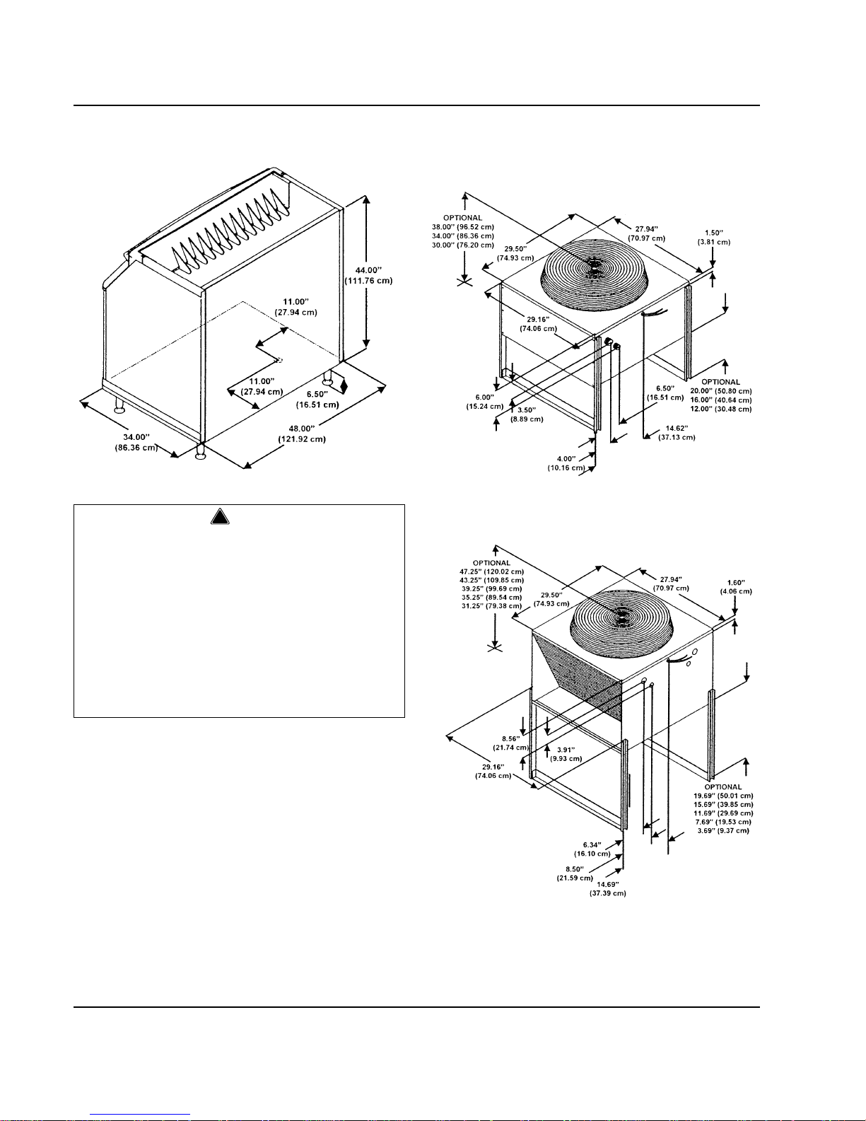
S970 ICE STORAGE BINS
Remote Condenser Dimensions
JC0495/JC0895/JC1095/JC1395
JC1895
!
Warning
All Manitowoc ice machines require the ice storage
system (bin, dispenser, etc.) to incorporate an ice
deflector.
The Q1300, Q1600 and Q1800 series ice machines
require adding Manitowoc Ice Deflector Kit K 00139
when installing with non-Manitowoc ice storage
systems.
Prior to using a non-Manitowoc ice storage system
with other Manitowoc ice machines, contact the
manufacturer to assure their ice deflector is
compatible with Manitowoc ice machines.
SV1610 SV1297
SV1301
Page 19
Section 2 Installation Instructions
Part No. 80-1100-3 2-5
Location of Ice Machine
The location selected for the ice machine must meet the
following criteria. If any of these criteria are not met,
select another location.
• Th e location must be free of airborne and other
contaminants.
• The air temperature must be at least 35°F (1.6°C),
but must not exceed 110°F (43.4°C).
• The location must not be near heat-generating
equipment or in direct sunlight.
• The location must not obstruct air flow through or
around the ice machine. Refer to the chart below for
clearance requirements.
Stacking Two Ice Machines on a Single
Storage Bin
A stacking kit is required for stacking two ice machines.
Installation instructions are supplied with the stacking kit.
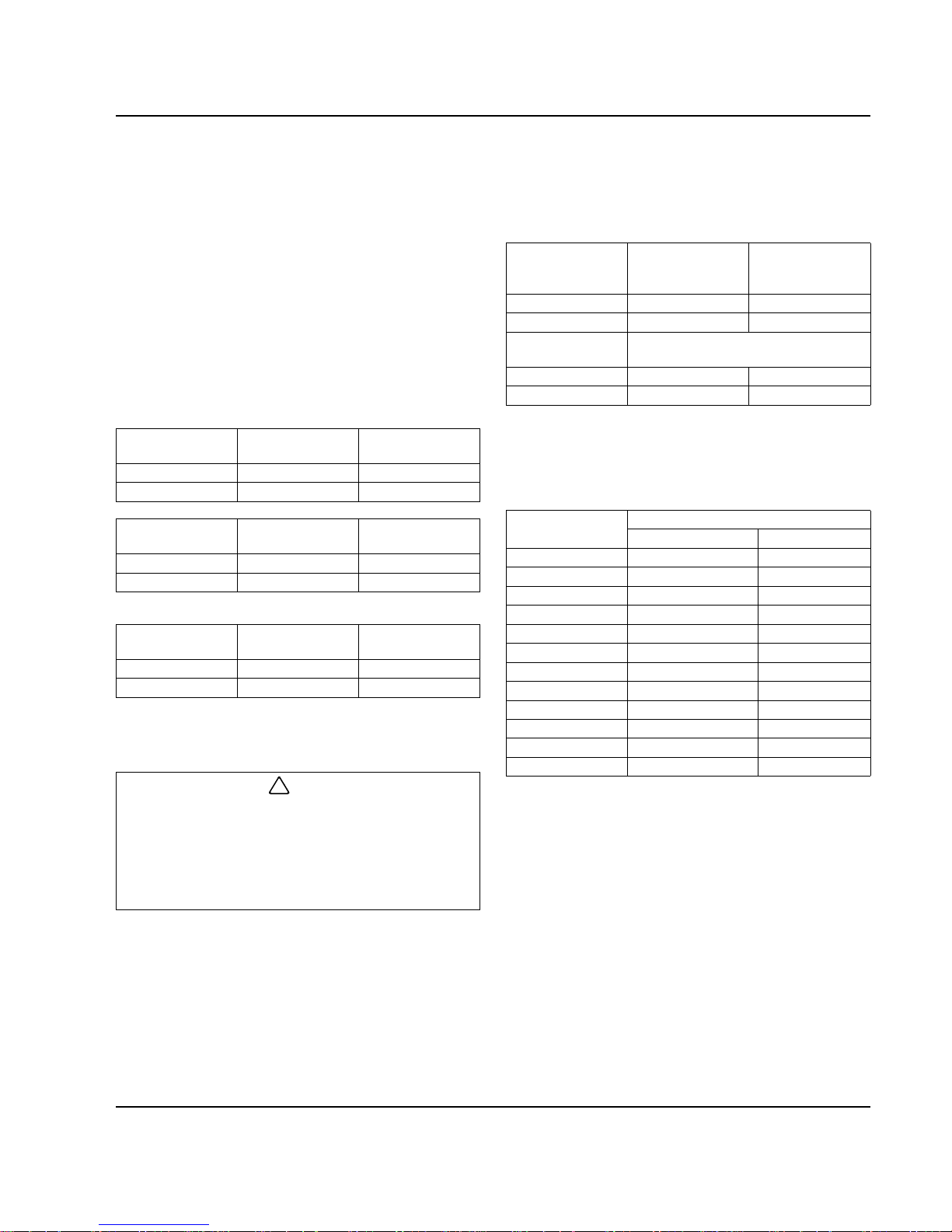
Ice Machine Heat of Rejection
Ice machines, like other refrigeration equipment, reject
heat through the condenser. It is helpful to know the
amount of heat rejected by the ice machine when sizing
air conditioning equipment where self-contained aircooled ice machines are installed.
This information is also necessary when evaluating the
benefits of using water-cooled or remote condensers to
reduce air conditioning loads. The amount of heat added
to an air conditioned environment by an ice machine
using a water-cooled or remote condenser is negligible.
Knowing the amount of heat rejected is also important
when sizing a cooling tower for a water-cooled
condenser. Use the peak figure for sizing the cooling
tower.
Q1300/Q1600/
Q1800
Self-Contained
Air-Cooled
Water-Cooled
and Remote
Top/Sides 24" (61 cm) 8" (20.3 cm)
Back 12" (30.5 cm) 5" (12.7 cm)
Q370
Self-Contained
Air-Cooled
Water-Cooled
Top/Sides 12" (30.5 cm) 5" (12.7 cm)
Back 5" (127 mm) 5" (12.7 cm)
All other
Q models
Self-Contained
Air-Cooled
Water-Cooled
and Remote
Top/Sides 8" (20.3 cm) 8" (20.3 cm)
Back 5" (12.7 cm) 5" (12.7 cm)
There is no minimum clearance required. This value is
recommended for efficient operation and servicing only.
Q1600 is not available as an air-cooled model.
!
Caution
The ice machine must be protected if it will be
subjected to temperatures below 32°F (0°C).
Failure caused by exposure to freezing
temperatures is not covered by the warranty. See
“Removal from Service/Winterization” on Page 3-
14.
Q450/Q600/
Q800/Q1000
Stacked
Self-Contained
Air-Cooled
Stacked
Water-Cooled
and Remote*
Top/Sides 16" (40.64 cm) 5" (12.70 cm)
Back 5" (12.70 cm) 5" (12.70 cm)
Q1300/Q1600/
Q1800
Top/Sides 48" (121.92 cm) 24" (60.96 cm)
Back 12" (30.48 cm) 12" (30.48 cm)
*There is no minimum clearance required. This value is
recommended for efficient operation and servicing only.
Q1600 is not available as an air-cooled model.
Series
Ice Machine
Heat of Rejection
B.T.U./Hour
Air Conditioning
Because the heat of rejection varies during the ice making cycle,
the figure shown is an average.
Peak
Q320 4,600 6,200
Q370 3,900 5,950
Q420 7,000 9,600
Q200 3,800 5,000
Q280 3,800 6,000
Q450 7,000 9,600
Q600 9,000 13,900
Q800 12,400 19,500
Q1000 16,000 24,700
Q1300 24,000 35,500
Q1600 24,000 35,500
Q1800 36,000 50,000
Page 20
Installation Instructions Section 2
2-6 Part No. 80-1100-3
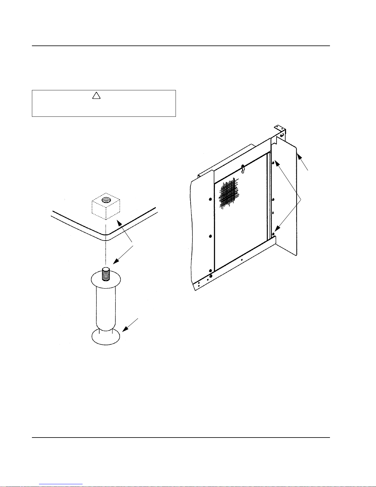
Leveling the Ice Storage Bin
1. Screw the leveling legs onto the bottom of the bin.
2. Screw the foot of each leg in as far as possible.
3. Move the bin into its final position.
4. Level the bin to assure that the bin door closes and
seals properly. Use a level on top of the bin. Turn
each foot as necessary to level the bin.
NOTE: An optional caster assembly is available for use
in place of the legs. Installation instructions are supplied
with the casters.
Figure 2-1. Leveling Leg and Foot
Air-Cooled Baffle
The air-cooled baffle prevents condenser air from
recirculating. To install:
1. Remove the back panel screws next to the
condenser.
2. Align the mounting holes in the air baffle with the
screw holes and reinstall the screws.
Figure 2-2. Air Baffle
!
Caution
The legs must be screwed in tightly to prevent them
from bending.
SV1606
THREAD LEVELING
LEG INTO BASE OF
CABINET
THREAD ‘FOOT’ IN AS
FAR AS POSSIBLE
SV1607
AIR
BAFFLE
SCREWS
Page 21
Section 2 Installation Instructions
Part No. 80-1100-3 2-7
Electrical Service
GENERAL
VOLTAGE
The maximum allowable voltage variation is ±1 0% of the
rated voltage at ice machine start-up (wh en the electrical
load is highest).
FUSE/CIRCUIT BREAKER
A separate fuse/circuit breaker must be provided for
each ice machine. Circuit breakers must be H.A.C.R.
rated (does not apply in Canada).
MINIMUM CIRCUIT AMPACITY
The minimum circuit ampacity is used to help select the
wire size of the electrical supply. (Minimum circuit
ampacity is not the ice machine’s running amp load.)
The wire size (or gauge) is also dependent upon
location, materials used, length of run, etc., so it must be
determined by a qualified electrician.
!
Warning
All wiring must conform to local, state and national
codes.
!
Warning
The ice machine must be grounded in accordance
with national and local electrical codes.
Page 22
Installation Instructions Section 2
2-8 Part No. 80-1100-3
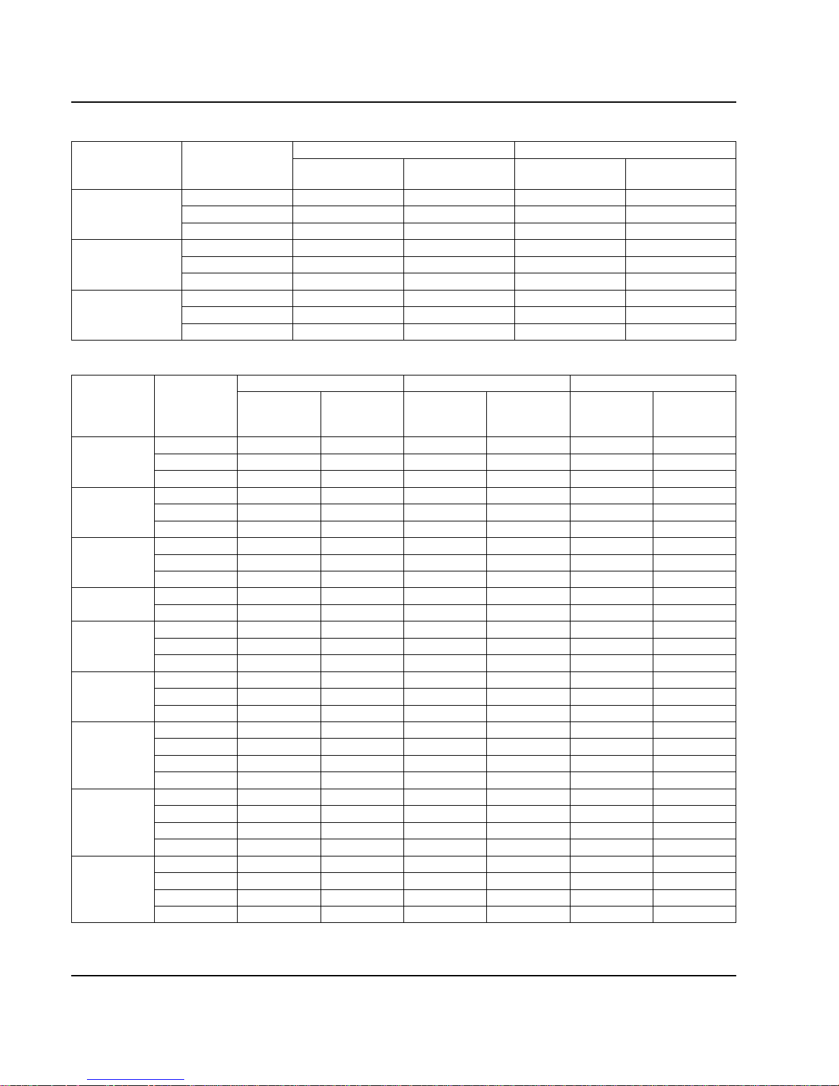
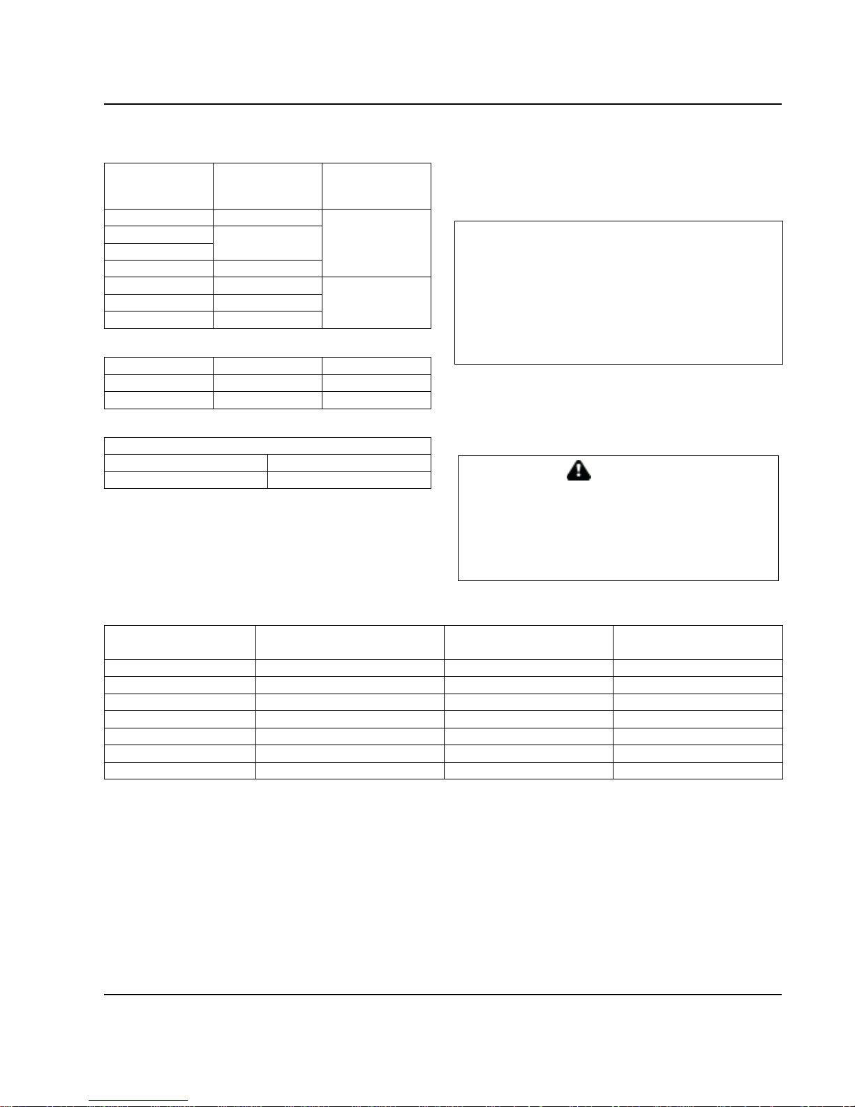
Table 2-1. Q320/370/420 Ice Machines
Table 2-2. Q200 - Q1000 Ice Machines
Ice Machine
Voltage
Phase
Cycle
Air-Cooled Water Cooled
Maximum Fuse/
Circuit Breaker
Minimum
Circuit Amps
Maximum Fuse/
Circuit Breaker
Minimum
Circuit Amps
Q320
115/1/60 15 11.2 15 10.5
208-230/1/60 15 4.8 15 4.2
230/1/50 15 5.2 15 4.7
Q370
115/1/60 20 12.9 20 12.2
208-230/1/60 15 6.2 15 5.8
230/1/50 15 6.2 15 5.8
Q420
115/1/60 20 12.3 20 11.4
208-230/1/60 15 7.8 15 7.4
230/1/50 15 6.3 15 5.9
Ice Machine
Voltage
Phase
Cycle
Air-Cooled Water Cooled Remote
Maximum
Fuse/Circuit
Breaker
Minimum
Circuit Amps
Maximum
Fuse/Circuit
Breaker
Minimum
Circuit Amps
Maximum
Fuse/Circuit
Breaker
Minimum
Circuit Amps
Q200
115/1/60 15 11.6 15 10.9 N/A N/A
208-230/1/60 15 5.4 15 4.8 N/A N/A
230/1/50 15 5.2 15 4.9 N/A N/A
Q280
115/1/60 20 12.6 20 11.7 N/A N/A
208-230/1/60 15 5.7 15 5.2 N/A N/A
230/1/50 15 5.7 15 5.2 N/A N/A
Q450
115/1/60 20 12.8 20 11.9 20 13.6
208-230/1/60 15 7.8 15 7.4 N/A N/A
230/1/50 15 6.1 15 5.7 N/A N/A
Q600
208-230/1/60 15 9.2 15 8.7 15 9.3
230/1/50 15 9.2 15 8.8 15 9.4
Q800
208-230/1/60 20 12.1 20 11.4 20 11.9
208-230/3/60 15 8.9 15 8.2 15 8.9
230/1/50 20 12.0 20 10.6 20 11.2
Q1000
208-230/1/60 20 14.3 20 13.2 20 14.2
208-230/3/60 15 9.8 15 8.8 15 9.9
230/1/50 20 15.6 20 14.2 20 14.6
Q1300
208-230/1/60 30 19.5 30 18.1 30 19.8
208-230/3/60 20 13.1 20 11.6 20 12.7
230/1/50 30 15.7 30 14.3 30 14.7
380-415/3/50 N/A N/A N/A N/A 15 7.3
Q1600
208-230/1/60 N/A N/A 30 17.2 30 18.2
208-230/3/60 N/A N/A 20 11.0 20 12.0
230/1/50 N/A N/A N/A N/A N/A N/A
380-415/3/50 N/A N/A N/A N/A N/A N/A
Q1800
208-230/1/60 40 28.1 40 26.7 40 26.9
208-230/3/60 20 15.5 20 14.1 20 13.9
230/1/50 40 23.3 40 21.9 40 22.2
380-415/3/50 N/A N/A N/A N/A 15 9.1
Page 23
Section 2 Installation Instructions
Part No. 80-1100-3 2-9
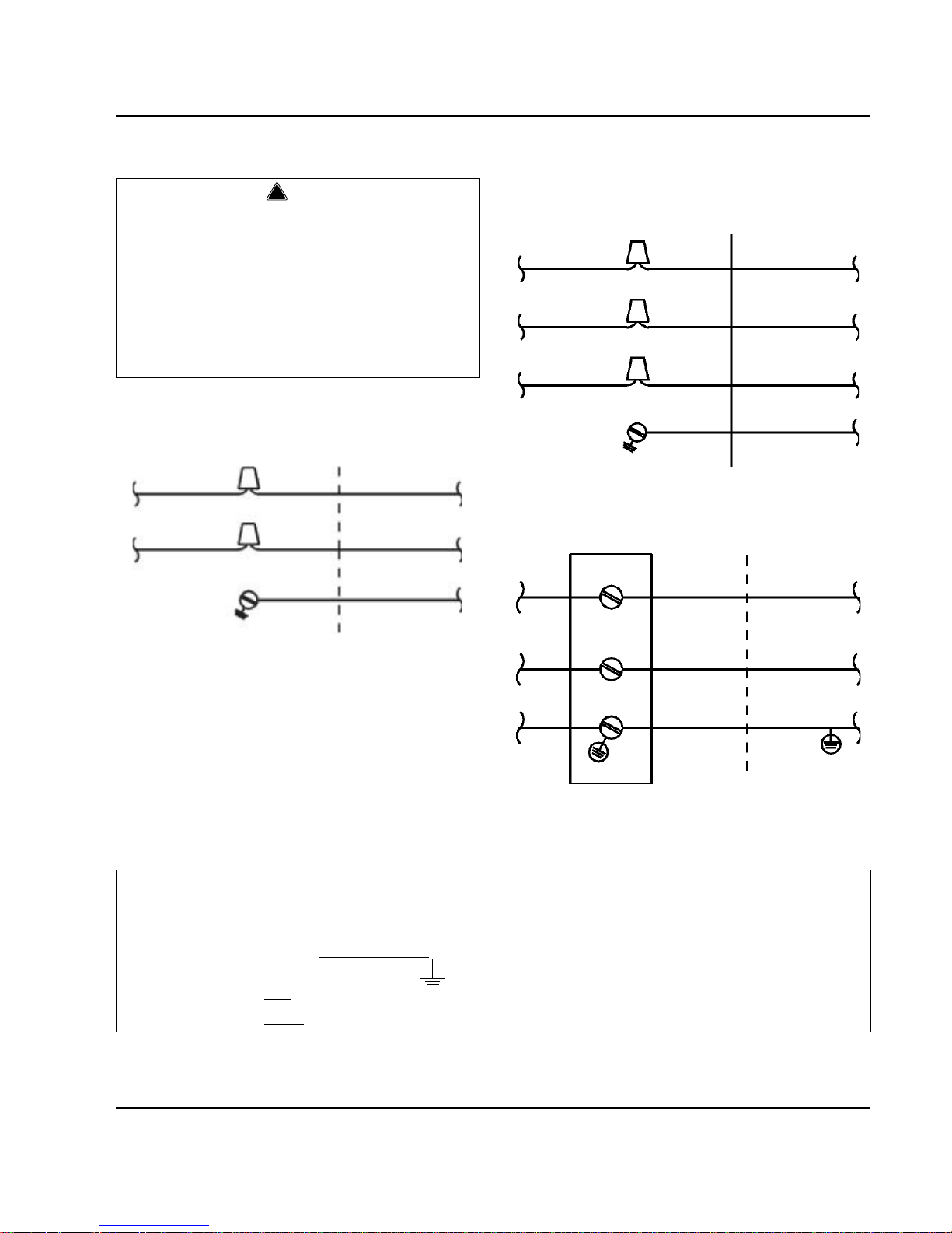
Self-Contained Electrical Wiring Connections
SELF CONTAINED ICE MACHINE
115/1/60 OR 208-230/1/60
SELF CONTAINED ICE MACHINE
208-230/3/60
SELF CONTAINED ICE MACHINE
230/1/50
!
Warning
These diagrams are not intended to show proper
wire routing, wire sizing, disconnects, etc., only the
correct wire connections.
All electrical work, including wire routing and
grounding, must conform to local, state and national
electrical codes.
Though wire nuts are shown in the drawings, the ice
machine field wiring connections may use either
wire nuts or screw terminals.
L
1
L
1
N=115V
OR
L2=208-230V
GROUND
GROUND
ICE MACHINE
CONNECTIONS
SV1258
L
1
L
1
GROUND
GROUND
ICE MACHINE
CONNECTIONS
TO SEPARATE
FUSE/BREAKER
L
2
L
3
L
2
L
3
SV1190
L
1
L
1
N
N
GROUND
GROUND
ICE MACHINE
CONNECTIONS
TO SEPARATE
FUSE/BREAKER.
DISCONNECT ALL
POLES.
SV1191
For United Kingdom Only
As the colours of the wires in the mains lead of the appliance may not correspond with the coloured markings
identifying the terminals in your plug, proceed as follows:
• The wire which is colour ed green and yello w
must be connected to the terminal in the plug which is marked with
the letter E or by the earth ground symbol or coloured green or green and yellow.
• The wire coloured blue
must be connected to the terminal which is marked with the letter N or coloured black.
• The wire coloured brown
must be connected to the terminal which is marked with the letter L or coloured red.
TO SEPARATE
FUSE/BREAKER
Page 24
Installation Instructions Section 2
2-10 Part No. 80-1100-3
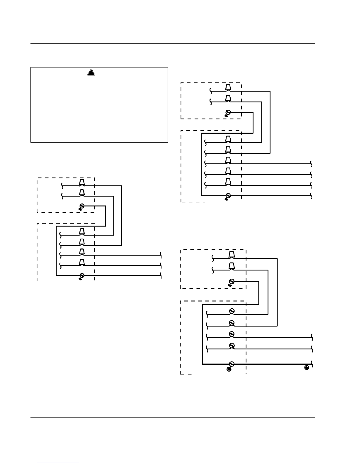
Remote Electrical Wiring Connections
REMOTE ICE MACHINE
WITH SINGLE CIRCUIT MODEL CONDENSER
115/1/60 OR 208-230/1/60
REMOTE ICE MACHINE
WITH SINGLE CIRCUIT MODEL CONDENSER
208-230/3/60 OR 380-415/3/50
REMOTE ICE MACHINE
WITH SINGLE CIRCUIT MODEL CONDENSER
230/1/50
!
Warning
These diagrams are not intended to show proper
wire routing, wire sizing, disconnects, etc., only the
correct wire connections.
All electrical work, including wire routing and
grounding, must conform to local, state and national
electrical codes.
Though wire nuts are shown in the drawings, the ice
machine field wiring connections may use either
wire nuts or screw terminals.
L
1
NOTE:
CONDENSER FAN
MOTOR VOLTAGE
MATCHES ICE
MACHINE
VOLTAGE (115V
OR 208-230V)
GROUND
SINGLE CIRCUIT
REMOTE
CONDENSER
ICE
MACHINE
SV1255
L
2
L
1
L
2
GROUND
TO SEPARATE
FUSE/BREAKER
GROUND
L
1
L
2
F
2
F
1
N=115V OR L2=208-230V
GROUND
ICE
MACHINE
SV1199
L
3
L
1
L
2
GROUND
TO SEPARATE
FUSE/BREAKER
GROUND
L
3
L
1
L
2
F
2
F
1
NOTE: FAN
MOTOR IS
208-230V
L
1
L
2
SINGLE CIRCUIT
REMOTE
CONDENSER
SINGLE CIRCUIT
REMOTE
CONDENSER
L
1
L
2
NOTE: FAN
MOTOR IS
220-240V
L
1
N
F
2
F
1
ICE
MACHINE
GROUND
L
1
N
GROUND
TO SEPARATE
FUSE/BREAKER
(220-240).
DISCONNECT ALL
POLES.
SV1256
Page 25

Section 2 Installation Instructions
Part No. 80-1100-3 2-11
Water Supply and Drain Requirements
WATER SUPPLY
Local water conditions may require treatment of the
water to inhibit scale formation, filter sediment, and
remove chlorine odor and taste.
WATER INLET LINES
Follow these guidelines to install water inlet lines:
• Do not connect the ice machine to a hot water
supply. Be sure all hot water restrictors installed for
other equipment are working. (Check valves on sink
faucets, dishwashers, etc.)
• If water pressure exceeds the maximum
recommended pressure, obtain a water pressure
regulator from your Manitowoc distributor.
• I nstall a water shut-off valve for both the ice making
and condenser water lines.
• Insulate water inlet lines to prevent condensation.
DRAIN CONNECTIONS
Follow these guidelines when installing drain lines to
prevent drain water from flowing back into the ice
machine and storage bin:
• Drain lines must have a 1.5 inch drop per 5 feet of
run (2.5 cm per meter), and must not create traps.
• The floor drain must be large enough to
accommodate drainage from all drains.
• Run separate bin and ice machine drain lines.
Insulate them to prevent condensation.
• Vent the bin and ice machine drain to the
atmosphere. Do not vent the condenser drain on
water-cooled models.
Cooling Tower Applications
(Water-Cooled Models)
A water cooling tower installation does not require
modification of the ice machine. The water regulator
valve for the condenser continues to control the
refrigeration discharge pressure.
It is necessary to know the amount of heat rejection, a nd
the pressure drop through the condenser and water
valves (inlet and outlet) when using a cooling tower on
an ice machine.
• Water entering the condenser must not exceed 90°F
(32.2°C).
• Water flow through the condense r must not exceed 5
gallons (19 liters) per minute.
• Allow for a pressure drop of 7 psi (48 kPA) between
the condenser water inlet and the outlet of the ice
machine.
• Water exiting the condenser must not exceed 110°F
(43.3°C).
Important
If you are installing a Manitowoc water filter system,
refer to the Installation Instructions supplied with the
filter system for ice making water inlet connections.
Page 26
Installation Instructions Section 2
2-12 Part No. 80-1100-3
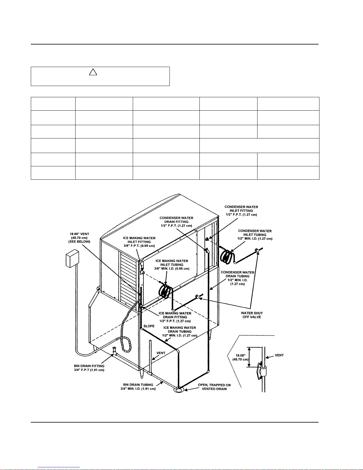
WATER SUPPLY AND DRAIN LINE SIZING/CONNECTIONS
Figure 2-3. Typical Water Supply Drain Installation
!
Caution
Plumbing must conform to state and local codes.
Location Water Temperature Water Pressure Ice Machine Fitting
Tubing Size Up to Ice
Machine Fitting
Ice Making
Water Inlet
33°F (0.6°C) Min.
90°F (32.2°C) Max.
20 psi (137.9 kPA) Min.
80 psi (551.5 kPA) Max.
3/8" Female
Pipe Thread
3/8" (9.5 mm) minimum
inside diameter
Ice Making
Water Drain
--- ---
1/2" Female
Pipe Thread
1/2" (12.7 mm) minimum
inside diameter
Condenser
Water Inlet
33°F (0.6°C) Min.
90°F (32.2°C) Max.
20 psi (137.9 kPA) Min.
150 psi (1034.2 kPA) Max.
Q1300/Q1600/Q1800 - 1/2" Female Pipe Thread
All Others - 3/8" Female Pipe Thread
Condenser
Water Drain
--- ---
1/2" Female
Pipe Thread
1/2" (12.7 mm) minimum
inside diameter
Bin Drain --- ---
3/4" Female
Pipe Thread
3/4" (19.1 mm) minimum
inside diameter
SV1626
Page 27
Section 2 Installation Instructions
Part No. 80-1100-3 2-13
Remote Condenser/Line Set Installation
REMOTE ICE MACHINES
REFRIGERANT CHARGE
Each remote ice machine ships from the factory with a
refrigerant charge appropriate for installation with line
sets of up to 50' (15.25 m). The serial tag on the ice
machine indicates the refrigerant charge.
Additional refrigerant may be required for installations
using line sets between 50' and 100' (15.25-30.5 m)
long. If additional refrigerant is required, an additional
label located next to the Model/Serial Numbers decal
states the amount of refrigerant to be added.
Figure 2-4. Typical Additional Refrigerant Label
If there is no additional label, the nameplate charge is
sufficient for line sets up to 100' ( 30.5 m). ( See the ch art
below.)
Ice Machine
Remote Single
Circuit
Condenser
Line Set*
Q490 JC0495 RT-20-R404A
RT-35-R404A
RT-50-R404A
Q690 JC0895
Q890
Q1090 JC1095
Q1390 JC1395 RL-20-R404A
RL-35-R404A
RL-50-R404A
Q1690 JC1695
Q1890 JC1895
*Line Set Discharge Line Liquid Line
RT 1/2" (1.27 cm) 5/16" (.79 cm)
RL 1/2" (1.27 cm) 3/8" (.95 cm)
Air Temperature Around the Condenser
Minimum Maximum
-20°F (-28.9°C) 120°F (49°C)
IMPORTANT
EPA CERTIFIED TECHNICIANS
If remote line set length is between 50' and 100' (15.25-
30.5 m), add
1.5 lb. (24 oz) (0.68 kg) of refrigerant to the
nameplate charge.
Tubing length: ______________________________
Refrigerant added to nameplate: ________________
New total refrigerant charge: ___________________
WARNING
Potential Personal Injury Situation
The ice machine contains refrigerant charge. Installation of
the line sets must be performed by a properly trained and
EPA certified refrigeration technician aware of the dangers
of dealing with refrigerant charged equipment.
Ice Machine
Nameplate Charge
(Charge Shipped in Ice Machine)
Refrigerant to be Added for
50'-100' Line Sets
Maximum System Charge
(Never Exceed)
Q490 6 lb. (96 oz.) None 6 lb. (96 oz.)
Q690 8 lb. (128 oz.) None 8 lb. (128 oz.)
Q890 8 lb. (128 oz.) None 8 lb. (128 oz.)
Q1090 9.5 lb. (152 oz.) None 9.5 lb. (152 oz.)
Q1390 12.5 lb. (200 oz.) 1.5 lb. (24 oz) 14 lb. (224 oz.)
Q1690 15 lb. (240 oz.) 2.0 lb. (32 oz) 17 lb. (272 oz.)
Q1890 15 lb. (240 oz.) 2.0 lb. (32 oz) 17 lb. (272 oz.)
Page 28

Installation Instructions Section 2
2-14 Part No. 80-1100-3
GENERAL
Condensers must be mounted horizontally with the fan
motor on top.
Remote condenser installations consist of vertical and
horizontal line sets between the ice machine and the
condenser. When combin ed, they must fit within
approved specifications. The following guidelines,
drawings and calculation methods must be followed to
verify a proper remote condenser installation.
GUIDELINES FOR ROUTING LINE SETS
First, cut a 2.5" (6.35 cm) circular hole in the wall or ro of
for tubing routing. The line set end with the 90° bend will
connect to the ice machine. The straight end will connect
to the remote condenser.
Follow these guidelines when routing the refrigerant
lines. This will help insure proper performance and
service accessibility.
1. Optional - Make the service loop in the line sets (See
Figure 2-5). This permits easy access to the ice
machine for cleaning and service. Do not use hard
rigid copper at this location.
2. Required - Do not form traps in the refrigeration lines
(except the service loop). Refrigerant oil must be
free to drain toward the ice machine or the
condenser. Route excess tubing in a supported
downward horizontal spiral (See Figure 2-5). Do not
coil tubing vertically.
3. Required - Keep outdoor refrigerant line runs as
short as possible.
Figure 2-5. Routing Line Sets
!
Caution
The 60 month compressor warranty (including the
36 month labor replacement warranty) will not apply
if the remote ice machine is not installed according
to specifications.
This warranty also will not apply if the refrigeration
system is modified with a condenser, heat reclaim
device, or other parts or assemblies not
manufactured by Manitowoc Ice, Inc., unless
specifically approved in writing by Manitowoc Ice,
Inc.
1
2
3
1
2
3
DOWNWARD
HORIZONTAL
SPIRAL
SV1204
Page 29
Section 2 Installation Instructions
Part No. 80-1100-3 2-15
CALCULATING REMOTE CONDENSER
INSTALLATION DISTANCES
Line Set Length
The maximum length is 100' (30.5 m).
The ice machine compressor must have the proper oil
return. The receiver is designed to hold a charge
sufficient to operate the ice machine in ambient
temperatures between -20°F (-28.9°C) and 120°F
(49°C), with line set lengths of up to 100' (30.5 m).
Line Set Rise/Drop
The maximum rise is 35' (10.7 m).
The maximum drop is 15' (4.5 m).
Calculated Line Set Distance
The maximum distance is 150' (45.7 m).
Line set rises, drops, horizontal runs (o r combinations of
these) in excess of the stated maximums will exceed
compressor start-up and design limits. This will cause
poor oil return to the compressor.
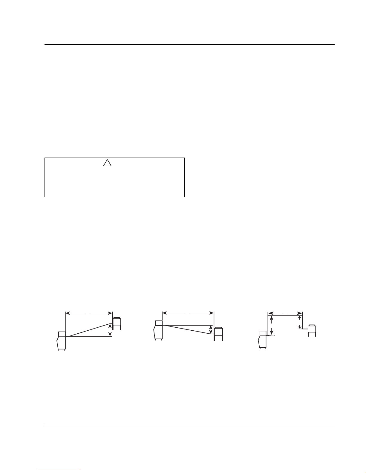
Make the following calculations to make sure the line set
layout is within specifications.
1. Insert the measured rise into the formula below.
Multiply by 1.7 to get the calculated rise.
(Example: A condenser located 10 feet above the
ice machine has a calculated rise of 17 feet.)
2. Insert the measured drop into the formula below.
Multiply by 6.6 to get the calculated drop.
(Example. A condenser located 10 feet below the
ice machine has a calculated drop of 66 feet.)
3. Insert the measured horizontal distance into the
formula below. No calculation is necessary.
4. Add together the calculated rise, calculated drop,
and horizontal d istance to get the tot al calc ulated
distance. If this total exceeds 150' (45.7 m), move
the condenser to a new location and perform the
calculations again.
Maximum Line Set Distance Formula
!
Caution
If a line set has a rise followed by a drop, another
rise cannot be made. Likewise, if a line set has a
drop followed by a rise, another drop cannot be
made.
Step 1. Measured Rise (35' [10.7 m] Maximum) ______ x 1.7 = _______ Calculated Rise
Step 2. Measured Drop (15' [4.5 m] Maximum) ______ x 6.6 = _______ Calculated Drop
Step 3. Measured Horizontal Distance (100' [30.5 m] Maximum) _______ Horizontal Distance
Step 4. Total Calculated Distance 150' (45.7 m) _______ Total Calculated Distance
H
R
H
D
H
D
R
Figure 2-6. Combination of a Rise
and a Horizontal Run
Figure 2-7. Combination of a Drop
and a Horizontal Run
Figure 2-8. Combination of a
Rise, a Drop and a Horizontal Run
SV1196 SV1195 SV1194
Page 30
Installation Instructions Section 2
2-16 Part No. 80-1100-3
LENGTHENING OR REDUCING LINE SET LENGTHS
In most cases, by routing the line set properly,
shortening will not be necessary. When shortening or
lengthening is required, do so before connecting the line
set to the ice machine or the remote condenser. This
prevents the loss of refrigerant in the ice machine or
condenser.
The quick connect fittings on the line sets are equipped
with Schraeder valves. Use these valves to recover any
vapor charge from the line set. When lengthening or
shortening lines, follow good refrigeration practices and
insulate new tubing. Do not change the tube sizes.
Evacuate the lines and place about 5 oz (143g) of vapor
refrigerant charge in each line.
CONNECTING A LINE SET
1. Remove the dust caps from the line set, condenser
and ice machine.
2. Apply refrigeration oil to the threads on the quick
disconnect couplers before connecting them to the
condenser.
3. Carefully thread the female fitting to the condenser
or ice machine by hand.
4. Tighten the coup lings with a wrench until they
bottom out.
5. Turn an additional 1/4 turn to ensure proper brassto-brass seating. Torque to the following
specifications:
6. Check all fittings for leaks.
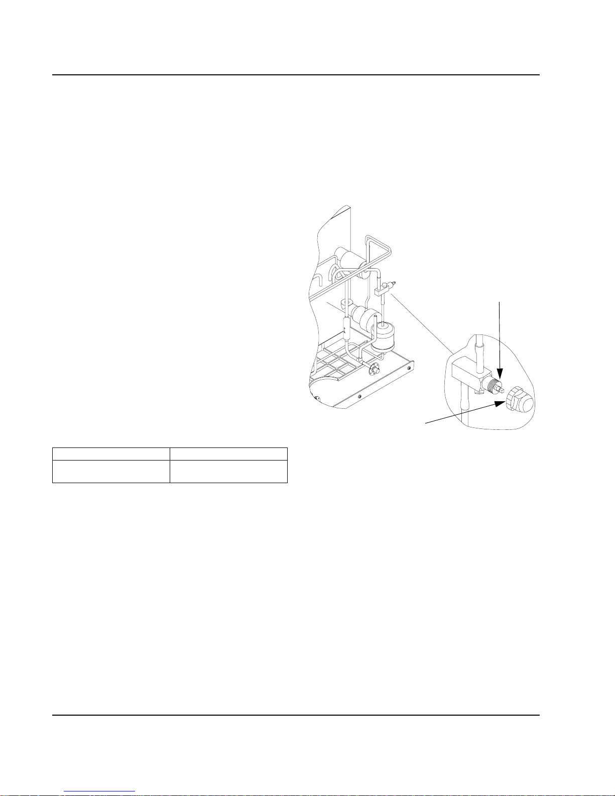
REMOTE RECEIVER SERVICE VALVE
The receiver service valve is closed during shipment.
Open the valve prior to starting the ice machine.
1. Remove the top and left side panels.
2. Remove the receiver service valve cap.
3. Backseat (open) the valve.
4. Reinstall the cap and panels.
Figure 2-9. Backseating the Receiver Service Valve
Liquid Line Discharge Line
10-12 ft lb.
(13.5-16.2 N•m)
35-45 ft lb.
(47.5-61.0 N•m)
SV1603
REMOVE FRONT, TOP,
AND LEFT SIDE PANEL
FOR ACCESS TO
RECEIVER VALVE
TURN
COUNTERCLOCKWISE TO
OPEN
RECEIVER SERVICE
VALVE CAP (TURN
COUNTERCLOCKWISE TO
REMOVE)
Page 31
Section 2 Installation Instructions
Part No. 80-1100-3 2-17
Remote Ice Machine Usage with Non-Manitowoc Multi-Circuit Condensers
WARRANTY
The sixty (60) month compressor warranty, including
thirty six (36) month labor replacement warranty, shall
not apply when the remote ice machine is not installed
within the remote specifications. The foregoing warranty
shall not apply to any ice machine installed and/or
maintained inconsistent with the technical instructions
provided by Manitowoc Ice, Inc. Performance may vary
from Sales specifications. Q-Model ARI certified
standard ratings only apply when used with a Manitowoc
remote condenser.
If the design of the condenser meets the specifications,
Manitowoc’s only
approval is for full warranty coverage
to be extended to the Manitowoc manufactured part of
the system. Since Manitowoc does not
test the
condenser in conjunction with the ice machine,
Manitowoc will not endorse, recommend, or approve the
condenser, and will not be responsible for its
performance or reliability..
HEAD PRESSURE CONTROL VALVE
Any remote condenser connected to a Manitowoc QModel Ice Machine must have a head pressure control
valve #836809-3 (available from Manitowoc Distributors)
installed on the condenser package . Manitowoc will not
accept substitute “off the shelf” head pressure control
valves.
FAN MOTOR
The condenser fan must be on during the complete ice
machine freeze cycle (do not cycle on fan cycle control).
The ice maker has a condenser fan motor circuit fo r u se
with a Manitowoc condenser . It is recommended that this
circuit be used to control the condenser fan(s) on the
multi-circuit condenser to assure it is on at the proper
time. Do not exceed the rated amp s for the fan motor
circuit listed on the ice machine’s serial tag.
INTERNAL CONDENSER VOLUME
The multi-circuit condenser internal volume must not be
less than or exceed that used by Manitowoc (see chart
on Page 2-18). Do not exc eed internal volume and try
to add charge to compensate, as compressor failur e
will result.
CONDENSER ∆T
∆T is the difference in temperature between the
condensing refrigerant and entering air. The ∆T should
be 15 to 20°F (-9.4 to -6.6°C) at the beginning of the
freeze cycle (peak load conditions) and drop down to 12
to 17°F (-11.1 to -8.3°C) during the last 75% of the
freeze cycle (average load conditions).
REFRIGERANT CHARGE
Remote ice machines have the serial plate refrigerant
charge (total system charge) located in the ice maker
section. (Remote condensers and line sets are supplied
with only a vapor charge.)
QUICK CONNECT FITTINGS
The ice machine and line sets come with quick connect
fittings. It is recommended that matching quick connects
(available through Manitowoc Distributors) be installed in
the multi-circuit condenser, and that a vapor “holding”
charge (5 oz.) of proper refrigerant be added to the
condenser prior to connection of the ice machine or line
set to the condenser.
Important
Manitowoc warrants only complete new and unused
remote packages. Guaranteeing the integrity of a
new ice machine under the terms of our warranty
prohibits the use of pre-existing (used) tubing or
condensers.
!
Caution
Do not use a fan cycling control to try to maintain
discharge pressure. Compressor failure will result.
!
Caution
Never add more than nameplate charge to ice
machine for any application.
Page 32

Installation Instructions Section 2
2-18 Part No. 80-1100-3
NON-MANITOWOC MULTI-CIRCUIT CONDENSER SIZING CHART
Figure 2-10. Typical Single Circuit Remote Condenser Installation
Ice
Machine
Model
Refrigerant Heat of Rejection
Internal
Condenser
Volume (cu ft)
Design
Pressure
Quick Connect Stubs-
Male Ends
Head
Pressure
Control
Valve
Type Charge
Average
Btu/hr
Peak
Btu/hr
Min Max Discharge Liquid
Q450 R-404A 6 lbs. 7,000 9,600 0.020 0.035 500 psig
safe working
pressure
coupling
P/N
83-6035-3
coupling
P/N
83-6034-3
Manitowoc
P/N
83-6809-3
Q600 R-404A 8 lbs. 9,000 13,900 0.045 0.060
Q800 R-404A 8 lbs. 12,400 19,500 0.045 0.060
2,500 psig
burst
pressure
mounting
flange P/N
83-6006-3
mounting
flange P/N
83-6005-3
no
substitutes
Q1000 R-404A 9.5 lbs. 16,000 24,700 0.065 0.085
Q1300 R-404A 14 lbs.124,000 35,500 0.085 0.105
Q1600 R-404A 17 lbs.136,000 50,000 0.130 0.170
Q1800 R-404A 17 lbs.
Amount reflects additional R-404A refrigerant added to nameplate charge for 50' to 100' line sets, to ensure proper operation at all ambient
conditions. Q1300 has 1.5 lbs. additional R-404A. Q1600 and Q1800 has 2.0 lbs. additional R-404A
36,000 50,000 0.130 0.170
SV1615
SINGLE CIRCUIT REMOTE
CONDENSER
ELECTRICAL
DISCONNECT
DISCHARGE
LINE
LIQUID LINE
ELECTRICAL
DISCONNECT
ELECTRICAL
SUPPLY
ICE MACHINE
BIN
DISCHARGE
REFRIGERANT
LINE
LIQUID
REFRIGERANT
LINE
36.00"
(91.44 cm)
DROP
Page 33

Section 2 Installation Instructions
Part No. 80-1100-3 2-19
Installation Check List
Is the Ice Machine level?
Has all of the internal packing been removed?
Have all of the electrical and water connections
been made?
Has the supply voltage been tested and checked
against the rating on the nameplate?
Is there proper clearance around the ice machine
for air circulation?
Has the ice machine been installed where
ambient temperatures will remain in the range of
35° - 110°F (1.7° - 43.3°C)?
Has the ice machine been installed where the
incoming water temperature will remain in the
range of 33° - 90°F (0.6° - 32.2°C)?
Is there a separate drain for the water-cooled
condenser?
Is the water trough drain plug installed? (The drai n
plug is taped to the top of the water pump).
Are the ice machine and bin drains vented?
Are all electrical leads free from contact with
refrigeration lines and moving equipment?
Has the owner/operator been instructed
regarding maintenance and the use of
Manitowoc Cleaner and Sanitizer?
Has the owner/operator completed the warranty
registration card?
Has the ice machine and bin been sanitized?
Is the toggle switch set to ice? (The toggle switch
is located directly behind the front panel).
Is the ice thickness control set correctly? (Refer
to Operational Checks on page 3-4 of this
manual to check/set the correct ice bridge
thickness).
Additional Checks for Remote Models
Has the receiver service valve been opened?
Does the remote condenser fan operate properly
after start-up?
Has the remote condenser been located where
ambient temperatures will remain in the range of
-20° - 120°F ( -6.6 - 49°C).
Is the line set routed properly?
Page 34

Installation Instructions Section 2
2-20 Part No. 80-1100-3
THIS PAGE INTENTIONALLY LEFT BLANK
Page 35

Part No. 80-1100-3 3-1
Section 3
Maintenance
Component Identification
Figure 3-1. Component Identification (Typical Q450 Shown)
WATER COOLED
MODEL
CONDENSER WATER
REGULATING VALVE
WATER
CONDENSER
ICE THICKNESS
PROBE
EVAPORATOR
HIGH PRESSURE CUTOUT/
MANUAL RESET
(When applicable)
WATER
CURTAIN
WATER
TROUGH
ICE/OFF/CLEAN
SWITCH
WATER
PUMP
BIN SWITCH
DISTRIBUTION
TUBE
SV1604G
SV1605
HARVEST VALVE
AIR CONDENSER
REMOTE COUPLINGS
COMPRESSOR
DRAIN HOSE
WATER DUMP VALVE
Page 36

Maintenance Section 3
3-2 Part No. 80-1100-3
Operational Checks
GENERAL
Manitowoc ice machines are factory-operated and
adjusted before shipment. Normally, new installations do
not require any adjustment.
To ensure proper operation, always follow the
Operational Checks:
• when starting the ice machine for the first time
• after a prolonged out of service period
• a fter cleaning and sanitizing
NOTE: Routine adjustments and maintenance
procedures are not covered by the warranty.
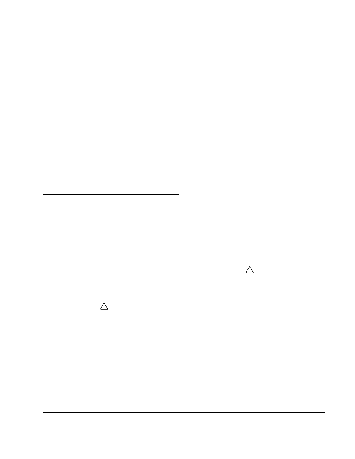
WATER LEVEL
The water level sensor is set to maintain the proper
water level above the water pump housing. The water
level is not adjustable.
If the water level is incorrect, check the water level probe
for damage (probe bent, etc.). Repair or replace the
probe as necessary.
Figure 3-2. Water Level Probe
ICE THICKNESS CHECK
The ice thickness probe is factory-set to maintain the ice
bridge thickness at 1/8" (3.2 mm).
NOTE: Make sure the water curtain is in place when
performing this check. It prevents water from splashing
out of the water trough.
1. Inspect the bridge connecting the cubes. It should
be about 1/8" (3.2 mm) thick.
2. If adjustment is necessary, turn the ice thickness
probe adjustment screw clockwise to increase
bridge thickness, counterclockwise to decrease
bridge thickness.
NOTE: Turning the adjustment 1/3 of a turn will change
the ice thickness about 1/16" (1.5 mm).
Figure 3-3. Ice Thickness Check
3. Make sure the ice thickness probe wire and the
bracket do not restrict movement of the probe.
SV1616
SV1208
ADJUSTING SCREW
1/8” ICE BRIDGE THICKNESS
Page 37
Section 3 Maintenance
Part No. 80-1100-3 3-3
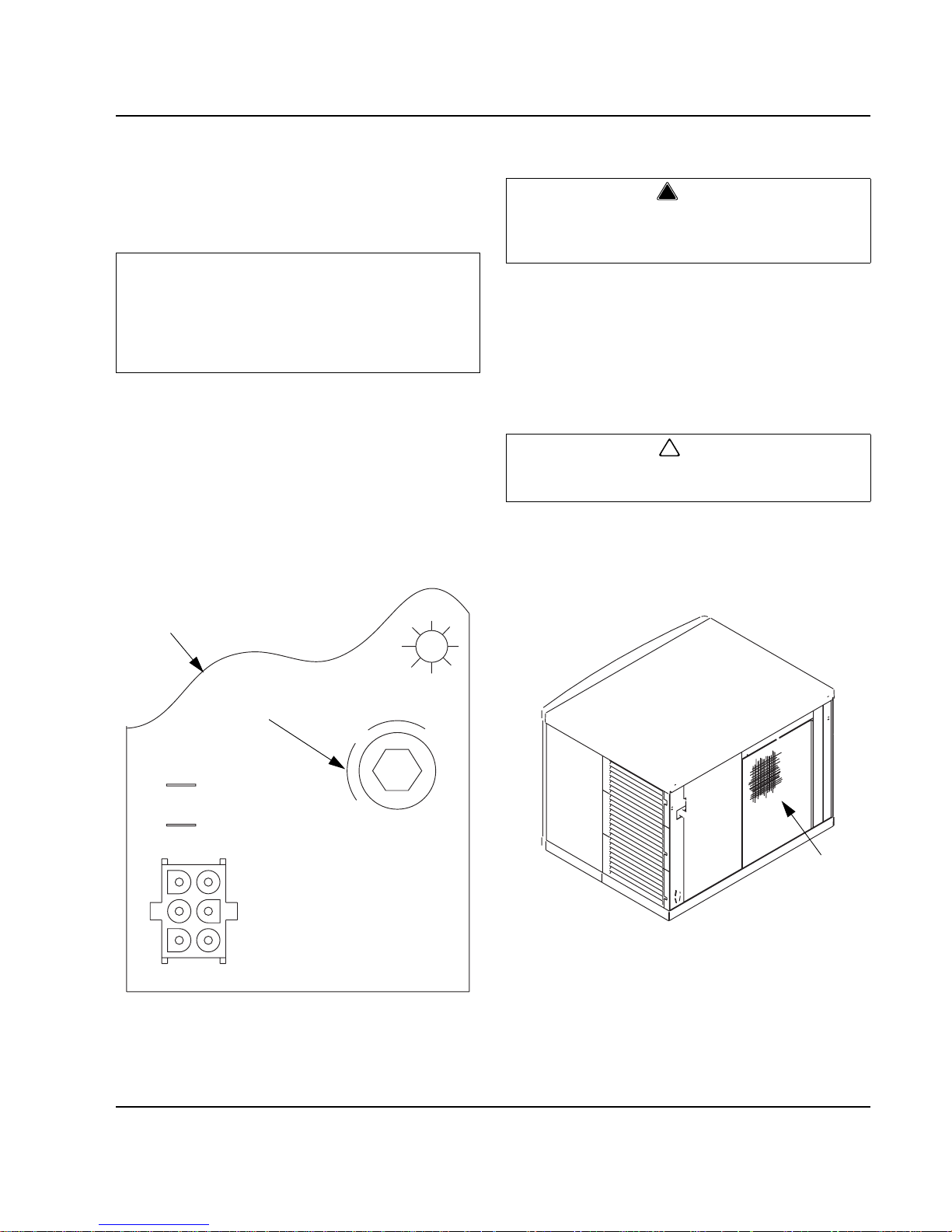
HARVEST SEQUENCE WATER PURGE
The harvest sequence water purge adjustment may be
used when the ice machine is hooked up to special
water systems, such as a de-ionized water treatment
system.
• The harvest sequence water purge may be set to 15,
30, or 45 seconds.
• During the harvest sequence water purge, the water
fill valve energizes and de-energizes by time. The
water purge must be at the factory setting of 45
seconds for the water fill valve to energize during the
last 15 seconds of the water purge. If it is set to less
than 45 seconds, the water fill valve will not energize
during the water purge.
Figure 3-4. Water Purge Adjustment
Cleaning the Condenser
AIR-COOLED CONDENSER
(SELF-CONTAINED AND REMOTE MODELS)
A dirty condenser restricts airflow, resulting in
excessively high operating temperatures. This reduces
ice production and shortens component life. Clean the
condenser at least every six months. Follow the steps
below.
1. The washable aluminum filter on self-contained ice
machines is designed to catch dust, dirt, lint and
grease. This helps keep the co ndenser clean. Clean
the filter with a mild soap and water solution.
Figure 3-5. Self-Contained Air-Cooled Filter
2. Clean the outside of the condenser (bottom of a
remote condenser) with a soft brush or a vacuum
with a brush attachment. Clean from top to bottom,
not side to side. Be careful not to bend the
condenser fins.
Continued on next page …
Important
The harvest sequence water purge is f actory-set at
45 seconds. A shorter purge setting (with standard
water supplies such as city water) is not
recommended. This can increase water system
cleaning and sanitizing requirements.
15
30
45
SV1617
CONTROL
BOARD
WATER PURGE
ADJUSTMENT
!
Warning
Disconnect electric power to the ice machine and
the remote condenser at the electric service switch
before cleaning the condenser.
!
Caution
The condenser fins are sharp. Use care when
cleaning them.
SV1608
AIR FILTER
Page 38

Maintenance Section 3
3-4 Part No. 80-1100-3
3. Shine a flashlight through the condenser to check
for dirt between the fins. If dirt remains:
A. Blow compressed air through the condenser fins
from the inside. Be careful not to bend the fan
blades.
B. Use a commercial condenser coil cleaner.
Follow the directions and cautions supplied with
the cleaner.
4. Straighten any bent condenser fins with a fin comb.
Figure 3-6. Straighten Bent Condenser Fins
5. Carefully wipe off the fan blades and motor with a
soft cloth. Do not bend the fan blades. If the fan
blades are excessively dirty, wash with warm, soapy
water and rinse thoroughly.
WATER-COOLED CONDENSER
AND WATER REGULATING VALVE
Symptoms of restrictions in the condenser water circuit
include:
• Low ice production
• High water consumption
• High operating temperatures
• High operating pressures
If the ice machine is experiencing any of these symptoms,
the water-cooled condenser and water regulating valve
may require cleaning due to scale build-up.
The cleaning procedures require special pumps and
cleaning solutions. Follow the manufacturer’s
instructions for the specific cleaner being used.
!
Caution
If you are cleaning the condenser fan blades with
water, cover the fan motor to prevent water
damage.
CONDENSER
SV1515
FIN COMB
“COMB”
DOWN
ONLY
Page 39

Section 3 Maintenance
Part No. 80-1100-3 3-5
Interior Cleaning and Sanitizing
GENERAL
Clean and sanitize the ice machine every six months for
efficient operation. If the ice machine requires more
frequent cleaning and sanitizing, consult a qualified
service company to test the water quality and
recommend appropriate water treatment or installa tion
of AuCS
accessory (Automatic Cleaning System). If
required, an extremely dirty ice machine may be taken
apart for cleaning and sanitizing.
MANITOWOC’S PATENTED CLEANING OR
SANITIZING TECHNOLOGY
Manitowoc Ice Machines include technology that allows
the initiation and completion of a cleaning or sanitizing
cycle at the flip of a switch. This cycle will permit
cleaning or sanitizing of all surfaces that come in contact
with the water distribution system. Periodic maintenance
must be performed that includes sanitizing the bin (or
dispenser) and adjacent surface areas, which cannot be
contacted by the water distribution system.
This technology will also allow initiation and completion
of a clean or sanitize cycle, after which the ice machine
automatically starts ice making again.
Refer to the cleaning or sanitizing procedure for
complete details.
The AuCS Accessory can be set to automatically start
and finish a clean or sanitize cycle every 2, 4, or 12
weeks. This accessory monitors ice-making cycles and
initiates a cleaning or sanitizing cycle automatically.
Refer to Automatic Cleaning System (AuCS) Accessory
for further details.
ALPHASAN
The goal of AlphaSan is to keep the plastic surfaces of
an ice machine cleaner, by reducing or delaying the
formation of bio-film. The active ingredient in
AlphaSan
is the element silver in the form of silver ions
(Ag+). AlphaSan
slowly releases silver ions via an ion
exchange mechanism. When AlphaSan
is
compounded directly into a plastic part, a controlled
release of silver ions from the surface is regulated to
maintain an effective concentration at or near the
surface of the plastic ice machine part. AlphaSan’s
unique ability to effectively control the release of silver
not only protects against undesired discoloration of the
plastic, but also will last the life of the plastic part.
Although AlphaSan
helps prevent bio-film build up it
does not eliminate the need for periodic cleaning and
maintenance. AlphaSan
has no adverse effect on the
taste of the ice or beverage.
!
Caution
Use only Manitowoc approved Ice Machine Cleaner
(part number 94-0546-3) and Sanitizer (p ar t number
94-0565-3). It is a violation of Federal law to use
these solutions in a manner inconsistent with th eir
labeling. Read and understand all labels printed on
bottles before use.
!
Caution
Do not mix Cleaner and Sanitizer solutions together.
It is a violation of Federal law to use these solutions
in a manner inconsistent with their labeling.
!
Warning
Wear rubber gloves and safety goggles (and/or face
shield) when handling ice machine Cleaner or
Sanitizer.
Page 40

Maintenance Section 3
3-6 Part No. 80-1100-3
CLEANING PROCEDURE
Ice machine cleaner is used to remove lime scale or
other mineral deposits. It is not used to remove algae or
slime. Refer to the section on Sanitizing for removal of
algae and slime.
Step 1 Set the toggle switch to the OFF position after
ice falls from the evaporator at the end of a Harvest
cycle. Or, set the switch to the OFF position and allow
the ice to melt off the evaporator.
Step 2 To start cleaning, plac e the toggle switch in the
CLEAN position. The water will flow through the water
dump valve and down the drain. The Clean light will turn
on to indicate the ice machine is in the Cleaning mode.
Step 3 Wait about one minute or until water starts to
flow over the evaporator.
Step 4 Add the proper amount of Manitowoc Ice
Machine Cleaner to the water trough.
Step 5 The ice machine will automatically time out a
ten minute cleaning cycle, followed by six rinse cycles,
and stop. The Clean light will turn off to indicate the
Cleaning mode is completed. This entire cycle lasts
approximately 25 minutes.
Step 6 When the cleaning process stops, move the
toggle switch to OFF position. Refer to “Sanitizing
Procedure” on the next page.
Step 7
A. The ice machine may be set to start and finish a
cleaning procedure then automatically start ice
making again.
B. You must wait about one minute into the
cleaning cycle (until water starts to flow over the
evaporator) then move the switch from CLEAN
to ICE position.
C. When the cleaning cycle is completed, an ice
making sequence will start automatically.
!
Caution
Never use anything to force ice from the evaporator.
Damage may result.
Model Amount of Cleaner
Q200 Q280 Q320 Q370 3 ounces (90 ml)
Q420 Q450 Q600 Q800 5 ounces (150 ml)
Q1000 Q1300
Q1600 Q1800
9 ounces (270 ml)
Important
After the toggle switch is moved to the ICE position,
opening the curtain switch will interrupt the cleaning
sequence. The sequence will resume from the point
of interruption when the curtain switch closes.
Page 41

Section 3 Maintenance
Part No. 80-1100-3 3-7
SANITIZING PROCEDURE
Use sanitizer to remove algae or slime. Do not use it to
remove lime scale or other mineral deposits.
Step 1 Set the toggle switch to the OFF position after
ice falls from the evaporator at the end of a Harvest
cycle. Or, set the switch to the OFF position and allow
the ice to melt off the evaporator.
Step 2 Refer to Removal of Parts For Cleaning/
Sanitizing and remove ice machine parts.
Step 3 Mix a solution of water and sanitizer.
Step 4 Use the sanitizing solution and a sponge or
cloth to sanitize (wipe) all parts and interior surfaces of
the ice machine. Sanitize the following areas:
A. Side walls
B. Base (area above water trough)
C. Evaporator plastic parts
D. Bin or dispenser
Step 5 Rinse all sanitized areas with clear water.
Step 6 Install the removed parts, restore power and
place toggle switch in the ice position.
!
Caution
Never use anything to force ice from the evaporator.
Damage may result.
!
Warning
Disconnect electric power to the ice machine (and
dispenser if applicable) at the electric switch box
before proceeding.
Solution Type Water Mixed With
Sanitizer 4 gal. (15 l) 3 oz (90 ml) sanitizer
Page 42

Maintenance Section 3
3-8 Part No. 80-1100-3
AUTOMATIC CLEANING SYSTEM (AuCS)
This accessory monitors ice making cycles and initiates
cleaning (or sanitizing) procedures automatically. The
AuCS
Accessory can be set to automatically clean or
sanitize the ice machine every 2, 4, or 12 weeks.
Automatic Operation
The following occurs when the toggle switch is in the ICE
position:
• The ice machine control board counts the number of
ice harvest cycles.
•The AuCS
accessory interrupts the ice making
mode and starts the cleaning (or sanitizing) mode
when the harvest count equals the “Frequency of
Cleaning” setting of the AuCS
.
• When the automatic cleaning (or sanitizing) cycle is
complete (approximately 25 minutes), ice making
resumes automatically, and the “Harvest Count” is
reset to zero.
Manual Start Operat ion
Step 1 Set the toggle switch to the OFF position after
ice falls from the evaporator at the end of a Harvest
cycle. Or, set the switch to the OFF position and allow
the ice to melt off the evaporator.
Step 2 To start the automatic cleaning system, move
the toggle switch to the CLEAN position. The water will
flow through the water dump valve and down the drain.
The Clean light will turn on to indicate the ice machine is
in the Self Cleaning mode. The AuCS
then
automatically adds cleaner or sanitizer to the ice
machine.
Step 3 The ice machine will automatically time out a
ten minute cleaning or sanitizing cycle, followed by six
rinse cycles, (de-energize the Clean light) and stop. This
entire cycle lasts approximately 25 minutes.
Step 4 After the cleaning or sanitizing cycle stops,
move the toggle switch to ICE position.
Step 5
A. The ice machine may be set to start and finish a
cleaning or sanitizing cycle, then automatically
start ice making again.
B. You must wait about one minute into the
cleaning cycle (until water starts to flow over the
evaporator), then move the toggle switch from
CLEAN to ICE position.
C. When the cleaning or sanitizing cycle is
completed, the clean light will turn off and an ice
making sequence will start automatically.
!
Caution
Refer to the AuCS Accessory Installation - Use
and Care Manual for complete details on the
installation, operation, maintenance and cautionary
statements of this accessory.
Important
Opening the curtain switch will interrupt the cleaning
or sanitizing sequence. The sequence will resume
from the point of interruption when the curtain recloses.
!
Caution
Never use anything to force ice from the evaporator.
Damage may result.
Page 43

Section 3 Maintenance
Part No. 80-1100-3 3-9
REMOVAL OF PARTS FOR CLEANING/SANITIZING
1. Turn off the water supply to the ice machine at the
water service valve.
2. Remove the water curtain and the components you
want to clean or sanitize. See the following pages for
removal procedures for these parts.
3. Soak the removed part(s) in a properly mixed
solution.
4. Use a soft-bristle brush or sponge (NOT a wire
brush) to carefully clean the parts.
5. Use the solution and a brush to clean the top, sides,
and bottom evaporator extrusions; the inside of the
ice machine panels; and the entire inside of the bin.
6. Thoroughly rinse all of the parts and surfaces with
clean water.
7. Install the removed parts.
NOTE: Incomplete rinsing of the ice thickness probe or
water level probe may leave a residue. This could cause
the ice machine to malfunction. For best results, brush o r
wipe the probes off while rinsing it. Thoroughly dry the
probes before installing them.
8. Turn on the water and electrical supply.
!
Warning
Disconnect electric power to the ice machine at the
electric switch box before proceeding.
!
Warning
Wear rubber gloves and safety goggles (and/or face
shield) when handling Ice Machine Cleaner or
Sanitizer.
Solution Type Water Mixed With
Cleaner 1 gal. (4 l) 16 oz (500 ml) cleaner
Sanitizer 4 gal. (15 l) 1 oz (30 ml) sanitizer
!
Caution
Do not mix Cleaner and Sanitizer solutions together.
It is a violation of Federal law to use these solutions
in a manner inconsistent with their labeling.
!
Caution
Do not immerse the water pump motor in the
cleaning or sanitizing solution.
Page 44

Maintenance Section 3
3-10 Part No. 80-1100-3
Water Dump Valve
The water dump valve normally does not require
removal for cleaning. To determine if removal is
necessary:
1. Locate the water dump valve.
2. Set the toggle switch to ICE.
3. While the ice machine is in the freeze mode, check
the dump valve’s clear plastic outlet drain hose for
leakage.
A. If the dump valve is leaking, remove,
disassemble and clean it.
B. If the dump valve is not leaking, do not remove
it. Instead, follow the “Cleaning Procedure” on
Page 3-5.
Follow the procedure below to remove the dump valve.
1. If so equipped, remove the water dump valve shield
from its mounting bracket.
2. Lift and slide the coil retainer cap fro m the top of the
coil.
3. Note the position of the coil assembly on the valve
for assembly later. Leaving the wires attached, lift
the coil assembly off the valve body and the
enclosing tube.
4. Press down on the plastic nut on the enclosing tube
and rotate it 1/4 turn. Remove the enclosing tube,
plunger, and plastic gasket from the valve body.
NOTE: At this point, the water dump valve can easily be
cleaned. If complete removal is desired, continue with
step 5.
Figure 3-7. Dump Valve Removal
NOTE: During cleaning, do not stretch, damage or
remove the spring from the plunger . If it is removed, slide
the spring’s flared end into the plunger’s slotted top
opening until the spring contact s th e plun ger spri ng stop.
5. Remove the valve body.
6. Remove the tubing from the dump valve by twisting
the clamps off.
7. Remove the two screws securing the dump valve
and the mounting bracket.
Figure 3-8. Dump Valve Disassembly
!
Warning
Disconnect the electric power to the ice machine at
the electric service switch box and turn off the water
supply before proceeding.
Important
The plunger and the inside of the enclosing tube
must be completely dry before assembly.
CAP
PLUNGER
SPRING STOP
SPRING
PLUNGER
DIAPHRAM
VALVE BODY
ENCLOSING
TUBE
COIL
Page 45
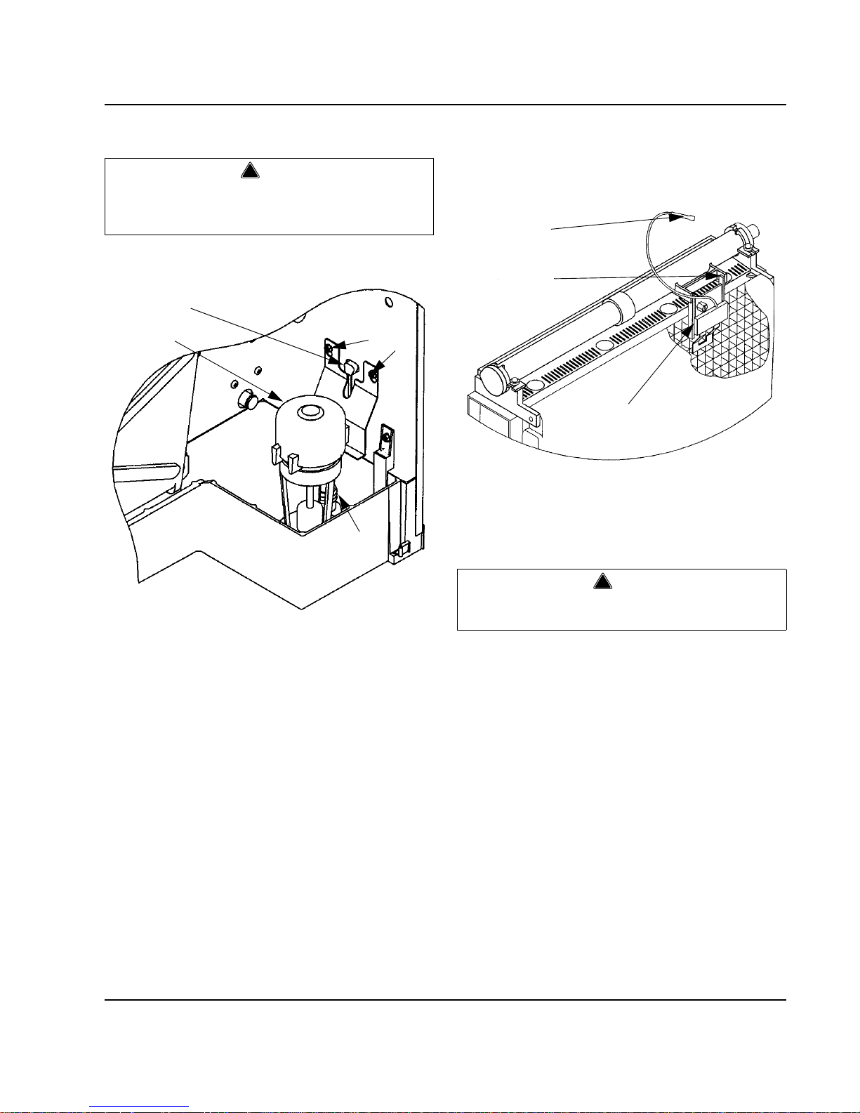
Section 3 Maintenance
Part No. 80-1100-3 3-11
Water Pump
1. Disconnect the water pump power cord.
Figure 3-9. Water Pump Removal
2. Disconnect the hose from the pump outlet.
3. Loosen the screws securing the pump mounting
bracket to the bulkhead.
4. Lift the pump and bracket assembly off the screws.
Ice Thickness Probe
1. Compress the side of the ice thickness probe near
the top hinge pin and remove it from the bracket.
Figure 3-10. Ice Thickness Probe Removal
NOTE: At this point, the ice thickness probe can easily
be cleaned. If complete removal is desired, continue with
step 2 below.
2. Disconnect the wire lead from the control board
inside the electrical control box.
Ice Thickness Probe Cleaning
1. Mix a solution of Manitowoc ice machine cleaner
and water (2 ounces of cleaner to 16 ounces of
water) in a container.
2. Soak ice thickness probe in container of cleaner/
water solution while disassembling and cleaning
water circuit components (soak ice thickness probe
for 10 minutes or longer).
3. Clean all ice thickness probe surfaces including all
plastic parts (do not use abrasives). Verify the ice
thickness probe cavity is clean. Thoroughly rinse ice
thickness probe (including cavity) with clean water,
then dry completely. Incomplete rinsing and
drying of the ice thickness probe can cause
premature harvest.
4. Reinstall ice thickness probe, then sanitize all ice
machine and bin/dispenser interior surfaces.
!
Warning
Disconnect the electric power to the ice machine at
the electric service switch box and turn off the water
supply.
SV1618
POWER
CORD
WATER
PUMP
LOOSEN
SCREWS
PUMP
OUTLET
!
Warning
Disconnect the electric power to the ice machine at
the electric service switch box.
SV1619
DISCONNECT
WIRE LEAD
COMPRESS
HINGE PIN TO
REMOVE
ICE
THICKNESS
PROBE
Page 46
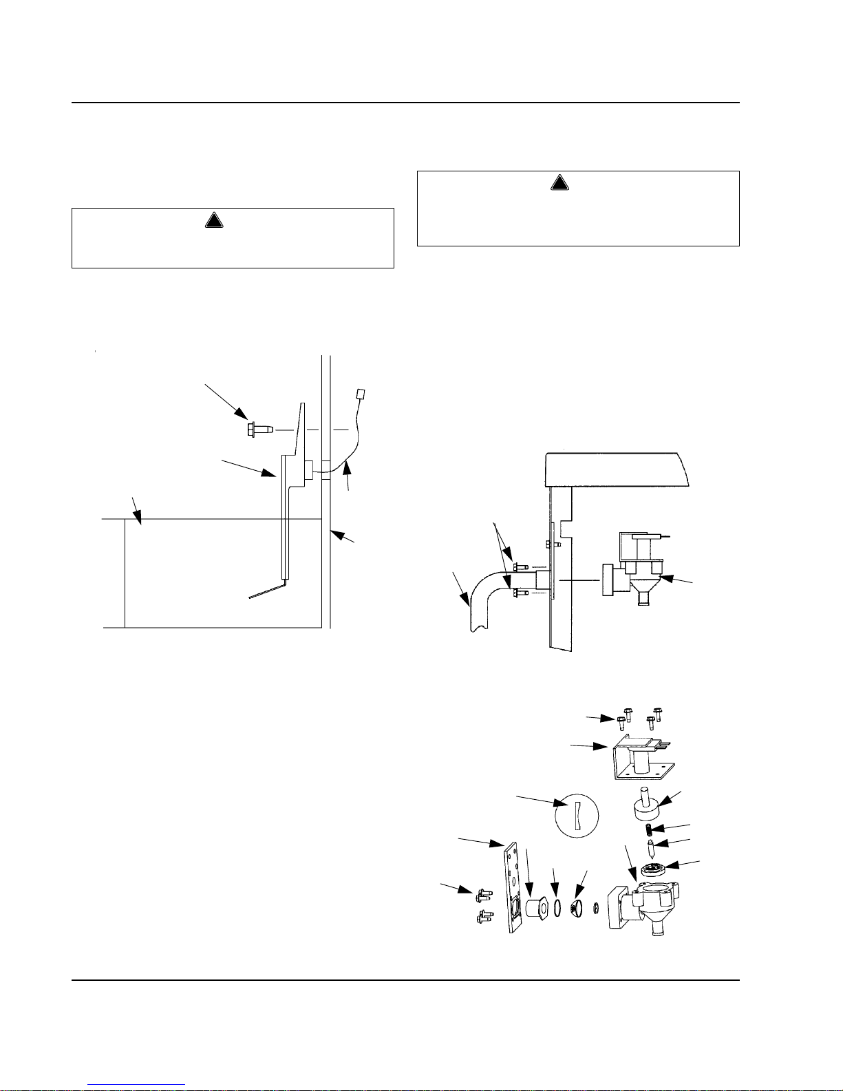
Maintenance Section 3
3-12 Part No. 80-1100-3
Water Level Probe
1. Loosen the screw that holds the water level probe in
place. The probe can easily be cleaned at this point
without proceeding to step 2.
2. If complete removal is required, disconnect the wire
lead from the control board inside the electrical
control box.
Figure 3-11. Water Level Probe Removal
Water Inlet Valve
The water inlet valve normally does not require removal
for cleaning. Follow the instructions below to determine if
removal is necessary.
1. Set the ICE/OFF/CLEAN switch to OFF. Locate the
water inlet valve (in the compressor area of the ice
machine). It pours water into the water trough.
2. When the ice machine is off, the water inlet valve
must completely stop water flow into the machine.
Watch for water flow. If water flows, remove,
disassemble and clean the valve.
3. When the ice machine is on, the water inlet valve
must allow the proper water flow through it. Set the
toggle switch to ON. Watch for water flow into the ice
machine. If the water flow is slow or only trickles into
the ice machine, remove, disassemble, and clean
the valve.
Follow the procedure below to remove the water inlet
valve.
1. Remove the valve shield if necessary.
2. Remove the filter access screws that hold the valve
in place.
NOTE: The water inlet valve can be disassembled and
cleaned without disconnecting the incoming water
supply line to the ice machine.
3. Remove, clean, and install the filter screen.
4. If necessary, remove the enclosure tube access
screws to clean interior components.
Figure 3-12. Water Inlet Valve Removal
Figure 3-13. Exploded View of Water Inlet Valve
!
Warning
Disconnect the electrical power to the ice machine
at the electrical disconnect before proceeding.
SCREW
WATER
LEVEL
PROBE
SV1621
WATER
TROUGH
WIRE
LEAD
ICE
MACHINE
SIDE
PANEL
!
Warning
Disconnect the electric power to the ice machine at
the electric service switch box and turn off the water
supply before proceeding.
SV1622
FILTER
ACCESS
SCREWS
INCOMING
WATER
LINE
WATER
INLET
VALVE
SV1623
ENCLOSURE TUBE
ACCESS SCREWS
ELECTRICAL
SOLENOID
RESTRICTOR
(FLAT SIDE MUST
FACE OUT)
MOUNTING
PLATE
FILTER
ACCESS
SCREWS
FITTING
O-RING
ENCLOSURE
TUBE
SPRING
PIN
RUBBER
SEAL
VALVE
BODY
FILTER
SCREEN
Page 47
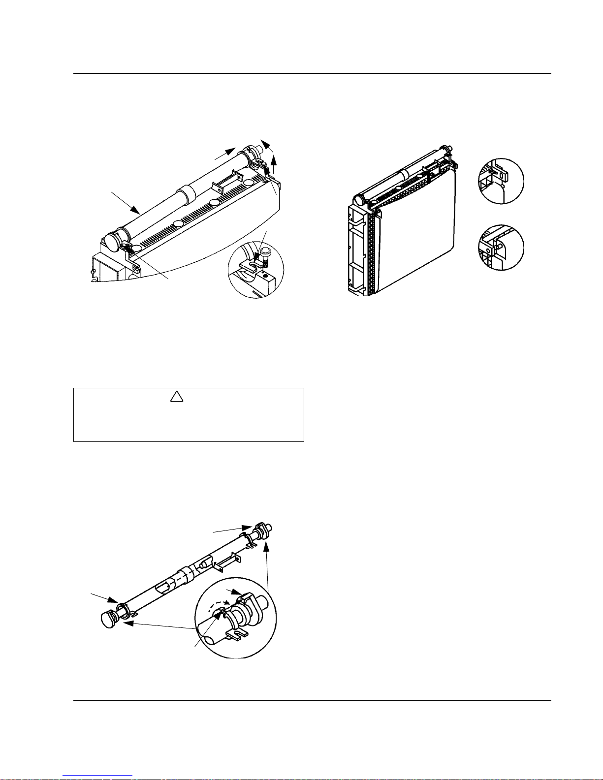
Section 3 Maintenance
Part No. 80-1100-3 3-13
Water Distribution Tube
1. Disconnect the water hose from the distribution
tube.
Figure 3-14. Water Distribution Tube Removal
1. Loosen the two thumbscrews which secure the
distribution tube.
2. Lift the right side of the distribution tube up off the
locating pin, then slide it back and to the right.
3. Disassemble for cleaning.
A. Twist both of the inner tube ends until the tabs
line up with the keyways.
B. Pull the inner tube ends outward.
Figure 3-15. Water Distribution Tube Disassembly
Water Curtain
1. Gently flex the curtain in the center and remove it
from the right side.
Figure 3-16. Water Curtain Removal
2. Slide the left pin out.
!
Caution
Do not force this removal. Be sure the locating pin is
clear of the hole before sliding the distribution tube
out.
SV1620
1. LIFT UP
2. SLIDE BACK
3. SLIDE TO RIGHT
DISTRIBUTION
TUBE
THUMBSCREW
THUMBSCREW
LOCATING
PIN
3
2
1
SV1211
INNER TUBE
TAB
KEYWAY
INNER TUBE
SV1213
STEP 1
STEP 2
Page 48

Maintenance Section 3
3-14 Part No. 80-1100-3
Water Treatment/Filtration
GENERAL
Local water conditions may require the installation of a
water treatment system to inhibit scale formation, filter
out sediment, and remove chlorine taste and odor.
Consult your local distributor for information on
Manitowoc’s full line of NSF
-certified Tri-Liminator
filtration systems.
FILTER REPLACEMENT PROCEDURE
Tri-Liminator
systems include a pre-filter and a primary
filter. For maximum filtration efficiency, replace the
primary filter cartridge every six months. If the filter
gauge reading drops below 20 psig prior to six months
usage, replace the pre-filter first.
1. Turn off the water supply at the inlet shutoff valve.
Figure 3-17. Typical Tri-Liminator
Water Filtration System
2. Depress the pressure release button to relieve the
pressure.
3. Unscrew the housing from the cap.
4. Remove the used filter cartridge from the housing
and discard it.
5. Remove the O-ring from the housing groove. Wipe
the housing groove and the O-ring clean.
6. Lubricate the O-ring with petroleum jelly.
7. Press the O-ring into the housing groove.
8. Insert a new filter cartridge into the housing. Make
sure it slips down over the housing standpipe.
9. Screw the housing on to the cap and carefully handtighten it.
10. Repeat steps 3-9 for each filter housing.
11. Turn on the water supply to allow the housing and
filter to slowly fill with water.
12. Depress the pressure release button to release
trapped air from the housing.
13. Check for leaks.
CAP
CARTRIDGE
SEAL
PRESSURE
RELEASE BUTTON
PRE-FILTER
PRIMARY
FILTER
OUTLET SIDE
O-RING
SHUT OFF
VALVE
SEAL
HOUSING
INLET SIDE
!
Caution
Hand-tighten only. Do not overtighten. Do not use a
spanner wrench.
Page 49
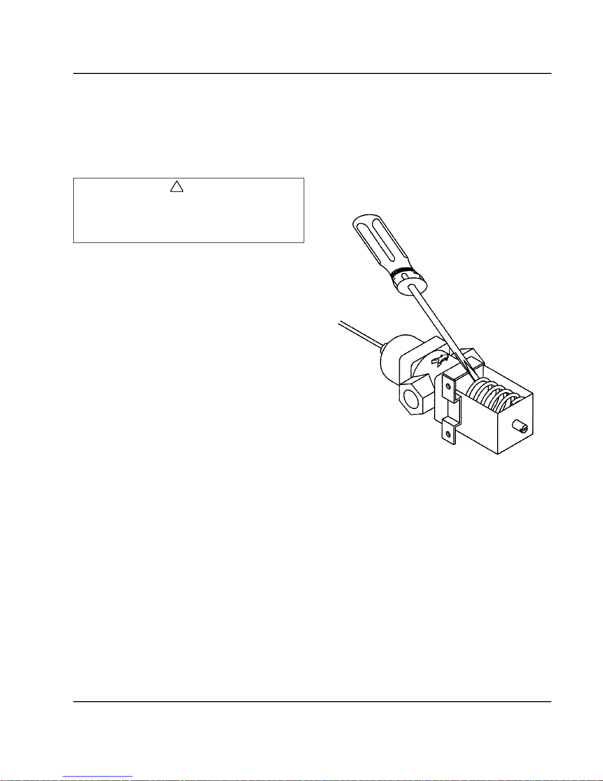
Section 3 Maintenance
Part No. 80-1100-3 3-15
Removal from Service/Winterization
GENERAL
Special precautions must be taken if the ice machine is
to be removed from service for an extended period of
time or exposed to ambient temperatures of 32°F (0°C)
or below.
Follow the applicable procedure below.
SELF-CONTAINED AIR-COOLED ICE MACHINES
1. Disconnect the electric power at the circuit breaker
or the electric service switch.
2. Turn off the water supply.
3. Remove the water from the water trough.
4. Disconnect and drain the incoming ice-making water
line at the rear of the ice machine.
5. Blow compressed air in both the incoming water and
the drain openings in the rear of the ice machine
until no more water comes out of the inlet water lines
or the drain.
6. Make sure water is not trapped in any of the water
lines, drain lines, distribution tubes, etc.
WATER-COOLED ICE MACHINES
1. Perform steps 1-6 under “Self-Contained Air-Cooled
Ice Machines.”
2. Disconnect the incoming water and drain lines from
the water-cooled condenser.
3. Insert a large screwdriver between the bottom spring
coils of the water regulating valve. Pry upward to
open the valve.
Figure 3-18. Pry Open the Water Regulating Valve
4. Hold the valve open and blow compressed air
through the condenser until no water remains.
REMOTE ICE MACHINES
1. Move the ICE/OFF/CLEAN switch to OFF.
2. “Frontseat” (shut off) the receiver service valves.
Hang a tag on the switch as a reminder to open the
valves before restarting.
3. Perform steps 1-6 under “Self-Contained Air-Cooled
Ice Machines.”
AUCS
Accessory
Refer to the AuCS
Accessory manual for winterization
of the AuCS
Accessory.
!
Caution
If water is allowed to remain in the ice machine in
freezing temperatures, severe damage to some
components could result. Damage of this nature is
not covered by the warranty.
SV1624
Page 50

Maintenance Section 3
3-16 Part No. 80-1100-3
THIS PAGE INTENTIONALLY LEFT BLANK
Page 51

Part No. 80-1100-3 4-1
Section 4
Ice Machine Sequence of Operation
Self-Contained Air- and Water-Cooled
Q200/Q280/Q320/Q370/Q420/Q450/Q600/Q800/Q1000/Q1300/Q1600/Q1800
INITIAL START-UP OR START-UP AFTER
AUTOMATIC SHUT-OFF
1. Water Purge
Before the compressor starts, the water pump and water
dump solenoid are energized for 45 seconds, to
completely purge the ice machine of old water. This
feature ensures that the ice making cycle starts with
fresh water.
The harvest valve(s) is also energized during water
purge, although it stays on for an additional 5 seconds
(50 seconds total on time) during the initial refrigeration
system start-up.
2. Refrigeration System Start-Up
The compressor starts after the 45 second water purge,
and it remains on throughout the entire Freeze and
Harvest Sequences. The water fill valve is energized at
the same time as the compressor. It remains on until the
water level sensor closes for 3 continuous seconds, or
until a six-minute time period has expired. (See “Water
Inlet Valve Safety Shutoff,” Page 6-50.) The harvest
valve(s) remains on for 5 seconds during initial
compressor start-up and then shuts of f.
At the same time the compressor starts, the condenser
fan motor (air-cooled models) is supplied with power
throughout the entire Freeze and Harvest Sequences.
The fan motor is wired through a fan cycle pressure
control, therefore it may cycle on and off. (The
compressor and condenser fan motor are wired through
the contactor. As a result, anytime the contactor coil is
energized, the compressor and fan motor are supplied
with power.)
FREEZE SEQUENCE
3. Prechill
The compressor is on for 30 seconds prior to water flow,
to prechill the evaporator.
4. Freeze
The water pump restarts after the 30 second prechill. An
even flow of water is directed across the evaporator and
into each cube cell, where it freezes. The water fill valve
will cycle on and then off one more time to refill the water
trough.
When sufficient ice has formed, the water flow (not the
ice) contacts the ice thickness probe. After
approximately 7 seconds of continual water contact, the
harvest sequence is initiated. The ice machine cannot
initiate a harvest sequence until a 6 minute freeze lock
has been surpassed.
Figure 4-1. Freeze Sequence
(Typical Q450 Shown)
Continued on next page …
Page 52

Ice Machine Sequence of Operation Section 4
4-2 Part No. 80-1100-3
HARVEST SEQUENCE
5. Water Purge
The water pump continues to run, and the water dump
valve energizes for 45 seconds to purge the water in the
sump trough. The water fill valve energizes (turns on)
and de-energizes (turns off) strictly by time. The water fill
valve energizes for the last 15 seconds of the 45-second
water purge. The water purge must be at the factory
setting of 45 seconds for the fill valve to energize during
the last 15 seconds of the Water Purge. If set at less
than 45 seconds the water fill valve does not energize
during the water purge.
After the 45 second water purge, the water fill valve,
water pump and dump valve de-energize. (Refer to
“Water Purge Adjustment” on Page 3-3 for details.) The
harvest valve also opens at the beginning of the water
purge to divert hot refrigerant gas into the evaporator.
6. Harvest
The harvest valve(s) remains open and the refrigerant
gas warms the evaporator causing the cubes to slide, as
a sheet, off the evaporator and into the storage bin. The
sliding sheet of cubes swings the water curtain out,
opening the bin switch. The momentary opening and reclosing of the bin switch terminates the harvest
sequence and returns the ice machine to the freeze
sequence (Step 3 - 4.)
Figure 4-2. Harvest Sequence (Typical Q450 Shown)
AUTOMATIC SHUT-OFF
7. Automatic Shut-Off
When the storage bin is full at the end of a harvest
sequence, the sheet of cubes fails to clear the water
curtain and will hold it open. After the water curtain is
held open for 7 seconds, the ice machine shuts off. The
ice machine remains off for 3 minutes before it can
automatically restart.
The ice machine remains off until enough ice has been
removed from the storage bin to allow the ice to fall clear
of the water curtain. As the water curtain swings back to
the operating position, the bin switch re-closes and the
ice machine restarts (steps 1 - 2) , pr ovide d the 3 minute
delay period is complete.
Figure 4-3. Automatic Shut-Off (Typical Q450
Shown)
Page 53

Section 4 Ice Machine Sequence of Operation
Part No. 80-1100-3 4-3
Remote
Q450/Q600/Q800/Q1000/Q1300/Q1600/Q1800
INITIAL START-UP OR START-UP AFTER
AUTOMATIC SHUT-OFF
1. Water Purge
Before the compressor starts, the water pump and water
dump solenoid are energized for 45 seconds, to
completely purge the ice machine of old water. This
feature ensures that the ice making cycle starts with
fresh water.
The harvest valve and harvest pressure regulating
(HPR) solenoid valves also energize during water purge,
although they stay on for an additional 5 seconds (50
seconds total on time) during the initial refrigeration
system start-up.
2. Refrigeration System Start-Up
The compressor and liquid line solenoid valve energize
after the 45 second water purge and remain on
throughout the entire Freeze and Harvest Sequences.
The water fill valve is energized at the same time as the
compressor. It remains on until the water level sensor
closes for 3 continuous seconds, or until a six-minute
time period has expired. (See “Water Inlet Valve Safety
Shutoff,” Page 6-50.). The harvest valve and HPR
solenoid valves remain on for 5 seconds during initial
compressor start-up and then shut off.
The remote condenser fan motor starts at the same time
the compressor starts and remains on throughout the
entire Freeze and Harvest Sequences. (The compressor
and condenser fan motor are wired through the
contactor, therefore, anytime the contactor coil is
energized, the compressor and fan motor are on.)
FREEZE SEQUENCE
3. Prechill
The compressor is on for 30 seconds prior to water flow,
to prechill the evaporator.
4. Freeze
The water pump restarts after the 30 second prechill. An
even flow of water is directed across the evaporator and
into each cube cell, where it freezes. The water fill valve
will cycle on and then off one more time to refill the water
trough. (See Page 4-1.)
When sufficient ice has formed, the water flow (not the
ice) contacts the ice thickness probe. After
approximately 7 seconds of continual water contact, the
harvest sequence is initiated. The ice machine cannot
initiate a harvest sequence until a 6 minute freeze lock
has been surpassed.
Figure 4-4. Freeze Sequence (Typical Q450 Shown)
Continued on next page …
Page 54

Ice Machine Sequence of Operation Section 4
4-4 Part No. 80-1100-3
HARVEST SEQUENCE
5. Water Purge
The water pump continues to run, and the water dump
valve energizes for 45 seconds to purge the water in the
sump trough. The water fill valve energizes (turns on)
and de-energizes (turns off) strictly by time. The water fill
valve energizes for the last 15 seconds of the 45-second
water purge. The water purge must be at the factory
setting of 45 seconds for the fill valve to energize during
the last 15 seconds of the Water Purge. If set at less
than 45 seconds the water fill valve does not energize
during the water purge.
After the 45 second water purge, the water fill valve,
water pump and dump valve de-energize. (Refer to
“Water Purge Adjustment” on Page 3-3 for details.) The
harvest valve(s) and HPR solenoid valve also open at
the beginning of the water purge.
6. Harvest
The HPR valve and the harvest valve(s) remain open
and the refrigerant gas warms the evaporator causing
the cubes to slide, as a sheet, off the evaporator and into
the storage bin. The sliding sheet of cubes swings the
water curtain out, opening the bin switch. The
momentary opening and re-closing of the bin switch
terminates the harvest sequence and returns the ice
machine to the freeze sequence (Step 3 - 4.)
Figure 4-5. Harvest Sequence (Typical Q450 Shown)
AUTOMATIC SHUT-OFF
7. Automatic Shut-Off
When the storage bin is full at the end of a harvest
sequence, the sheet of cubes fails to clear the water
curtain and will hold it open. After the water curtain is
held open for 7 seconds, the ice machine shuts off. The
ice machine remains off for 3 minutes before it can
automatically restart.
The ice machine remains off until enough ice has been
removed from the storage bin to allow the ice to drop
clear of the water curtain. As the water curtai n swings
back to the operating position, the bin switch re-closes
and the ice machine restarts (step s 1 - 2) p rovided th e 3
minute delay period is complete.
Figure 4-6. Automatic Shut-Off (Typical Q450
Shown)
Page 55

Part No. 80-1100-3 5-1
Section 5
Water System Ice Making Sequence of Operation
NOTE: The sequence of operation is the same for selfcontained and remote models.
INITIAL START-UP OR START-UP AFTER
AUTOMATIC SHUT-OFF
1. Before the ice machine starts, the water pump and
water dump solenoid are energized for 45 seconds
to purge old water from the water trough. This
ensures that the ice-making cycle starts with fresh
water. The water fill valve energizes after the 45second water purge, and remains on until the water
level probe is satisfied.
FREEZE CYCLE
2. To pre-chill the evaporator, there is no water flow
over the evaporator for the first 30 seconds of the
freeze cycle.
3. The water pump starts after the 30-second pre-chill.
An even flow of water is directed across the
evaporator and into each cube cell.
During the first 45 seconds of the Freeze Cycle, the
water fill valve cycles on and off as many times as
needed to refill the water trough.
After the 45 seconds, the water fill valve cycles on
and off one more time to refill the water trough. The
water fill valve then remains off for the duration of
the Freeze Cycle.
WATER INLET VALVE SAFETY SHUT-OFF
This feature limits the water inlet valve to a six-minute on
time. Regardless of the water level probe input, the
control board automatically shuts off th e water inlet valve
if it remains on for 6 continuous minutes.
Figure 5-1. Water Flow Over the Evaporator
SV1677
TO DRAIN
WATER DUMP VALVE
TO DISTRIBUTION TUBE
WATER PUMP
WATER INLET VALVE
Page 56

Water System Ice Making Sequence of Operation Section 5
5-2 Part No. 80-1100-3
HARVEST CYCLE
4. The water pump and water dump solenoid are
energized for 45 seconds to purge the water from
the water trough. The water fill valve energizes for
the last 15 seconds of the 45-second purge cycle, to
flush sediment from the bottom of the water trough.
5. After the 45-second purge, the water pump and
water dump valve de-energize.
AUTOMATIC SHUT-OFF
There is no water flow during an automatic shut-off.
Figure 5-2. Water Flow Down the Drain
SV1677
TO DRAIN
WATER DUMP VALVE
TO DISTRIBUTION TUBE
WATER PUMP
WATER INLET VALVE
Page 57
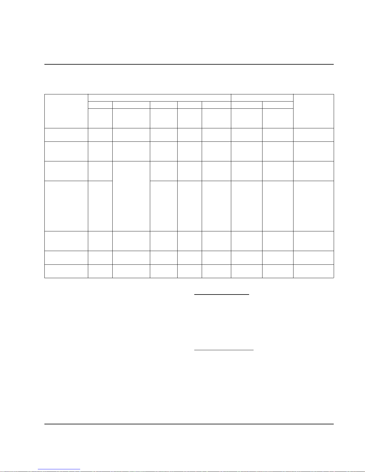
Part No. 80-1100-3 6-1
Section 6
Electrical System
Energized Parts Charts
SELF-CONTAINED AIR- AND WATER-COOLED MODELS
1. Initial Start-Up or Start-Up After Automatic Shut-Off
Condenser Fan Motor
The fan motor is wired through a fan cycle pressure
control, therefore, it may cycle on and off.
Harvest Water Purge
The circuit board has an adjustable water purge in the
harvest cycle. This permits a 15, 30 or 45 second purge
cycle.
Auto Shut-Off
The ice machine remains off for 3 minutes before it can
automatically restart. The ice machine restarts (steps 1-
2) immediately after the delay period, if the bin switch recloses prior to 3 minutes.
Safety Timers
The control board has the following non-adjustable
safety timers:
FREEZE SEQUENCE
• The ice machine is locked into the freeze cycle for
the first 6 minutes, not allowing the ice thickness
probe to initiate a harvest sequence.
• The maximum freeze time is 60 minutes, at which
time the control board automatically initiates a
harvest sequence (steps 5-6).
HARVEST SEQUENCE
The maximum harvest time is 3-1/2 minutes, at which
time the control board automatically terminates the
harvest sequence. If the bin switch is open, the ice
machine will go to automatic shut-off (step 7). If the bin
switch is closed, the ice machine will go to the freeze
sequence (steps 3-4).
Ice Making
Sequence Of
Operation
Control Board Relays Contactor
Length
Of Time
1 2 3 4 5 5A 5B
Water
Pump
Water Fill
Valve
Harvest
Valve(s)
Water
Dump
Valve
Contactor
Coil
Com-
pressor
Condenser
Fan Motor
START-UP 1
1. Water Purge
On Off On On Off Off Off 45 Seconds
2. Refrigeration
System
Start-Up
Off On On Off On On
May Cycle
On/Off
5 Seconds
FREEZE
SEQUENCE
3. Pre-Chill
Off
May cycle On/
Off during first
45 sec.
-----------
Cycles On,
then Off 1
more time
Locked Out
After Six
Minutes
Off Off On On
May Cycle
On/Off
30 Seconds
4. Freeze On Off Off On On
May Cycle
On/Off
Until 7 sec.
water contact
with ice
thickness probe
HARVEST
SEQUENCE
5. Water Purge
On
30 sec. Off,
15 sec. On
On On On On
May Cycle
On/Off
Factory-set at
45 Seconds
6. Harvest Off Off On Off On On
May Cycle
On/Off
Bin switch
activation
7. AUTOMATIC
SHUT-OFF
Off Off Off Off Off Off Off
Until bin switch
re-closes
Page 58
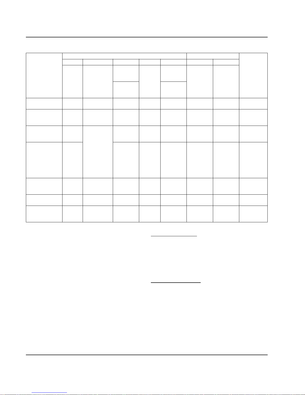
Electrical System Section 6
6-2 Part No. 80-1100-3
REMOTE MODELS
1. Initial Start-Up or Start-Up After Automatic Shut-Off
Auto Shut-Off
The ice machine remains off for 3 minutes before it can
automatically restart. The ice machine restarts (steps 1-
2) immediately after the delay period, if the bin switch recloses prior to 3 minutes.
Harvest Water Purge
The circuit board has an adjustable water purge in the
harvest cycle. This permits a 15, 30 or 45 second purge
cycle.
Safety Timers
The control board has the following non-adjustable
safety timers:
FREEZE SEQUENCE
• The ice machine is locked into the freeze cycle for
the first 6 minutes, not allowing the ice thickness
probe to initiate a harvest sequence.
• The maximum freeze time is 60 minutes, at which
time the control board automatically initiates a
harvest sequence (steps 5-6).
HARVEST SEQUENCE
• The maximum harvest time is 3-1/2 minutes, at which
time the control board automatically terminates the
harvest sequence. If the bin switch is open, the ice
machine will go to automatic shut-off (step 7). If the
bin switch is closed, the ice machine will go to the
freeze sequence (steps 3-4).
Ice Making
Sequence Of
Operation
Control Board Relays Contactor
Length
Of Time
1 2 3 4 5 5A 5B
Water
Pump
Water Fill
Valve
a. Harvest
Valve(s)
Water
Dump
Valve
a.
Contactor
Coil
Com-
pressor
Condenser
Fan Motor
b. HPR
Solenoid
b. Liquid
Line
Solenoid
START-UP
1
1. Water Purge
On Off On On
Off Off Off 45 Seconds
2. Refrigeration
System
Start-Up
Off On On Off On On On 5 Seconds
FREEZE
SEQUENCE
3. Pre-Chill
Off
May cycle
On/Off during
first 45 sec.
------------
Cycles On,
then Off 1
more time
Locked Out
After Six
Minutes
Off Off On On On 30 Seconds
4. Freeze On Off Off On On On
Until 7 sec.
water
contact with
ice thickness
probe
HARVEST
SEQUENCE
5. Water Purge
On
30 sec. Off,
15 sec. On
On On On On On
Factory-set
at 45
Seconds
6. Harvest Off Off On Off On On On
Bin switch
activation
7. AUTOMATIC
SHUT-OFF
Off Off Off Off Off Off Off
Until bin
switch re-
closes
Page 59

Section 6 Electrical System
Part No. 80-1100-3 6-3
Wiring Diagram Sequence of
Operation
SELF-CONTAINED MODELS
Initial Start-Up or Start-Up After
Automatic Shut-Off
1. WATER PURGE
Before the compressor starts, the
water pump and water dump
solenoid are energized for 45
seconds to purge old water from the
ice machine. This ensures that the
ice-making cycle starts with fresh
water.
The harvest valve(s) is also
energized during the water purge. In
the case of an initial refrigeration
start-up, it stays on for an additional
5 seconds (50 seconds total).
Figure 6-1. Self-Contained — Water Purge
Table 6-1. Self-Contained Models
1. Water Purge (45 Seconds)
Toggle Switch ICE
Bin Switch Closed
Control Board Relays
#1 Water Pump Closed / ON
#2 Water Fill Valve Open / OFF
#3 Harvest Solenoid Closed / ON
#4 Water Dump Valve Closed / ON
#5 Contactor Coil Open / OFF
Compressor OFF
Condenser Fan Motor OFF
Safety Controls (Which could stop ice machine operation)
High Pressure Cut-Out Closed
Main Fuse (On Control Board) Closed
*OVERLOAD
FAN CYCLE CONTROL
BIN SWITCH
TB35
TB33
(52)
(51)
(48)
CONTACTOR
CONTACTS
L1
(42)
(66)
(64)
ICE THICKNESS PROBE
WATER LEVEL PROBE
NOT USED
T
B35
HIGH PRES
CUTOUT
TB32
L1
(55)
RUN CAPACITOR
RUN CAPACITOR**
C
S
R
TB34
(53)
(47)
(85) (86)
COMPRESSOR
FAN MOTOR
(AIR COOLED ONLY)
R
R
(45)
(46) (50)
PTCR
BIN SWITCH LIGHT
HARVEST LIGHT/
SAFETY LIMIT CODE LIGHT
CLEAN LIGHT
WATER LEVEL
(49)
(63)
(62)
(66)
(65)
(69)
ICE
OFF
CLEAN
(67)
(68)
1F
1C
LOW D.C.
VOLTAGE
PLUG
(62)
1G
TOGGLE SWITCH
68
67
69
66
62
VIEW FOR WIRING
INTERNAL WORKING
VIEW
TB37
(74)
(59)
(73)
(56)
CONTACTOR
COIL
TERMINATES AT
PIN CONNECTION
TB3
0
TB3
0
TB30
TB30
L2 (N)
SEE SERIAL PLATE FOR VOLTAGE
(58)
FUSE (7A)
TRANS.
2
4
1
3
5
(61)
(60)
TB31
(76)
(98)
(57)
(99)
(75)
HARVEST
SOLENOID
DUMP
SOLENOID
(81)
WATER
PUMP
(77)
(80)
(21)
(22)
WATER
VALVE
TB30
TB30
(20)
SV1646-1
Page 60
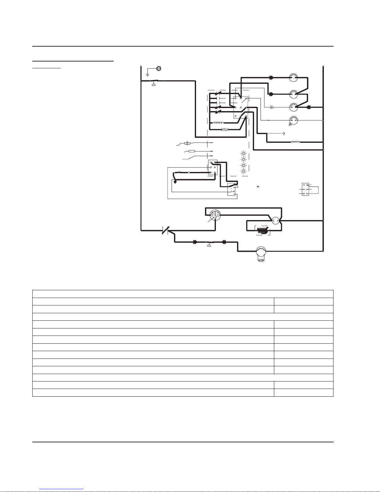
Electrical System Section 6
6-4 Part No. 80-1100-3
2. REFRIGERATION SYSTEM
START-UP
The compressor starts after the 45second water purge, and it remains
on throughout the Freeze and
Harvest cycles.
The water fill valve is energized at
the same time as the compressor. It
remains on until the water level
sensor closes for 3 continuous
seconds.
The harvest valve(s) remains on for
the first 5 seconds of the initial
compressor start-up.
At the same time the compressor
starts, the condenser fan motor (aircooled models) is supplied with
power. It continues to be supplied
with power throughout the Freeze
and Harvest cycles.
The fan motor is wired through a fan
cycle pressure control, and may
cycle on and off. (The compressor
and the condenser fan motor are
wired through the contactor . Any time
the contactor coil is energized, these
components are supplied with
power.)
Figure 6-2. Self-Contained — Refrigeration System Start-Up
Table 6-2. Self-Contained Models
2. Refrigeration System Start Up (5 Seconds)
Toggle Switch ICE
Bin Switch Closed
Control Board Relays
#1 Water Pump Open / OFF
#2 Water Fill Valve Closed / ON
#3 Harvest Solenoid Closed / ON
#4 Water Dump Valve Open / OFF
#5 Contactor Coil Closed / ON
Compressor ON
Condenser Fan Motor ON
Safety Controls (Which could stop ice machine operation)
High Pressure Cut-Out Closed
Main Fuse (On Control Board) Closed
*OVERLOAD
FAN CYCLE CONTROL
BIN SWITCH
TB35
TB33
(52)
(51)
(48)
CONTACTOR
CONTACTS
L1
(42)
(66)
(64)
ICE THICKNESS PROBE
WATER LEVEL PROBE
NOT USED
T
B35
HIGH PRES
CUTOUT
TB32
L1
(55)
RUN CAPACITOR
RUN CAPACITOR**
C
S
R
TB34
(53)
(47)
(85) (86)
COMPRESSOR
FAN MOTOR
(AIR COOLED ONLY)
R
R
(45)
(46) (50)
PTCR
BIN SWITCH LIGHT
HARVEST LIGHT/
SAFETY LIMIT CODE LIGHT
CLEAN LIGHT
WATER LEVEL
(49)
(63)
(62)
(66)
(65)
(69)
ICE
OFF
CLEAN
(67)
(68)
1F
1C
LOW D.C.
VOLTAGE
PLUG
(62)
1G
TOGGLE SWITCH
68
67
69
66
62
VIEW FOR WIRING
INTERNAL WORKING
VIEW
TB37
(74)
(59)
(73)
(56)
CONTACTOR
COIL
TERMINATES AT
PIN CONNECTION
TB3
0
TB3
0
TB30
TB30
L2 (N)
SEE SERIAL PLATE FOR VOLTAGE
(58)
FUSE (7A)
TRANS.
2
4
1
3
5
(61)
(60)
TB31
(76)
(98)
(57)
(99)
(75)
SOLENOID
DUMP
SOLENOID
(81)
WATER
PUMP
(77)
(80)
HARVEST
(21)
(22)
WATER
VALVE
TB30
TB30
(20)
SV1646-2
Page 61
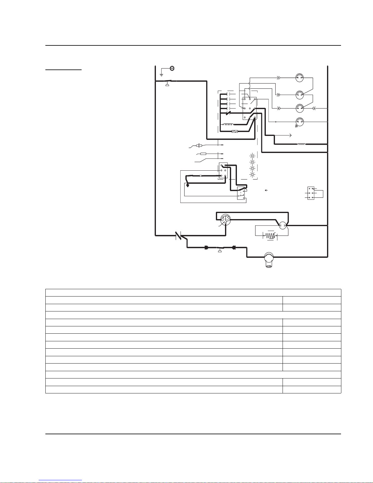
Section 6 Electrical System
Part No. 80-1100-3 6-5
Freeze Sequence
3. PRE-CHILL
To pre-chill the evaporator, the
compressor runs for 30 seconds prior
to water flow.
The water fill valve remains on until
the water level sensor closes for
three continuous seconds.
Figure 6-3. Self-Contained — Pre-Chill
Table 6-3. Self-Contained Models
3. Pre-Chill (30 Seconds)
Toggle Switch ICE
Bin Switch Closed
Control Board Relays
#1 Water Pump Open / OFF
#2 Water Fill Valve Closed / ON
#3 Harvest Solenoid Open / OFF
#4 Water Dump Valve Open / OFF
#5 Contactor Coil Closed / ON
Compressor ON
Condenser Fan Motor ON
Safety Controls (Which could stop ice machine operation)
High Pressure Cut-Out Closed
Main Fuse (On Control Board) Closed
*OVERLOAD
FAN CYCLE CONTROL
BIN SWITCH
TB35
TB33
(52)
(51)
(48)
CONTACTOR
CONTACTS
L1
(42)
(66)
(64)
ICE THICKNESS PROBE
WATER LEVEL PROBE
NOT USED
T
B35
HIGH PRES
CUTOUT
TB32
L1
(55)
RUN CAPACITOR
RUN CAPACITOR**
C
S
TB34
(53)
(47)
(85) (86)
COMPRESSOR
R
FAN MOTOR
(AIR COOLED ONLY)
R
R
(45)
(46) (50)
PTCR
BIN SWITCH LIGHT
HARVEST LIGHT/
SAFETY LIMIT CODE LIGHT
CLEAN LIGHT
WATER LEVEL
(49)
(63)
(62)
(66)
(65)
(69)
ICE
OFF
CLEAN
(67)
(68)
1F
1C
LOW D.C.
VOLTAGE
PLUG
(62)
1G
TOGGLE SWITCH
68
67
69
66
62
VIEW FOR WIRING
INTERNAL WORKING
VIEW
TB37
(74)
(59)
(73)
(56)
CONTACTOR
COIL
TERMINATES AT
PIN CONNECTION
TB3
0
TB3
0
TB30
TB30
L2 (N)
SEE SERIAL PLATE FOR VOLTAGE
(58)
FUSE (7A)
TRANS.
5
2
4
1
3
(61)
(60)
TB31
(76)
(98)
(57)
(99)
(75)
HARVEST
SOLENOID
DUMP
SOLENOID
(81)
WATER
PUMP
(77)
(80)
(21)
(22)
WATER
VALVE
TB30
TB30
(20)
SV1646-3
Page 62
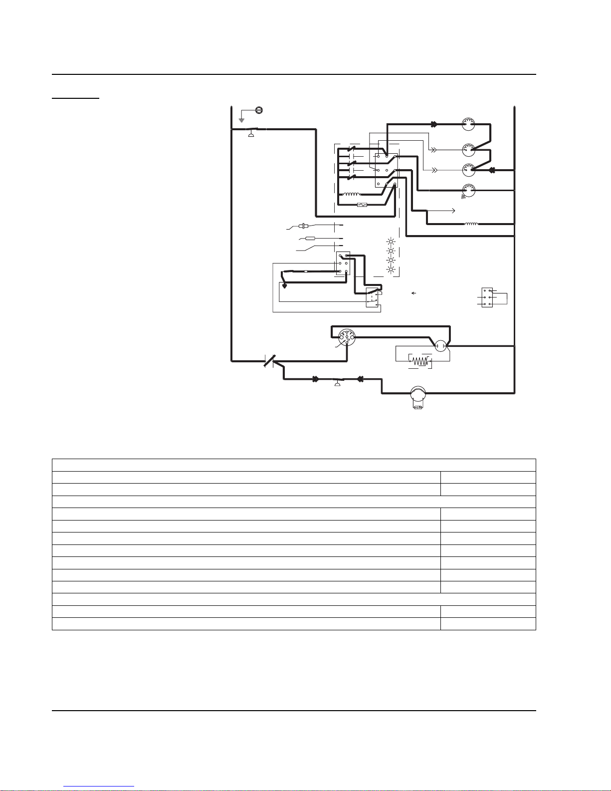
Electrical System Section 6
6-6 Part No. 80-1100-3
4. FREEZE
The water pump starts after the 30-
second pre-chill. An even flow of
water is directed across the
evaporator and into each cube cell,
where it freezes.
After six minutes the water inlet valve
is locked out and can not add
additional water.
When sufficient ice has formed, the
water flow (not the ice) contacts the
ice thickness probes. After
approximately 7 seconds of continual
contact, a harvest cycle is initiated.
NOTE: The ice machine cannot
initiate a harvest cycle until a 6minute freeze lock has expired.
Figure 6-4.
Self-Contained — Freeze
Table 6-4. Self-Contained Models
4. Freeze (Until 7 Seconds of Water Contact with Ice Thickness Probe)
Toggle Switch ICE
Bin Switch Closed
Control Board Relays
#1 Water Pump Closed / ON
#2 Water Fill Valve Cycles ON then OFF
#3 Harvest Solenoid Open / OFF
#4 Water Dump Valve Open / OFF
#5 Contactor Coil Closed / ON
Compressor ON
Condenser Fan Motor ON
Safety Controls (Which could stop ice machine operation)
High Pressure Cut-Out Closed
Main Fuse (On Control Board) Closed
*OVERLOAD
FAN CYCLE CONTROL
BIN SWITCH
TB35
TB33
(52)
(51)
(48)
CONTACTOR
CONTACTS
L1
(42)
(66)
(64)
ICE THICKNESS PROBE
WATER LEVEL PROBE
NOT USED
T
B35
HIGH PRES
CUTOUT
TB32
L1
(55)
RUN CAPACITOR
RUN CAPACITOR**
C
S
R
TB34
(53)
(47)
(85) (86)
COMPRESSOR
FAN MOTOR
(AIR COOLED ONLY)
R
R
(45)
(46) (50)
PTCR
BIN SWITCH LIGHT
HARVEST LIGHT/
SAFETY LIMIT CODE LIGHT
CLEAN LIGHT
WATER LEVEL
(49)
(63)
(62)
(66)
(65)
(69)
ICE
OFF
CLEAN
(67)
(68)
1F
1C
LOW D.C.
VOLTAGE
PLUG
(62)
1G
TOGGLE SWITCH
68
67
69
66
62
VIEW FOR WIRING
INTERNAL WORKING
VIEW
TB37
(74)
(59)
(73)
(56)
CONTACTOR
COIL
TERMINATES AT
PIN CONNECTION
TB3
0
TB3
0
TB30
TB30
L2 (N)
SEE SERIAL PLATE FOR VOLTAGE
(58)
FUSE (7A)
TRANS.
2
4
1
3
5
(61)
(60)
TB31
(76)
(98)
(57)
(99)
(75)
HARVEST
SOLENOID
DUMP
SOLENOID
(81)
WATER
PUMP
(77)
(80)
(21)
(22)
WATER
VALVE
TB30
TB30
(20)
SV1646-4
Page 63
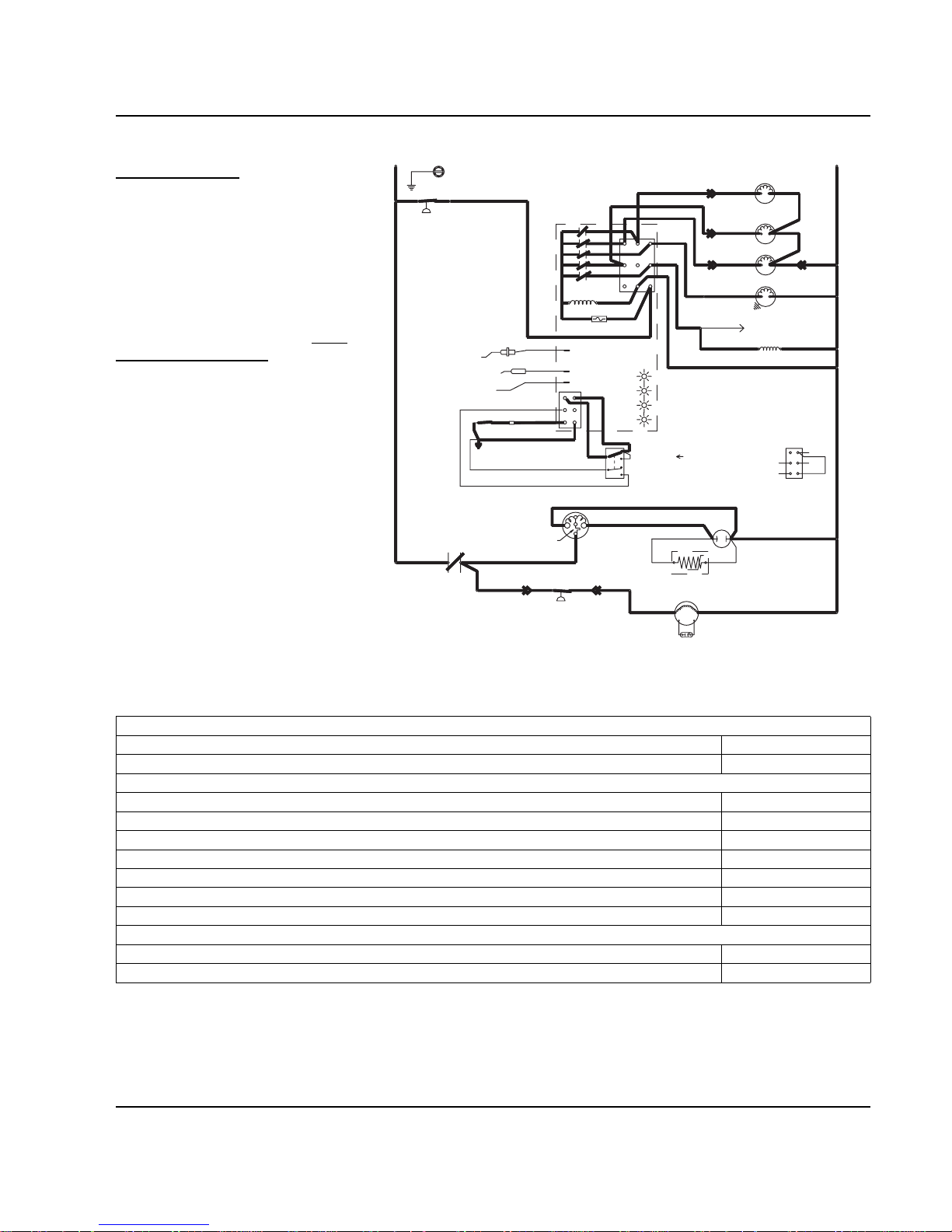
Section 6 Electrical System
Part No. 80-1100-3 6-7
Harvest Sequence
5. WATER PURGE
The water pump continues to run,
and the water dump valve energizes
for 45 seconds to purge the water in
the sump trough. The water fill valve
energizes (turns on) and deenergizes (turns off) strictly by time.
The water fill valve energizes for the
last 15 seconds of the 45-second
water purge. The water purge must
be at the factory setting of 45
seconds for the fill valve to energize
during the last 15 seconds of the
Water Purge. If set at less than 45
seconds, the water fill valve does not
energize during the water purge.
After the 45 second water purge, the
water fill valve, water pump and
dump valve de-energize. (Refer to
“Water Purge Adjustment” on Page
3-3 for details.) The harvest valve
also opens at the beginning of the
water purge to divert hot refrigerant
gas into the evaporator.
Figure 6-5.
Self-Contained — Water Purge
Table 6-5. Self-Contained Models
5. Water Purge (45 Seconds)
Toggle Switch ICE
Bin Switch Closed
Control Board Relays
#1 Water Pump Closed / ON
#2 Water Fill Valve Cycles OFF then ON
#3 Harvest Solenoid Closed / ON
#4 Water Dump Valve Closed / ON
#5 Contactor Coil Closed / ON
Compressor ON
Condenser Fan Motor ON
Safety Controls (Which could stop ice machine operation)
High Pressure Cut-Out Closed
Main Fuse (On Control Board) Closed
*OVERLOAD
FAN CYCLE CONTROL
BIN SWITCH
TB35
TB33
(52)
(51)
(48)
CONTACTOR
CONTACTS
L1
(42)
(66)
(64)
ICE THICKNESS PROBE
WATER LEVEL PROBE
NOT USED
T
B35
HIGH PRES
CUTOUT
TB32
L1
(55)
RUN CAPACITOR
RUN CAPACITOR**
C
S
R
TB34
(53)
(47)
(85) (86)
COMPRESSOR
FAN MOTOR
(AIR COOLED ONLY)
R
R
(45)
(46) (50)
PTCR
BIN SWITCH LIGHT
HARVEST LIGHT/
SAFETY LIMIT CODE LIGHT
CLEAN LIGHT
WATER LEVEL
(49)
(63)
(62)
(66)
(65)
(69)
ICE
OFF
CLEAN
(67)
(68)
1F
1C
LOW D.C.
VOLTAGE
PLUG
(62)
1G
TOGGLE SWITCH
68
67
69
66
62
VIEW FOR WIRING
INTERNAL WORKING
VIEW
TB37
(74)
(59)
(73)
(56)
CONTACTOR
COIL
TERMINATES AT
PIN CONNECTION
TB3
0
TB3
0
TB30
TB30
L2 (N)
SEE SERIAL PLATE FOR VOLTAGE
(58)
FUSE (7A)
TRANS.
2
4
1
3
5
(61)
(60)
TB31
(76)
(98)
(57)
(99)
(75)
HARVEST
SOLENOID
DUMP
SOLENOID
(81)
WATER
PUMP
(77)
(80)
(21)
WATER
VALVE
(22)
TB30
TB30
(20)
SV1646-5
Page 64

Electrical System Section 6
6-8 Part No. 80-1100-3
6. HARVEST
The harvest valve(s) remains open,
allowing refrigerant gas to warm the
evaporator. This ca uses the cubes to
slide, as a sheet, off the evaporator
and into the storage bin.
The sliding sheet of cubes swings the
water curtain out, opening the bin
switch. This momentary opening and
closing of the bin switch terminates
the Harvest Cycle and returns the ice
machine to the Freeze Cycle (steps
3-4).
Figure 6-6. Self-Contained — Harvest
Table 6-6. Self-Contained Models
6. Harvest (Until Bin Switch Activation)
Toggle Switch ICE
Bin Switch Closed
Control Board Relays
#1 Water Pump Open / OFF
#2 Water Fill Valve Open / OFF
#3 Harvest Solenoid Closed / ON
#4 Water Dump Valve Open / OFF
#5 Contactor Coil Closed / ON
Compressor ON
Condenser Fan Motor ON
Safety Controls (Which could stop ice machine operation)
High Pressure Cut-Out Closed
Main Fuse (On Control Board) Closed
*OVERLOAD
FAN CYCLE CONTROL
BIN SWITCH
TB35
TB33
(52)
(51)
(48)
CONTACTOR
CONTACTS
L1
(42)
(66)
(64)
ICE THICKNESS PROBE
WATER LEVEL PROBE
NOT USED
T
B35
HIGH PRES
CUTOUT
TB32
L1
(55)
RUN CAPACITOR
RUN CAPACITOR**
C
S
R
TB34
(53)
(47)
(85) (86)
COMPRESSOR
FAN MOTOR
(AIR COOLED ONLY)
R
R
(45)
(46) (50)
PTCR
BIN SWITCH LIGHT
HARVEST LIGHT/
SAFETY LIMIT CODE LIGHT
CLEAN LIGHT
WATER LEVEL
(49)
(63)
(62)
(66)
(65)
(69)
ICE
OFF
CLEAN
(67)
(68)
1F
1C
LOW D.C.
VOLTAGE
PLUG
(62)
1G
TOGGLE SWITCH
68
67
69
66
62
VIEW FOR WIRING
INTERNAL WORKING
VIEW
TB37
(74)
(59)
(73)
(56)
CONTACTOR
COIL
TERMINATES AT
PIN CONNECTION
TB3
0
TB3
0
TB30
TB30
L2 (N)
SEE SERIAL PLATE FOR VOLTAGE
(58)
FUSE (7A)
TRANS.
2
4
1
3
5
(61)
(60)
TB31
(76)
(98)
(57)
(99)
(75)
HARVEST
SOLENOID
DUMP
SOLENOID
(81)
WATER
PUMP
(77)
(80)
(21)
(22)
WATER
VALVE
TB30
TB30
(20)
SV1646-6
Page 65

Section 6 Electrical System
Part No. 80-1100-3 6-9
Automatic Shut-Off
7. AUTOMATIC SHUT-OFF
If the storage bin is full at the end of a
harvest cycle, the sheet of cubes fails
to clear the water curtain and holds it
open. After the water curtain is held
open for 7 seconds, the ice machine
shuts off.
The ice machine remains off until
enough ice is removed from the
storage bin to allow the sheet of
cubes to drop clear of the water
curtain. As the water curtain swings
back to the operating position, the bin
switch closes and the ice machine
restarts (steps 1-2).
NOTE: The ice machine must remain
off for 3 minutes before it can
automatically restart.
Figure 6-7. Self-Contained — Automatic Shut-Off
Table 6-7. Self-Contained Models
7. Automatic Shut-Off (Until Bin Switch Closes)
Toggle Switch ICE
Bin Switch Open
Control Board Relays
#1 Water Pump Open / OFF
#2 Water Fill Valve Open / OFF
#3 Harvest Solenoid Open / OFF
#4 Water Dump Valve Open / OFF
#5 Contactor Coil Open / OFF
Compressor OFF
Condenser Fan Motor OFF
Safety Controls (Which could stop ice machine operation)
High Pressure Cut-Out Closed
Main Fuse (On Control Board) Closed
*OVERLOAD
FAN CYCLE CONTROL
BIN SWITCH
TB35
TB33
(52)
(48)
CONTACTOR
CONTACTS
L1
(42)
(51)
(64)
(66)
ICE THICKNESS PROBE
WATER LEVEL PROBE
NOT USED
T
B35
HIGH PRES
CUTOUT
TB32
L1
(55)
TB3
0
RUN CAPACITOR
RUN CAPACITOR**
S
R
TB34
(47)
(86)
COMPRESSOR
C
(53)
(85)
FAN MOTOR
(AIR COOLED ONLY)
R
R
(45)
(46) (50)
PTCR
BIN SWITCH LIGHT
HARVEST LIGHT/
SAFETY LIMIT CODE LIGHT
CLEAN LIGHT
WATER LEVEL
(49)
(63)
(62)
(66)
(65)
(69)
(67)
ICE
OFF
CLEAN
(68)
1F
1C
LOW D.C.
VOLTAGE
PLUG
(62)
1G
TOGGLE SWITCH
68
67
69
66
62
VIEW FOR WIRING
INTERNAL WORKING
VIEW
TB37
(74)
(59)
(73)
(56)
CONTACTOR
COIL
TERMINATES AT
PIN CONNECTION
TB3
0
TB30
TB30
L2 (N)
SEE SERIAL PLATE FOR VOLTAGE
(58)
4
1
3
5
FUSE (7A)
TRANS.
2
(61)
(60)
TB31
(76)
(98)
(57)
(99)
(75)
HARVEST
SOLENOID
DUMP
SOLENOID
(81)
WATER
PUMP
(77)
(80)
(21)
(22)
WATER
VALVE
TB30
TB30
(20)
SV1646-7
Page 66

Electrical System Section 6
6-10 Part No. 80-1100-3
REMOTE MODELS
Initial Start-Up Or Start-Up After
Automatic Shut-Off
1. WATER PURGE
Before the compressor starts, the
water pump and water dump
solenoid are energized for 45
seconds to purge old water from the
ice machine. This ensures that the
ice-making cycle starts with fresh
water.
NOTE: The harvest valve and
harvest pressure regulating (HPR)
solenoid valve are also energized
during the water purge. In the case of
an initial refrigeration start-up, they
stay on for an additional 5 seconds
(50 seconds total).
Figure 6-8. Remote — Water Purge
Table 6-8. Remote Models
1. Water Purge (45 Seconds)
Toggle Switch ICE
Bin Switch Closed
Control Board Relays
#1 Water Pump Closed / ON
#2 Water Fill Valve Open / OFF
#3 Harvest Solenoid Closed / ON
Harvest Pressure Regulating (HPR) Solenoid Closed / ON
#4 Water Dump Valve Closed / ON
#5 Contactor Coil Open / OFF
Liquid Line Solenoid De-energized
Compressor OFF
Condenser Fan Motor OFF
Safety Controls (Which could stop ice machine operation)
High Pressure Cut-Out Closed
Main Fuse (On Control Board) Closed
TERMINATES AT
PIN CONNECTION
*OVERLOAD
BIN SWITCH
ICE THICKNESS PROBE
(F1)
TB33
(52)
(51)
(48)
T
B35
L1
(42)
CONTACTOR
CONTACTS
(66)
WATER LEVEL PROBE
NOT USED
(64)
TB32
T
B35
L1
(55)
HIGH PRES
CUTOUT
(74)
(73)
REMOTE
FAN MOTOR
RUN CAPACITOR
PTCR
TB34
(53)
REMOTE CONDENSER
(F2)
(45)
TB3
0
BIN SWITCH LIGHT
HARVEST LIGHT/
SAFETY LIMIT CODE LIGHT
RUN CAPACITOR
TOGGLE SWITCH
INTERNAL WORKING
VIEW
CLEAN LIGHT
WATER LEVEL
ICE
(68)
C
S
R
(46)
(49)
(47)
COMPRESSOR
(62)
(66)
(69)
(67)
OFF
CLEAN
1F
1C
LOW D.C.
VOLTAGE
PLUG
(63)
(65)
(62)
1G
R
R
(50)
TB3
0
68
67
69
66
62
(56)
TB3
0
TB3
0
CONTACTOR
COIL
VIEW FOR WIRING
(57)
4
(58)
1
3
FUSE (7A)
TRANS.
5
(61)
(60)
2
HARVEST
(80)
TB31
TB37
(76)
(98)
(59)
(99)
SOLENOID
DUMP
SOLENOID
WATER
PUMP
SOLENOID
TB3
0
TB3
0
(82)
(83)
(81)
(75)
LIQUID LINE
(77)
HPR
SOLENOID
(79)(78)
L2 (N)
SEE SERIAL PLATE FOR VOLTAGE
(22)(21)
WATER
VALVE
(20)
SV1648-1
Page 67

Section 6 Electrical System
Part No. 80-1100-3 6-11
2. REFRIGERATION SYSTEM
START-UP
The compressor, remote condenser
fan motor and liquid line solenoid
valve energize after the 45-second
water purge, and remain on
throughout the Freeze and Harvest
cycles.
The water fill valve is energized at
the same time as the compressor. It
remains on until the water level
sensor closes for 3 continuous
seconds.
The harvest valve and harvest
pressure regulating (HPR) solenoid
valve remain on for the first 5
seconds of the initial compressor
start-up.
NOTE: (The compressor and the
condenser fan motor are wired
through the contactor. Any time the
contactor coil is energized, these
components are supplied with
power.)
Figure 6-9. Remote — Refrigeration System Start-Up
Table 6-9. Remote Models
2. Refrigeration System Start-Up (5 Seconds)
Toggle Switch ICE
Bin Switch Closed
Control Board Relays
#1 Water Pump Open / OFF
#2 Water Fill Valve Closed / ON
#3 Harvest Solenoid Closed / ON
Harvest Pressure Regulating (HPR) Solenoid Closed / ON
#4 Water Dump Valve Open / OFF
#5 Contactor Coil Closed / ON
Liquid Line Solenoid Energized
Compressor ON
Condenser Fan Motor ON
Safety Controls (Which could stop ice machine operation)
High Pressure Cut-Out Closed
Main Fuse (On Control Board) Closed
TERMINATES AT
PIN CONNECTION
*OVERLOAD
BIN SWITCH
ICE THICKNESS PROBE
(F1)
TB33
(52)
(51)
(48)
T
B35
L1
(42)
CONTACTOR
CONTACTS
(66)
WATER LEVEL PROBE
NOT USED
(64)
TB32
T
B35
L1
(55)
HIGH PRES
CUTOUT
(74)
(73)
REMOTE
FAN MOTOR
RUN CAPACITOR
PTCR
TB34
(53)
REMOTE CONDENSER
(F2)
(45)
TB3
0
BIN SWITCH LIGHT
HARVEST LIGHT/
SAFETY LIMIT CODE LIGHT
RUN CAPACITOR
TOGGLE SWITCH
INTERNAL WORKING
VIEW
CLEAN LIGHT
WATER LEVEL
(68)
ICE
C
S
R
(46)
(49)
(47)
COMPRESSOR
(62)
(66)
(69)
(67)
OFF
CLEAN
1F
LOW D.C.
VOLTAGE
PLUG
(63)
(65)
(62)
1G
1C
R
R
(50)
TB3
0
68
67
69
66
62
(56)
COIL
VIEW FOR WIRING
TB3
0
CONTACTOR
TB3
0
(57)
4
(58)
1
3
FUSE (7A)
TRANS.
5
(61)
(60)
2
HARVEST
(80)
TB31
TB37
(76)
(98)
(59)
(99)
SOLENOID
SOLENOID
WATER
PUMP
SOLENOID
TB3
0
TB3
0
LIQUID LINE
(81)
(82)
(75)
DUMP
(83)
HPR
SOLENOID
L2 (N)
SEE SERIAL PLATE FOR VOLTAGE
(22)(21)
WATER
VALVE
(77)
(79)(78)
(20)
SV1648-2
Page 68

Electrical System Section 6
6-12 Part No. 80-1100-3
Freeze Sequence
3. PRE-CHILL
To pre-chill the evaporator, the
compressor runs for 30 seconds prior
to water flow.
NOTE: The water fill valve remains
on until the water level sensor closes
for three continuous seconds.
Figure 6-10. Remote — Pre-Chill
Table 6-10. Remote Models
3. Pre-Chill (30 Seconds)
Toggle Switch ICE
Bin Switch Closed
Control Board Relays
#1 Water Pump Open / OFF
#2 Water Fill Valve Closed / ON
#3 Harvest Solenoid Open / OFF
Harvest Pressure Regulating (HPR) Solenoid Open / OFF
#4 Water Dump Valve Open / OFF
#5 Contactor Coil Closed / ON
Liquid Line Solenoid Energized
Compressor ON
Condenser Fan Motor ON
Safety Controls (Which could stop ice machine operation)
High Pressure Cut-Out Closed
Main Fuse (On Control Board) Closed
TERMINATES AT
PIN CONNECTION
*OVERLOAD
BIN SWITCH
ICE THICKNESS PROBE
(F1)
TB33
(52)
(51)
(48)
T
B35
L1
(42)
CONTACTOR
CONTACTS
(66)
WATER LEVEL PROBE
NOT USED
(64)
TB32
T
B35
L1
(55)
HIGH PRES
CUTOUT
(74)
(73)
REMOTE
FAN MOTOR
RUN CAPACITOR
PTCR
TB34
(53)
REMOTE CONDENSER
(F2)
(45)
TB3
0
BIN SWITCH LIGHT
HARVEST LIGHT/
SAFETY LIMIT CODE LIGHT
RUN CAPACITOR
TOGGLE SWITCH
INTERNAL WORKING
VIEW
CLEAN LIGHT
WATER LEVEL
(68)
ICE
C
S
R
(46)
(49)
(47)
COMPRESSOR
(62)
(66)
(69)
(67)
OFF
CLEAN
1F
LOW D.C.
VOLTAGE
PLUG
(63)
(65)
(62)
1G
1C
R
R
(50)
TB3
0
68
67
69
66
62
(56)
COIL
VIEW FOR WIRING
TB3
0
CONTACTOR
TB3
0
(57)
4
(58)
1
3
FUSE (7A)
TRANS.
5
(61)
(60)
2
HARVEST
(80)
TB31
TB37
(76)
(98)
(99)
(75)
SOLENOID
DUMP
SOLENOID
(81)
WATER
PUMP
SOLENOID
TB3
0
TB3
0
(82)
(59)
(83)
LIQUID LINE
HPR
SOLENOID
L2 (N)
SEE SERIAL PLATE FOR VOLTAGE
(22)(21)
WATER
VALVE
(77)
(79)(78)
(20)
SV1648-3
Page 69
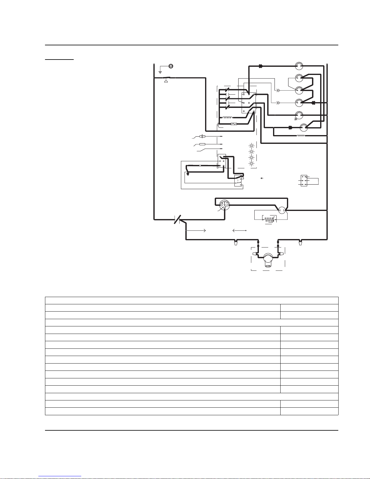
Section 6 Electrical System
Part No. 80-1100-3 6-13
4. FREEZE
The water pump starts after the 30-
second pre-chill. An even flow of
water is directed across the
evaporator and into each cube cell,
where it freezes.
After six minutes the water inlet valve
is locked out and can not add
additional water.
When sufficient ice has formed, the
water flow (not the ice) contacts the
ice thickness probes. After
approximately 7 seconds of continual
contact, a harvest cycle is initiated.
NOTE: The ice machine cannot
initiate a harvest cycle until a 6minute freeze lock has expired.
Figure 6-11. Remote — Freeze
Table 6-11. Remote Models
4. Freeze (Until 7 Seconds of Water Contact with Ice Thickness Probe)
Toggle Switch ICE
Bin Switch Closed
Control Board Relays
#1 Water Pump Closed / ON
#2 Water Fill Valve Cycles / ON then OFF
#3 Harvest Solenoid Open / OFF
Harvest Pressure Regulating (HPR) Solenoid Open / OFF
#4 Water Dump Valve Open / OFF
#5 Contactor Coil Closed / ON
Liquid Line Solenoid Energized
Compressor ON
Condenser Fan Motor ON
Safety Controls (Which could stop ice machine operation)
High Pressure Cut-Out Closed
Main Fuse (On Control Board) Closed
TERMINATES AT
PIN CONNECTION
*OVERLOAD
BIN SWITCH
ICE THICKNESS PROBE
(F1)
TB33
(52)
(51)
(48)
T
B35
L1
(42)
CONTACTOR
CONTACTS
(66)
(64)
WATER LEVEL PROBE
NOT USED
TB32
T
B35
L1
(55)
HIGH PRES
CUTOUT
(74)
(73)
REMOTE
FAN MOTOR
RUN CAPACITOR
PTCR
TB34
(53)
REMOTE CONDENSER
(F2)
(45)
TB3
0
BIN SWITCH LIGHT
HARVEST LIGHT/
SAFETY LIMIT CODE LIGHT
RUN CAPACITOR
TOGGLE SWITCH
INTERNAL WORKING
VIEW
CLEAN LIGHT
WATER LEVEL
(68)
ICE
C
S
R
(46)
(49)
(47)
COMPRESSOR
(62)
(66)
(69)
(67)
OFF
CLEAN
1F
LOW D.C.
VOLTAGE
PLUG
(63)
(65)
(62)
1G
1C
R
R
(50)
TB3
0
68
67
69
66
62
(56)
COIL
VIEW FOR WIRING
TB3
0
CONTACTOR
TB3
0
(57)
4
(58)
1
3
FUSE (7A)
TRANS.
5
(61)
(60)
2
HARVEST
(80)
TB31
TB37
(76)
(98)
(59)
(99)
SOLENOID
DUMP
SOLENOID
(81)
WATER
PUMP
SOLENOID
TB3
0
TB3
0
(82)
(83)
LIQUID LINE
(75)
HPR
SOLENOID
L2 (N)
SEE SERIAL PLATE FOR VOLTAGE
(22)(21)
WATER
VALVE
(77)
(79)(78)
(20)
SV1648-4
Page 70

Electrical System Section 6
6-14 Part No. 80-1100-3
Harvest Sequence
5. WATER PURGE
The water pump continues to run,
and the water dump valve energizes
for 45 seconds to purge the water in
the sump trough. The water fill valve
energizes (turns on) and deenergizes (turns off) strictly by time.
The water fill valve energizes for the
last 15 seconds of the 45-second
water purge. The water purge must
be at the factory setting of 45
seconds for the fill valve to energize
during the last 15 seconds of the
Water Purge. If set at less than 45
seconds the water fill valve does not
energize during the water purge.
NOTE: After the 45 second water
purge, the water fill valve, water
pump and dump valve de-energize.
(Refer to “Water Purge Adjustment”
on Page 3-3 for details.) The harvest
valve and HPR solenoid also open at
the beginning of the water purge to
divert hot refrigerant gas into the
evaporator.
Figure 6-12. Remote — Water Purge
Table 6-12. Remote Models
5. Water Purge (45 Seconds)
Toggle Switch ICE
Bin Switch Closed
Control Board Relays
#1 Water Pump Closed / ON
#2 Water Fill Valve Cycles / OFF then ON
#3 Harvest Solenoid Closed / ON
Harvest Pressure Regulating (HPR) Solenoid Closed / ON
#4 Water Dump Valve Closed / ON
#5 Contactor Coil Closed / ON
Liquid Line Solenoid Energized
Compressor ON
Condenser Fan Motor ON
Safety Controls (Which could stop ice machine operation)
High Pressure Cut-Out Closed
Main Fuse (On Control Board) Closed
TERMINATES AT
PIN CONNECTION
*OVERLOAD
BIN SWITCH
ICE THICKNESS PROBE
(F1)
TB33
(52)
(51)
(48)
T
B35
L1
(42)
CONTACTOR
CONTACTS
(66)
(64)
WATER LEVEL PROBE
NOT USED
TB32
T
B35
L1
(55)
HIGH PRES
CUTOUT
(74)
(73)
REMOTE
FAN MOTOR
RUN CAPACITOR
PTCR
TB34
(53)
REMOTE CONDENSER
(F2)
(45)
TB3
0
BIN SWITCH LIGHT
HARVEST LIGHT/
SAFETY LIMIT CODE LIGHT
RUN CAPACITOR
TOGGLE SWITCH
INTERNAL WORKING
VIEW
CLEAN LIGHT
WATER LEVEL
(68)
ICE
C
S
R
(46)
(49)
(47)
COMPRESSOR
(62)
(66)
(69)
(67)
OFF
CLEAN
1F
LOW D.C.
VOLTAGE
PLUG
(63)
(65)
(62)
1G
1C
R
R
(50)
TB3
0
68
67
69
66
62
(56)
COIL
VIEW FOR WIRING
TB3
0
CONTACTOR
TB3
0
(57)
4
(58)
1
3
FUSE (7A)
TRANS.
5
(61)
(60)
2
HARVEST
(80)
TB31
TB37
(76)
(98)
(99)
SOLENOID
DUMP
SOLENOID
(81)
WATER
PUMP
SOLENOID
TB3
0
TB3
0
(82)
(83)
(59)
(75)
LIQUID LINE
HPR
L2 (N)
SEE SERIAL PLATE FOR VOLTAGE
(22)(21)
WATER
VALVE
(77)
(79)(78)
SOLENOID
(20)
SV1648-5
Page 71

Section 6 Electrical System
Part No. 80-1100-3 6-15
6. HARVEST
The harvest valve(s) and HPR
solenoid valve remain open, allowing
refrigerant gas to warm the
evaporator. This ca uses the cubes to
slide, as a sheet, off the evaporator
and into the storage bin.
The sliding sheet of cubes swings the
water curtain out, opening the bin
switch. This momentary opening and
closing of the bin switch terminates
the Harvest Cycle and returns the ice
machine to the Freeze Cycle (steps
3-4).
Figure 6-13. Remote — Harvest
Table 6-13. Remote Models
6. Harvest (Until Bin Switch Activation)
Toggle Switch ICE
Bin Switch Closed
Control Board Relays
#1 Water Pump Open / OFF
#2 Water Fill Valve Open / OFF
#3 Harvest Solenoid Closed / ON
Harvest Pressure Regulating (HPR) Solenoid Closed / ON
#4 Water Dump Valve Open / OFF
#5 Contactor Coil Closed / ON
Liquid Line Solenoid Energized
Compressor ON
Condenser Fan Motor ON
Safety Controls (Which could stop ice machine operation)
High Pressure Cut-Out Closed
Main Fuse (On Control Board) Closed
TERMINATES AT
PIN CONNECTION
*OVERLOAD
BIN SWITCH
ICE THICKNESS PROBE
(F1)
TB33
(52)
(51)
(48)
T
B35
L1
(42)
CONTACTOR
CONTACTS
(66)
(64)
WATER LEVEL PROBE
NOT USED
TB32
T
B35
L1
(55)
HIGH PRES
CUTOUT
(73)
(74)
REMOTE
FAN MOTOR
RUN CAPACITOR
PTCR
TB34
(53)
REMOTE CONDENSER
(F2)
(45)
TB3
0
BIN SWITCH LIGHT
HARVEST LIGHT/
SAFETY LIMIT CODE LIGHT
RUN CAPACITOR
TOGGLE SWITCH
INTERNAL WORKING
VIEW
CLEAN LIGHT
WATER LEVEL
(68)
ICE
C
S
R
(46)
(49)
(47)
COMPRESSOR
(62)
(66)
(69)
(67)
OFF
CLEAN
1F
LOW D.C.
VOLTAGE
PLUG
(63)
(65)
(62)
1G
1C
R
R
(50)
TB3
0
68
67
69
66
62
(56)
COIL
VIEW FOR WIRING
TB3
0
CONTACTOR
TB3
0
(57)
4
(58)
1
3
FUSE (7A)
TRANS.
5
(61)
(60)
2
HARVEST
(80)
TB31
TB37
(76)
(98)
(59)
(99)
SOLENOID
DUMP
SOLENOID
WATER
PUMP
SOLENOID
TB3
0
TB3
0
(82)
(83)
(81)
(75)
LIQUID LINE
HPR
SOLENOID
L2 (N)
SEE SERIAL PLATE FOR VOLTAGE
(22)(21)
WATER
VALVE
(77)
(79)
(78)
(20)
SV1648-6
Page 72
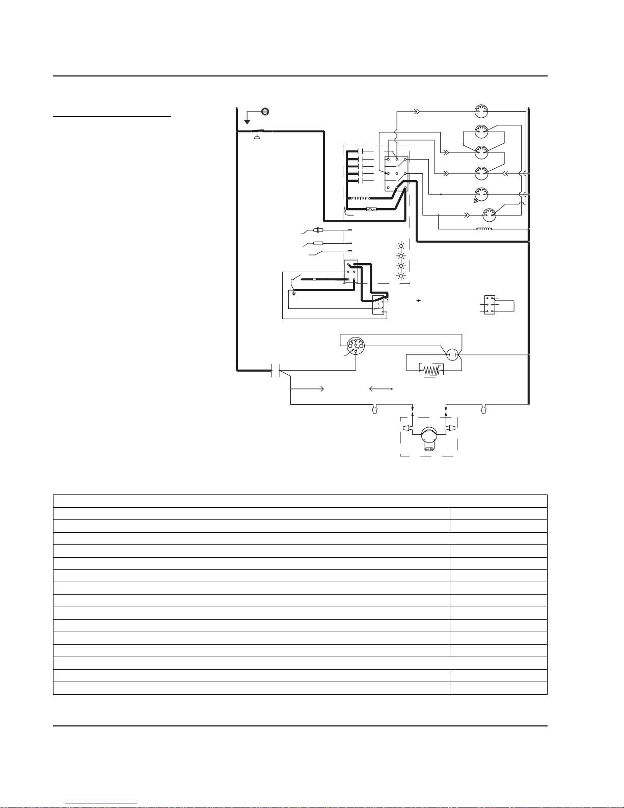
Electrical System Section 6
6-16 Part No. 80-1100-3
Automatic Shut-Off
7. AUTOMATIC SHUT-OFF
If the storage bin is full at the end of a
harvest cycle, the sheet of cubes fails
to clear the water curtain and holds it
open. After the water curtain is held
open for 7 seconds, the ice machine
shuts off.
The ice machine remains off until
enough ice is removed from the
storage bin to allow the sheet of
cubes to drop clear of the water
curtain. As the water curtain swings
back to the operating position, the bin
switch closes and the ice machine
restarts.
NOTE: The ice machine must remain
off for 3 minutes before it can
automatically restart.
Figure 6-14. Remote — Automatic Shut-Off
Table 6-14. Remote Models
7. Automatic Shut-Off (Until Bin Switch Closes)
Toggle Switch ICE
Bin Switch Open
Control Board Relays
#1 Water Pump Open / OFF
#2 Water Fill Valve Open / OFF
#3 Harvest Solenoid Open / OFF
Harvest Pressure Regulating (HPR) Solenoid Open / OFF
#4 Water Dump Valve Open / OFF
#5 Contactor Coil Open / OFF
Liquid Line Solenoid De-energized
Compressor ON
Condenser Fan Motor ON
Safety Controls (Which could stop ice machine operation)
High Pressure Cut-Out Closed
Main Fuse (On Control Board) Closed
TERMINATES AT
PIN CONNECTION
*OVERLOAD
BIN SWITCH
ICE THICKNESS PROBE
(F1)
TB33
(52)
(51)
(48)
T
B35
L1
(42)
CONTACTOR
CONTACTS
(66)
(64)
WATER LEVEL PROBE
NOT USED
TB32
T
B35
L1
(55)
HIGH PRES
CUTOUT
(74)
(73)
REMOTE
FAN MOTOR
RUN CAPACITOR
PTCR
TB34
(53)
REMOTE CONDENSER
(F2)
(45)
TB3
0
BIN SWITCH LIGHT
HARVEST LIGHT/
SAFETY LIMIT CODE LIGHT
RUN CAPACITOR
TOGGLE SWITCH
INTERNAL WORKING
VIEW
CLEAN LIGHT
WATER LEVEL
(68)
ICE
C
S
R
(46)
(49)
(47)
COMPRESSOR
(62)
(66)
(69)
(67)
OFF
CLEAN
1F
LOW D.C.
VOLTAGE
PLUG
(63)
(65)
(62)
1G
1C
R
R
(50)
TB3
0
68
67
69
66
62
(56)
COIL
VIEW FOR WIRING
TB3
0
CONTACTOR
TB3
0
(57)
4
(58)
1
3
FUSE (7A)
TRANS.
5
(61)
(60)
2
HARVEST
(80)
TB31
TB37
(76)
(98)
(59)
(99)
(75)
SOLENOID
DUMP
SOLENOID
(81)
WATER
PUMP
LIQUID LINE
SOLENOID
TB3
0
TB3
0
(82)
(83)
HPR
SOLENOID
L2 (N)
SEE SERIAL PLATE FOR VOLTAGE
(22)(21)
WATER
VALVE
(77)
(79)(78)
(20)
SV1648-7
Page 73

Section 6 Electrical System
Part No. 80-1100-3 6-17
Wiring Diagrams
The following pages contain electrical wiring diagrams. Be sure you are referring to the correct diagram for the ice
machine which you are servicing.
WIRING DIAGRAM LEGEND
The following symbols are used on all of the wiring diagrams:
* Internal Compressor Overload
(Some models have external compressor overloads)
** Fan Motor Run Capacitor
(Some models do not incorporate fan motor run capacitor)
TB Terminal Board Connection
(Terminal board numbers are printed on the actual terminal board)
( ) Wire Number Designation
(The number is marked at each end of the wire)
—>>— Multi-Pin Connection
(Electrical Box Side) —>>— (Compressor Compartment Side)
!
Warning
Always disconnect power before working on
electrical circuitry.
Page 74
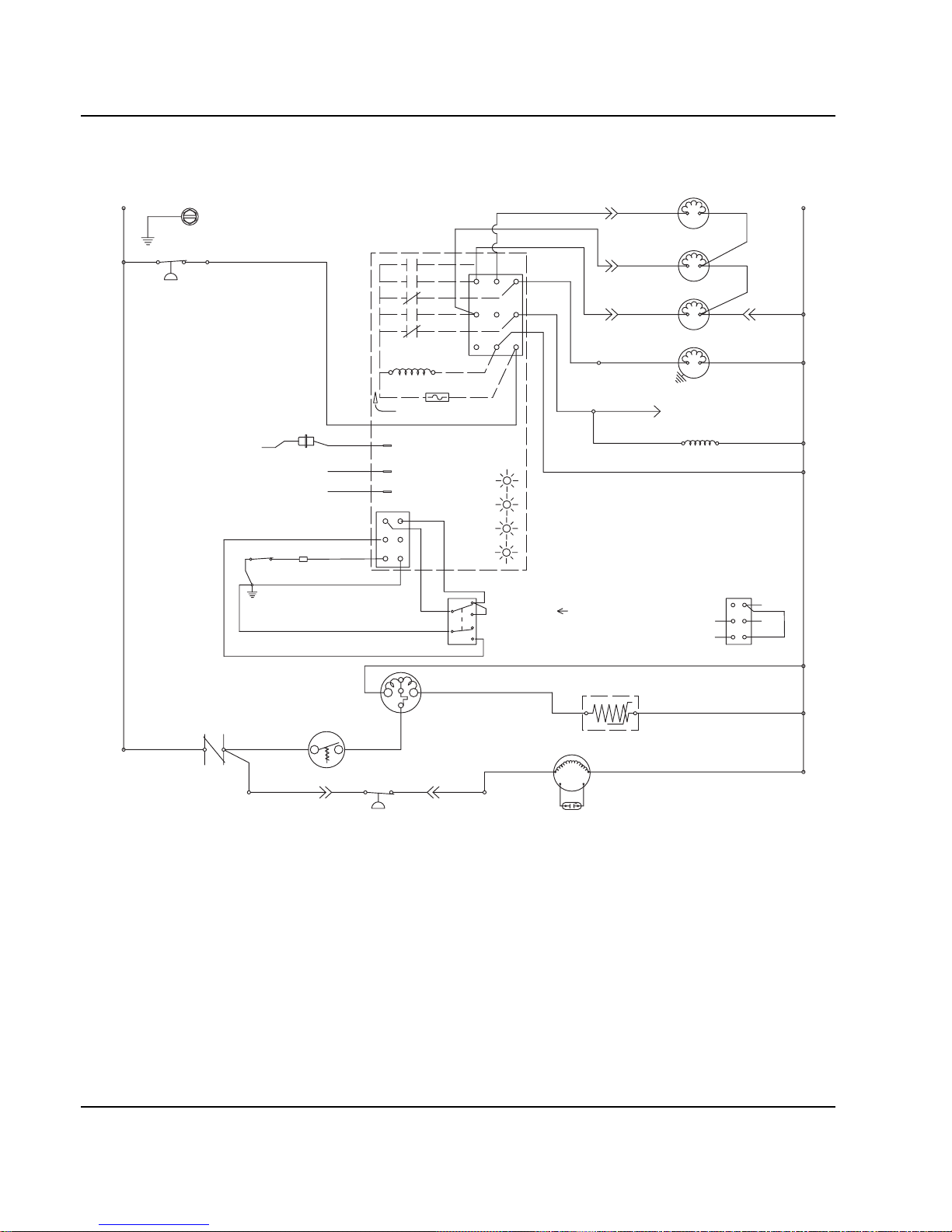
Electrical System Section 6
6-18 Part No. 80-1100-3
Q200/Q280/Q320 - SELF CONTAINED - 1 PHASE WITH TERMINAL BOARD
C
S
R
TB31
TB37
TB32
TB35
L1
TB34
(53)
TB33
(52)
(51)
(48)
(50)
(49)
(47)
(55)
(61)
(77)
(76)
(60)
(98)
(57)
(74)
(58)
(59)
(73)
(99)
(85) (86)
1F
3
1
2
4
FUSE (7A)
TRANS.
(56)
ICE THICKNESS PROBE
(75)
HARVEST
SOLENOID
DUMP
SOLENOID
(81)
(80)
WATER
PUMP
TB3
0
TB3
0
TB3
0
TB3
0
CONTACTOR
COIL
HIGH PRES
CUTOUT
BIN SWITCH LIGHT
HARVEST LIGHT/
SAFETY LIMIT CODE LIGHT
T
B35
TB3
0
CONTACTOR
CONTACTS
L1
(42)
COMPRESSOR
FAN CYCLE CONTROL
FAN MOTOR
(AIR COOLED ONLY)
RUN CAPACITOR**
L2 (N)
SEE SERIAL PLATE FOR VOLTAGE
CAUTION: DISCONNECT POWER BEFORE WORKING
ON ELECTRICAL CIRCUITRY.
DIAGRAM SHOWN DURING FREEZE CYCLE
TERMINATES AT
PIN CONNECTION
PTCR
TB3
0
TB3
0
LOW D.C.
VOLTAGE
PLUG
(64)
(63)
BIN SWITCH
(62)
(66)
(65)
(69)
(67)
(68)
TOGGLE SWITCH
68
67
69
66
62
ICE
OFF
CLEAN
(66)
(62)
VIEW FOR WIRING
INTERNAL WORKING
VIEW
*OVERLOAD
CLEAN LIGHT
1C
WATER LEVEL LIGHT
WATER LEVEL PROBE
5
(21) (22)
WATER
VALVE
1G
NOT USED
(20)
SV1654
Page 75

Section 6 Electrical System
Part No. 80-1100-3 6-19
Q280/Q370 - SELF CONTAINED - 1 PHASE WITHOUT TERMINAL BOARD
5
2
1
4
START
CAPACITOR
POTENTIAL
RELAY
C
S
R
COMPRESSOR
TERMINAL LAYOUT
VIEWED FROM END
OF COMPRESSOR
CAUTION: DISCONNECT POWER BEFORE WORKING
ON ELECTRICAL CIRCUITRY.
DIAGRAM SHOWN DURING FREEZE CYCLE
SAFETY LIMIT CODE LIGHT
HARVEST LIGHT/
WATER LEVEL
CLEAN LIGHT
BIN SWITCH LIGHT
CLEAN
OFF
ICE
(68)
(69)
(62)
(49)
(47)
COMPRESSOR
OVERLOAD INTERNAL
{230V 50/60 HZ}
R
C
S
(86)(85)
(51)
(48)
CONTACTOR
CONTACTS
(42)
L1
FAN CYCLE CONTROL
RUN CAPACITOR**
FAN MOTOR
(AIR COOLED ONLY)
(50)
62
66
VIEW FOR
WIRING
67
68
69
SEE SERIAL PLATE FOR VOLTAGE
L2 (N)
(74)
TERMINATES AT
PIN CONNECTION
(59)
(58)
(56)
(98)
DUMP
SOLENOID
(57)
(81)
(99)
(75)
(80)
(76)
HARVEST
SOLENOID
(77)
WATER
VALVE
(21)
(22)
(60)
(61)
(55)
HIGH PRES
CUTOUT
L
1
WATER LEVEL PROBE
NOT USED
ICE THICKNESS PROBE
LOW D.C.
VOLTAGE
PLUG
1G
1F
1C
BIN SWITCH
(64)
(66)
(66)
(67)
(63)
(62)
CONTACTOR
COIL
WATER
PUMP
FUSE (7A)
TRANS.
5
3
1
4
2
(65)
(89)
(88)
(20)
(46)
(44)
(45)
SV3018
Page 76

Electrical System Section 6
6-20 Part No. 80-1100-3
Q320 - SELF CONTAINED - 1 PHASE WITHOUT TERMINAL BOARD
R
R
C
S
R
L
1
*OVERLOAD
OVERLOAD
(51)
(48)
(45)
(46)
(49)
(47)
(48)
(50)
(50)
(49)
(47)
(55)
(61)
(20)
(76)
(60)
(98)
(57)
(74)
(58)
(59)
(99)
(85)
(86)
1F
1C
4
2
1
5
FUSE (7A)
TRANS.
(56)
ICE THICKNESS PROBE
(75)
HARVEST
SOLENOID
DUMP
SOLENOID
(81)
(22)
WATER
PUMP
CONTACTOR
COIL
HIGH PRES
CUTOUT
BIN SWITCH LIGHT
HARVEST LIGHT/
SAFETY LIMIT CODE LIGHT
LOW D.C.
VOLTAGE
PLUG
CONTACTOR
CONTACTS
L1
(42)
COMPRESSOR
COMPRESSOR
RUN CAPACITOR
FAN CYCLE CONTROL
FAN MOTOR
(AIR COOLED ONLY)
RUN CAPACITOR**
L2 (N)
SEE SERIAL PLATE FOR VOLTAGE
CAUTION: DISCONNECT POWER BEFORE WORKING
ON ELECTRICAL CIRCUITRY.
DIAGRAM SHOWN DURING FREEZE CYCLE
TERMINATES AT
PIN CONNECTION
PTCR
PTCR
(64)
(63)
BIN SWITCH
(62)
(66)
(65)
(69)
(67)
(68)
TOGGLE SWITCH
68
67
69
66
62
ICE
OFF
CLEAN
(62)
VIEW FOR WIRING
CLEAN LIGHT
WATER LEVEL
WATER LEVEL PROBE
(77)
(80)
WATER
VALVE
3
1G
NOT USED
(89)
(88)
(21)
SV2070
Page 77
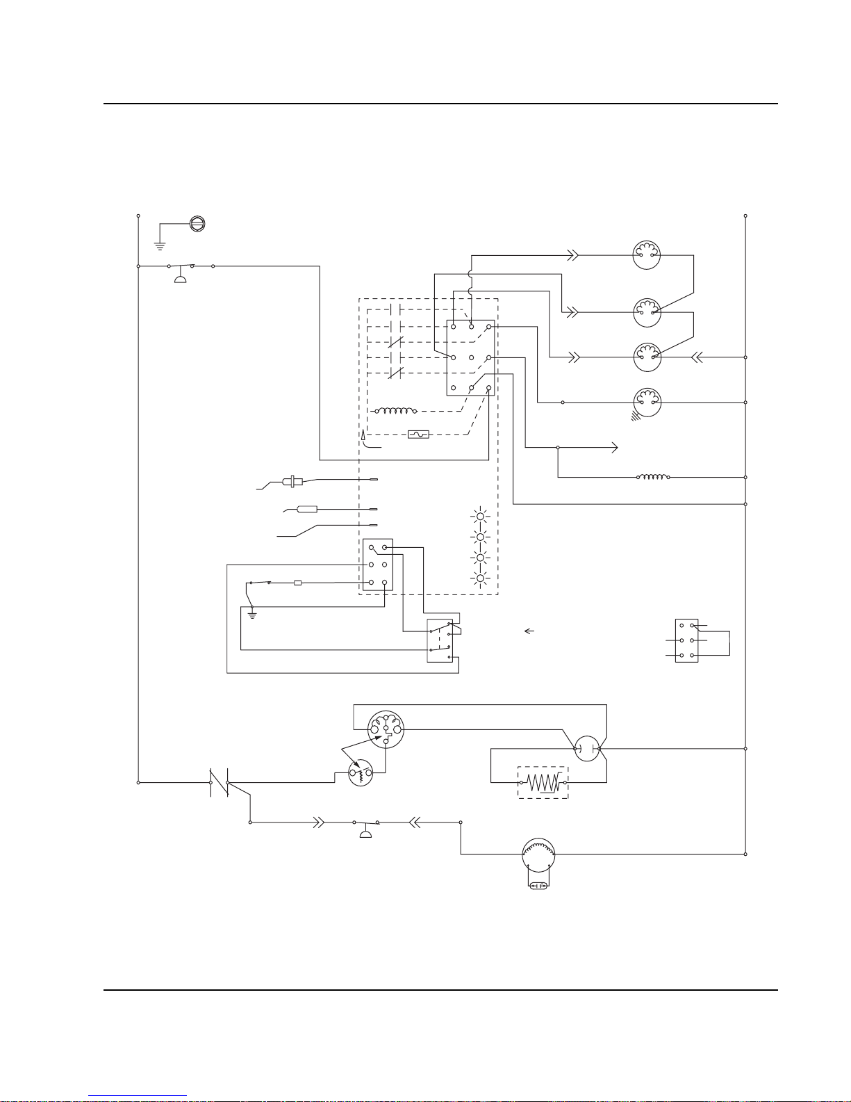
Section 6 Electrical System
Part No. 80-1100-3 6-21
Q420/Q450/Q600/Q800/Q1000 - SELF CONTAINED 1 PHASE WITH TERMINAL BOARD
R
R
C
S
R
TB31
TB37
TB32
T
B35
L1
TB34
*OVERLOAD
(53)
TB33
(52)
(51)
(48)
(45)
(46) (50)
(49)
(47)
(55)
(61)
(21)
(76)
(60)
(98)
(57)
(74)
(58)
(59)
(73)
(99)
(85) (86)
1F
1C
4
1
3
5
FUSE (7A)
TRANS.
(56)
ICE THICKNESS PROBE
(75)
HARVEST
SOLENOID
DUMP
SOLENOID
(81)
(22)
WATER
PUMP
TB30
TB30
TB30
TB30
CONTACTOR
COIL
HIGH PRES
CUTOUT
BIN SWITCH LIGHT
HARVEST LIGHT/
SAFETY LIMIT CODE LIGHT
LOW D.C.
VOLTAGE
PLUG
TB35
TB3
0
CONTACTOR
CONTACTS
L1
(42)
COMPRESSOR
RUN CAPACITOR
FAN CYCLE CONTROL
FAN MOTOR
(AIR COOLED ONLY)
RUN CAPACITOR**
L2 (N)
SEE SERIAL PLATE FOR VOLTAGE
CAUTION: DISCONNECT POWER BEFORE WORKING
ON ELECTRICAL CIRCUITRY.
DIAGRAM SHOWN DURING FREEZE CYCLE
TERMINATES AT
PIN CONNECTION
PTCR
TB3
0
(64)
(63)
BIN SWITCH
(62)
(66)
(65)
(69)
(67)
(68)
TOGGLE SWITCH
68
67
69
66
62
ICE
OFF
CLEAN
(66)
(62)
VIEW FOR WIRING
INTERNAL WORKING
VIEW
CLEAN LIGHT
WATER LEVEL LIGHT
WATER LEVEL PROBE
(77)
(80)
WATER
VALVE
2
1G
NOT USED
(20)
SV1646
Page 78
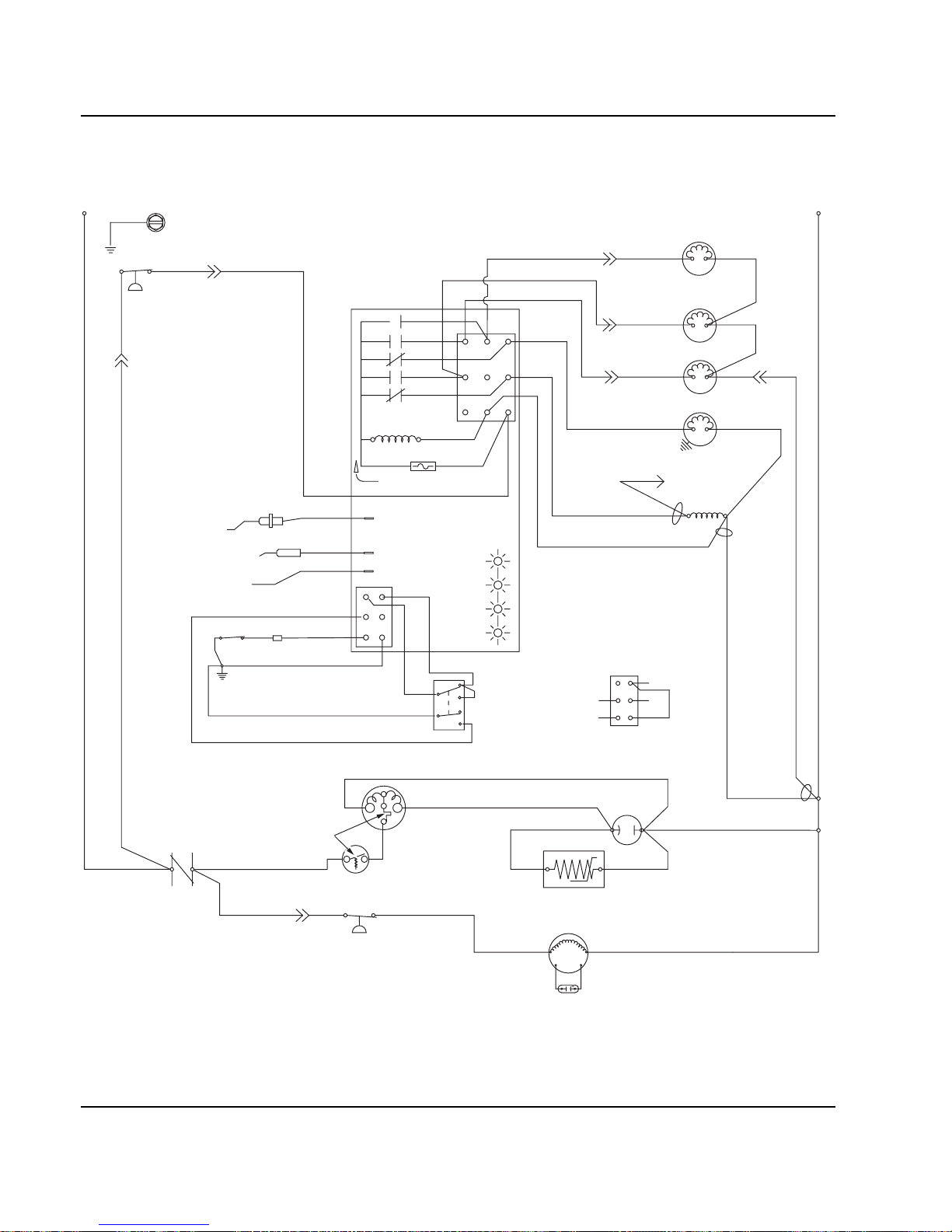
Electrical System Section 6
6-22 Part No. 80-1100-3
Q420/Q450/Q600/Q800/Q1000 - SELF CONTAINED 1 PHASE WITHOUT TERMINAL BOARD
*Overload
C
S
R
L
1
(51)
(48)
(45)
(46)
(49)
(50)
(50)
(47)
(55)
(61)
(20) (21)
(76)
(60)
(98)
(57)
(74)
(58)
(59)
(99)
(85)
(86)
1F
1C
4
2
1
5
FUSE (7A)
TRANS.
(56)
ICE THICKNESS PROBE
(75)
HARVEST
SOLENOID
DUMP
SOLENOID
(81)
(22)
WATER
PUMP
CONTACTOR
COIL
HIGH PRES
CUTOUT
BIN SWITCH LIGHT
HARVEST LIGHT/
SAFETY LIMIT CODE LIGHT
LOW D.C.
VOLTAGE
PLUG
CONTACTOR
CONTACTS
L1
(42)
COMPRESSOR
FAN CYCLE CONTROL
FAN MOTOR
(AIR COOLED ONLY)
RUN CAPACITOR**
L2 (N
)
SEE SERIAL PLATE FOR VOLTAGE
CAUTION: DISCONNECT POWER BEFORE WORKING
ON ELECTRICAL CIRCUITRY.
DIAGRAM SHOWN DURING FREEZE CYCLE
TERMINATES AT
PIN CONNECTION
PTCR
(64)
(63)
BIN SWITCH
(62)
(66)
(65)
(69)
(67)
(68)
TOGGLE SWITCH
68
67
69
66
62
ICE
OFF
CLEAN
(62)
VIEW FOR WIRING
CLEAN LIGHT
WATER LEVEL
WATER LEVEL PROBE
(77)
(80)
WATER
VALVE
3
1G
NOT USED
(89)
(88)
SV2071
Page 79
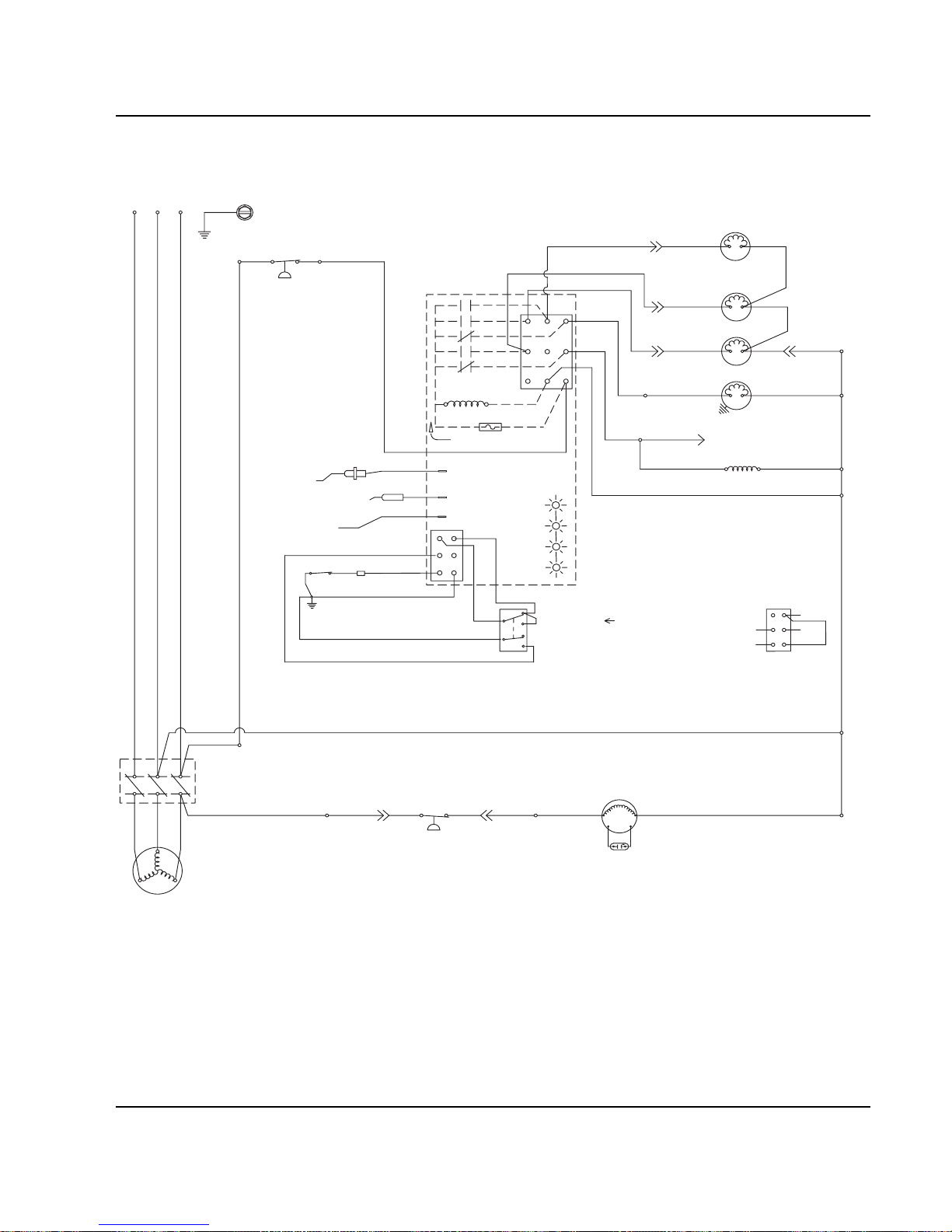
Section 6 Electrical System
Part No. 80-1100-3 6-23
Q800/Q1000 - SELF CONTAINED - 3 PHASE WITH TERMINAL BOARD
TB31
TB37
(77)
(76)
(98)
(74)
(59)
(73)
(99)
(85)
(86)
(75)
HARVEST
SOLENOID
DUMP
SOLENOID
(81)
(80)
WATER
PUMP
TB3
0
TB3
0
TB3
0
CONTACTOR
COIL
TB3
0
FAN CYCLE CONTROL
FAN MOTOR
(AIR COOLED ONLY)
RUN CAPACITOR**
SEE SERIAL PLATE FOR VOLTAGE
CAUTION: DISCONNECT POWER BEFORE WORKING
ON ELECTRICAL CIRCUITRY.
DIAGRAM SHOWN DURING FREEZE CYCLE
TERMINATES AT
PIN CONNECTION
(61)
(60)
(57)
(58)
1F
1C
4
1
3
5
FUSE (7A)
TRANS.
(56)
ICE THICKNESS PROBE
TB3
0
BIN SWITCH LIGHT
HARVEST LIGHT/
SAFETY LIMIT CODE LIGHT
LOW D.C.
VOLTAGE
PLUG
TB32
TB35
TB34
(53)
TB33
(52)
HIGH PRES
CUTOUT
L1
(96)
(42)
COMPRESSOR
L3
L2
L1
L2
L
3
TB35
T2
T3
T1
(55)
TB3
0
(64)
(63)
BIN SWITCH
(62)
(66)
(65)
(69)
(67)
(68)
TOGGLE SWITCH
68
67
69
66
62
ICE
OFF
CLEAN
(66)
(62)
VIEW FOR WIRING
INTERNAL WORKING
VIEW
CLEAN LIGHT
WATER LEVEL LIGHT
(21)
(22)
WATER
VALVE
WATER LEVEL PROBE
2
1G
NOT USED
(20)
SV1647a
Page 80
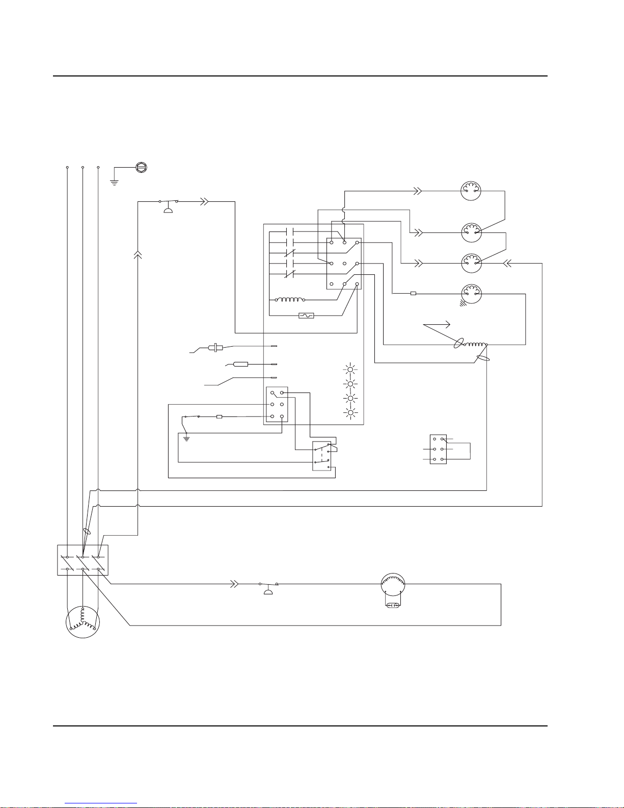
Electrical System Section 6
6-24 Part No. 80-1100-3
Q800/Q1000 - SELF CONTAINED - 3 PHASE WITHOUT TERMINAL BOARD
L1L2L3
(51)
(55)
(61)
(20) (21)
(76)
(60)
(98)
(57)
(74)
(58)
(59)
(99)
(85)
(86)
1F
1C
4
2
1
5
FUSE (7A)
TRANS.
(56)
ICE THICKNESS PROBE
(75)
HARVEST
SOLENOID
DUMP
SOLENOID
(81)
(22)
WATER
PUMP
CONTACTOR
COIL
HIGH PRES
CUTOUT
BIN SWITCH LIGHT
HARVEST LIGHT/
SAFETY LIMIT CODE LIGHT
LOW D.C.
VOLTAGE
PLUG
CONTACTOR
CONTACTS
L1
L2
L3
T2
T1T3
FAN CYCLE CONTROL
FAN MOTOR
(AIR COOLED ONLY)
RUN CAPACITOR**
SEE SERIAL PLATE FOR VOLTAGE
CAUTION: DISCONNECT POWER BEFORE WORKING
ON ELECTRICAL CIRCUITRY.
DIAGRAM SHOWN DURING FREEZE CYCLE
TERMINATES AT
PIN CONNECTION
(64)
(63)
BIN SWITCH
(62)
(66)
(65)
(69)
(67)
(68)
TOGGLE SWITCH
68
67
69
66
62
ICE
OFF
CLEAN
(62)
VIEW FOR WIRING
CLEAN LIGHT
WATER LEVEL
WATER LEVEL PROBE
(77)
(80)
WATER
VALVE
3
1G
NOT USED
(89)
(88)
(42)
SV2072
Page 81

Section 6 Electrical System
Part No. 80-1100-3 6-25
Q1300/Q1800 - SELF CONTAINED - 1 PHASE WITH TERMINAL BOARD
R
R
C
S
R
TB31
TB37
TB32
TB35
L1
TB34
*OVERLOAD
(53)
TB33
(52)
(51)
(48)
(45)
(46) (50)
(49)
(47)
(55)
(61)
(77)
(76)
(60)
(98)
(57)
(74)
(58)
(59)
(73)
(99)
(85) (86)
1F
1C
4
1
3
5
FUSE (7A)
TRANS.
(56)
ICE THICKNESS PROBE
(75)
LH HARVEST
SOLENOID
DUMP
SOLENOID
(81)
(80)
WATER
PUMP
TB3
0
TB3
0
TB3
0
TB3
0
CONTACTOR
COIL
HIGH PRES
CUTOUT
BIN SWITCH LIGHT
HARVEST LIGHT/
SAFETY LIMIT CODE LIGHT
LOW D.C.
VOLTAGE
PLUG
TB35
TB3
0
CRANKCASE HEATER
(94)
(95)
T
B35
TB3
0
CONTACTOR
CONTACTS
CONTACTOR
CONTACTS
L2
L1
(96)
(42)
COMPRESSOR
RUN CAPACITOR
FAN CYCLE CONTROL
FAN MOTOR
(AIR COOLED ONLY)
RUN CAPACITOR**
L2(N)
SEE SERIAL PLATE FOR VOLTAGE
CAUTION: DISCONNECT POWER BEFORE WORKING
ON ELECTRICAL CIRCUITRY.
DIAGRAM SHOWN DURING FREEZE CYCLE
TERMINATES AT
PIN CONNECTION
PTCR
(44)
(64)
(63)
BIN SWITCH
(62)
(66)
(65)
(69)
(67)
(68)
TOGGLE SWITCH
68
67
69
66
62
ICE
OFF
CLEAN
(66)
(62)
VIEW FOR WIRING
INTERNAL WORKING
VIEW
WATER
VALVE
(21)
(22)
CLEAN LIGHT
WATER LEVEL LIGHT
WATER LEVEL PROBE
2
(87)
(88)
RH HARVEST
SOLENOID
1G
AUCS DISPENSE TIME
(20)
SV1652
Page 82

Electrical System Section 6
6-26 Part No. 80-1100-3
Q1300/Q1600/Q1800 - SELF CONTAINED - 1 PHASE WITHOUT TERMINAL BOARD
C
S
R
L1
*OVERLOAD
(51)
(48)
(95)
(45)
(46)
(49)
(47)
(50)
(94)
(96)
(55)
(61)
(20) (21)
(76)
(60)
(98)
(57)
(74)
(58)
(59)
(99)
(85)
(86)
1F
1C
4
2
1
5
FUSE (7A)
TRANS.
(56)
ICE THICKNESS PROBE
(75)
HARVEST
SOLENOID
DUMP
SOLENOID
(81)
(22)
WATER
PUMP
CONTACTOR
COIL
HIGH PRES
CUTOUT
BIN SWITCH LIGHT
HARVEST LIGHT/
SAFETY LIMIT CODE LIGHT
LOW D.C.
VOLTAGE
PLUG
CONTACTOR
CONTACTS
CONTACTOR
CONTACTS
L1 L2
COMPRESSOR
CRANKCASE HEATER
RUN CAPACITOR
FAN CYCLE CONTROL
FAN MOTOR
(AIR COOLED ONLY)
RUN CAPACITOR**
L2 (N
)
SEE SERIAL PLATE FOR VOLTAGE
CAUTION: DISCONNECT POWER BEFORE WORKING
ON ELECTRICAL CIRCUITRY.
DIAGRAM SHOWN DURING FREEZE CYCLE
TERMINATES AT
PIN CONNECTION
PTCR
(64)
(63)
BIN SWITCH
(62)
(66)
(65)
(69)
(67)
(68)
TOGGLE SWITCH
68
67
69
66
62
ICE
OFF
CLEAN
(62)
VIEW FOR WIRING
CLEAN LIGHT
WATER LEVEL LIGHT
WATER LEVEL PROBE
AUCS DISPENSE TIME
(77)
(80)
WATER
VALVE
3
1G
(89)
(88)
(42)
SV2075
Page 83
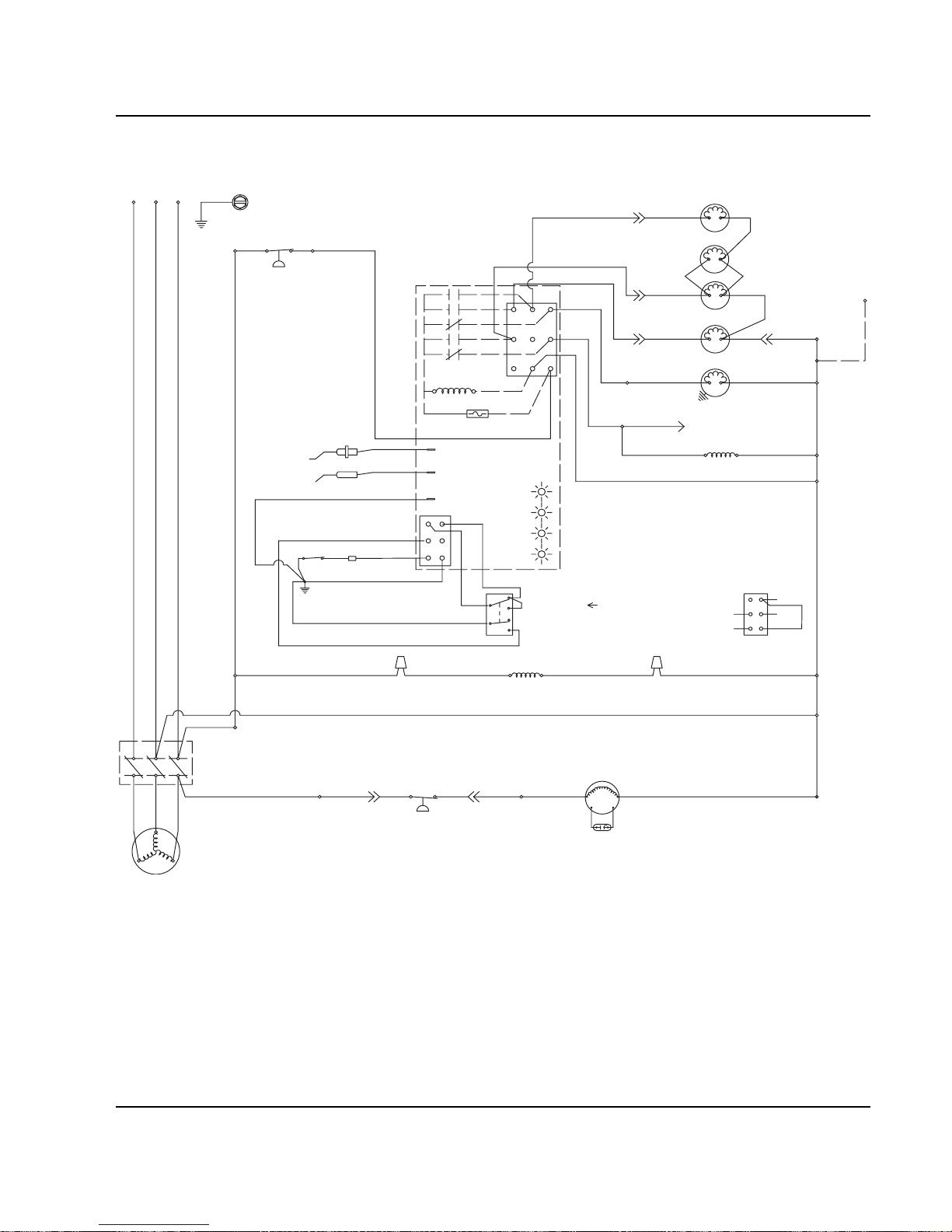
Section 6 Electrical System
Part No. 80-1100-3 6-27
Q1300/Q1800 - SELF CONTAINED - 3 PHASE WITH TERMINAL BOARD
TB31
TB37
(77)
(76)
(98)
(74)
(59)
(73)
(99)
(85)
(86)
(75)
LH HARVEST
SOLENOID
DUMP
SOLENOID
(81)
(80)
WATER
PUMP
TB30
TB30
TB30
CONTACTOR
COIL
TB30
TB30
FAN CYCLE CONTROL
FAN MOTOR
(AIR COOLED ONLY)
RUN CAPACITOR**
SEE SERIAL PLATE FOR VOLTAGE
CAUTION: DISCONNECT POWER BEFORE WORKING
ON ELECTRICAL CIRCUITRY.
DIAGRAM SHOWN DURING FREEZE CYCLE
TERMINATES AT
PIN CONNECTION
(61)
(60)
(57)
(58)
1F
1C
4
1
3
5
FUSE (7A)
TRANS.
(56)
ICE THICKNESS PROBE
TB30
BIN SWITCH LIGHT
HARVEST LIGHT/
SAFETY LIMIT CODE LIGHT
TB32
TB35
TB34
(53)
TB33
(52)
HIGH PRES
CUTOUT
TB35
CRANKCASE HEATER
(94)
(95)
L1
(96)
(42)
COMPRESSOR
L3 L2 L1
L2
L
3
TB35
T2
T3
T1
(55)
LOW D.C.
VOLTAGE
PLUG
(64)
(63)
BIN SWITCH
(62)
(66)
(65)
(69)
(67)
(68)
TOGGLE SWITCH
68
67
69
66
62
ICE
OFF
CLEAN
(66)
(62)
VIEW FOR WIRING
INTERNAL WORKING
VIEW
N - 50H
Z
ONLY
TB30
NOTE: WIRE (96) IS NOT USED ON 50HZ
TB30
CLEAN LIGHT
WATER LEVEL LIGHT
2
WATER
VALVE
(21)
(22)
(87)
(88)
RH HARVEST
SOLENOID
1G
AUCS DISPENSE TIME
WATER LEVEL PROBE
(20)
SV1653
Page 84
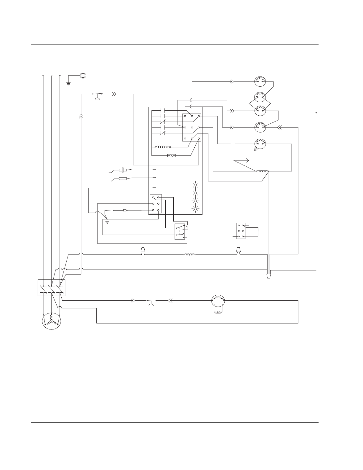
Electrical System Section 6
6-28 Part No. 80-1100-3
Q1300/Q1600/Q1800 - SELF CONTAINED - 3 PHASE WITHOUT TERMINAL BOARD
(77)
(76)
(98) (99)
(85)
(86)
(75)
LH HARVEST
SOLENOID
DUMP
SOLENOID
(81)
(80)
WATER
PUMP
CONTACTOR
COIL
FAN CYCLE CONTROL
FAN MOTOR
(AIR COOLED ONLY)
RUN CAPACITOR**
SEE SERIAL PLATE FOR VOLTAGE
CAUTION: DISCONNECT POWER BEFORE WORKING
ON ELECTRICAL CIRCUITRY.
DIAGRAM SHOWN DURING FREEZE CYCLE
TERMINATES AT
PIN CONNECTION
(61)
(60)
(57)
(59)
(58)
1F
1C
4
2
1
5
FUSE (7A)
TRANS.
(56)
ICE THICKNESS PROBE
BIN SWITCH LIGHT
HARVEST LIGHT/
SAFETY LIMIT CODE LIGHT
(51)
HIGH PRES
CUTOUT
CRANKCASE HEATER
(94)
(95)
CONTACTOR
CONTACTS
L1
(96)
COMPRESSOR
L3 L2 L1
L2L3
T2
T3
T1
LOW D.C.
VOLTAGE
PLUG
(64)
(88)
(89) (55)
(42)
(63)
BIN SWITCH
(62)
(65)
(69)
(67)
(68)
TOGGLE SWITCH
68
67
69
66
62
ICE
OFF
CLEAN
(66)
(62)
VIEW FOR WIRING
N - 50H
Z
ONLY
NOTE: WIRE (96) IS NOT USED ON 50HZ
CLEAN LIGHT
WATER LEVEL LIGHT
3
WATER
VALVE
(21)(20)
(22)
(87)
RH HARVEST
SOLENOID
1G
AUCS DISPENSE TIME
WATER LEVEL PROBE
(88)
SV3008
Page 85
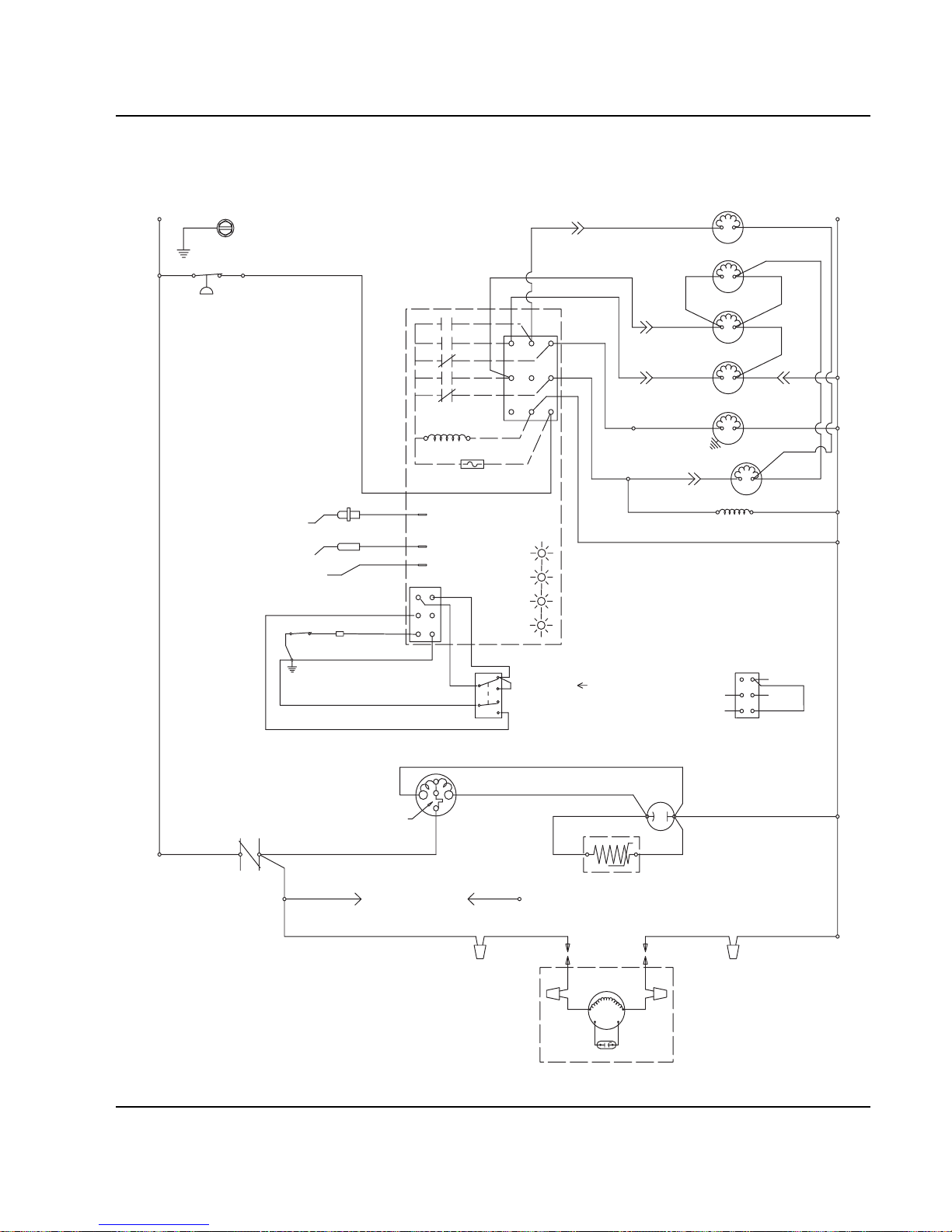
Section 6 Electrical System
Part No. 80-1100-3 6-29
Q450/Q600/Q800/Q1000 - REMOTE - 1 PHASE WITH TERMINAL BOARD
TB31
TB37
TB32
TB35
L1
(55)
(77)
(76)
(98)
(59)
(99)
(75)
HPR
SOLENOID
(79)(78)
HARVEST
SOLENOID
DUMP
SOLENOID
(81)
(80)
WATER
PUMP
LIQUID LINE
SOLENOID
TB3
0
TB3
0
(82)
(83)
HIGH PRES
CUTOUT
REMOTE
FAN MOTOR
RUN CAPACITOR
L2 (N)
SEE SERIAL PLATE FOR VOLTAGE
CAUTION: DISCONNECT POWER BEFORE WORKING
ON ELECTRICAL CIRCUITRY.
DIAGRAM SHOWN DURING FREEZE CYCLE
REMOTE CONDENSER
TERMINATES AT
PIN CONNECTION
(F1)
(F2)
(61)
(60)
(57)
(58)
1F
1C
4
1
3
FUSE (7A)
TRANS.
(56)
ICE THICKNESS PROBE
TB3
0
BIN SWITCH LIGHT
HARVEST LIGHT/
SAFETY LIMIT CODE LIGHT
(74)
(73)
TB3
0
CONTACTOR
COIL
R
R
C
S
R
TB34
*OVERLOAD
(53)
TB33
(52)
(51)
(48) (45)
(46)
(50)
(49)
(47)
T
B35
CONTACTOR
CONTACTS
L1
(42)
COMPRESSOR
RUN CAPACITOR
PTCR
TB3
0
TB3
0
LOW D.C.
VOLTAGE
PLUG
(64)
(63)
BIN SWITCH
(62)
(66)
(65)
(69)
(67)
(68)
TOGGLE SWITCH
68
67
69
66
62
ICE
OFF
CLEAN
(66)
(62)
VIEW FOR WIRING
INTERNAL WORKING
VIEW
CLEAN LIGHT
WATER LEVEL LIGHT
WATER LEVEL PROBE
(22)(21)
WATER
VALVE
2
5
1G
NOT USED
(20)
SV1648
Page 86
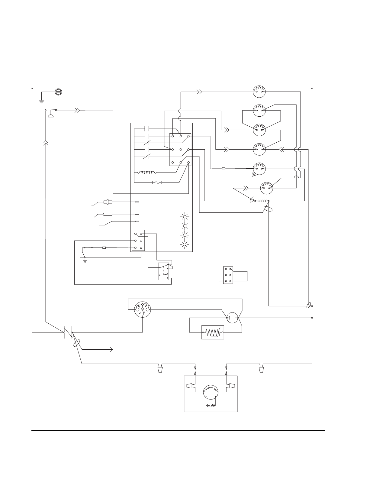
Electrical System Section 6
6-30 Part No. 80-1100-3
Q450/Q600/Q800/Q1000 - REMOTE - 1 PHASE WITHOUT TERMINAL BOARD
C
SR
L
1
*OVERLOAD
(51)
(48)
(42)
(45)
(46)
(49)
(47)
RR
(50)
(94)
(55)
(61)
(20) (21)
(77)
(60)
(98)
(57)
(74)
(58)
(59) (83) (82)
(99)
1F
1C
4
1
3
5
FUSE (7A)
TRANS.
(56)
ICE THICKNESS PROBE
(75)
HARVEST
SOLENOID
HPR
SOLENOID
DUMP
SOLENOID
(81)
(22)
WATER
PUMP
CONTACTOR
COIL
HIGH PRES
CUTOUT
BIN SWITCH LIGHT
HARVEST LIGHT/
SAFETY LIMIT CODE LIGHT
LOW D.C.
VOLTAGE
PLUG
CONTACTOR
CONTACTS
L1
COMPRESSOR
RUN CAPACITOR
LIQUID LINE
SOLENOID
REMOTE
FAN MOTOR
REMOTE CONDENSER
RUN CAPACITOR**
L2 (
N)
SEE SERIAL PLATE FOR VOLTAGE
CAUTION: DISCONNECT POWER BEFORE WORKING
ON ELECTRICAL CIRCUITRY.
DIAGRAM SHOWN DURING FREEZE CYCLE
PTCR
F1 F2
(64)
(63)
BIN SWITCH
(62)
(66)
(65)
(69)
(67)
(68)
TOGGLE SWITCH
68
67
69
66
62
ICE
OFF
CLEAN
(62)
VIEW FOR WIRING
CLEAN LIGHT
WATER LEVEL LIGHT
WATER LEVEL PROBE
AUCS DISPENSE TIME
(88) (80)
(78) (79)
WATER
VALVE
2
1G
(89)
(88)
SV2073
Page 87
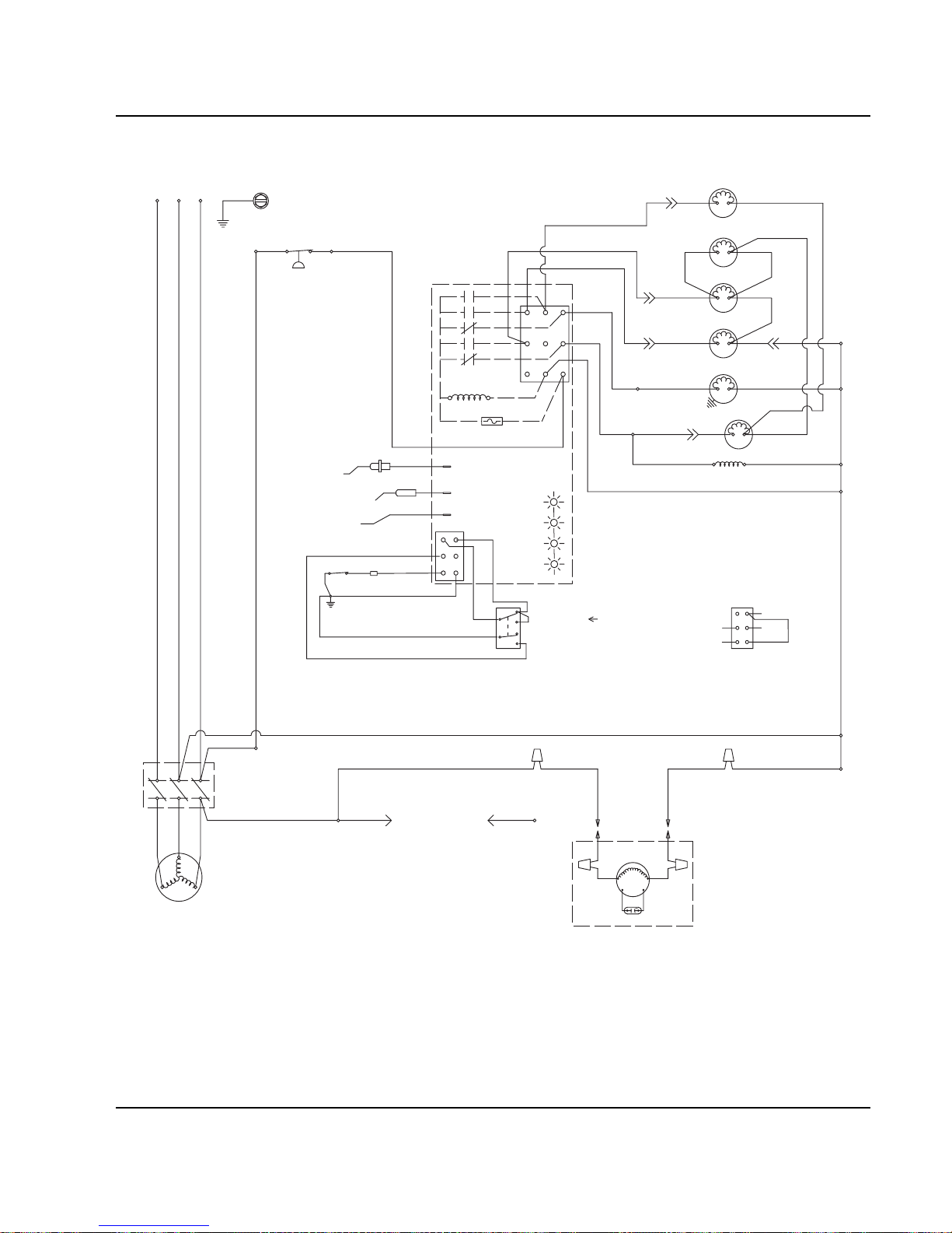
Section 6 Electrical System
Part No. 80-1100-3 6-31
Q800/Q1000 -REMOTE - 3 PHASE WITH TERMINAL BOARD
TB31
TB37
TB32
TB35
TB34
(53)
TB33
(52)
(55)
(77)
(76)
(98)
(59)
(99)
(75)
HPR
SOLENOID
(79)
(78)
HARVEST
SOLENOID
DUMP
SOLENOID
(81)
(80)
WATER
PUMP
LIQUID LINE
SOLENOID
TB3
0
TB3
0
(82)
(83)
HIGH PRES
CUTOUT
TB3
0
TB3
0
CONTACTOR
CONTACTS
L1
(96)
(42)
COMPRESSOR
REMOTE
FAN MOTOR
RUN CAPACITOR
S
EE SERIAL PLATE FOR VOLTAGE
CAUTION: DISCONNECT POWER BEFORE WORKING
ON ELECTRICAL CIRCUITRY.
DIAGRAM SHOWN DURING FREEZE CYCLE
REMOTE CONDENSER
L3 L2 L1
L2
L3
TB35
T2
T3
T1
TERMINATES AT
PIN CONNECTION
(F1)
(F2)
(61)
(60)
(57)
(58)
1F
1C
4
1
3
5
FUSE (7A)
TRANS.
(56)
ICE THICKNESS PROBE
TB3
0
BIN SWITCH LIGHT
HARVEST LIGHT/
SAFETY LIMIT CODE LIGHT
LOW D.C.
VOLTAGE
PLUG
(74)
(73)
TB3
0
CONTACTOR
COIL
(64)
(63)
BIN SWITCH
(62)
(66)
(65)
(69)
(67)
(68)
TOGGLE SWITCH
68
67
69
66
62
ICE
OFF
CLEAN
(62)
VIEW FOR WIRING
INTERNAL WORKING
VIEW
CLEAN LIGHT
WATER LEVEL LIGHT
WATER LEVEL PROBE
2
(22)
(21)
WATER
VALVE
1G
AUCS DISPENSE TIME
(20)
SV1649
Page 88

Electrical System Section 6
6-32 Part No. 80-1100-3
Q800/Q1000 -REMOTE - 3 PHASE WITHOUT TERMINAL BOARD
(55)
(89)
(88)
(42)
(51)
(85)
(77)
(76)
(98)
(59)
(99)
(75)
HPR
SOLENOID
(79)
(78)
HARVEST
SOLENOID
DUMP
SOLENOID
(81)
(80)
WATER
PUMP
LIQUID LINE
SOLENOID
(82)
(74)
(83)
HIGH PRES
CUTOUT
CONTACTOR
CONTACTS
L1
COMPRESSOR
REMOTE
FAN MOTOR
RUN CAPACITOR
SEE SERIAL PLATE FOR VOLTAGE
CAUTION: DISCONNECT POWER BEFORE WORKING
ON ELECTRICAL CIRCUITRY.
DIAGRAM SHOWN DURING FREEZE CYCLE
REMOTE CONDENSER
L3 L2 L1
L2
L3
T2
T3
T1
(F1)
(F2)
(61)
(20)
(60)
(57)
(58)
1F
1C
4
2
1
5
FUSE (7A)
TRANS.
(56)
ICE THICKNESS PROBE
BIN SWITCH LIGHT
HARVEST LIGHT/
SAFETY LIMIT CODE LIGHT
LOW D.C.
VOLTAGE
PLUG
CONTACTOR
COIL
(64)
(63)
BIN SWITCH
(62)
(66)
(65)
(69)
(67)
(68)
TOGGLE SWITCH
68
67
69
66
62
ICE
OFF
CLEAN
(62)
VIEW FOR WIRING
INTERNAL WORKING
VIEW
CLEAN LIGHT
WATER LEVEL LIGHT
WATER LEVEL PROBE
3
(22)
(21)
WATER
VALVE
1G
NOT USED
SV2074
Page 89

Section 6 Electrical System
Part No. 80-1100-3 6-33
Q1300/Q1800 - REMOTE - 1 PHASE WITH TERMINAL BOARD
TB31
TB37
TB32
T
B35
L1
TB34
(53)
TB33
(52)
(51)
(55)
(77)
(76)
(98)
(59)
(99)
(75)
WATER
VALVE
(22)
(21)
LH HARVEST
SOLENOID
DUMP
SOLENOID
(81)
(80)
WATER
PUMP
LIQUID LINE
SOLENOID
TB3
0
TB3
0
(82)
(83)
HIGH PRES
CUTOUT
TB35
CONTACTOR
CONTACTS
L1
(42)
REMOTE
FAN MOTOR
RUN CAPACITOR
L2 (N)
SEE SERIAL PLATE FOR VOLTAGE
CAUTION: DISCONNECT POWER BEFORE WORKING
ON ELECTRICAL CIRCUITRY.
DIAGRAM SHOWN DURING FREEZE CYCLE
REMOTE CONDENSER
TERMINATES AT
PIN CONNECTION
(F1)
(F2)
(61)
(60)
(57)
(58)
1F
1C
4
1
3
5
FUSE (7A)
TRANS.
(56)
ICE THICKNESS PROBE
TB3
0
BIN SWITCH LIGHT
HARVEST LIGHT/
SAFETY LIMIT CODE LIGHT
LOW D.C.
VOLTAGE
PLUG
R
R
C
S
R
*OVERLOAD
(48)
(45)
(46)
(50)
(49)
(47)
(74)
(73)
TB3
0
CONTACTOR
COIL
TB35
TB3
0
CRANKCASE HEATER
(94)(95)
TB3
0
CONTACTOR
CONTACTS
L2
(96)
COMPRESSOR
RUN CAPACITOR
PTCR
(44)
(64)
(63)
BIN SWITCH
(62)
(66)
(65)
(69)
(67)
(68)
TOGGLE SWITCH
68
67
69
66
62
ICE
OFF
CLEAN
(66)
(62)
VIEW FOR WIRING
INTERNAL WORKING
VIEW
HPR
SOLENOID
(87)(88)
CLEAN LIGHT
WATER LEVEL LIGHT
WATER LEVEL PROBE
2
(79)(78)
RH HARVEST
SOLENOID
1G
AUCS DISPENSE TIME
(20)
SV1650
Page 90

Electrical System Section 6
6-34 Part No. 80-1100-3
Q1300/Q1600/Q1800 - REMOTE - 1 Phase Without Terminal Board
TB37
RS
C
(48)
(51)
(55)(89)
(88)
(42)
(77)
(76)
(98)
(59)
(99)
(75)
RH HARVEST
SOLENOID
(87)
(88)
HPR
SOLENOID
(79)
(78)
LH HARVEST
SOLENOID
DUMP
SOLENOID
(81)
(80)
WATER
PUMP
LIQUID LINE
SOLENOID
(82)
(83)
HIGH PRES
CUTOUT
L2
CONTACTOR
CONTACTS
CONTACTOR
RUN CAPACITOR
RR
CONTACTS
L1
(49)
(96)
(74)
(94)
(47)
(45)
(46) (50)
(44)
PTCR
(95)
COMPRESSOR
CRANKCASE HEATER
*OVERLOAD
REMOTE
FAN MOTOR
RUN CAPACITOR
SEE SERIAL PLATE FOR VOLTAGECAUTION: DISCONNECT POWER BEFORE WORKING
ON ELECTRICAL CIRCUITRY.
DIAGRAM SHOWN DURING FREEZE CYCLE
REMOTE CONDENSER
L
1
L2 (N)
(F1) (F2)
(F2)
(61)
(60)
(57)
(58)
1F
1C
4
1
3
5
FUSE (7A)
TRANS.
(56)
ICE THICKNESS PROBE
BIN SWITCH LIGHT
HARVEST LIGHT/
SAFETY LIMIT CODE LIGHT
LOW D.C.
VOLTAGE
PLUG
CONTACTOR
COIL
(64)
(63)
BIN SWITCH
(62)
(66)
(65)
(69)
(67)
(68)
TOGGLE SWITCH
68
67
69
66
62
ICE
OFF
CLEAN
(62)
VIEW FOR WIRING
INTERNAL WORKING
VIEW
CLEAN LIGHT
WATER LEVEL LIGHT
WATER LEVEL PROBE
2
(22)
(21)(20)
WATER
VALVE
1G
AUCS DISPENSE TIME
SV2076
Page 91

Section 6 Electrical System
Part No. 80-1100-3 6-35
Q1300/Q1800 - REMOTE - 3 PHASE WITH TERMINAL BOARD
(64)
(63)
BIN SWITCH
(62)
(66)
(65)
(69)
(67)
(68)
TOGGLE SWITCH
68
67
69
66
62
ICE
OFF
CLEAN
(66)
(62)
VIEW FOR WIRING
INTERNAL WORKING
VIEW
TB31
TB37
TB32
TB35
TB34
(53)
TB33 (52)(51)
(55)
(77)
(76)
(98)
(59)
(99)
(75)
WATER
VALVE
(22)
(21)
LH HARVEST
SOLENOID
DUMP
SOLENOID
(81)
(80)
WATER
PUMP
LIQUID LINE
SOLENOID
TB30
TB30
(82)
(83)
HIGH PRES
CUTOUT
TB35
TB30
CRANKCASE HEATER
(94)
TB30
CONTACTOR
CONTACTS
L1
(96)
(42)
COMPRESSOR
REMOTE
FAN MOTOR
RUN CAPACITOR
SEE SERIAL PLATE FOR VOLTAGE
CAUTION: DISCONNECT POWER BEFORE WORKING
ON ELECTRICAL CIRCUITRY.
DIAGRAM SHOWN DURING FREEZE CYCLE
REMOTE CONDENSER
L3 L2 L1
L2L3
TB35
T2
T3
T1
TERMINATES AT
PIN CONNECTION
(F1)
(F2)
(61)
(60)
(57)
(58)
1F
1C
4
1
3
5
FUSE (7A)
TRANS.
(56)
ICE THICKNESS PROBE
TB30
BIN SWITCH LIGHT
HARVEST LIGHT/
SAFETY LIMIT CODE LIGHT
LOW D.C.
VOLTAGE
PLUG
(74)
(73)
TB30
CONTACTOR
COIL
(95)
N - 50H
Z
ONLY
NOTE: WIRE (96) IS NOT USED ON 50HZ
TB30
HPR
SOLENOID
(87)
(88)
CLEAN LIGHT
WATER LEVEL LIGHT
WATER LEVEL PROBE
2
(79)
(78)
RH HARVEST
SOLENOID
1G
AUCS DISPENSE TIME
(20)
SV1651
Page 92
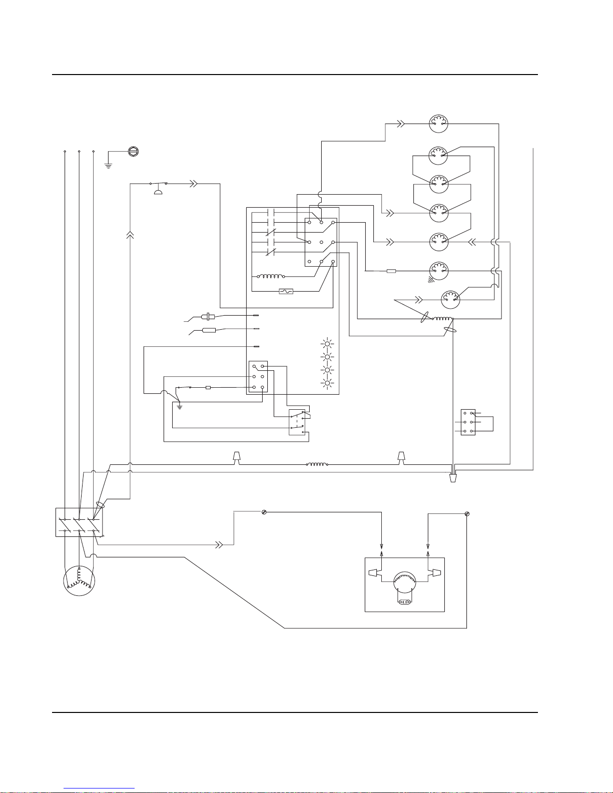
Electrical System Section 6
6-36 Part No. 80-1100-3
Q1300/Q1600/Q1800 - REMOTE - 3 PHASE WITHOUT TERMINAL BOARD
(55)(89)
(88)
(42)
(51)
(95) (94)
(96) (96)
NOTE: WIRE (96) IS NOT USED ON 50HZ
(77)
(76)
(98)
(59)
(99)
(75)
HPR
SOLENOID
(87)
(88)
(79)
(78)
RH HARVEST
SOLENOID
DUMP
SOLENOID
(81)
(80)
WATER
PUMP
LIQUID LINE
SOLENOID
(82)(83)
HIGH PRES
CUTOUT
CONTACTOR
CONTACTS
L1
COMPRESSOR
REMOTE
FAN MOTOR
RUN CAPACITOR
SEE SERIAL PLATE FOR VOLTAGE
CAUTION: DISCONNECT POWER BEFORE WORKING
ON ELECTRICAL CIRCUITRY.
DIAGRAM SHOWN DURING FREEZE CYCLE
REMOTE CONDENSER
L3 L2 L1
L2
L3
T2
T3
T1
(F1)
(F2)
(61)
(20)
(60)
(57)
(58)
1F
1C
4
2
1
5
FUSE (7A)
TRANS.
(56)
(74)
ICE THICKNESS PROBE
BIN SWITCH LIGHT
HARVEST LIGHT/
SAFETY LIMIT CODE LIGHT
LOW D.C.
VOLTAGE
PLUG
CONTACTOR
COIL
(64)
(63)
BIN SWITCH
(62)
(66)
(65)
(69)
(67)
(68)
TOGGLE SWITCH
68
67
69
66
62
ICE
OFF
CLEAN
(62)
VIEW FOR WIRING
INTERNAL WORKING
VIEW
CLEAN LIGHT
WATER LEVEL LIGHT
WATER LEVEL PROBE
3
(22)
(21)
WATER
N - 50 H
Z
ONL
Y
VALVE
1G
NOT USED
LH HARVEST
SOLENOID
SV2077
Page 93

Section 6 Electrical System
Part No. 80-1100-3 6-37
THIS PAGE INTENTIONALLY LEFT BLANK
Page 94

Electrical System Section 6
6-38 Part No. 80-1100-3
Component Specifications and Diagnostics
MAIN FUSE
Function
The control board fuse stops ice machine operation if
electrical components fail causing high amp draw.
Specifications
The main fuse is 250 Volt, 7 amp.
Check Procedure
1. If the bin switch light is on with the water curtain
closed, the fuse is good.
2. Remove the fuse. Check the resistance across the
fuse with an ohm meter.
BIN SWITCH
Function
Movement of the water curtain controls bin switch
operation. The bin switch has two main functions:
1. Terminating the harvest cycle and returning the ice
machine to the freeze cycle.
This occurs when the bin switch is opened and
closed again within 7 seconds during the harvest
cycle.
2. Automatic ice machine shut-off.
If the storage bin is full at the end of a harvest cycle,
the sheet of cubes fails to clear the water curtain and
holds it open. After the water curtain is held open for
7 seconds, the ice machine shuts off. The ice
machine remains off until enough ice is removed
from the storage bin to allow the sheet of cubes to
drop clear of the water curtain. As the water curtain
swings back to the operating position, the bin switch
closes and the ice machine restarts, provide the
three-minute delay has expired.
Specifications
The bin switch is a magnetically operated reed switch.
The magnet is attached to the lower right corner of the
water curtain. The switch is attached to the evaporatormounting bracket.
The bin switch is connected to a varying D.C. voltage
circuit. (Voltage does not remain constant.)
NOTE: Because of a wide variation in D.C. voltage, it is
not recommended that a voltmeter be used to chec k bin
switch operation.
!
Warning
High (line) voltage is applied to the control board
(terminals #55 and #56) at all times. Removing the
control board fuse or moving the toggle switch to
OFF will not remove the power supplied to the
control board.
!
Warning
Disconnect electrical power to the entire ice
machine before proceeding.
Reading Result
Open (OL) Replace fuse
Closed (O) Fuse is good
Important
The water curtain must be ON (bin switch(s) closed)
to start ice making.
Page 95

Section 6 Electrical System
Part No. 80-1100-3 6-39
Check Procedure
1. Set the toggle switch to OFF.
2. Watch the bin switch light on the control board.
3. Move the water curtain toward the evaporator. The
bin switch must close. The bin switch light “on”
indicates the bin switch has closed properly.
Move the water curtain away from the evaporator. The
bin switch must open. The bin switch light “off” indicates
the bin switch has opened properly.
OHM Test
1. Disconnect the bin switch wires to isolate the bin
switch from the control board.
2. Connect an ohmmeter to the disconnected bin
switch wires.
3. Cycle the bin switch open and closed numerous
times by opening and closing the water curtain.
NOTE: To prevent misdiagnosis:
• Always use the water curtain magnet to cycle the
switch (a larger or smaller magnet will affect switch
operation).
• Watch for consistent readings when the bin switch is
cycled open and closed (bin switch failure could be
erratic).
Water Curtain Removal Notes
The water curtain must be on (bin switch closed) to start
ice making. While a freeze cycle is in progress, the water
curtain can be removed and installed at any time without
interfering with the electrical control sequence.
If the ice machine goes into harvest sequence while the
water curtain is removed, one of the following will
happen:
• Water curtain re mains off:
When the harvest cycle time reaches 3.5 minutes
and the bin switch is not closed, the ice machine
stops as though the bin were full.
• Water curtain is put back on:
If the bin switch closes prior to reaching the 3.5minute point, the ice machine immediately returns to
another freeze sequence prechill.
Page 96

Electrical System Section 6
6-40 Part No. 80-1100-3
COMPRESSOR ELECTRICAL DIAGNOSTICS
The compressor will not start or will trip repeatedly on
overload.
Check Resistance (Ohm) Values
NOTE: Compressor windings can have very low ohm
values. Use a properly calibrated meter.
Perform the resistance test after the compressor cools.
The compressor dome should be cool enough to touch
(below 120°F/49°C) to assure that the overload is clo sed
and the resistance readings will be accurate.
SINGLE PHASE COMPRESSORS
1. Disconnect power from the cuber and remove the
wires from the compressor terminals.
2. The resistance values must be within published
guidelines for the compressor. The resistance
values between C and S and between C and R,
when added together, sh ould equal the resistance
value between S and R.
3. If the overload is open, there will be a resistance
reading between S and R, and open readings
between C and S and between C and R. Allow the
compressor to cool, then check the readings again.
THREE PHASE COMPRESSORS
1. Disconnect power from the cuber and remove the
wires from the compressor terminals.
2. The resistance values must be within published
guidelines for the compressor. The resistance
values between L1 and L2, between L2 and L3, and
between L3 and L1 should all be equal.
3. If the overload is open, there will be open readings
between L1 and L2, between L2 and L3, and
between L3 and L1. Allow the compressor to cool,
then check the readings again.
Check Motor Windings to Ground
Check continuity between all three terminals and the
compressor shell or copper refrigeration line. Scrape
metal surface to get good contact. If continuity is
present, the compressor windings are grounded and the
compressor should be replaced.
Determine if the Compressor is Seized
Check the amp draw while the compressor is trying to
start.
COMPRESSOR DRAWING LOCKED ROTOR
The two likely causes of this are:
• Defective starting component
• Mechanically seized compressor
To determine which you have:
1. Install high and low side gauges.
2. Try to start the compressor.
3. Watch the pressures closely.
A. If the pressures do not move, the compressor is
seized. Replace the compressor.
B. If the pressures move, the compressor is turning
slowly and is not seized. Check the capacitors
and start relay.
COMPRESSOR DRAWING HIGH AMPS
The continuous amperage draw on start-up should not
be near the maximum fuse size indicated on the serial
tag.
The voltage when the compressor is trying to start must
be within ±10% of the nameplate voltage.
Diagnosing Capacitors
• If the compr essor atte mpt s to st art, or h ums and t rips
the overload protector, check the starting
components before replacing the compressor.
• Visual evidence of capacitor failure can include a
bulged terminal end or a ruptured membrane. Do not
assume a capacitor is good if no visual evidence is
present.
• A good test is to install a known good substitute
capacitor.
• Use a capacitor tester when checking a suspect
capacitor. Clip the bleed resistor off the capa citor
terminals before testing.
Page 97

Section 6 Electrical System
Part No. 80-1100-3 6-41
PTCR DIAGNOSTICS
What is a PTCR?
A PTCR (or Positive T emperature Coefficient Resistor) is
made from high-purity, semi-conducting ceramics.
A PTCR is useful because of its resistance versus
temperature characteristic. The PTCR has a low
resistance over a wide (low) temperature range, but
upon reaching a certain higher temperature, its
resistance greatly increases, virtually stopping current
flow. When the source of heat is removed, the PTCR
returns to its initial base resistance.
In severe duty cycles, it can be used to repeatedly
switch (virtually stop) large currents at line voltages.
PTCR’s have been used for many years in millions of
HVAC applications. In place of using the conventional
start relay/start capacitor, a simple PTCR provides the
starting torque assistance to PSC (Permanent Split
Capacitor) single-phase compressors, which can
equalize pressures before star ting.
Compressor Start Sequence
PTCR’s provide additional starting torque by increasing
the current in the auxiliary (start) winding during starting.
The PTCR is wired across the run capacitor (in series
with the start winding).
1. It is important for the refrigerant discharge and
suction pressures to be somewhat equalized prior to
the compressor starting. To assure equalization of
pressures the harvest valve (and HPR valve on
remotes) will energize for 45 seconds prior to
compressor starting. The harvest valve (and HPR
valve on remotes) remains on for an additional 5
seconds while the compressor is starting.
2. When starting the compressor, the contactor closes
and the PTCR, which is at a low resistance value,
allows high starting current to flow in the start
winding.
3. The current passing through the PTCR causes it to
rapidly heat up, and after approximately .25-1
second it abruptly “switches” to a very high
resistance, virtually stopping current flow through it.
4. At this point the motor is up to speed and all current
going through the start winding will now pass
through the run capacitor.
5. The PTCR remains hot and at a high resistance as
long as voltage remains on the circuit.
6. It is important to provide time between compressor
restarts to allow the PTCR to cool down to near its
initial temperature (low resistance). When the
contactor opens to stop the compressor, the PTCR
cools down to its initial low resistance and is again
ready to provide starting torque assistance. To
assure the PTCR has cooled down, during an
automatic shut-off, the Q model ice machines have a
built-in 3-minute off time before it can restart.
Page 98

Electrical System Section 6
6-42 Part No. 80-1100-3
Q-Model Automatic Shut-Off and Restart
When the storage bin is full at the end of a harvest cycle,
the sheet of cubes fails to clear the water curtain and will
hold it open. After the water curtain is held open for 7
seconds, the ice machine shuts of f. To assure the PTCR
has cooled, the ice machine remains off for 3 minutes
before it can automatically restart.
The ice machine remains off until enough ice has been
removed from the storage bin to allow the ice to fall clear
of the water curtain. As the water curtain swings back to
operating position, the bin switch closes and the ice
machine restarts, provided the three -minute delay period
is complete.
Figure 6-15. During Start-Up (First .25 - 1.0 Seconds)
Figure 6-16. After Start-Up
(Current Flows Through Run Capacitor)
Troubleshooting PTCR’s
WHY A GOOD PTCR MAY FAIL
TO START THE COMPRESSOR
The PTCR must be cooled before attempting to start the
compressor, other wise the high starting torque may not
last long enough.
For example, if the PTCR is properly cooled, say 60°F
(15.6°C) when the compressor starts, it will take .25 to
1.0 seconds before its temperature reaches 260°F
(126.6°C), and current flow is stopped.
If the PTCR is still warm, say 160°F (71.1°C) when the
compressor starts, it will take only .125 to .50 seconds
before its temperature reaches 260°F (126.6°C), and
current flow is stopped. This decreased time may be
insufficient to start the compressor.
A good PTCR may be too hot to operate properly at
start-up because:
• The ice machine’s 3-minute delay has been
overridden. Opening and closing the service
disconnect or cycling the toggle switch from OFF to
ICE will override the delay period.
• The control box temperature is too high. Though
rare, very high air temperatures (intense sunlight,
etc.) can greatly increase the temperature of the
control box and its contents. This may require a
longer off time to allow the PTCR to cool.
• The comp ressor has short-cycled, or th e compressor
overload has opened. Move the toggle switch to OFF
and allow the compressor and PTCR to cool.
Continued on next page …
SV1506
L1
L2
CONTACTOR
CONTACTS
RUN CAPACITOR
RR
PTCR
COMPRESSOR
C
S
R
SV1507
L1
L2
CONTACTOR
CONTACTS
RUN CAPACITOR
RR
PTCR
COMPRESSOR
C
S
R
Page 99

Section 6 Electrical System
Part No. 80-1100-3 6-43
There are other problems that may cause compressor
start-up failure with a good PTCR in a new, properly
wired ice machine.
• Th e voltage at the compressor during start-up is too
low.
Manitowoc ice machines are rated at ±10% of
nameplate voltage at compressor start-up. (Ex: An
ice machine rated at 208-230 should have a
compressor start-up voltage between 187 and 253
volts.)
• The compressor discharge and suction pressures
are not matched closely enough or equalized.
These two pressures must be somewhat equalized
before attempting to start the compressor. The
harvest valve (and HPR valve on remotes) energizes
for 45 seconds before the compressor starts, and
remains on 5 seconds after the compressor starts.
Make sure this is occurring and the harvest valve
(and HPR solenoid) coil is functional before
assuming that the PTCR is bad.
CHECKING THE PTCR
1. Visually inspect the PTCR. Check for signs of
physical damage.
NOTE: The PTCR case temperature may reach 21 0 °F
(100°C) while the compressor is running. This is normal.
Do not change a PTCR just because it is hot.
2. Wait at least 10 minutes for the PTCR to cool to
room temperature.
3. Remove the PTCR from the ice machine.
4. Measure the resistance of the PTCR as shown
below. If the resistance falls outside of the
acceptable range, replace it.
Figure 6-17. Manitowoc PTCR’s 8505003 & 8504993
Figure 6-18. Manitowoc PTCR 8504913
!
Warning
Disconnect electrical power to the entire ice
machine at the building electrical disconnect box
before proceeding.
Model
Manitowoc
Part Number
Cera-Mite
Part Number
Room
Temperature
Resistance
Q200
Q280
Q320
Q420
Q450
8505003 305C20 22-50 Ohms
Q600
Q800
Q1000
8504993 305C19 18-40 Ohms
Q1300
Q1600
Q1800
8504913 305C9 8-22 Ohms
SV1540
SV1541
Page 100

Electrical System Section 6
6-44 Part No. 80-1100-3
ICE/OFF/CLEAN TOGGLE SWITCH
Function
The switch is used to place the ice machine in ICE, OFF
or CLEAN mode of operation.
Specifications
Double-pole, double-throw switch. The switch is
connected into a varying low D.C. voltage circuit.
Check Procedure
NOTE: Because of a wide variation in D.C. voltage, it is
not recommended that a volt meter be used to check
toggle switch operation.
1. Inspect the toggle switch for correct wiring.
2. Isolate the toggle switch by disconnecting all wires
from the switch, or by disconnecting the Molex
connector and removing wire #69 from the toggle
switch.
3. Check across the toggle switch terminals using a
calibrated ohm meter . Note wher e the wire numbers
are connected to the switch terminals, or refer to the
wiring diagram to take proper readings.
4. Replace the toggle switch if ohm readings do not
match all three switch settings.
CONTROL BOARD RELAYS
Function
The control board relays energize and de -e n ergize
system components.
Specifications
Relays are not field replaceable. There are five relays on
the control board:
Switch Setting Terminals Ohm Reading
ICE
66-62 Open
67-68 Closed
67-69 Open
CLEAN
66-62 Closed
67-68 Open
67-69 Closed
OFF
66-62 Open
67-68 Open
67-69 Open
Relay Controls
#1 Water Pump
#2 Water Inlet Valve
#3 Harvest Valve / HPR Valve (Remotes)
#4 Water Dump Valve
#5 Contactor (Self-Contained)
Contactor / Liquid Line Solenoid (Remotes)
 Loading...