

Page 1
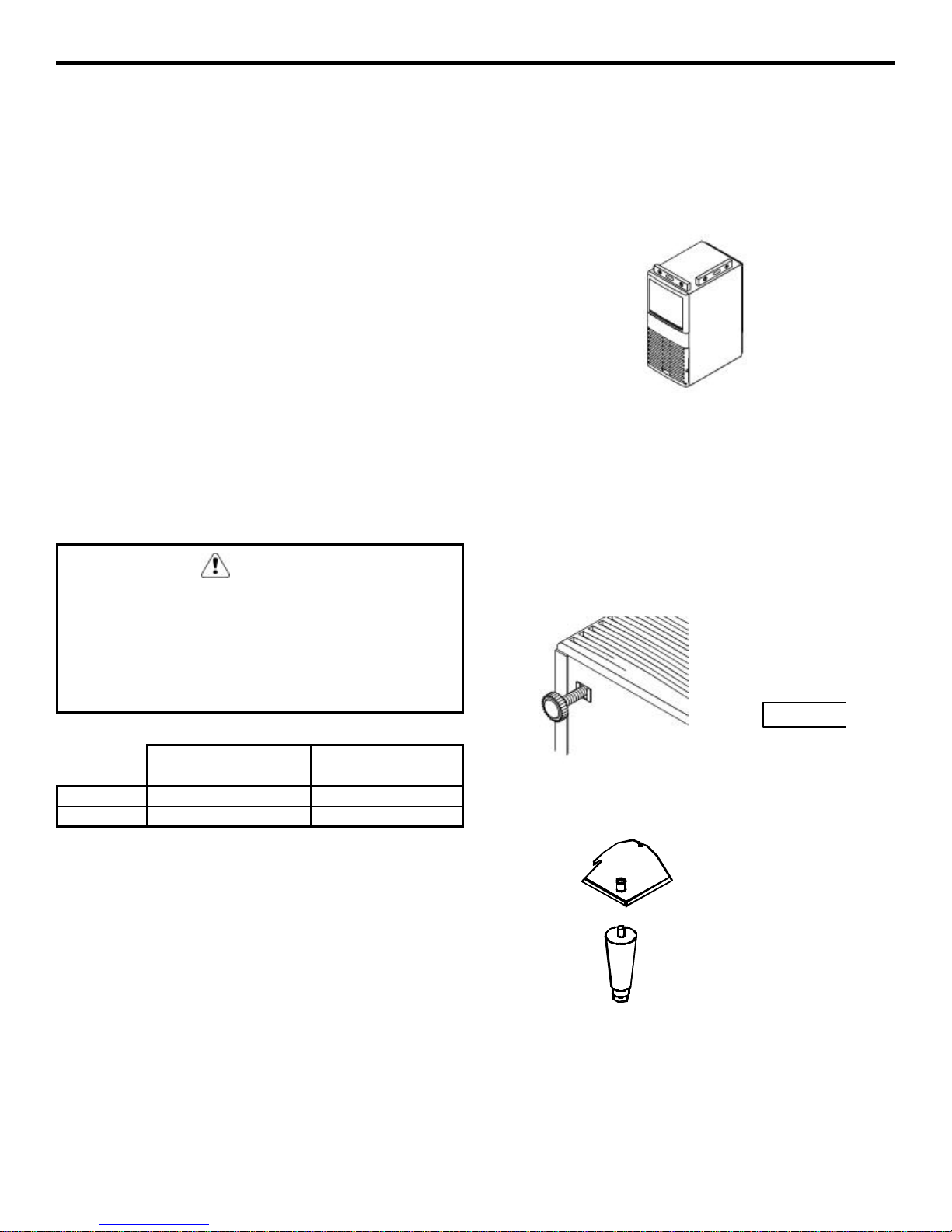
QM30 Series
Ice Machines
Installation,
Use and Care,
and Service Manual
Thank you for selecting a Manitowoc Ice Machine, the dependability leader in ice making equipment and related
products. With proper care and maintenance, your new Manitowoc Ice Machine will provide you with many
years of reliable and economical performance.
We reserve the right to make product improvements at any time.
Specifications and design are subject to change without notice.
Part Number 80-1121-3
Rev. C 01/01
Page 2
Safety Notices
Procedural Notices
When using or servicing these Ice Machines, be sure to
pay close attention to the safety notices in this manual.
Disregarding the notices may lead to serious injury and/or
damage to the ice machine.
Throughout this manual, you will see the following types
of safety notices:
WARNING
Text in a Warning box alerts you to a potential personal
injury situation. Be sure to read the Warning statement,
and then proceed carefully.
CAUTION
Text in a Caution box alerts you to a situation in which
you could damage the ice machine. Be sure to read the
Caution statement, and then proceed carefully.
When using or servicing these Ice Machines, be sure to
read the procedural notices in this manual. These notices
supply helpful and important information.
Throughout this manual, you will see the following types
of procedural notices:
Important
Important boxes serve two functions.
They call the operator’s attention to important
information.
They also provide the service technician with
information that may help perform a procedure more
efficiently. Disregarding this information may slow down
the work.
NOTE: Text set off as a Note provides you with simple,
but useful, extra information.
CAUTION
Proper care and maintenance are essential for
maximum ice production and trouble-free operation of
your Manitowoc Ice Machine.
Read and understand this manual. It contains valuable
care and maintenance information. If you encounter
problems not covered by this manual, feel free to
contact Manitowoc Ice, Inc. We will be happy to
provide assistance.
Warning
PERSONAL INJURY POTENTIAL
Do not operate equipment that has been,
misused, abused, neglected, damaged, or
altered/modified from that of original
manufactured specifications.
This manual covers the following model numbers:
Self-Contained Air-Cooled:
QM30A
QM30AE
Page 3

We reserve the right to make product
improvements at any time.
Specifications and design are subject
to change without notice.
MANITOWOC ICE, INC.
2110 South 26th Street P.O. Box 1720
Manitowoc, WI 54221-1720 USA
Phone: (920) 682-0161
Service Fax: (920) 683-7585
Web Site - www.manitowocice.com
ã2000 Manitowoc Ice, Inc.
Litho in U.S.A.
Page 4

Table of Contents
Table of Contents
Section 1 - General Information
Model/Serial Number Location.......................................................................................................................1-1
Owner Warranty Registration Card..............................................................................................................1-2
Warranty Coverage..........................................................................................................................................1-2
Section 2 - Installation Instructions
Dimensions........................................................................................................................................................2-1
Location of Ice Machine ..................................................................................................................................2-2
Leveling the Ice Machine.................................................................................................................................2-2
Electrical Service..............................................................................................................................................2-3
Water Service/Drains.......................................................................................................................................2-5
Section 3 - Ice Machine Operation
Sequence of Operation.....................................................................................................................................3-1
Ice Thickness Adjustment ...............................................................................................................................3-2
Section 4 - Maintenance
General..............................................................................................................................................................4-1
Ice Machine Inspection....................................................................................................................................4-1
Exterior Cleaning.............................................................................................................................................4-1
Cleaning the Condenser...................................................................................................................................4-2
Interior Cleaning and Sanitizing ....................................................................................................................4-3
Removal of Parts ..............................................................................................................................................4-5
Overview of Parts Removal.............................................................................................................................4-7
Removal from Service/Winterization.............................................................................................................4-8
Section 5 - Before Calling for Service
Checklist............................................................................................................................................................5-1
i
Page 5

Table of Contents
Section 6 - Service
Wiring Diagrams
230/50/1..................................................................................................................................................6-1
115/60/1..................................................................................................................................................6-2
Component Specifications and Diagnostics
Control Board Fuse/Relays .................................................................................................................6-3
Toggle Switch........................................................................................................................................6-3
Bin Thermostat.....................................................................................................................................6-4
Thermistor ............................................................................................................................................6-5
Compressor (Electrical Diagnostics Only)...........................................................................................6-6
Hot Gas Valve.......................................................................................................................................6-7
Ice Machine Will Not Run...............................................................................................................................6-8
Refrigeration Tubing Schematic.....................................................................................................................6-9
Cycle Times/24-Hour Production Charts/Ice Production Check................................................................6-10
Ice Production Check.......................................................................................................................................6-11
Refrigeration Diagnostics................................................................................................................................6-11
Refrigerant Recovery/Evacuation and Recharging......................................................................................6-12
Refrigerant Charging Procedure....................................................................................................................6-13
Refrigerant Charge..........................................................................................................................................6-13
ii
Page 6
Section 1 General Information
Section 1
General Information
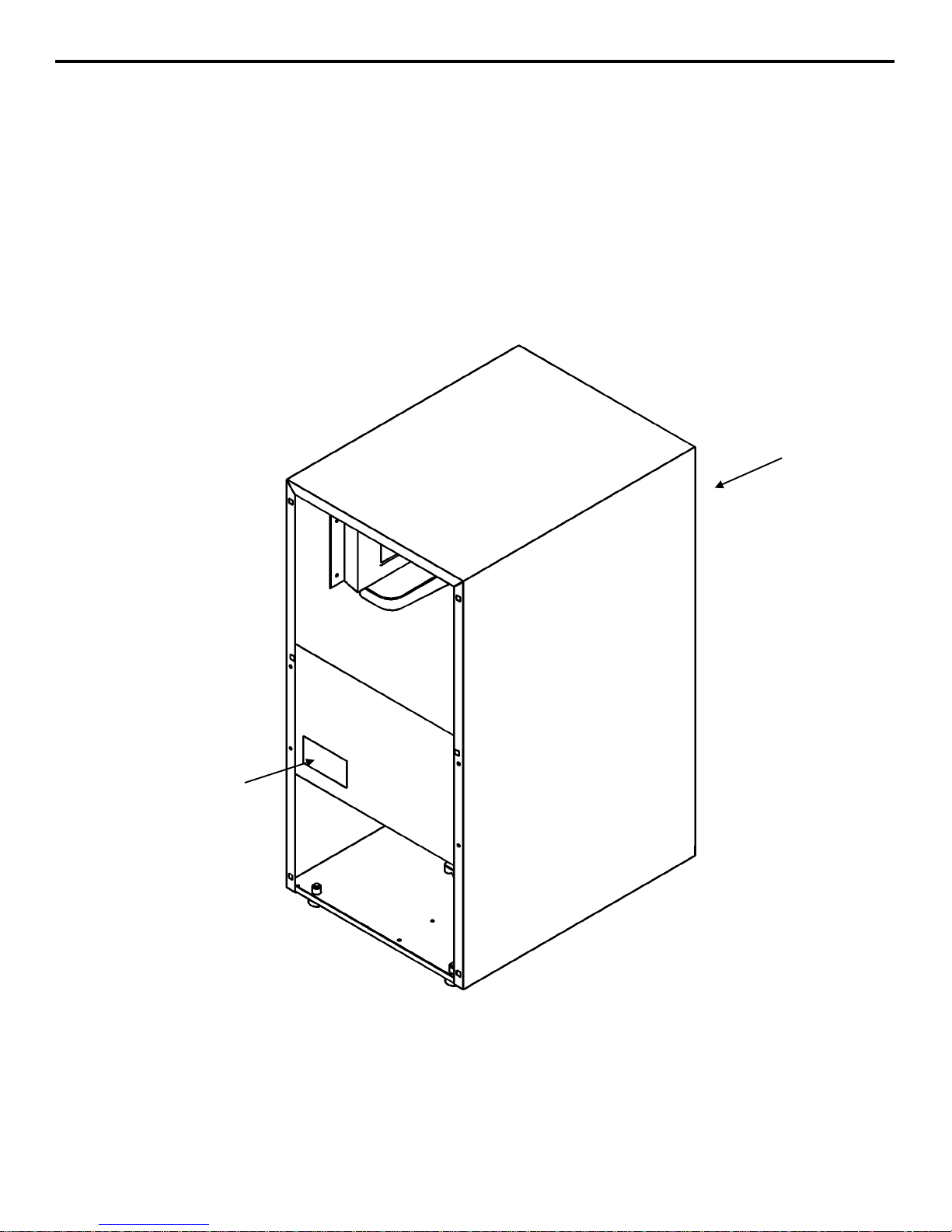
Model/Serial Number Location
Record the model and serial number of your ice
machine in the space provided below. These numbers
are required when requesting information from your
Manitowoc distributor, service representative, or the
factory.
The model and serial number are listed on the
OWNER WARRANTY REGISTRATION CARD.
They are also listed on the MODEL/SERIAL
NUMBER DECAL affixed to the ice machine.
MODEL AND
SERIAL NUMBER
MODEL AND
SERIAL NUMBER
MODEL NUMBER: ________________________ SERIAL NUMBER: _________________________
sv1702
Model/Serial Number Location
1-1
Page 7

General Information Section 1
Owner Warranty Registration Card
GENERAL
The packet containing this manual also includes
warranty information. Warranty coverage begins the
day your new ice machine is installed.
Important
Complete and mail the OWNER WARRANTY
REGISTRATION CARD as soon as possible to
validate the installation date.
If you do not return your OWNER WARRANTY
REGISTRATION CARD, Manitowoc will use the
date of sale to the Manitowoc Distributor as the first
day of warranty coverage for your new ice machine.
Warranty Coverage
GENERAL
The following Warranty outline is provided for your
convenience. For a detailed explanation, read the
warranty bond shipped with each product.
Contact your local Manitowoc representative or
Manitowoc Ice, Inc. if you need further warranty
information.
Important
This product is intended exclusively for
commercial application. No warranty is extended
for personal, family, or household purposes..
EXCLUSIONS
The following items are not included in the ice
machine’s warranty coverage:
1. Normal maintenance, adjustments and cleaning
as outlined in the Owner/Operator Use and Care
Guide.
2. Repairs due to unauthorized modifications to the
ice machine or the use of non-standard parts
without prior written approval Manitowoc Ice,
Inc.
3. Damage caused by improper installation of the
ice machine, electrical supply, water supply or
drainage, or damage caused by floods, storms,
or other acts of God.
4. Premium labor rates due to holidays, overtime,
etc.; travel time; flat rate service call charges;
mileage and miscellaneous tools and material
charges not listed on the payment schedule.
Additional labor charges resulting from the
inaccessibility of the ice machine are also
excluded.
5. Parts or assemblies subjected to misuse, abuse,
neglect or accidents.
6. Damage or problems caused by installation,
cleaning and/or maintenance procedures
inconsistent with the technical instructions
provided in the Installation Manual and the
Owner/Operator Use and Care Guide.
PARTS
Manitowoc warrants the ice machine against defects
in materials and workmanship, under normal use
and service for three (3) years from the date of
original installation.
LABOR
Labor required to repair or replace defective
components is covered for three (3) years from the
date of original installation.
1-2
AUTHORIZED WARRANTY SERVICE
To comply with the provisions of the warranty, a
refrigeration service company, qualified and
authorized by a Manitowoc distributor, or a
Contracted Service Representative must perform the
warranty repair.
NOTE: If the dealer the ice machine was purchased
from is not authorized to perform warranty service,
contact the Manitowoc distributor or Manitowoc
Ice, Inc. for the name of the nearest authorized
service representative.
Service Calls
If you have followed the procedures listed in
Section 5 of this manual, and the ice machine still
does not perform properly, call your authorized
service company.
Page 8
Section 2 Installation Instructions
n
t
(
)
(
)
Section 2
Installation Instructions
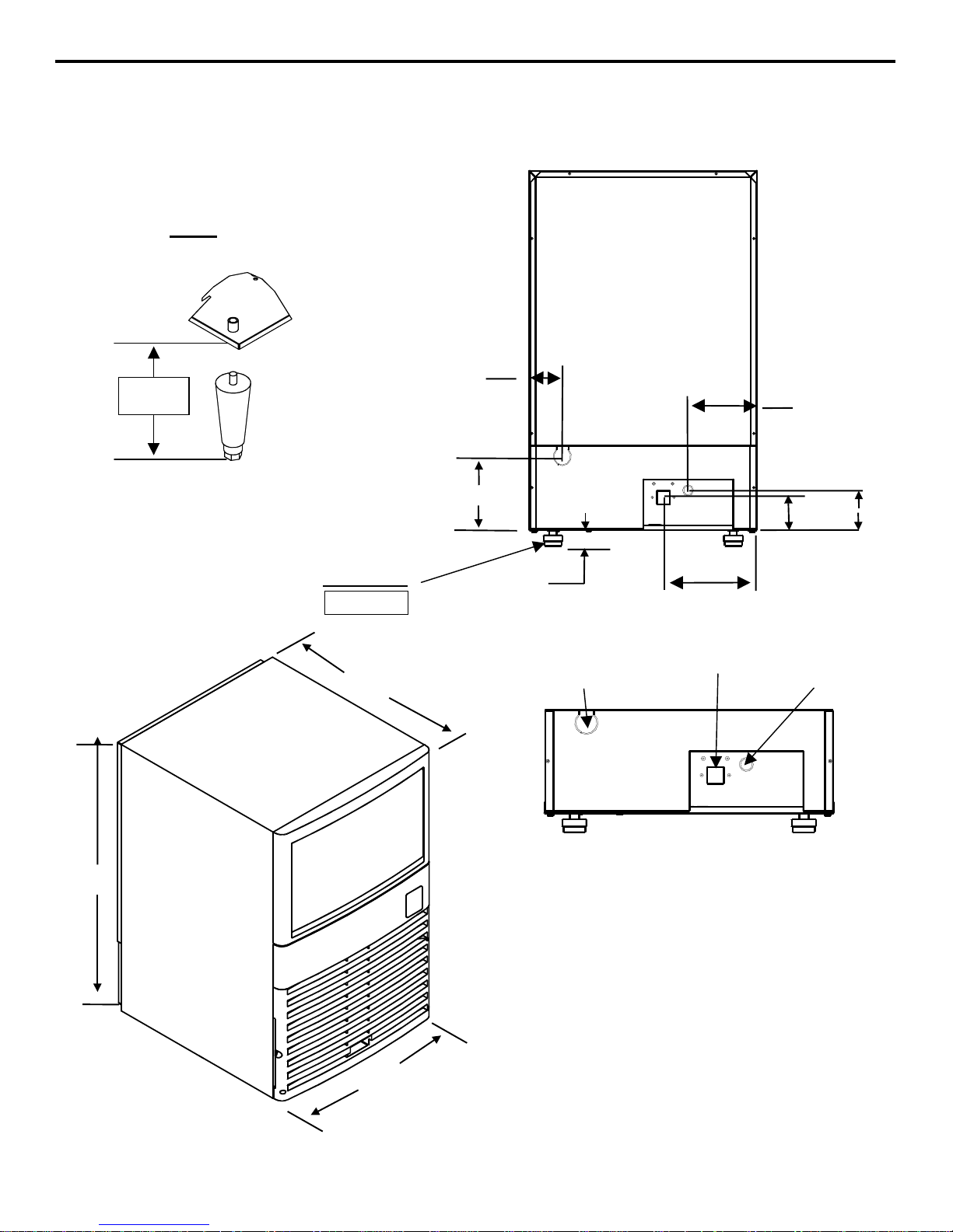
Legs
15.24 cm
(6.00”)
sv1679b
Levelers
International
ONLY
56.74 cm
(22.34”)
7.32 cm
(2.88”)
15.73 cm
6.19”
3.33 cm
(1.31”)
Ice Making
Water/Bin Drai
20.80 cm
(8.19”)
Ice Making
Water Inle
15.09 cm
(5.94”)
9.53 cm
(3.75”)
7.24 cm
(2.85”)
sv1678b
Electrical Inlet
sv1678c
8.51 cm
3.35”
76.20 cm
(30.00”)
50.00 cm
(19.69”)
2-1
Page 9
Installation Instructions Section 2
2-
2
International
Location of Ice Machine
The location selected for the ice machine must meet
the following criteria. If any of these criteria are not
met, select another location.
• The location must be indoors.
• The location must be free of airborne and other
contaminants.
• The air temperature must be at least 10°C (50°F),
but must not exceed 45°C (113°F).
• The location must not be near heat-generating
equipment or in direct sunlight.
• The counter top (or other resting surface) must be
able to support 425 kg per square meter (0.6 lb.
per square inch).
• The location must allow enough clearance for
water, drain, and electrical connections in the
rear of the ice machine.
• The location must not obstruct air flow to any
portion of the front of the ice machine.
CAUTION
The ice machine must be protected if it will be
subjected to temperatures below 0°C (32°F).
Failure caused by exposure to freezing
temperatures is not covered by the warranty. See
“Removal from Service/Winterization” on page 4-
8.
Leveling the Ice Machine
After moving the ice machine into the installation
location, it must be leveled for proper operation.
Follow these steps to level the ice machine:
1. Use a level to check the levelness of the ice
machine from front to back and from side to side.
sv1704
Checking the Levelness
2. If the ice machine is not level, adjust the leveling
glides or legs on each corner of the base of the ice
machine as necessary.
3. Check the levelness of the ice machine after each
adjustment.
4. Repeat steps 2 and 3 until the ice machine is level
from front to back and from side to side.
Levelers
ONLY
Self-Contained
Air-Cooled
Top/Sides 5” (203 mm)* 5” (127 mm)*
Back 5” (127 mm)* 5” (127 mm)*
Self-Contained
Water-Cooled
NOTE: The ice machine may be built into a cabinet.
There is no minimum clearance requirement for the
top or the left and right sides of the ice machine
sv1705
Legs
sv1679b
Page 10
Section 2 Installation Instructions
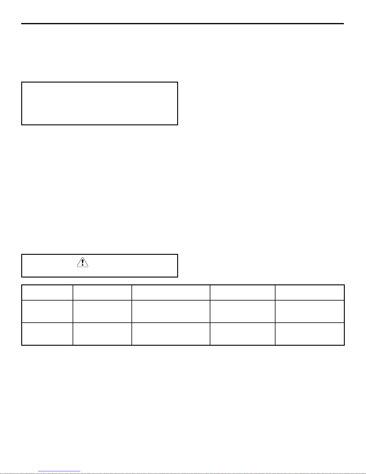
Electrical Service
WARNING
All wiring must conform to local, state and national
codes.
Ice Machine Voltage Phase Air-Cooled
Model Cycle Electrical Rating
QM30 230/50/1 .6 KW / 2.6 Amps
QM30 115/60/1 .6 KW/ 5.3 Amps
VOLTAGE
The maximum allowable voltage variation is ± 10%
of the rated voltage at ice machine start-up (when the
electrical load is highest).
WARNING
The ice machine must be grounded in accordance
with national and local electrical codes.
WARNING
Never use an extension cord. If an outlet is not
within reach of the ice machin e’s power cord, have
a proper amperage outlet wired closer to the ice
machine.
FUSE/CIRCUIT BREAKER
A separate fuse/circuit breaker must be provided for
each ice machine.
NOTE: A means of disconnect must be provided for
field wiring.
ELECTRICAL RATING
The electrical rating is used to help select the wire
size of the electrical supply. The wire size (or gauge)
also depends on location, materials used, length of
run, etc., so it must be determined by a qualified
electrician.
FOR UNITED KINGDOM ONLY
As the colours of the wires in the mains lead of the
appliance may not correspond with the coloured markings
identifying the terminals in your plug, proceed as follows:
• The wire which is coloured green and yellow must be
connected to the terminal in the plug which is marked
with the letter E or by the earth symbol , or
coloured green or green and yellow.
• The wire coloured blue must be connected to the
terminal which is marked with the letter N or coloured
black.
• The wire which is coloured brown must be connected
to the terminal which is marked with the letter L or
coloured red.
2-3
Page 11

Installation Instructions Section 2
THIS PAGE INTENTIONALLY LEFT BLANK
2-4
Page 12
Section 2 Installation Instructions
Water Service/Drains
WATER SUPPLY
Local water conditions may require treatment of the
water to inhibit scale formation, filter sediment, and
remove chlorine odor and taste.
Important
If you are installing a Manitowoc water filter
system, refer to the Installation Instructions
supplied with the filter system for ice making water
inlet connections.
Follow these guidelines to install water inlet lines:
• Connect to potable water supply only.
• Do not connect the ice machine to a hot water
supply. Be sure all hot water restrictors installed
for other equipment are working. (Check valves
on sink faucets, dishwashers, etc.)
• If water pressure exceeds the maximum
recommended pressure, obtain a water pressure
regulator from your Manitowoc distributor.
• Install a water shut-off valve for the ice making
water lines.
• Insulate water lines to prevent condensation.
DRAIN CONNECTIONS
Follow these guidelines when installing drain lines to
prevent drain water from flowing back into the ice
machine and storage bin:
• Drain lines must have a 2.5 cm (1 inch) drop per
1 meter (40 inches) of run, and must not create
traps.
• The floor drain must be large enough to
accommodate drainage from all drains.
• Insulate the bin drain line to prevent
condensation.
WATER SUPPLY AND DRAIN LINE SIZING/CONNECTIONS
CAUTION
Plumbing must conform to state and local codes.
Water
Temperature
Ice Making
Water Inlet
Ice Making/Bin
Water Drain
1
Min. = Minimum
2
Max. = Maximum
3
A 3/4” by 11-1/2 threads per inch to 14 threads per inch adapter is factory installed. Remove this adapter if 11-1/2 threads per inch
connection is desired.
10°C (50°F) Min.
30°C (86°F) Max.
--- ---
1
240 kPA (34.8 psi) Min.
2
620 kPA (89.9 psi) Max.
Water
Pressure
Ice Machine
Connection
1
2
3/4” male hose
connection
1.59 cm (5/8”)
inside diameter
flexible hose
3
Tubing Size Up to Ice
Machine Fitting
0.95 cm (3/8”)
minimum inside
diameter
1.59 cm (5/8”)
minimum inside
diameter
2-5
Page 13

Installation Instructions Section 2
W
Typical Water Supply and Drain Line Sizing and Connections
OVERFLO
TUBE
DRAIN
HOLE
sv1680b
ICE MAKING/BIN WATER DRAIN TUBING
1.59 cm (5/8”) MINIMUM I NSIDE DIAME TER
Important
Over flow tube must be securely
installed during initial set up.
ICE MAKING WATER INLET TUBING
0.95 cm (3/8”) MINIMUM I NSIDE DIAME TER
WATER SHUT OFF VALVES
2-6
Page 14

Section 3 Ice Machine Operation
Section 3
Ice Machine Operation
Sequence of Operation
Control Board Relays
Ice Making
Sequence of
Operation
Start-Up
1. Water Purge
2. Refrigeration
3. Freeze Cycle On Off On
4. Harvest Cycle On On Off
5. Auto Shut-Off Off Off Off
1
Initial Start-Up or Start-Up After Automatic Shut-Off
1
System Start-Up
1
Compressor
Off On Off
On On Off 5 Seconds
Hot Gas Valve
Water Fill Valve
2
3
Water Pump
Fan Motor
(175 Seconds)
Automatically
determined
Automatically
determined
Until bin thermostat
Length of
“ON” Time
2.9 Minutes
re-closes
INITIAL START-UP OR START-UP AFTER
AUTOMATIC SHUT-OFF
1. Water Purge
The water fill valve and the hot gas valve are
energized for 2.9 minutes (175 seconds). This
ensures that the ice making cycle starts with fresh
water, and that the refrigerant pressures are
equalized prior to refrigeration system start-up.
2. Refrigeration System Start-Up
The compressor starts 2.9 minutes (175 seconds)
after the water fill valve and hot gas valve are
energized. (The water fill valve and hot gas valve
remain energized for 5 seconds during compressor
start-up, and then shut off.) The compressor remains
on throughout the entire freeze and harvest cycles.
3. Freeze Cycle
The condenser fan motor and water pump are
energized and remain on throughout the entire
freeze cycle. An even flow of water is directed
across the evaporator and into each cube cell, where
it freezes.
The control system automatically determines the
length of the freeze cycle by monitoring the
temperature of the refrigeration system liquid line.
4. Harvest Cycle
The condenser fan motor and water pump deenergize. The water fill valve energizes to purge the
water in the water trough. The hot gas valve also
energizes at the beginning of the harvest cycle to
divert hot refrigerant gas into the evaporator. The
hot refrigerant gas warms the evaporator, causing
the cubes to slide, as a sheet, off the evaporator and
into the ice storage bin.
The control system automatically determines the
length of the harvest cycle, based on the
temperature of the refrigeration system liquid line at
the end of the freeze cycle. At the end of the harvest
cycle, the ice machine returns to another freeze
cycle (step 3, above).
5. Automatic Shut-Off
The level of ice in the ice storage bin controls the
ice machine shut-off. When the bin is full, ice cubes
contact the bin thermostat bulb holder, which cools
down and opens to stop the ice machine. The ice
machine remains off until enough ice has been
removed from the bin. This causes the thermostat
bulb holder to warm and close, restarting the ice
machine. When the ice machine restarts, it returns
to the start-up sequence (steps 1 and 2, above).
3-1
Page 15

Ice Machine Operation Section 3
Ice Thickness Adjustment
QM-30 dice ice cube formation is slightly different
from our previous models. Manitowoc ice
machines have a unique cube shape. It is normal to
have a dimple in the ice cube (a concave indentation
in the cube). Ice cubes from the QM-30 may appear
to have a slightly larger dimple than other
Manitowoc dice cube machines. Therefore, cube
size for the QM-30 is determined by measuring the
slab weight (the combined weight of all cubes from
one harvest cycle). To determine proper slab
weight follow the instructions listed below.
ICE BRIDGE SHOULD BE
1/16 - 1/8 INCH THICK
A DIMPLE IN EACH
CUBE CELL IS
NORMAL
sv1709
Correct Ice Bridge Thickness
1. Ensure the air filter, front, and back panels are
installed properly and close the bin door.
4. Remove the air filter.
5. Remove the two screws holding the front panel
in place and remove the front cover.
6. Locate the ice thickness control dial on the
control board (see below). Turn the dial
clockwise for a thicker cube or counter
clockwise for a thinner cube.
ICE THICKNESS
ADJUSTMENT DIAL
DIAL IS FACTORY
SET TO ZERO
2. During the third harvest cycle open the bin door
and catch the entire slab of ice.
3. Weigh the ice slab. The combined weight of all
cubes from one harvest should weigh between
200 - 270g (7 - 9-oz). If the slab weight is
within this range, the ice machine is working
properly and no further action is needed. If the
slab weight is not within this range or you desire
a slightly thicker or thinner cube, continue to
step four.
WARNING
Do not touch electrical wires. Disconnect power to
the ice machine before making any ice thickness
adjustments.
sv1710
Ice Thickness Adjustment Dial
7. Assure all of the panels and air filter are
reinstalled properly and the bin door is closed.
Repeat steps one through three.
After completing the procedure above, if you are
unable to obtain a sheet of ice weighing 200 - 270g
(7 - 9-oz) contact the Manitowoc Service
Department for further assistance.
3-2
Page 16

Section 4 Maintenance
Section 4
Maintenance
General
ICE MACHINE INSPECTION
You are responsible for maintaining the ice machine
in accordance with the instructions in this manual.
Maintenance procedures are not covered by the
warranty.
WARNING
If you do not understand the procedures or the
safety precautions that must be followed, call your
local Manitowoc service representative to perform
the maintenance procedures for you.
We recommend that you perform the following
maintenance procedures every six months to ensure
reliable, trouble-free operation and maximum ice
production.
WARNING
Disconnect electric power to the ice m achine before
cleaning the condenser.
Check all water fittings and lines for leaks. Also,
make sure the refrigeration tubing is not rubbing or
vibrating against other tubing, panels, etc.
Do not put anything (boxes, etc.) in front of the ice
machine. There must be adequate airflow through
and around the ice machine to maximize ice
production and ensure long component life.
Exterior Cleaning
Clean the area around the ice machine as often as
necessary to maintain cleanliness and efficient
operation.
Sponge any dust and dirt off the outside of the ice
machine with mild soap and water. Wipe dry with a
clean, soft cloth.
4-1
Page 17

Maintenance Section 4
Cleaning the Condenser
GENERAL
WARNING
Disconnect electric power to the ice m achine before
cleaning the condenser.
A dirty condenser restricts airflow, resulting in
excessively high operating temperatures. This
reduces ice production and shortens component life.
Clean the condenser at least every six months. Follow
the steps below.
WARNING
The condenser fins are sharp. Use care when
cleaning them.
AIR-COOLED CONDENSER
1. The washable aluminum filter on is designed to
catch dust, dirt, lint and grease. This helps keep
the condenser clean. Clean the filter with a mild
soap and water solution.
Removing the Filter
2. Clean the outside of the condenser with a soft
brush or a vacuum with a brush attachment. Clean
from top to bottom not side to side. Be careful not
to bend the condenser fins.
3. Shine a flashlight through the condenser to check
for dirt between the fins. If dirt remains:
A. Blow compressed air through the condenser
fins from the inside. Be careful not to bend
the fan blades.
B. Use a commercial condenser coil cleaner.
Follow the directions and cautions supplied
with the cleaner.
4. Straighten any bent condenser fins with a fin
comb.
CONDENSER
FIN COMB
“COMB”
DOWN
ONLY
REMOVE THE
FILTER
4-2
Straighten Bent Condenser Fins
5. Carefully wipe off the fan blades and motor with
a soft cloth. Do not bend the fan blades. If the fan
blades are excessively dirty, wash with warm,
soapy water and rinse thoroughly.
sv1681a
CAUTION
If you are cleaning the condenser fan blades with
water, cover the fan motor to prevent water
damage.
Page 18

Section 4 Maintenance
Interior Cleaning and Sanitizing
GENERAL
Clean and sanitize the ice machine every six months
for efficient operation. If the ice machine requires
more frequent cleaning and sanitizing, consult a
qualified service company to test the water quality
and recommend appropriate water treatment system.
If required, an extremely dirty ice machine may be
taken apart for cleaning and sanitizing.
CAUTION
Use only Manitowoc approved Ice Machine
Cleaner (part number 94-0546-3) and Sanitizer
(part number 94-0565-3). It is a violation of Federal
law to use these solutions in a manner inconsistent
with their labeling. Read and understand all labels
printed on bottles before use.
CAUTION
Do not mix Ice Machine Cleaner and Sanitizer
solutions together. It is a violation of Federal law to
use these solutions in a manner inconsistent with
their labeling.
MANITOWOC’S PATENTED CLEANING OR
SANITIZING TECHNOLOGY
Manitowoc ice machines include technology that
allows the initiation and completion of a cleaning or
sanitizing cycle at the flip of a switch. This cycle will
permit cleaning or sanitizing of all surfaces that come
in contact with the water distribution system.
Periodic maintenance must be performed that
includes sanitizing the bin and adjacent surface areas,
which can not be contacted by the water distribution
system.
WARNING
Wear rubber gloves and safety goggles (and/or face
shield) when handling Ice Machine Cleaner or
Sanitizer.
4-3
Page 19

Maintenance Section 4
CLEANING PROCEDURE
Ice machine cleaner is used to remove lime scale or
other mineral deposits. It is not used to remove algae
or slime. Refer to the section on Sanitizing for
removal of algae and slime.
Step 1 Set the toggle switch to the OFF position
after ice falls from the evaporator at the end of a
Harvest cycle. Or set the switch to the OFF position
and allow the ice to melt off the evaporator.
CAUTION
Never use anything to force ice from the
evaporator. Damage may result.
Step 2 Remove all ice from the ice storage bin.
Step 3 To start clean cycle, move the toggle switch
to the WASH position. The water will flow into the
water trough, then down the drain through the water
overflow tube.
Step 4 Wait about three minutes or until water starts
to flow over the evaporator.
Step 5 Add 45ml (1.5 oz.) of Manitowoc Ice
Machine Cleaner to the water trough.
Step 6 The ice machine will automatically time out a
ten-minute cleaning cycle, followed by eight rinse
cycles, and then stop. This entire cycle lasts
approximately 43 minutes.
Step 7 When the cleaning process stops, move the
toggle switch to the OFF position. Refer to
“Sanitizing Procedure”.
NOTE: If the toggle switch is moved to the off
position, the clean cycle will be terminated.
SANITIZING PROCEDURE
Use sanitizer to remove algae or slime. Do not use it
to remove lime scale or other mineral deposits.
Step 1 Set the toggle switch to the OFF position
after ice falls from the evaporator at the end of a
Harvest cycle. Or set the switch to the OFF position
and allow the ice to melt off the evaporator.
CAUTION
Never use anything to force ice from the
evaporator. Damage may result.
Step 2 Remove all ice from the ice storage bin.
Step 3 To start the sanitizing cycle, move the toggle
switch to the WASH position. The water will flow
into the water trough, then down the drain through
the water overflow tube.
Step 4 Wait about three minutes or until water starts
to flow over the evaporator.
Step 5 Add 45 ml (1.5 oz.) of Manitowoc Ice
Machine Sanitizer to the water trough.
Step 6 The ice machine will automatically time out a
ten minute sanitizing cycle, followed by eight rinse
cycles, and then stop. This entire cycle lasts
approximately 43 minutes.
Important
Sanitize the ice bin with a solution of 30 ml (1 oz.)
of sanitizer with 15 ml (4 gal.) of water.
Step 7 When the sanitizing process stops, move the
toggle switch to the ON position to start ice making
again.
NOTE: If the toggle switch is moved to the OFF
position, the sanitizing cycle will be terminated.
4-4
Page 20

Section 4 Maintenance
4-
5
THUMBSCEWS
MOUNTING
Removal of Parts
OVERFLOW TUBE
WARNING
Before removing any parts, unplug or disconnect
the electric power to the ice machine at the electric
service switch box, and turn off the water supply to
the ice machine.
DOOR
To remove the tube, lift it up while using a slight
back and forth motion to loosen it from the drain
hole.
When installing the tube, be sure it is completely
inserted into the drain hole to prevent water leakage
during normal operation.
Remove thumbscrews holding the door in place.
sv1682b
FRONT DOOR
NOTE: The front door does not usually need to be
removed.
1. Remove two Phillips head screws to remove the
lower panel on the front of the ice machine.
2. Remove two Phillips head screws from the
bottom corners of the door frame assembly.
3. Lift the door frame assembly up and pull it out to
clear the key slots on the back of the assembly.
OVERFLOW
TUBE
DRAIN
HOLE
Removing the Overflow Tube
sv1713
POSTS
Removing the Front Door
KEY SLOTS
SV1712
Page 21

Maintenance Section 4
A
V
W
WATER PUMP
1. Disconnect the water pump power cord.
2. Disconnect the water hose from the pump outlet.
3. Loosen the screws that hold the water pump in
place.
4. Lift the water pump and bracket assembly up and
off the screws.
POWER CORD
OUTLET
sv1684b
WATER PUMP
SCREWS
Removing the Water Pump
WATER TROUGH
Remove the screws holding the water trough to the
walls of the cabinet. Refer to page 4-7.
WATER DISTRIBUTION TRAY
Remove the screws holding the water distribution
tray to the evaporator assembly. Refer to page 4-7.
WATER INLET VALVE
WARNING
Before removing any parts, unplug or disconnect
the electric power to the ice machin e at the electric
service switch box, and turn off the water supply to
the ice machine.
1. Turn off the water supply to the ice machine.
2. Remove two Phillips head screws to remove the
lower panel on the front of the ice machine.
3. Disconnect the inlet water tube from the valve.
4. Disconnect the ice machine water line from the
valve.
5. Disconnect all electrical wires from the valve.
Important
Write down where all electric al wires are attached
prior to disconnection to insure proper reassembly.
6. Remove the screws holding the valve retainer
bracket to remove the valve from the ice machine.
7. Disassemble the valve for cleaning.
8. After cleaning, reassemble by referring to the
drawing below.
ARMATURE
COIL/RETAINER
BRACKET
GUIDE
4-6
COIL
O-RINGS/
SPACERS
WASHER
SCREEN
BRASS
FITTING
Water Inlet Valve
FLO
SPRING
RMATURE
DIAPHRAGM
O-RINGS/
SPACERS
ALVE BODY
NUT
WATER LINE
sv1715
Page 22

Section 4 Maintenance
W
Overview of Parts Removal
WATER
DISTRIBUTION
TUBE
WATER PUMP AND
BRACKET ASSEMBLY
EVAPORATOR ASSEMBLY
(REMAINS IN PLACE)
WATER PUMP
OUTLET HOSE
WATER
TROUGH
OVERFLO
TUBE
sv1716
4-7
Page 23

Maintenance Section 4
Removal from Service/Winterization
GENERAL
Special precautions must be taken if the ice machine
is to be removed from service for an extended
period of time or exposed to ambient temperatures
of 0°C (32°F) or below.
CAUTION
If water is allowed to remain in the ice machine in
freezing temperatures, severe damage to some
components could result. Damage of this nature is
not covered by the warranty.
1. Disconnect the electric power at the circuit
breaker or the electric service switch.
2. Turn off the water supply.
3. Remove the water from the water trough.
4. Disconnect the drain and the incoming ice-
making water line at the rear of the ice machine.
5. Make sure no water is trapped inside the ice
machine incoming water lines, drain lines,
distribution tubes, etc. Blow compressed air
through the line if necessary.
4-8
Page 24

Section 5 Before Calling for Service
Section 5
Before Calling for Service
Checklist
If a problem arises during operation of your ice machine, follow the checklist below before calling for service.
Problem Possible Cause To Correct
Ice machine does not
operate.
Ice machine does not release
ice or is slow to harvest.
Ice quality is poor
(soft or not clear).
No electrical power to the ice
machine.
Toggle switch set improperly. Move the toggle switch to the ON
Low air temperature around ice
machine.
Ice machine is dirty. Clean and sanitize the ice machine.
Ice machine is not level. Level the ice machine.
Low air temperature around ice
machine.
Poor incoming water quality. Contact a qualified service
Water filtration is poor. Replace the filter.
Ice machine is dirty. Clean and sanitize the ice machine.
Water inlet valve filter screen is dirty. Remove the water inlet valve and
Water softener is working improperly
(if applicable).
Replace the fuse/reset the
breaker/turn on the main switch.
position.
Air temperature must be at least
10°C (50°F).
See pages 4-4.
See page 2-2.
Air temperature must be at least
10°C (50°F).
company to test the quality of the
incoming water and make
appropriate filter recommendations.
See pages 4-4.
clean the filter screen.
See page 4-6.
Repair the water softener.
Continued on next page...
5-1
Page 25

Before Calling for Service Section 5
Problem Possible Cause To Correct
Ice machine produces
shallow or incomplete cubes,
or the ice fill pattern on the
evaporator is incomplete.
Low ice capacity. Water inlet valve filter screen is dirty. Remove the water inlet valve and
Water level is low. Be sure the overflow tube is fully
seated to prevent water leakage.
See page 4-5.
Water inlet valve filter screen is dirty. Remove the water inlet valve and
clean the filter screen.
See page 4-6.
Water filtration is poor. Replace the filter.
Hot incoming water. Connect the ice machine to a cold
water supply. See page 2-5.
Ice thickness adjustment dial is not set
properly.
Incorrect incoming water pressure. Water pressure must be 240-620 kPA
Ice machine is not level. Level the ice machine.
Incoming water supply is shut off. Open the water service valve.
The air filter is dirty. Clean the air filter. See page 4-2.
The condenser is dirty. Clean the condenser. See page 4-2.
Inadequate airflow at the front of the
ice machine.
Ice thickness adjustment dial is not set
properly.
Adjust the ice thickness adjust ment
dial. See page 3-2.
(34.8 - 89.9 psi).
See page 2-2.
clean the filter screen.
See page 4-6.
Remove items blocking airflow at
the front of the ice machine.
Adjust the ice thickness adjust ment
dial. See page 3-2.
5-2
Page 26

Section 6 Service
( )
Section 6
Service
Wiring Diagram QM30 230/50/1
L1
THERMISTOR
CONTROL
BOARD
LIGHT
CAUTION: DISCONNECT POWER BEFORE
NOTE: DIAGRAM SHOWN DURING THE
1
2
WORKING ON ELECTRICAL CIRCUITRY.
FREEZE CYCLE
(3)
ICE THICKNESS
ADJUSTMENT DIAL
(9)
JUMPER WIRE
OVERLOAD
PROTECTOR
(14)
R
C
COMPRESSOR
S
FAN MOTOR
WATER PUMP
HOT GAS
SOLENOID
(24)
STARTING
DEVICE
(22)
(21)
L2
(23)
3
TRANS. FUSE
(8)
(7)
TOGGLE
SWITCH
WIRE NUMBER DESIGNATION (NUMBER MARKED AT EACH END OF WIRE)
FEMALE/MALE CONNECTOR
ON
OFF
WASH
(12)
(4)
(2)
(1)
BIN
THERMOSTAT
(13) (20)
(6)
WATER FILL
SOLENOID
sv1773A
6-1
Page 27

Service Section 6
( )
Wiring Diagram QM30 115/60/1
L1
THERMISTOR
CONTROL
BOARD
LIGHT
CAUTION: DISCONNECT POWER BEFORE
NOTE: DIAGRAM SHOWN DURING THE
1
2
WORKING ON ELECTRICAL CIRCUITRY.
FREEZE CYCLE
(3)
ICE THICKNESS
ADJUSTMENT DIAL
(9)
JUMPER WIRE
OVERLOAD
PROTECTOR
(14)
R
C
COMPRESSOR
S
FAN MOTOR
WATER PUMP
HOT GAS
SOLENOID
(24)
STARTING
DEVICE
(22)
(21)
N
(23)
3
TRANS. FUSE
(8)
(7)
TOGGLE
SWITCH
WIRE NUMBER DESIGNATION (NUMBER MARKED AT EACH END OF WIRE)
FEMALE/MALE CONNECTOR
ON
OFF
WASH
(12)
(4)
(2)
(1)
BIN
THERMOSTAT
(13) (20)
(6)
WATER FILL
SOLENOID
sv1774A
6-2
Page 28

Section 6 Service
Component Specifications and Diagnostics
WARNING
An ice machine contains high voltage electricity and refrigerant charge. Repairs are to be performed by
properly trained refrigeration technicians aware of the dangers of dealing with high voltage electricit y and
refrigerant under pressure.
MAIN FUSE
Function
The control board fuse stops ice machine operation
if electrical components fail causing high amp draw.
Specifications
The main fuse is 250 Volt, 8 amp.
Check Procedure
WARNING
High (line) voltage is applied to the control board
(terminals #8 and #2) at all times. Removing the
control board fuse or moving the toggle switch to
OFF will not remove the power supplied to the
control board.
1. Verify power is supplied to the ice machine. If
the control board light is on the fuse is good.
WARNING
Disconnect electrical power to the entire ice
machine before proceeding.
ON/OFF/WASH TOGGLE SWITCH
Function
The switch is used to place the ice machine in ON,
OFF or WASH mode of operation.
Specifications
Single-pole, Single-throw switch (SPST). The
switch is connected into a varying low D.C. voltage
circuit.
Check Procedure
NOTE: Because of a wide variation in D.C. voltage,
it is not recommended that a voltmeter be used to
check toggle switch operation.
1. Inspect the toggle switch for correct wiring.
2. Isolate the toggle switch by disconnecting all
wires from the switch, or by disconnecting the
molex connector from the control board.
3. Check across the toggle switch terminals using a
calibrated ohmmeter. Note where the wire
numbers are connected to the switch terminals,
or refer to the wiring diagram to take proper
readings.
2. Remove the fuse. Check the resistance across
the fuse with an ohm meter.
Reading Result
Open (OL) Replace fuse
Closed (O) Fuse is good
CONTROL BOARD RELAYS
Function
The control board relays energize and de-energize
system components.
Specifications
Relays are not field replaceable. There are three
relays on the control board:
Relay Controls
#1 Compressor
#2 Water Inlet Valve/Hot Gas Valve
#3 Condenser Fan Motor/Water Pump
Switch Setting Terminals Ohm Reading
7-4 Open
ON 7-12 Closed
12-4 Open
7-12 Open
WASH 7-4 Closed
12-4 Open
7-12 Open
OFF 7-4 Open
12-4 Open
Replace the toggle switch if ohm readings do not
match all three-switch settings.
6-3
Page 29

Service Section 6
(3.8 cm)
BIN THERMOSTAT
Function
The bin thermostat stops the ice machine when the
bin is full.
The level of ice in the ice storage bin controls the
ice machine shut-off. When the bin is full, ice cubes
contact the bin thermostat bulb holder, which cools
down and opens the bin thermostat to stop the ice
machine. The ice machine remains off until enough
ice has been removed from the bin. This causes the
thermostat bulb holder to warm and closes the bin
thermostat, restarting the ice machine.
Specifications
Control Setting
Bin Thermostat
Cut in: 4.5°C (34°F)
Cut out: 1.0°C (33.8°F)
Check Procedure
WARNING
High (line) voltage is applied to the control board
(terminals #8 and #2) at all times. Removing the
control board fuse or moving the toggle switch to
OFF will not remove the power supplied to the
control board.
WARNING
Disconnect electrical power to the entire ice
machine before proceeding.
1. Remove the back panel to access the bin
thermostat.
2. Disconnect both wires #12 and #1 from the bin
thermostat and check the resistance across the
bin thermostat terminals.
No Ice on Bulb Ice on Bulb Result
Closed (O) Open (OL)
Open (OL) Closed (O)
Thermostat
good
Replace
thermostat
Note: After covering/uncovering the bulb holder
with ice, wait at least three minutes to allow
the thermostat to react. (Open/Close)
DECREASE
LEVEL OF
ICE IN BIN
4"
(10.2 cm)
INCREASE
LEVEL OF
ICE IN BIN
1.5"
6-4
Page 30

Section 6 Service
LIQUID LINE THERMISTOR
Function
The liquid line thermistor senses the refrigeration
system liquid line temperature. This is used in
conjunction with the control board to determine the
length of the freeze and harvest cycles.
Specifications
10,000 Ohms ± 2% at 25°C (77°F)
CAUTION
Use only Manitowoc thermistors.
CHECK PROCEDURE
Thermistors generally fail because of moisture or
physical damage. Manitowoc liquid line thermistors
are encased in a specially designed, moisture-sealed
aluminum block. This eliminates physical damage
and moisture concerns.
Verify that the thermistor resistance is accurate and
corresponding to the high and low temperature
ranges.
1. Disconnect the thermistor at the control board.
Connect the ohmmeter to the isolated thermistor
wire leads.
2. Using a temperature meter capable of taking
readings on curved copper lines, attach the
temperature meter-sensing device to the liquid
line next to the thermistor aluminum block.
Important
Do not simply “insert” the sensing device under the
insulation. It must be attached to and reading the
actual temperature of the copper liquid line.
3. With the ice machine running, verify that the
temperature of the discharge line (step 2)
corresponds to the thermistor resistance reading
(step 1) as stated in the temperature/resistant
chart.
If the thermistor would fail closed, the light on the
control board will flash rapidly.
If the thermistor would fail open, the light on the
control board will flash slowly.
Temperature/Resistance Chart
As the temperature rises at the thermistor block, the
resistance drops.
If the ohmmeter reads “OL,” check the scale setting
on the meter before assuming the thermistor is bad.
Temperature of Thermistor Resistance
°°°°C °°°°F
15.6° - 21.1° 60° - 70°
21.1° - 26.7° 70° - 80°
26.7° - 32.2° 80° - 90°
32.2° - 37.8° 90° - 100°
37.8° - 43.3° 100° - 110°
43.3° - 48.9° 110° - 120°
48.9° - 54.4° 120° - 130°
54.4° - 60.0° 130° - 140°
60.0° - 65.6° 140° - 150°
65.6° - 71.1° 150° - 160°
71.1° - 76.7° 160° - 170°
76.7° - 82.2° 170° - 180°
82.2° - 87.8° 180° - 190°
87.8° - 93.3° 190° - 200°
93.3° - 98.9° 200° - 210°
100° 212°
(boiling water bath)
104.4° - 110.0° 220° - 230°
110.0° - 115.6° 230° - 240°
115.6° - 121.1° 240° - 250°
121.1° - 126.7° 250° - 260°
Important
Important
K Ohms (x 1000)
15.31 - 11.88
11.88 - 9.29
9.29 - 7.33
7.33 - 5.82
5.82 - 4.66
4.66 - 3.75
3.75 - 3.05
3.05 - 2.49
2.49 - 2.04
2.04 - 1.68
1.68 - 1.40
1.40 - 1.17
1.17 - 0.98
0.98 - 0.82
0.82 - 0.70
0.73 - 0.62
0.59 - 0.51
0.51 - 0.43
0.43 - 0.37
0.37 - 0.33
6-5
Page 31

Service Section 6
COMPRESSOR ELECTRICAL
DIAGNOSTICS
The compressor will not start or will trip repeatedly
on overload.
Check Resistance (Ohm) Values
NOTE: Compressor windings can have very low
ohm values. Use a properly calibrated meter.
Perform the resistance test after the compressor
cools. The compressor dome should be cool enough
to touch (below 49°C/120°F) to assure that the
overload is closed and the resistance readings will
be accurate.
1. Disconnect power from the ice machine and
remove the wires from the compressor
terminals.
2. The resistance values must be within published
guidelines for the compressor. (see chart below)
The resistance values between C and S and
between C and R, when added together, should
equal the resistance value between S and R.
3. If the overload is open, there will be a resistance
reading between S and R, and open readings
between C and S and between C and R. Allow
the compressor to cool, then check the readings
again.
Determine if the Compressor is Seized
Check the amp draw while the compressor is trying
to start.
Compressor Drawing Locked Rotor
The two likely causes of this are:
• Defective starting component
• Mechanically seized compressor
To determine which you have:
1. Install high and low side gauges.
2. Try to start the compressor.
3. Watch the pressures closely.
A. If the pressures do not move, the compressor
is seized. Replace the compressor.
B. If the pressures move, the compressor is
turning slowly and is not seized. Check the
start relay.
Compressor Drawing High Amps
The continuous amperage draw on start-up should
not be near the maximum fuse size indicated on the
serial tag. The voltage when the compressor is
trying to start must be within ±10% of the
nameplate voltage.
Compressor Specifications
Embraco
Compressors
Model FFI-12HBK FF10HBK
Oil
Charge
FLA (amps) 3.0 6.2
LRA (amps) 20.0 40.0
Start Winding (ohms)
Run Winding (ohms)
230/50/1 115/60/1
350 ml
(11.8 fl. oz .)
29.9 5.4
5.86 1.2
350 ml
(11.8 fl. O z . )
Check Motor Windings to Ground
Check continuity between all three terminals and
the compressor shell or copper refrigeration line.
Scrape metal surface to get good contact. If
continuity is present, the compressor windings are
grounded and the compressor must be replaced.
6-6
Page 32

Section 6 Service
HOT GAS VALVE TEMPERATURE CHECK
Function
A hot gas valve requires a critical orifice size. This
meters the amount of hot gas flowing into the
evaporator during the harvest cycle. If the orifice is
even slightly too large or too small, long harvest
cycles will result.
3. Feel the compressor discharge line.
WARNING
The inlet of the hot gas valve and the compressor
discharge line could be hot enough to burn your
hand. Just touch them momentarily.
A too-large orifice causes refrigerant to condense to
liquid in the evaporator during the harvest cycle.
This liquid will cause compressor damage. A toosmall orifice does not allow enough hot gas into the
evaporator. This causes low suction pressure, and
insufficient heat for a harvest cycle.
Normally, a defective hot gas valve can be rebuilt.
Refer to the Parts Manual for proper valve
application and rebuild kits. If replacement is
necessary, Use only “original” Manitowoc
replacement parts.
Hot Gas Valve Check
Symptoms of a hot gas valve remaining partially
open during the freeze cycle can be similar to
symptoms of either an expansion valve or
compressor problem.
Use the following procedure and table to help
determine if a hot gas valve is remaining partially
open during the freeze cycle.
1. Wait five minutes into the freeze cycle.
2. Feel the inlet of the hot gas valve.
Important
Feeling the hot gas valve outlet or across the hot
gas valve itself will not work for this comparison.
The hot gas valve outlet is on the suction side
(cool refrigerant). It may be cool enough to touch
even if the valve is leaking.
4. Compare the temperature of the inlet of the hot
gas valves to the temperature of the compressor
discharge line.
Findings Comments
The inlet of the
hot gas valve is
cool enough to
touch and the
compressor
discharge line is
hot.
The inlet of the
hot gas valve is
hot and
approaches the
temperature of a
hot compressor
discharge line.
Both the inlet of
the hot gas valve
and the
compressor
discharge line
are cool enough
to touch.
This is normal as the discharge
line should always be too hot to
touch and the hot gas valve
inlet, although too hot to touch
during harvest, should be cool
enough to touch after 5 minutes
into the freeze cycle.
This is an indication something
is wrong, as the hot gas valve
inlet did not cool down during
the freeze cycle. If the
compressor dome is also
entirely hot, the problem is not
a hot gas valve leaking, but
rather something causing the
compressor (and the entire ice
machine) to get hot.
This is an indication something
is wrong, causing the
compressor discharge line to be
cool to the touch. This is not
caused by a hot gas valve
leaking.
6-7
Page 33

Service Section 6
Diagnosing an Ice Machine That Will Not Run
WARNING
High (line) voltage is applied to the control board
(terminals #8 and #2) at all times. Removing
control board fuse or moving the toggle switch to
OFF will not remove the power supplied to the
control board.
Step Check Notes
1 Verify primary voltage is supplied to ice
machine.
2 Verify control board fuse is OK. If the power light functions, the fuse is OK.
3 Verify ICE/OFF/WASH toggle switch
functions properly.
4 Verify the bin thermostat functions
properly.
5 Verify low DC voltage is properly
grounded.
6 Replace the control board. Be sure Steps 1-6 were followed thoroughly. Intermittent
Verify that the fuse or circuit breaker is closed.
A defective toggle switch may keep the ice machine in
the OFF mode.
A defective bin thermostat can falsely indicate a full bin of
ice.
Loose DC wire connections may intermittently stop the ice
machine.
problems are not usually related to the control board.
1
5
6
2
3
6-8
4
Page 34

Section 6 Service
Refrigeration Tubing Schematic
EVAPORATOR
HEAT
EXCHANGER
CAP TUBE
DRIER
HOT GAS
SOLENOID VALVE
COMPRESSOR
CONDENSER
sv1598
6-9
Page 35

Service Section 6
Cycle Times/24-Hour Ice Production Chart
These characteristics may vary depending on operating conditions.
Cycle Times Chart (Times are listed in minutes)
Freeze Time + Harvest Time = Total Cycle Time
The first cycle, at any temperature, will take up to three minutes longer
Air Temp. Freeze Time Harvest
Entering
Condenser
°°°°C/°°°°F
20/68 7.6-11.1 8.2-11.9 -- -- --
25/77 7.9-11.5 8.6-12.4 10.2-14.6 -- -- 1.25-3.25
30/86 8.6-12.4 9.5-13.7 10.4-14.9 11.2-16.0 11.8-16.8
35/95 -- 10.4-14.9 11.8-16.8 12.4-17.6 13.1-18.6
40/104 -- -- 13.8-19.6 15.1-21.4 16.1-22.7
45/113 -- -- 17.2-24.2 18.4-25.9 19.8-27.8
10/50 20/68 30/86 35/95 40/104
24-Hour Ice Production Chart
Water Temperature °°°°C/°°°°F
Time
Air Temp.
Entering
Condenser 10/50 20/68 30/86 35/95 40/104
°°°°C/°°°°F
20/68 30 66 28 62 -- --
25/77 29 64 27 60 24 52
30/86 27 60 25 55 23 51
35/95 -- -- 23 51 21 46
40/104
45/113
kg lb kg lb kg lb kg lb kg lb
-- -- -- -- 18 40 17 37 16 35
-- -- -- -- 15 33 14 31 13 29
Water Temperature °°°°C/°°°°F
-- -- -- --
-- -- -- -22 48 21 46
20 44 19 42
Based on factory setting average ice slab weight of 200-275 g (0.44-0.60 lb.)
6-10
Page 36

Section 6 Service
Ice
Ice Production Check
The QM 30 dice ice cube formation is slightly different from
our previous models. Manitowoc ice machines have a unique
cube shape. It is normal to have a dimple in the ice cube (a
concave indentation in the cube). Ice cubes from the QM 30
may appear to have a slightly larger dimple than other
Manitowoc dice cube machines. Therefore, cube size for the
QM 30 is determined by measuring the slab weight (the
combined weight of all cubes from one harvest cycle). To
determine proper slab weight, follow the instructions listed
below.
1. Ensure the air filter, front, and back panels are installed
properly and close the bin door.
2. During the third harvest cycle open the bin door and
catch the entire slab of ice.
3. Weigh the ice slab. The combined weight of all cubes
from one harvest should weigh between 7 - 9-oz (200 270g). If the slab weight is within this range, the ice
machine is working properly and no further action is
needed. If the slab weight is not within this range or you
desire a slightly thicker or thinner cube, continue to step
four.
WARNING
Disconnect electric power to the ice machine at the
electric switch box before proceeding.
4. Remove the air filter.
5. Remove the two screws holding the front panel in place
and remove the front cover.
6. Locate the ice thickness control dial on the control board
(see figure). Turn the dial clockwise for a thicker cube or
counter clockwise for a thinner cube.
7. Assure all of the panels and air filter are reinstalled
properly and the bin door is closed. Repeat steps one
through three.
Refrigeration Diagnostics
The QM 30 ice machines have a very small refrigerant charge,
5.78 oz. (165 grams) and we do not recommend diagnosing
the ice machine using refrigerant pressures. For this reason
we have not included refrigeration access fittings.
Verify that your water flow is even across the entire
evaporator before diagnosing the refrigeration system.
Mineral build-up on the evaporator assembly can cause water
tracking and an erratic ice fill pattern. Clean with Manitowoc
Ice Machine cleaner to remove any mineral build-up before
entering the refrigeration system.
The following can be used for diagnostics:
Capillary Tube failures or low refrigerant charge will always
result in a starving evaporator.
Assume 86°F (30°C) air temperature 68 °F (20°C) water
temperature.
Suction line temperature at the compressor will range from
86°F (30°C) three minutes into the cycle to 8°F (-13°C) at the
end of the freeze cycle. An obstructed capillary tube or low
refrigerant charge will have a suction line temperature higher
than normal.
Discharge line temperature at the compressor will range from
168°F (76°C) to140°F (60°C) through the freeze cycle. An
obstructed capillary tube or low refrigerant charge will have a
lower discharge line temperature than normal.
Suction line temperature at the compressor will range from
64°F (18 °C) to 111°F (44°C) through the harvest cycle. An
obstructed capillary tube will not affect suction line
temperature range during the harvest cycle. Low refrigerant
charge will have a lower temperature than normal.
Discharge line temperature at the compressor will range from
180°F (82°C) to 150°F (60°C) through the harvest cycle. An
obstructed capillary tube will not affect discharge line
temperature range during the harvest cycle. Low refrigerant
charge will have a lower temperature than normal.
Thickness
Control
Dial
Ice fill pattern will vary depending on severity of the
obstruction or refrigeration loss. Ice fill patterns will range
from no ice on the entire evaporator to thin only at the
evaporator outlet (thin at the bottom, thick at the top of the
evaporator).
6-11
Page 37

Service Section 6
V
Refrigerant Recovery/Evacuation and Recharging
PROCEDURES
Refrigerant Recovery/Evacuation
Do not purge refrigerant to the atmosphere. Capture
refrigerant using recovery equipment. Follow the
manufacturer’s recommendations.
Important
Manitowoc Ice, Inc. assumes no responsibility for
the use of contaminated refrigerant. Damage
resulting from the use of contaminated refrigerant
is the sole responsibility of the servicing
company.
Important
Replace the liquid line drier before evacuating
and recharging. Use only a Manitowoc (O.E.M.)
liquid line filter drier to prevent voiding the
warranty.
Connections
The QM series ice machines are critically charged.
There are no refrigerant access ports on QM series
ice machines.
1. Locate the high and low side process tubes.
2. Install a piercing valve (saddle valve) on both
the high and low side process tubes.
Important
Remove piercing valves after charging. Unit is
critically charged.
Important
Purge system with nitrogen while brazing to
prevent build up of copper oxide in the
refrigeration system.
Important
Manifold gauges must be removed properly to
ensure that no refrigerant contamination or loss
occurs. A quick disconnect is required for the
high side connection unless high side valve has
shut off.
Recovery/Evacuation
1. Place the toggle switch in the OFF position.
2. Install manifold gauges, charging scale, and
recovery unit or two-stage vacuum pump.
MANIFOLD SET
OPEN
OPEN
HIGH SIDE
PIERCING
VALVE
ACUUM PUMP/
RECOVERY UNIT
SV1404A
LOW SIDE
PIERCING
VALVE
CHARGING
SCALE
OPEN
Recovery/Evacuation Connections
3. Open the high and low side valves on manifold
gauges.
4. Perform recovery or evacuation:
A. Recovery: Operate the recovery unit as
directed by the manufacturer’s instructions.
B. Evacuation prior to recharging: Pull the
system down to 250 microns. Then, allow
the pump to run for an additional half hour.
Turn off the pump and perform a standing
vacuum leak check.
NOTE: Check for leaks using a halide or electronic
leak detector after charging the ice machine.
5. Follow the Charging Procedures on the next
page.
6-12
Page 38

Section 6 Service
V
Charging Procedures
Important
The charge is critical on all Manitowoc ice
machines. Use a scale to ensure the proper charge
is installed. A quick disconnect is required for
the high side connection
1. Be sure the toggle switch is in the OFF position.
CLOSED
MANIFOLD SET
OPEN
CLOSED
HIGH SIDE
SERVICE
VALVE
ACUUM PUMP/
RECOVERY UNIT
SV1404B
LOW SIDE
SERVICE
VALVE
CHARGING
SCALE
Charging Connections
REFRIGERANT CHARGE
Important
This unit is critically charged.
Refrigerant Air-Cooled
R134a 165g ( 5.78 oz.)
2. Close the vacuum pump valve and the low side
manifold gauge valve.
3. Open the high side manifold gauge valve.
4. Using a digital scale add the proper refrigerant
charge (shown on nameplate) through the high
side.
5. Close/isolate the refrigerant cylinder.
6. Let the system “settle” for 2 to 3 minutes.
7. Place the toggle switch in the ICE position.
8. Close the high side on the manifold gauge set.
NOTE: Manifold gauges must be removed properly
to ensure that no refrigerant contamination or loss
occurs. A quick disconnect is required for the high
side connection unless high side valve has shut off.
9. Make sure that all of the vapor in the charging
hoses is drawn into the ice machine before
disconnecting the charging hoses.
A. Disconnect the water pump.
B. Run the ice machine in the freeze cycle.
C. Close the high side piercing valve (if
required) and remove the high side hose
with the quick disconnect.
D. Open the high and low side valves on the
manifold gauge set. Any refrigerant in the
lines will be pulled into the low side of the
system.
E. Allow the suction pressure to reach 6.89
kPA (0 psi) while the ice machine is in the
freeze cycle.
F. Using a pinch-off tool, pinch off the high
and low side process tubes and remove both
piercing valves.
G. Using an oxygen/acetylene torch seal the
penetrations from the piercing valves.
Important
Remove piercing valves after charging. Unit is
critically charged.
6-13
 Loading...