

Page 1
Undercounter, Prep Table
and Low Boy Refrigerators
and Freezers
Installation, Use & Care Manual
This manual is updated as new information and models are released.
Visit our website for the latest manual. www.manitowocfsg.com
America’s Quality Choice in Refrigeration
Part Number 14514 2/08
Page 2
Safety Notices
! Warning
!
Caution
Important
!
Caution
Important
! Warning
As you work on Manitowoc equipment, be sure to pay
close attention to the safety notices in this manual.
Disregarding the notices may lead to serious injury and/
or damage to the equipment.
Throughout this manual, you will see the following types
of safety notices:
Text in a Warning box alerts you to a potential
personal injury situation. Be sure to read the
Warning statement before proceeding, and work
carefully.
Text in a Caution box alerts you to a situation in
which you could damage the equipment. Be sure to
read the Caution statement before proc eeding, and
work carefully.
Procedural Notices
As you work on Manitowoc equipment, be sure to read
the procedural notices in this manual. These notices
supply helpful information which may assist you as you
work.
Throughout this manual, you will see the following types
of procedural notices:
Read These Before Proceeding:
Proper installation, care and maintenance are
essential for maximum performance and troublefree operation of your Manitow oc equipment. Read
and understand this manual. It contains valuable
care and maintenance information. If you encounter
problems not covered by this manual, do not
proceed, contact Manitowoc Foodservice Group.
We will be happy to provide assistance.
Routine adjustments and maintenance procedures
outlined in this manual are not covered by the
warranty.
PERSONAL INJURY POTENTIAL
Do not operate equipment that has been misused,
abused, neglected, damaged, or altered/modified
from that of original manufactured specifications.
NOTE: SAVE THESE INSTRUCTIONS.
Text in an Important box provides you with
information that may help you perform a procedure
more efficiently. Disregarding this information will
not cause damage or injury, but it may slow you
down as you work.
NOTE: Text set off as a Note provides you with simple,
but useful, extra information about th e pr oce dur e yo u
are performing.
We reserve the right to make product improvements at any time.
Specifications and design are subject to change without notice.
Page 3

Section 1
General Information
Table of Contents
Model Numbers. . . . . . . . . . . . . . . . . . . . . . . . . . . . . . . . . . . . . . . . . . . . . . . . . . . 1-1
Sandwich/Salad Prep Tables . . . . . . . . . . . . . . . . . . . . . . . . . . . . . . . . . . . 1-1
Pizza Prep Tables . . . . . . . . . . . . . . . . . . . . . . . . . . . . . . . . . . . . . . . . . . . 1-1
Undercounter Refrigerators and Freezers . . . . . . . . . . . . . . . . . . . . . . . . . 1-1
Work Tables . . . . . . . . . . . . . . . . . . . . . . . . . . . . . . . . . . . . . . . . . . . . . . . . 1-1
Low Boy Chef Stands . . . . . . . . . . . . . . . . . . . . . . . . . . . . . . . . . . . . . . . . 1-1
How to Read Model Numbers . . . . . . . . . . . . . . . . . . . . . . . . . . . . . . . . . . . . . . . 1-2
Undercounters / Sandwich / Salad Prep Table Example . . . . . . . . . . . . . . 1-2
Work Table / Chef Stand Example . . . . . . . . . . . . . . . . . . . . . . . . . . . . . . . 1-2
Pizza Prep Table Example . . . . . . . . . . . . . . . . . . . . . . . . . . . . . . . . . . . . . 1-3
Model/Serial Number Location . . . . . . . . . . . . . . . . . . . . . . . . . . . . . . . . . . . . . . 1-4
Warranty Coverage. . . . . . . . . . . . . . . . . . . . . . . . . . . . . . . . . . . . . . . . . . . . . . . . 1-4
Parts Coverage . . . . . . . . . . . . . . . . . . . . . . . . . . . . . . . . . . . . . . . . . . . . . . 1-4
Labor Coverage . . . . . . . . . . . . . . . . . . . . . . . . . . . . . . . . . . . . . . . . . . . . . 1-4
Exclusions from Warranty . . . . . . . . . . . . . . . . . . . . . . . . . . . . . . . . . . . . . . 1-4
Warranty Service . . . . . . . . . . . . . . . . . . . . . . . . . . . . . . . . . . . . . . . . . . . . 1-4
Section 2
Installation Instructions
Locating the Cabinet . . . . . . . . . . . . . . . . . . . . . . . . . . . . . . . . . . . . . . . . . . . . . . 2-1
Pre-installation Checklist. . . . . . . . . . . . . . . . . . . . . . . . . . . . . . . . . . . . . . . . . . . 2-1
Uncrating. . . . . . . . . . . . . . . . . . . . . . . . . . . . . . . . . . . . . . . . . . . . . . . . . . . . . . . . 2-2
Leveling the Cabinet. . . . . . . . . . . . . . . . . . . . . . . . . . . . . . . . . . . . . . . . . . . . . . . 2-2
Shelf/Tray Slide Installation. . . . . . . . . . . . . . . . . . . . . . . . . . . . . . . . . . . . . . . . . 2-3
Electrical . . . . . . . . . . . . . . . . . . . . . . . . . . . . . . . . . . . . . . . . . . . . . . . . . . . . . . . . 2-4
Condensate Water Removal . . . . . . . . . . . . . . . . . . . . . . . . . . . . . . . . . . . . . . . . 2-6
Defrost Systems . . . . . . . . . . . . . . . . . . . . . . . . . . . . . . . . . . . . . . . . . . . . . . . . . . 2-6
Shelves — Undercounter Units & Sandwich/Salad Units . . . . . . . . . . . . . . 2-3
Shelves — Pizza Prep Units & Refrigerated Work Tables . . . . . . . . . . . . . 2-3
Tray Slides (Optional) . . . . . . . . . . . . . . . . . . . . . . . . . . . . . . . . . . . . . . . . . 2-3
Electrical Specifications . . . . . . . . . . . . . . . . . . . . . . . . . . . . . . . . . . . . . . . 2-5
General . . . . . . . . . . . . . . . . . . . . . . . . . . . . . . . . . . . . . . . . . . . . . . . . . . . . 2-6
Defrost Timers . . . . . . . . . . . . . . . . . . . . . . . . . . . . . . . . . . . . . . . . . . . . . . 2-6
Defrost Settings . . . . . . . . . . . . . . . . . . . . . . . . . . . . . . . . . . . . . . . . . . . . . 2-6
Setting Defrost Time . . . . . . . . . . . . . . . . . . . . . . . . . . . . . . . . . . . . . . . . . . 2-6
Adjusting Defrost Duration . . . . . . . . . . . . . . . . . . . . . . . . . . . . . . . . . . . . . 2-7
Temperature Controls . . . . . . . . . . . . . . . . . . . . . . . . . . . . . . . . . . . . . . . . . 2-7
Part Number 14514 2/08 i
Page 4

Section 3
Operation
Section 4
Maintenance
Table of Contents (continued)
Sequence of Operation. . . . . . . . . . . . . . . . . . . . . . . . . . . . . . . . . . . . . . . . . . . . . 3-1
Loading Shelves . . . . . . . . . . . . . . . . . . . . . . . . . . . . . . . . . . . . . . . . . . . . . 3-1
Loading Pans . . . . . . . . . . . . . . . . . . . . . . . . . . . . . . . . . . . . . . . . . . . . . . . . 3-1
Operating Checks and Adjustments . . . . . . . . . . . . . . . . . . . . . . . . . . . . . . . . . . 3-2
Door Hinge Adjustment . . . . . . . . . . . . . . . . . . . . . . . . . . . . . . . . . . . . . . . . 3-2
Removing Doors . . . . . . . . . . . . . . . . . . . . . . . . . . . . . . . . . . . . . . . . . . . . . 3-2
Rehinging Doors — Single Door Models . . . . . . . . . . . . . . . . . . . . . . . . . . . 3-2
Cleaning. . . . . . . . . . . . . . . . . . . . . . . . . . . . . . . . . . . . . . . . . . . . . . . . . . . . . . . . . 4-1
Exterior . . . . . . . . . . . . . . . . . . . . . . . . . . . . . . . . . . . . . . . . . . . . . . . . . . . . 4-1
Interior . . . . . . . . . . . . . . . . . . . . . . . . . . . . . . . . . . . . . . . . . . . . . . . . . . . . . 4-1
Cleaning the Condenser Coil. . . . . . . . . . . . . . . . . . . . . . . . . . . . . . . . . . . . . . . . 4-1
Condenser Cleaning Procedures . . . . . . . . . . . . . . . . . . . . . . . . . . . . . . . . 4-1
Cleaning the Fan Blades and Motor . . . . . . . . . . . . . . . . . . . . . . . . . . . . . . 4-2
Cleaning the Evaporator Drain Pan . . . . . . . . . . . . . . . . . . . . . . . . . . . . . . . 4-2
Section 5
Before Calling for Service
Troubleshooting Guide. . . . . . . . . . . . . . . . . . . . . . . . . . . . . . . . . . . . . . . . . . . . . 5-1
ii Part Number 14514 2/08
Page 5
Section 1
General Information
Model Numbers
This manual covers the following models:
SANDWICH/SALAD PREP TABLES
Sandwich / Salad Prep Tables
P-6
P-10-8
P-10-12
Super Sandwich / Salad Prep Tables
ST-27-2
ST-45-3
ST-45-4
Super Prep Tables
ST-45-12 ST-59-16
Smoothie Table
FST-45-2EN
PIZZA PREP TABLES
Pizza Prep Tables
PTA-1
PTA-2
PTA-2D
PTA-3
PTA-3D
UNDERCOUNTER REFRIGERATORS AND
FREEZERS
Refrigerated Undercounters — Solid Door Glass Door
R-6E
RS-6E
RSC-6E
R-10E
RS-10E
RSC-10E
Freezer Undercounter Units
F-6E
FS-6E
FSC-6E
P-15-12
P-15-16
ST-59-3
ST-59-4
PTS-1
PTS-2
PTS-2D
PTS-3
PTS-3D
R-15E
RS-15E
RSC-15E
R-10EGD
RS-10EGD
RSC-10EGD
R-10E
FS-10E
FSC-10E
WORK TABLES
Refrigerated Work Tables (1 Door)
STA-10-RSE
STSA-10-RSE
LTA-10-RSE
Refrigerated Work Tables (2 Door)
STA-20-RSE
STSA-20-RSE
LTA-20-RSE
Refrigerated Work Tables (3 Door)
STA-30-RSE
STSA-30-RSE
LTA-30-RSE
Refrigerated Work Tables (Remote)
STSA-20-RRE
STSA-30-RRE
STA-20-RRE
STA-30-RRE
LTA-20-RRE
LTA-30-RRE
Freezer Work Tables (1 Door)
STA-10-FSE
STSA-10-FSE
LTA-10-FSE
Freezer Work Tables (2 Door)
STA-20-FSE
STSA-20-FSE
LTA-20-FSE
Freezer Work Tables (3 Door)
STA-30-FSE
STSA-30-FSE
LTA-30-FSE
Freezer Work Tables (Remote)
STSA-20-FRE
STSA-30-FRE
STA-20-FRE
STA-30-FRE
LTA-20-FRE
LTA-30-FRE
STS-10-RSE
STSS-20-RSE
LTS-10-RSE
STS-10-RSE
STSS-20-RSE
LTS-20-RSE
STS-30-RSE
STSS-30-RSE
LTS-30-RSE
STSS-20-RRE
STSS-30-RRE
STS-20-RRE
STS-30-RRE
LTS-20-RRE
LTS-30-RRE
STS-10-FSE
STSS-10-FSE
L TS-10-FSE
STS-20-FSE
STSS-20-FSE
L TS-20-FSE
STS-30-FSE
STSS-30-FSE
L TS-30-FSE
STSS-20-FRE
STSS-30-FRE
STS-20-FRE
STS-30-FRE
L TS-20-FRE
LTS-30-FRE
Part Number 14514 2/08 1-1
LOW BOY CHEF STANDS
Low Boy Chef Stands
LBS-2D-ST
LBS-4D-ST
LBS-6D-ST
LBS-2D-LT
LBS-4D-LT
LBS-6D-LT
Compact Low Boy Chef Stand
LBS-4DS-ST
LBR-2D-ST
LBR-4D-ST
LBR-6D-ST
LBR-2D-LT
LBR-4D-LT
LBR-6D-LT
Page 6
General Information Section 1
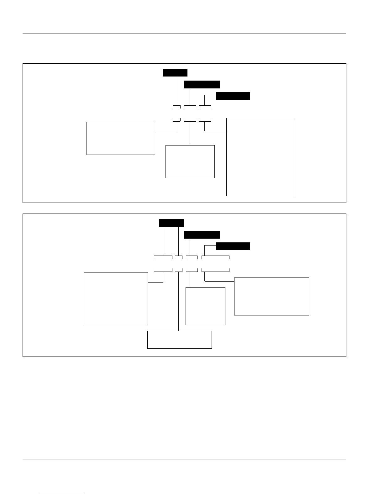
Undercounters
R - Refrigerator
F - Freezer
Sandwich / Salad Prep Table
P - Pan top (30" depth)
ST - Supertop (34" depth)
6 - 27" Wide
10 - 45" Wide
15 - 59" Wide
27 - Supertop 27"
45 - Supertop 45"
49 - Supertop 59"
Prefix
Suffix
Body Type
P–15–16
Undercounters
E - Series
Sandwich / Salad Prep Table
P Series
6 - 6 Pans
8 - 8 Pans
12 - 12 Pans
16 - 16 Pans
ST Series
2 - 2 Cutouts, 6 Pans each
3 - 3 Cutouts, 6 Pans each
4 - 4 Cutouts, 6 Pans each
Superprep
12 - 12 Pans
16 - 6 Pans
Work Tables
ST - Stainless steel flat top
LT - Sub top
STS - Stainless steel top
with backsplash
Chef Stands
LBS - Low boy chef stand
self-contained
LBR - Low boy chef stand
remote
Work Tables
R - Refrigerator
S - Self-contained
E - Series
Chef Stands
LT - Galvanized flat top
ST - Stainless steel “V” edge top
Work Tables
20 - 2 Door
30 - 3 Door
Chef Stands
2D - 2 Drawers
4D - 4 Drawers
6D - 6 Drawers
Prefix
Suffix
Body Type
STS A–30–R S E
Work Tables Only
A - Aluminum interior
S - Stainless steel interior
How to Read Model Numbers
UNDERCOUNTERS / SANDWICH / SALAD PREP TABLE EXAMPLE
WORK TABLE / CHEF STAND EXAMPLE
1-2
Part Number 14514 2/08
Page 7
Section 1 General Information
PT - Pizza Top Table
A - Aluminum Interior
A - Stainless Steel Interior
Model Prefix
Body Type
PT–A–2
1 - 1 Door
2 - 2 Door
3 - 3 Door
PIZZA PREP TABLE EXAMPLE
Part Number 14514 2/08 1-3
Page 8

General Information Section 1
Model/Serial Number Location
The McCall data plate which includes the model num ber
and serial number, as well as important electrical and
technical information, is located on the left interior wall of
the cabinet.
For convenience and quick reference, record the model
and serial numbers, voltage, and installation date in the
spaces below:
Model Number ________________________________
Serial Number ________________________________
Voltage ______________________________________
Installation Date _______________________________
Warranty Coverage
Warranty coverage on a McCall cabinet begins on the
date it is installed. Please read the warranty certificate
included with the cabinet for details.
PARTS COVERAGE
1. McCall warrants the cabinet, refrigeration, and
mechanical components against defects in mater ials
and workmanship for a period of one (1) year from
the date of original installation.
2. Refrigerator and freezer compressors are covered
for five (5) years from the date of original installation.
LABOR COVERAGE
Labor is covered for (1) year from the date of original
installation.
EXCLUSIONS FROM WARRANTY
1. Normal start-up, maintenance, adjustments, and
cleaning.
2. Damage caused by improper installation of the
McCall cabinet as outlined in this manual.
3. Labor charges resulting from the inaccessibility of
the McCall cabinet.
4. Damage to parts due to misuse, abuse, neglect, or
accidents.
5. Premium labor rates due to holidays, overtime,
travel time, mileage, etc., not specifically authorized
by McCall prior to service.
6. Miscellaneous tools or materials charges.
7. Repairs due to modifications to the McCall cabinet
or refrigeration system not authorized by McCall in
writing.
8. Claims for indirect or consequential damages,
including food spoilage or product loss.
9. Damage due to faulty or incorrect power supply,
floods, storms, or other acts or God.
WARRANTY SERVICE
To ensure warranty coverage, a qualified service
company, authorized by McCall, must perform the
warranty repair.
If the dealer the McCall cabinet was purchased from
does not perform warranty service, please contact the
McCall Service Department for assistance.
1-4
Part Number 14514 2/08
Page 9
Section 2
Important
!
Caution
PIZZA TABLES AND
REFRIGERATED BASES
E-3045-B
CHEF STANDS
COMPACT UNDERCOUNTERS
REFRIGERATOR AND FREEZERS
Front View
Side View
6.00"
(15.2 cm)
(Load Height)
Front View Side View Front View Side View
6.00"
(15.2 cm)
(Load Height)
6.00"
(15.2 cm)
(Load Height)
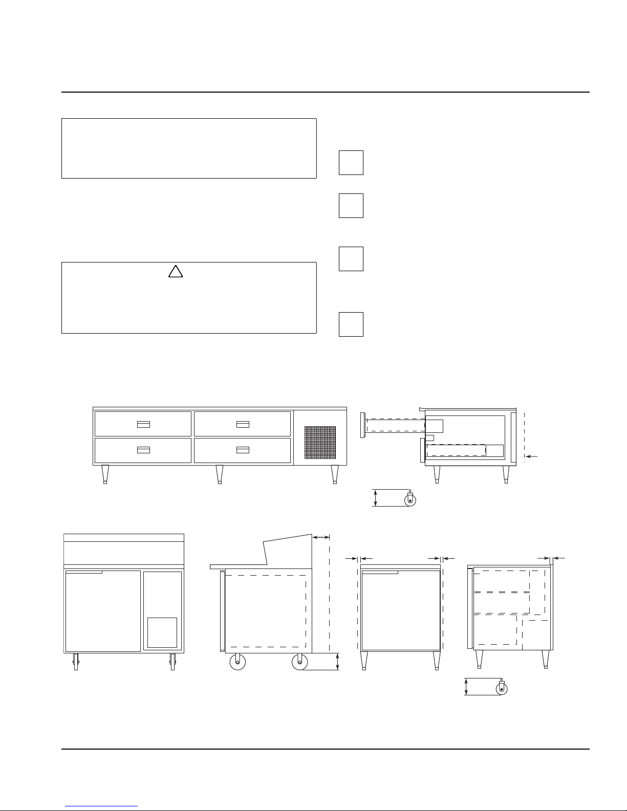
1.00"
(2.5 cm)
Line
Cover
3.00"
(7.6 cm)
6.00"
(15.2 cm)
1.00"
(2.5 cm)
Note:
1" side clearance
is recommended
on 27" and 45"
freezers.
No side clearance
is needed on
refrigerators.
1.00"
(2.5 cm)
Installation Instructions
These instructions are of the utmost importance in
assuring that the McCall cabinet operates as
designed. Follow them closely.
Pre-installation Checklist
Install the cabinet in an indoor environment
only .
Please call your local McCall dealer or the McCall
Service Department if you have any questions regardin g
proper installation.
Locating the Cabinet
When selecting a permanent location for the unit,
observe the following guidelines. Failure to do so
may cause reduced performance and efficiency,
cause damage, and/or void your warranty.
The air temperature entering the refrigerator or
freezer condenser should be between 55°F
(13°C) and 100°F (38°C).
Allow space for air circulation in the refriger ation
condensing unit compartment on refrigerator s
and freezers. The minimum space requirements
are shown below.
The floor must be strong enough to support the
weight of the cabinet and product load.
NOTE: A fully loaded cabinet can weigh more than
2,000 pounds.
Cabinet Clearances (Typical Single Door Cabinet Shown)
Part Number 14514 2/08 2-1
Page 10
Installation Instructions Section 2
!
Warning
!
Caution
!
Caution
!
Caution
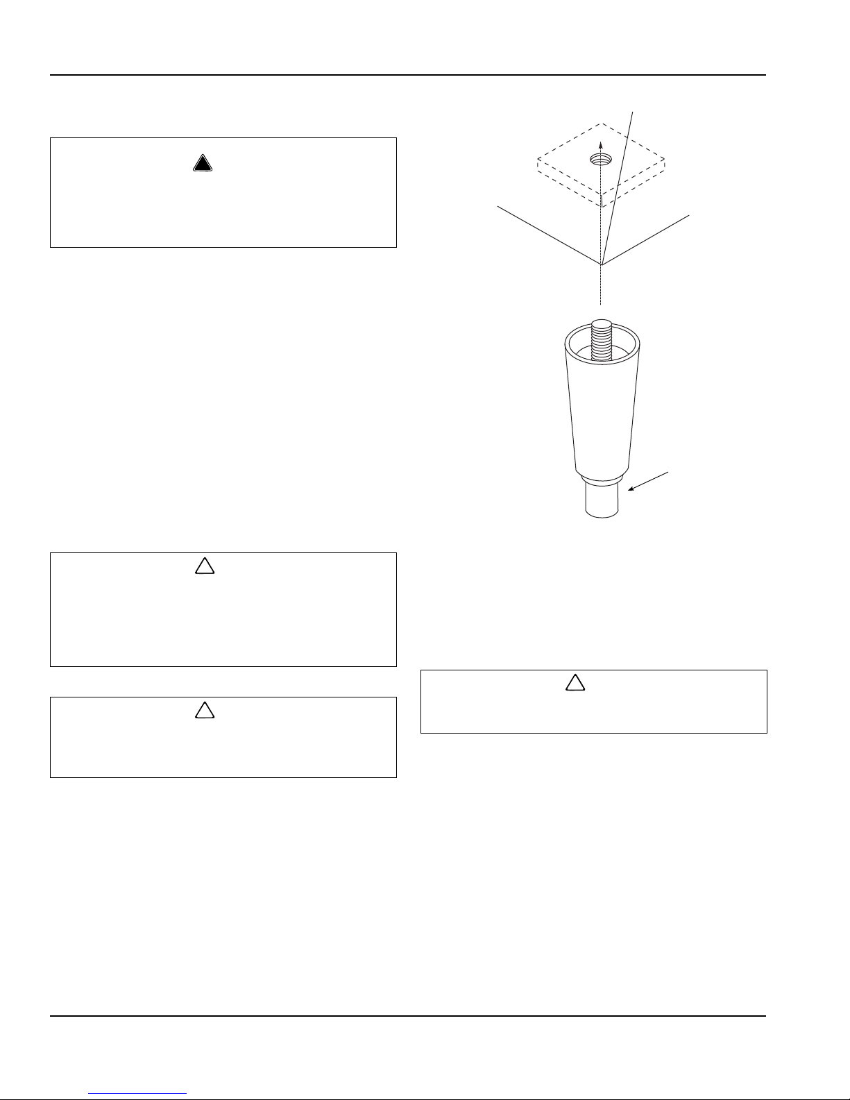
Thread Foot in
as Far as
Possible
Thread Leveling
Leg into Base of
Cabinet
SV1342
Uncrating
Never attempt to tilt the cabinet alone. Always use
two or more people when tilting the cabinet to
remove the shipping skid or to move it through
doorways.
1. Remove the bottom shipping skid using one of the
methods below:
- Lay the cabinet on its back, elevated and
supported by wooden blocks. Remove the skid
mounting bolts and separate the skid from the
cabinet.
- Tilt the cabinet from side to side and remove the
mounting bolts. Support the weight of the cabinet
apart from the skid.
2. Install the legs or casters and torque them to
360 inch-pounds (41 Nm). Refer to the drawing at
right.
3. Return the cabinet to the upright position.
4. Remove any remaining crating materials.
If the cabinet was placed on its back while moving it
or while removing the bottom shipping skid, wait at
least two hours after returning the cabinet to the
upright position before starting the refrigeration
system.
Never use sharp instruments to cut the plastic or
cardboard crating materials. Damage to the cabinet
exterior may result.
Installing Cabinet Legs
Leveling the Cabinet
The cabinet must be leveled after it is positioned in its
permanent location. This insures proper door alignment
on all cabinets, adequate condensate water drainage
and proper refrigeration system operation.
If casters are installed instead of legs, the floor must
be leveled before final positioning of the ca bin et .
1. Move the cabinet to its permanent location.
2. Place a level on top of the cabinet.
3. Turn the leveling foot of the lowest corner leg to
center the bubble in the level.
4. Adjust each of the other corners until the bubble is
centered and the cabinet is stable.
5. Re-check the cabinet from side to side and from
front to rear with the level.
2-2
Part Number 14514 2/08
Page 11

Section 2 Installation Instructions
Shelf
Support
Standard
SV1342
Extensions are required when using
18" wide (left to right) trays or pans
Tray
Slide
Note: Shelf support
standards are shown
outside for clarity.
Shelf/T ray Slide Installation
SHELVES — UNDERCOUNTER UNITS & SANDWICH/
SALAD UNITS
Shelf clips are factory-installed on undercounter
refrigerators and freezers, and on regular and super top
sandwich/salad prep units.
To install the shelves, simply unpackage the shelves
from the cardboard container and place one on each set
of clips.
SHELVES — PIZZA PREP UNITS & REFRIGERATED
WORK TABLES
Pizza prep units and work tables are factory-fitted with
shelf support standards. The shelf clips are packaged
separately and must be installed as shown in the
drawing below.
Four shelf clips are required for each shelf. Make sure
that the clips are level side-to-side and front-to-rear.
Place one shelf on each set of clips.
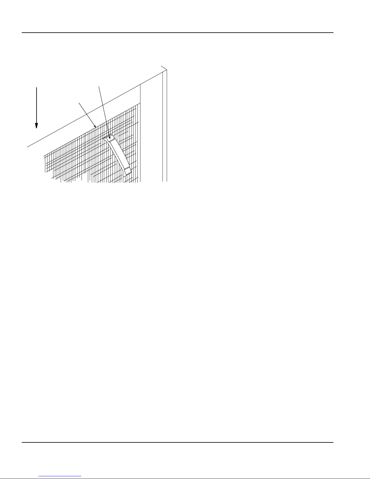
TRAY SLIDES (OPTIONAL)
Refrigerated pizza tables include a chrome plated steel
pan or tray rack (Model RA-11-T) behind one door
opening on 2- and 3-door models. All other tray slides for
pizza tables and refrigerated work tables are optional
accessories and are included only when ordered. To
install a tray slide:
1. Locate the appropriate square shelf standard holes
at the desired height.
2. Insert the tabs of each slide into the 3/8" holes in the
shelf support standards and pull it straight down to
lock it into place (refer to drawing below).
Shelf Installation
Tray Slide Installation
Part Number 14514 2/08 2-3
Page 12

Installation Instructions Section 2
SER.4
5-15P5-20P
!
Warning
Electrical
All cord-connected units must be plugged into a
grounded and properly sized electrical outlet with
appropriate overcurrent protection. Refer to the drawing
below for electrical plug configurations.
5-20P and 5-15P Electrical Plug Configurations
All permanently connected (hard wired) units are fitted
with a power junction box and 6" pigtail wires for power
connection.
Connect one end of the power line to the pi gt ail fro m the
cabinet junction box. Connect the other end to a properly
sized electrical source.
As a rule, the power lines must be enclosed inside a
conduit secured to the power junction boxes on both
ends.
NOTE: Power installation must be in compliance with the
National Electrical Code and all applicable local and
state codes.
Never use an extension cord.
Never alter the power cord or plug supplied with the
cabinet. Failure to follow this warning could result in
serious injury or death.
After the power source has been connected, turn on the
main power switch. The switch is located on the cabinet
top, behind the front louvered panel.
2-4
Part Number 14514 2/08
Page 13
Section 2 Installation Instructions
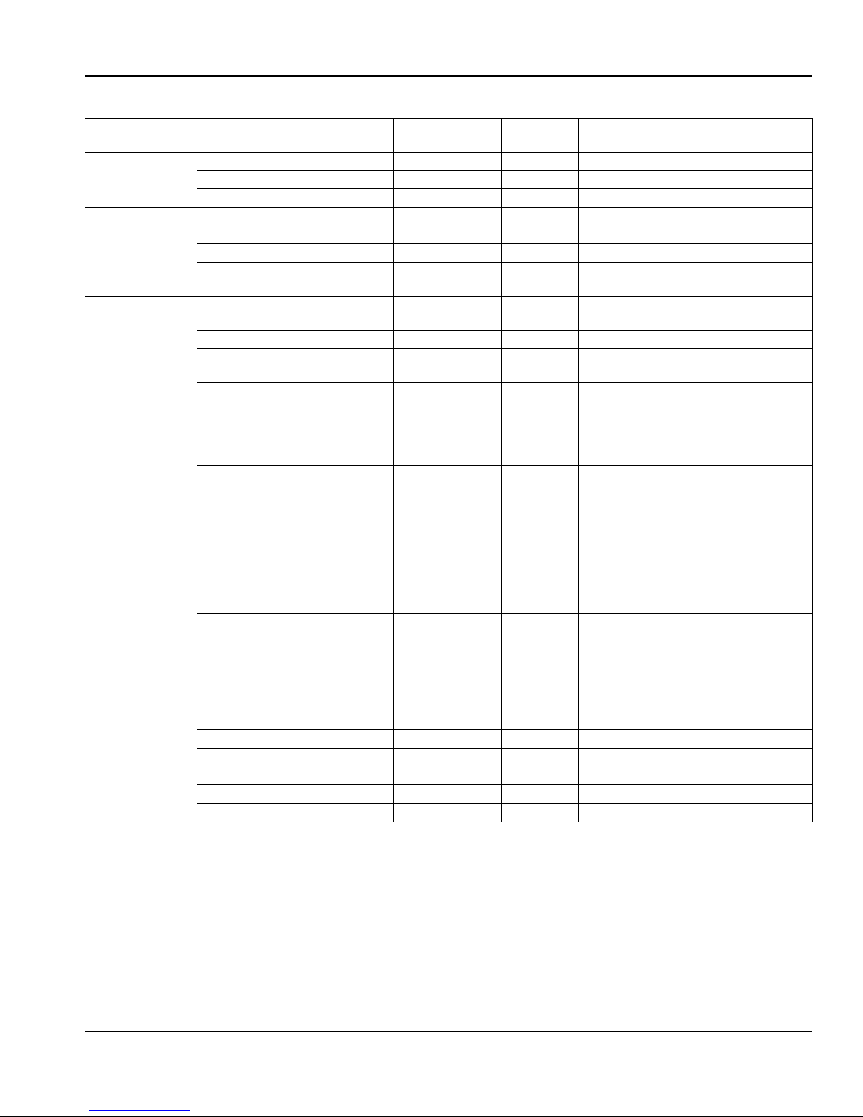
ELECTRICAL SPECIFICATIONS
Product
Type
Undercounter
Refrigerators
Undercounter
Freezers
Sandwich/Salad
Units
Refrigerated
Work
Tables
Low Boy
Chef
Stands
Pizza
Prep
Tables
Self-Contained
Base Models
R-6E, RS-6E, RSC-6E 115/60/1 6.0 15 amp NEMA 5-15
R-10E, RS-10E, RSC-10E 115/60/1 8.0 15 amp NEMA 5-15
R-15E, RS-15E, RSC-15E 115/60/1 6.0 15 amp NEMA 5-15
F-6E, FS-6E, FSC-6E 115/60/1 8.0 15 amp NEMA 5-15
F-10E, FS-10E, FSC-10E 115/60/1 8.5 15 amp NEMA 5-15
RP-6EN 115/60/1 6.0 15 amp NEMA 5-15
RP-10-6EN, RP-10-8EN,
RP-10-12EN
RP-15-8EN, RP-15-12EN,
RP-15-16EN
RST-27-2EN 115/60/1 6.0 15 amp NEMA 5-15
RST-45-2EN, RST-45-3EN,
RST-45-12EN
RST-59-3EN, RST-59-4EN,
RST-59-16EN
LTA-10-RSE, LTS-10-RSE,
STA-10-RSE, STS-10-RSE,
STSA-10-RSE, STSS-10-RSE
LTA-20-RSE, LTS-20-RSE,
STA-20-RSE, STS-20-RSE,
STSA-20-RSE, STSS-20-RSE
LTA-30-RSE, LTS-30-RSE,
STA-30-RSE, STS-30-RSE,
STSA-30-RSE, STSS-30-RSE
LTA-10-FSE, LTS-10-FSE,
STA-10-FSE, STS-10-FSE,
STSA-10-FSE, STSS-10-FSE
LTA-20-FSE, LTS-20-FSE,
STA-20-FSE, STS-20-FSE,
STSA-20-FSE, STSS-20-FSE
LTA-30-FSE, LTS-30-FSE,
STA-30-FSE, STS-30-FSE,
STSA-30-FSE, STSS-30-FSE
LBS-2D-ST, LBS-2D-LT 115/60/1 7.0 15 amp NEMA 5-15
LBS-4D-ST, LBS-4D-LT 115/60/1 10.0 15 amp NEMA 5-15
LBS-6D-ST, LBS-6D-LT 115/60/1 12.0 15 amp NEMA 5-15
PTA-10, PTS-10 115/60/1 10.0 15 amp NEMA 5-15
PTA-20, PTS-20 115/60/1 12.0 15 amp NEMA 5-15
PTA-30, PTS-30 115/60/1 16.0 20 amp NEMA 5-20
Vo ltage/Cycles/
Phase
115/60/1 8.0 15 amp NEMA 5-15
115/60/1 10.0 15 amp NEMA 5-15
115/60/1 8.0 15 amp NEMA 5-15
115/60/1 10.0 15 amp NEMA 5-15
115/60/1 7.0 15 amp NEMA 5-15
115/60/1 10.0 15 amp NEMA 5-15
115/60/1 12.0 15 amp NEMA 5-15
115/60/1 7.0 15 amp NEMA 5-15
115/60/1 12.0 15 amp NEMA 5-15
208-230/60/1 11.8 15 amp Hard Wired
Total
Amps
Maximum
Fuse Size
ANSI Electrical
Plug Configuration
Part Number 14514 2/08 2-5
Page 14

Installation Instructions Section 2
!
Caution
Important
Condensate Water Removal
McCall cabinets are equipped with condensate vaporizer
systems.
Remote units use an electrically operated system.
Most self-contained units use either an energy-free
automatic type or an electrically-operated type. No drain
connection is required.
Defrost Systems
GENERAL
Refrigerator coils are kept below the freezing point
(32°F). During compressor off time, the evaporator fan
continues to circulate 38°F refrigerator compartment air
through the evaporator coil. This air circulation raises the
coil temperature above the freezing point, melting any
accumulated frost. The run-off water is drained into the
vaporizer pan and is evaporated.
Freezer coils are defrosted electrically.
NOTE: A freezer’s evaporator fans do not run
immediately upon start-up or during and immedi at ely
following the defrost cycles. The fans start when the coil
reaches a cold temperature. This prevents th e fans from
blowing heated air on the stored products.
DEFROST TIMERS
Undercounter freezer models F-10E, FS-10E, and
FSC-10E use an adjustable defrost timer which may be
custom-set to initiate defrost periods. All other models
use non-adjustable freezer defrost timers, which
automatically initiate at pre-set intervals and for a
pre-determined duration.
DEFROST SETTINGS
The defrost timer is factory preset to defrost the
evaporator coil each day at 2:00 AM, 8:00 AM,
2:00 PM, and 8:00 PM.
If you wish to change the defrost times, remove the pins
from the outer dial and re-insert them into the desired
time slots. (Refer to drawing.)
Leave at least one hole between adjacent pins.
Defrost Timer
Set the defrost timer to defrost the cabinet during
the lowest usage periods.
SETTING DEFROST TIME
The defrost timer must be set to real time after the power
is turned on, or after a power failure.
To set the time:
1. Grasp the knob in the center of the inner dial.
2. Turn it counterclockwise to rotate the outer dial.
3. Line up the current time of day on the outer dial with
the pointer.
2-6
Part Number 14514 2/08
Page 15

Section 2 Installation Instructions
Important
Important
!
Caution
!
Caution
ADJUSTING DEFROST DURATION
The defrost cycle is terminated by a temperaturesensing switch located on the suction line, adjacent to
the evaporator coil.
The defrost duration is factory-set. Normally, no
adjustment is required. For a longer defrost time, press
down on the inner dial pointer and rotate the pointer until
the desired time lines up.
The coil defrosts only until the temperature-sensing
switch terminates the cycle, regardless of the
defrost duration that is set.
TEMPERATURE CONTROLS
The temperature controls are factory-set to maintain an
average temperature of 38°F in refrigerators, and an
average temperature of 0°F in freezers.
The temperature variance is 6-8 degrees. A freezer
should run between -2 to -3°F and +3 to +4°F. A
refrigerator should run between +35 to +36°F and +41 to
+42°F.
For a different cabinet temperature setting, turn the
temperature control knob or screw, located on the
evaporator coil/blower housing.
Setting the temperature control to the coldest setting
may cause the coil and/or air ducts to freeze and ice
up. This will eventually result in a warmer cabinet
temperature.
If ice accumulation occurs and the temperature is
lower than the guidelines, turn the control knob to a
warmer setting.
Allow the cabinet to reach proper operating
temperature before filling it with product. Do not
place hot or steaming foods in the cabinet.
Store products with high acid content (such as
lettuce, other fresh vegetables or fruits, salad
dressings, etc.) in closed containers. This will
prevent corrosion on the evaporator coil and other
metal parts in the air distribution system.
Part Number 14514 2/08 2-7
Page 16

Installation Instructions Section 2
THIS PAGE INTENTIONALLY LEFT BLANK
2-8
Part Number 14514 2/08
Page 17

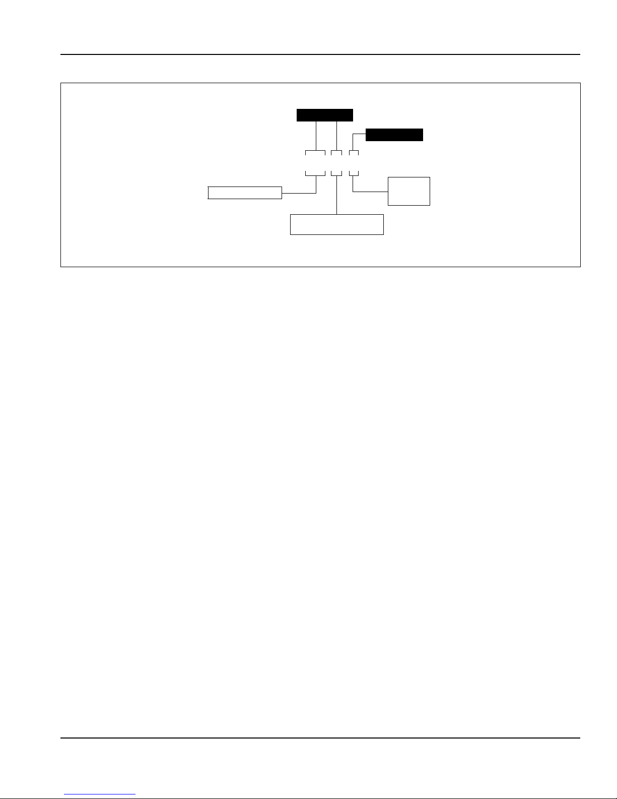
Sequence of Operation
!
Caution
Important
Supply Air
0301
Evaporator Fan
Shelf
Evaporator Coil
Shelf Compressor
Return Air
Evaporator Coil
Supply Air
Return Air
COMPACT UNDERCOUNTER
REFRIGERATOR AND FREEZERS
CHEF STANDS
PIZZA TABLES AND
REFRIGERATOR BASES
Evaporator Coil
Shelves
Return Air
Supply Air
Section 3
Operation
LOADING SHELVES
For maximum operating efficiency, load the shelves with
space between the stored items. This allows air to
circulate properly. Refer to the drawings below.
Store products with high acid content (such as
lettuce, other fresh vegetables or fruits, salad
dressings, etc.) in closed containers. This will
prevent corrosion on the evaporator coil and other
metal parts in the air distribution system.
Uncovered food will dehydrate much more rapidly
than covered food. For best food quality, always
store in covered container.
LOADING PANS
Pan-top refrigerators are designed for operation with all
pans in place, even if some pans are to be left empty.
For maximum food freshness, fill the pans only with an
amount than can be used in a specific usage period
(breakfast, lunch, dinner, etc). During non-use or
slow-use periods, close the lid cover.
Loading the Shelves
Part Number 14514 2/08 3-1
Page 18

Operation Section 3
Hinge Pin
Screw
0302
Hinge Pin
Removable
Mechanism
Hinge Mechanism
Mounting Screws
Operating Checks and Adjustments
DOOR HINGE ADJUSTMENT
1. Loosen 2 Phillips head screws on the top and
bottom hinges where the hinges fasten to the
cabinet exterior front facing.
2. Firmly press the door tight to the cabinet front while
re-tightening the hinge screws.
NOTE: For some adjustments, it may be necessary to
add shims behind the hinges.
REMOVING DOORS
Remove 2 Phillips head screws from the top door hinge
and 2 Phillips head screws from the bottom hinge.
Carefully lift the door off the cabinet front.
REHINGING DOORS — SINGLE DOOR MODELS
McCall’s one door models are factory-shippe d hinged on
the right side (facing the unit front). If it becomes
necessary to change the hinging on a door:
1. Remove 2 Phillips head screws from the top and
bottom door hinges.
2. Carefully lift the door off of the cabinet.
3. Remove the (3) screws securing the door handle
and remove the handle.
4. Turn the door 180 degrees.
Hinge Removal
5. Attach handle at the position indicated by the prepunched mounting holes.
6. Remove the hinges from the door as shown in the
drawing.
7. Position and attach the new hinge
(Part #HAH-0702-001 for the top hinge,
Part #2HAH-0704-001 for the bottom hing e ).
8. Remove and reposition the hinge cartridge
mechanism.
9. Attach the door to the cabinet using the screws
removed earlier.
10. Perform the “Door Hinge Adjustment” procedure
above.
3-2
Part Number 14514 2/08
Page 19

Section 4
!
Caution
!
Caution
!
Caution
!
Warning
!
Caution
!
Warning
Maintenance
Cleaning
EXTERIOR
Clean cabinet exterior surfaces with a solution of mild
soap and water. To minimize streaking, follow with a
fresh water rinse.
If stainless steel becomes discolored, scrub only in the
direction of the finished grain.
For high shine, see your kitchen equipment dealer for a
high-quality stainless steel polish.
Do not use steel wool, caustic soap, or abrasive
cleaners, as these may damage the metal finish.
Alcohol-based cleaners may damage the nylon door
cams.
If the cabinet has a synthetic cutting board, r emove it by
simply lifting the board straight up. Make sure the board
and the metal cabinet surface are completely dry before
replacing the cutting board.
The condensate evaporator pan, located u nderneath the
cabinet, should be cleaned periodically with soapy water
to remove any mineral deposits.
INTERIOR
Clean cabinet interior surfaces with warm water and
baking soda, applied with a cloth or sponge.
Cleaning the Condenser Coil
Disconnect electric power before cleaning. Failure
to follow this warning could result in serious injury or
death.
For efficient operation, it is very important to clean the
condenser coil surface and keep it free of dust, dirt, and
lint. McCall recommends checking the condition of the
condenser coil once a month.
The condensing unit fan draws dust, lint and small
particles to the condenser coil, where it for ms a “blanket”
on the coil surface. This is normal and should be
periodically removed.
Failure to clean and maintain the condenser coil
properly will result in reduced air circulation through
the condenser fins. This will cause reduced
efficiency, high operating pressures, and can
shorten compressor life.
CONDENSER CLEANING PROCEDURES
One or more of the following methods may be used to
clean the condenser coil surface, depending upon the
extent of the build-up on the fins.
The air duct and shelf support standards can be
removed without special tools to facilitate cleaning.
Wash door gaskets weekly with a mild soap and water
solution, followed by a fresh water rinse.
While cleaning, check the door gaskets for proper
sealing. Adjust if needed.
Do not clean cabinet interior surfaces with any
cleaning product not specifically approved for use
where food may come into contact.
Do not use steel wool, caustic soap, or abrasive
cleaners, as these may damage the metal finish.
Part Number 14514 2/08 4-1
Condenser fins are sharp. Use care when working
around them.
Method 1
Remove light build-up with a soft brush or a vacuum with
a brush attachment. Brush the condenser fins from top
to bottom, not from side to side. Shine a light through the
fins to check for dirt inside the condenser.
Method 2
Clean moderately dirty fins with compressed air, blowing
from the inside out. Follow by brushing, if necessary.
Method 3
Clean with a commercial condenser coil cleaner,
available from a kitchen equipment dealer. Follow the
directions and precautions supplied with the cleaner.
Page 20
Maintenance Section 4
fin_comb
Fin Comb
Condenser
Comb
Down Only
After cleaning, straighten any bent condenser fins with a
fin comb.
Using a Fin Comb
CLEANING THE FAN BLADES AND MOTOR
If necessary, clean the fan blades and motor with a soft
cloth. If it is necessary to wash the fan blades, cover the
fan motor to prevent moisture damage.
CLEANING THE EVAPORATOR DRAIN PAN
The evaporator drain pan, located at the bottom of the
evaporator blower panel, should be cleaned periodically
to remove any food, debris, etc. that may have fallen or
been drawn into the pan.
To clean the pan drain outlet, gently insert a pliable wire,
such as a pipe cleaner, 3-4" (7-10 cm) into the mouth of
the outlet. Remove any obvious debris in the pan
bottom.
4-2
Part Number 14514 2/08
Page 21

Section 5
!
Warning
Before Calling for Service
T roubleshooting Guide
If a problem arises during operation of your refrigerator
or freezer, follow the checklist below before calling
service. Routine adjustments and maintenance
procedures are not covered by the warranty.
Problem Possible Cause To Correct
Cabinet not running Fuse blown or circuit breaker tripped. Replace fuse or reset circuit bre aker.
Power cord unplugged. Plug in power cord.
Thermostat set too high. Set thermostat to lower temperature.
Main power switch turned off. Turn main power switch on.
Cabinet in defrost cycle.
(Freezer models)
Condensing unit runs
for long periods or
continuously
Cabinet temperature
is too high
Cabinet is noisy Loose part(s). Locate and tighten loose part(s).
Refrigerator is freezing product
Compressor will not
start — hums and trips on overload
protector
Excessive amount of warm product
placed in cabinet.
Prolonged door openings or door(s) ajar. Make sure door(s) are closed when not in
Door gasket(s) not sealing properly. Check gasket condition. Adjust door or
Dirty condenser coil. Clean the condenser coil.
Evaporator coil iced over. Turn unit off and allow coil to defrost.
Thermostat set too high. Set thermostat to lower temperature.
Poor air circulation in cabinet. Re-arrange product to allow proper air
Exterior thermometer is out of calibration. Re-calibrate thermometer.
Excessive amount of warm product
placed in cabinet.
Prolonged door openings or door(s) ajar. Make sure door(s) are closed when not in
Dirty condenser coil. Clean the condenser coil.
Evaporator coil iced over. Turn unit off and allow coil to defrost.
Tubing vibration. Insure tubing is free from contact with
Thermostat is set too low. Set thermostat to higher temperature.
Dirty condenser coil. Clean the condenser coil.
Not enough cabinet clearance for proper
refrigeration system operation.
Low voltage to cabinet. Check and correct incoming voltage to
Disconnect electric power before performing any
service. Failure to follow this warning could result in
injury or death.
Wait for defrost cycle to finish.
Allow adequate time for product to cool
down.
use. Avoid prolonged door openings.
replace gasket if necessary.
Make sure thermostat is not set too cold.
Also, check gasket condition.
circulation.
Allow adequate time for product to cool
down.
use. Avoid prolonged door openings.
Make sure thermostat is not set too cold.
Also, check gasket condition.
other tubing or components.
Move cabinet or make other adjustments
to gain proper cabinet clearances.
cabinet.
Part Number 14514 2/08 5-1
Page 22

Before Calling for Service Section 5
THIS PAGE INTENTIONALLY LEFT BLANK
5-2
Part Number 14514 2/08
Page 23

Page 24

© 2008 Manitowoc
Continuing product improvements
may necessitate change of
specifications without notice.
Part Number 14514 2/08
McCall Refrigeration, Inc.
81 West Holly Street
Parsons, TN 38363, USA
Ph: 731-847-5365 Fax: 731-847-9012
Visit us online at: www.manitowocfsg.com
 Loading...