

Page 1
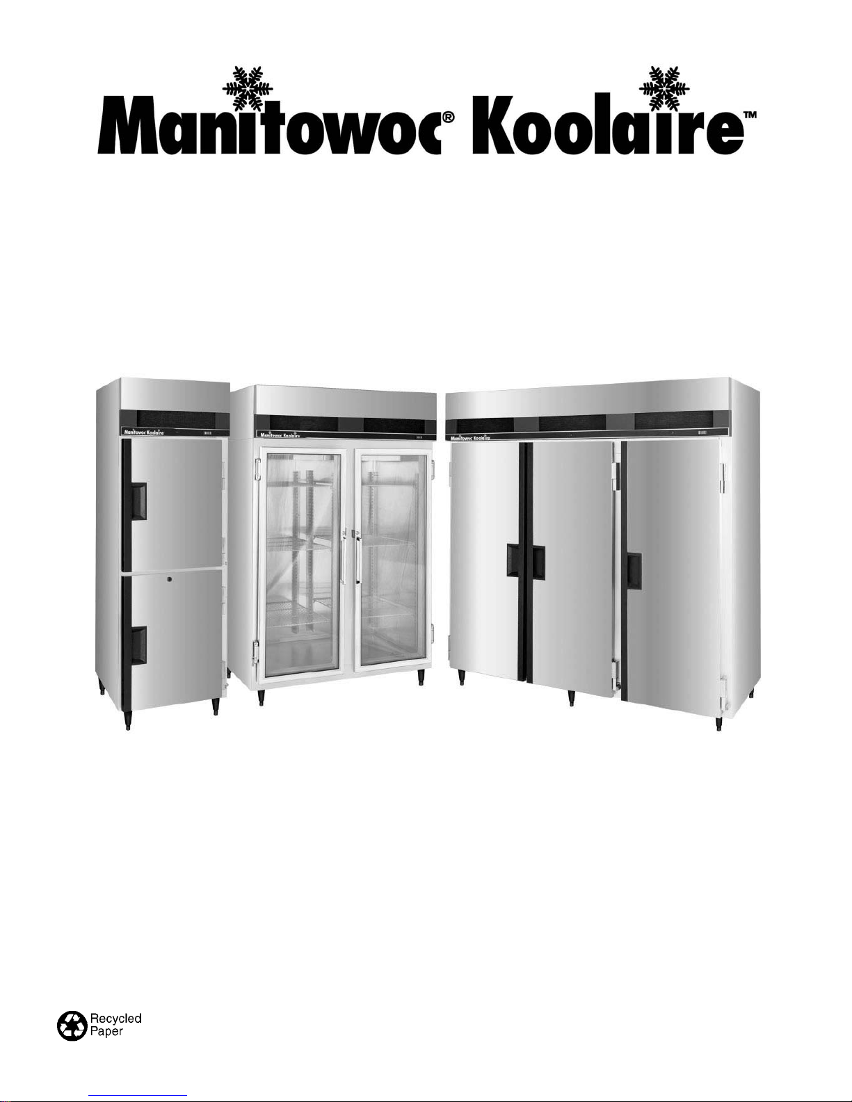
Reach-In Refrigerators and Freezers
Installation, Use and Care Guide
This manual contains important information regarding the installation and upkeep of your new Koolaire refrigerator or freezer.
Please read the manual thoroughly prior to equipment handling, set-up, operation, and maintenance.
Part No. 80-0009-3
Page 2
Safety Notices
Procedural Notices
As you work on a Manitowoc Koolaire reach-in, be
sure to pay close attention to the safety notices in this
manual. Disregarding the notices may lead to serious
injury and/or damage to the equipment.
Throughout this manual, you will see the following
types of safety notices:
WARNING
Text in a Warning box alerts you to a potential
personal injury situation. Be sure to read the
Warning statement before proceeding, and work
carefully.
CAUTION
Text in a Caution box alerts you to a situation in
which you could damage the equipment. Be sure to
read the Caution statement before proceeding, and
work carefully.
As you work on a Manitowoc Koolairereach-in, be
sure to read the procedural notices in this manual.
These notices supply helpful information which may
assist you as you work.
Throughout this manual, you will see the following
types of procedural notices:
Important
Text in an Important box provides you with
information that may help you perform a procedure
more efficiently. Disregarding this information will
not cause damage or injury, but it may slow you
down as you work.
NOTE: Text set off as a Note provides you with
simple, but useful, extra information about the
procedure that you are performing.
About This Manual
This manual contains important information on the installation, use, and upkeep of your new your Manitowocâ
Koolaire reach-in. Each reach-in has been carefully inspected for the highest possible quality. With proper
installation and care, you will enjoy many years of reliable performance.
Please read and understand the information contained in this manual prior to installation, start-up, and operation.
If you do not understand any part of the information contained in this manual, please contact your Manitowocâ
Koolaire dealer or call the factory at 1-877-582-5086.
Page 3

Table of Contents
Table of Contents
Section 1 - Warranty
Model/Serial Number Location ........................................................................................................................ 1-1
Warranty ............................................................................................................................................................ 1-1
Warranty Service ............................................................................................................................................... 1-1
Section 2 - Installation
General................................................................................................................................................................ 2-1
Positioning the Cabinet...................................................................................................................................... 2-1
Heat of Rejection................................................................................................................................................ 2-1
Uncrating ............................................................................................................................................................ 2-2
Leveling the Cabinet.......................................................................................................................................... 2-3
Shelf/Tray Slide Installation ............................................................................................................................. 2-3
Section 3 - Start-Up
Electrical Requirements .................................................................................................................................... 3-1
Electrical Specifications..................................................................................................................................... 3-2
Condensate Water Removal ............................................................................................................................. 3-3
Defrost Systems
General.......................................................................................................................................................... 3-3
Defrost Settings ............................................................................................................................................ 3-3
Setting Time of Day ..................................................................................................................................... 3-3
Adjusting Defrost Duration ........................................................................................................................ 3-3
Temperature Controls
Refrigerators and Freezers ......................................................................................................................... 3-4
Loading Shelves ................................................................................................................................................. 3-4
Continued on next page...
i
Page 4

Table of Contents
Table of Contents (cont.)
Section 4 - Cleaning
Exterior ............................................................................................................................................................... 4-1
Interior ................................................................................................................................................................ 4-1
Cleaning the Condenser Coil ........................................................................................................................... 4-2
Section 5 - Adjustments and Calibrations
Adjustments
Solid Door Adjustment................................................................................................................................ 5-1
Glass Door Adjustment ............................................................................................................................... 5-1
Calibrations
Thermometer Calibration ........................................................................................................................... 5-2
Section 6 - Before Requesting Service
Troubleshooting Guide...................................................................................................................................... 6-1
ii
Page 5
Section 1 Warranty
Section 1
Warranty
Model/Serial Number Location
The Koolaire data plate, which includes the model
number and serial number, as well as important
electrical and technical information, is located on the
left interior wall of the cabinet at approximately eye
level.
For convenience and quick reference, record the
model and serial numbers, voltage, and installation
date in the spaces below:
Model Number
Serial Number
Voltage
Installation Date
Warranty
Warranty coverage on a Koolaire reach-in begins
on the date it is installed. Please read the warranty
certificate included with the cabinet for details.
PARTS COVERAGE
1. A Koolaire reach-in cabinet and the
refrigeration and mechanical components are
warranted against defects in materials and
workmanship for a period of two (2) years from
the date of original installation.
2. The evaporator coil and compressor are covered
by an additional three (3) years (five years total)
warranty beginning on the date of the original
installation.
Note: The additional three year evaporator coil
warranty does not apply to parts such as fan motors,
defrost elements, housings, electrical wiring, or
controls that are attached to the evaporator coil.
EXCLUSIONS FROM WARRANTY
1. Normal start-up, maintenance, adjustments, and
cleaning.
2. Interior cabinet light bulb.
3. Repairs due to unauthorized modifications to the
Refrigeration System/Reach-In Cabinet or the use
of non-standard parts without prior written
approval.
4. Damage caused by improper installation of the
Reach-In cabinet, electrical supply, water supply
or drainage, or damage caused by floods, storms,
or other acts of God.
5. Premium labor rates due to holidays, overtime,
travel time, mileage flat rate, service call charges
and miscellaneous tools and material charges not
listed on the payment schedule. Additional labor
charges resulting from inaccessibility of the
Reach-In are also excluded.
6. Parts or assemblies subjected to misuse, abuse,
neglect or accidents.
7. Damage to the interior of cabinet or refrigeration
system as a result of storing open acidic food
containers.
8. Claims for special indirect or consequential
damages, including food spoilage or product loss.
Warranty Service
To insure warranty coverage, a qualified service
company must perform the warranty repair.
If the dealer the Koolaire reach-in was purchased
from does not perform warranty service, please call 1877-582-5086 for assistance.
LABOR COVERAGE
Labor is covered to repair or replace defective
components for two (2) years from the date of the
original installation.
1-1
Page 6

Warranty Section 1
THIS PAGE INTENTIONALLY LEFT BLANK
1-2
Page 7
Section 2 Installation
Section 2
Installation
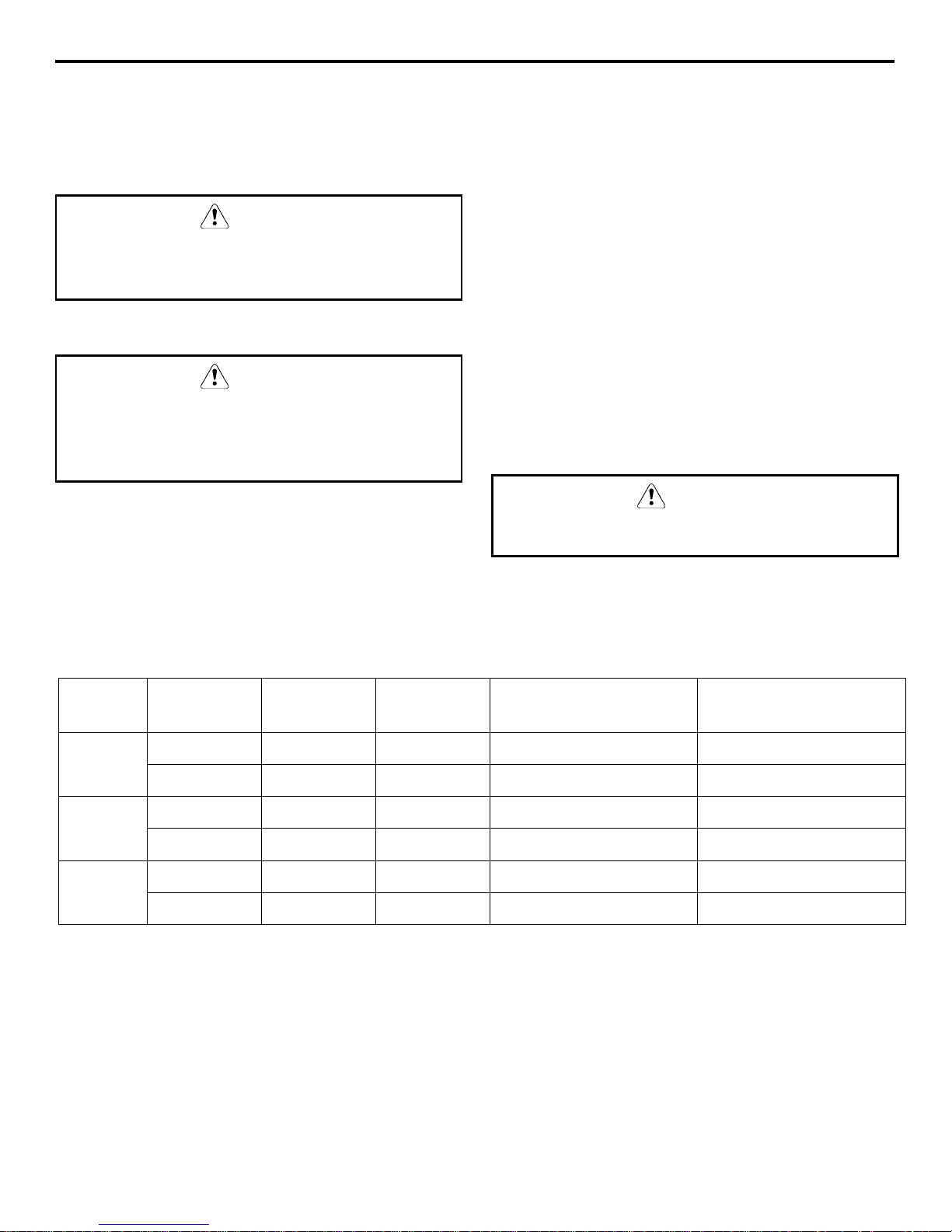
General
CAUTION
These instructions are of the utmost importance in
assuring that the Manitowoc Koolaire cabinet
operates as designed, and must be followed closely.
Positioning the Cabinet
CAUTION
When selecting a permanent location for the
cabinet, observe the following guidelines. Failure to
do so may cause reduced performance and
efficiency, cause damage, and void your warranty.
Heat of Rejection
CABINET LOCATION GUIDELINES
• Install the cabinet in an indoor environment only.
• The air temperature entering the refrigerator or
freezer condenser should be between 55°F (13°C)
and 100°F (38°C).
• Allow space for air circulation in the refrigeration
condensing unit compartment on refrigerators and
freezers. The minimum space requirements are:
• 10” (25 cm) on top
• 4” (10 cm) at the back
• 4” (10 cm) on each side
• The floor must be strong enough to support the
weight of the cabinet and product load.
CAUTION
A fully loaded reach-in cabinet can weigh more
than 3,000 pounds.
All refrigeration equipment rejects heat through the condenser. It is helpful to know the amount of heat rejected,
to determine the additional load that will be placed on air conditioning equipment.
Model Solid Door Half Door Glass Door Refrigerator BTU Per
Hour
1 Door KR-1 KR-101 2600 1700
KR-1GD 3780 N/A
2 Door KR-2 KR-201 2600 2840
KR-2GD 4600 N/A
3 Door KR-3 KR-301 3780 3450
KR-3GD 5580 N/A
Freezer BTU Per Hour
2-1
Page 8

Installation Section 2
Uncrating
WARNING
Never attempt to tilt the cabinet alone. Always use
two or more people when tilting the cabinet to
remove the shipping skid or to move it through
doorways.
1. Remove the bottom shipping skid using one of
the methods below:
• Lay the cabinet on its back, elevated and
supported by wooden blocks. Remove the
skid mounting bolts and separate the skid
from the cabinet.
• Tilt the cabinet from side to side and remove
the mounting bolts. Support the weight of the
cabinet apart from the skid.
2. Install the legs or casters and torque them to 360
inch-pounds. Refer to the drawing at right.
3. Return the cabinet to the upright position.
4. Remove any remaining crating materials.
THREAD LEVELING
LEG INTO BASE OF
CABINET
THREAD FOOT IN
AS FAR AS
POSSIBLE
SV1342
CAUTION
If the cabinet was placed on its back while moving
it or while removing the bottom shipping skid, wait
at least two hours after returning the cabinet to the
upright position before starting the refrigeration
system.
CAUTION
Never use sharp instruments to cut the plastic or
cardboard crating materials. Damage to the cabinet
exterior may result.
Installing Cabinet Legs
2-2
Page 9

Section 2 Installation
Leveling the Cabinet
The cabinet must be leveled after it is positioned in
its permanent location. This insures proper door
alignment on all cabinets, and adequate condensate
water drainage and proper refrigeration system
operation.
Leveling the Cabinet
CAUTION
If casters are installed instead of legs, the floor must
be leveled before final positioning of the cabinet.
1. Place a level on top of the cabinet.
2. Turn the leveling foot of the lowest corner leg to
center the bubble in the level.
3. Adjust each of the other corners until the bubble
is centered and the cabinet is stable.
4. Re-check the cabinet from side to side and from
front to rear with the level. Adjust the leg levelers
as necessary.
Shelf/Tray Slide Installation
SHELVES
1. Determine the desired shelf location.
SHELF
CLIP
Shelf Installation
TRAY SLIDES
Tray slides are optional accessories and must be
ordered separately. To install a tray slide:
1. Locate the appropriate square shelf standard holes
at the desired height.
2. Insert the tabs of each slide into the 3/8" holes in
the shelf support standards and pull it straight
down to lock it into place (Refer to drawing
below).
SHELF
SUPPORT
STANDARD
SER.3
NOTE: The shelves may be located at any position in
1" increments. Optimum spacing is one shelf near the
bottom of the cabinet, one shelf near center height,
and one shelf at eye level (Refer to drawing).
2. Install four clips per shelf, one at each corner. The
shelf clips slip into the 3/8" holes and slide down.
3. Make sure that the clips are level from side to
side and from front to rear at each corner.
4. Install the shelves with the smaller wires running
from front to back.
TRAY
SLIDE
NOTE: SHELF SUPPORT
STANDARDS ARE
SHOWN OUTSIDE
FOR CLARITY
Tray Slide Installation
SHELF
SUPPORT
STANDARD
SER.2
2-3
Page 10

Installation Section 2
THIS PAGE INTENTIONALLY LEFT BLANK
2-4
Page 11

Section 3 Start-Up
Section 3
Start Up
Electrical Requirements
All cord-connected units should be plugged into a
grounded and properly sized electrical outlet with
appropriate overcurrent protection. Refer to the
drawing below for electrical plug configurations.
5-20P 5-15P
SER.4
5-20P and 5-15P Electrical Plug Configurations
All permanently connected (hard-wired) units are
fitted with a power junction box and 6” pigtail wires
for power connection.
Connect one end of the power line to the pigtail from
the cabinet junction box. Connect the other end to a
properly sized electrical source.
As a rule, the power lines must be enclosed inside a
conduit secured to the power junction boxes on both
ends.
CAUTION
Power installation must be in compliance with the
National Electrical Code and all applicable local
and state codes.
WARNING
Never use an extension cord.
Never alter the power cord or plug supplied with
the cabinet.
After the power source has been connected, turn on
the main power switch. The switch is located on the
cabinet top, behind the front panel.
3-1
Page 12

Start-Up Section 3
Electrical Specifications
REACH-IN
REFRIGERATORS
Full Door
Half Door
Glass Door
Model Voltage/ Phase/Cycles Total
Amps
KR-1 115/60/1 9.9 15 amp 5-15P
230/50/1 ** ** **
KR-2 115/60/1 10.4 15 amp 5-15P
230/50/1 ** ** **
Minimum
KR-3 *115 & 208-230/60/1
230/50/1 ** ** **
KR-101 115/60/1 9.9 15 amp 5-15P
230/50/1 ** ** **
KR-102 115/60/1 10.4 15 amp 5-15P
230/50/1 ** ** **
KR-103 *115 & 208-230/60/1
230/50/1 ** ** **
KR-1GD 115/60/1 14.7 20 amp 5-20P
230/50/1 ** ** **
KR-2GD 115/60/1 16.0 20 amp 5-20P
230/50/1 ** ** **
KR-3GD *115 & 208-230/60/1
230/50/1 ** ** **
circuit amps
15.1
Minimum
circuit amps
15.1
Minimum
circuit amps
15.3
Maximum
Fuse Size
20 amp Hard-Wired
20 amp Hard-Wired
20 amp Hard-Wired
ANSI Electrical
Plug Configuration
REACH-IN
FREEZER
Full Door
Half Door
Model Voltage/ Phase/Cycles Total
Amps
KF-1 115/60/1 12.4 20 amp 5-15P
230/50/1 ** ** **
KF-2 115/60/1 16 20 amp 5-20-P
230/50/1 ** ** **
Minimum
KF-3 *115 & 208-230/60/1
230/50/1 ** ** **
KF-101 115/60/1 12.4 20amp 5-15P
230/50/1 ** ** **
KF-201 208/230/60/1 16 20 amp 5-20-P
230/50/1 ** ** **
KF-301 *115 & 208-230/60/1
230/50/1 ** ** **
circuit amps
15.8
Minimum
circuit amps
15.8
Maximum
Fuse Size
20 amp Hard-Wired
20 amp Hard-Wired
ANSI Electrical
Plug Configuration
* 4 wire dual voltage required: 115 Volt for the lights and fans, 208-230 Volt for the compressor.
** Data not available at time of printing.
3-2
Page 13

Section 3 Start-Up
Condensate Water Removal
(Refrigerators and Freezers)
Manitowoc cabinets are equipped with a condensate
vaporizer system. This system uses energy-saving hot
gas supplied by the refrigeration system lines. No
drain connection is required.
Defrost Systems
GENERAL
Refrigerator coils operate at tmperatures below
freezing (32°F). During compressor “off” time, the
evaporator fan continues to circulate 38°F refrigerator
compartment air through the evaporator coil. This air
circulation raises the coil temperature above the
freezing point, melting any frost that may have
accumulated.
The run-off water is drained into the vaporizer pan
and is evaporated by the hot gas refrigeration line
during compressor “on” time.
24 HOUR
DIAL
2 HOUR
DIAL
SV1080
Defrost Time Clock
Important
Set the defrost timer to defrost the reach-in during
the lowest usage periods.
Freezer coils are defrosted electrically at userdetermined times.
NOTE: A freezer’s evaporator fans do not run
immediately upon start-up or during and immediately
following the defrost cycles. The fans start when the
coil temperature falls below freezing. This prevents
the fans from blowing moisture or heated air on the
stored products.
DEFROST SETTINGS
The defrost timer is factory preset to defrost the
evaporator coil each day at 2:00 AM, 8:00 AM,
2:00 PM, and 8:00 PM.
If you wish to change the defrost times, remove the
pins from the outer dial and re-insert them into the
desired time slots. (Refer to drawing.)
CAUTION
Leave at least one hole between adjacent pins.
SETTING TIME OF DAY
The defrost timer must be set to “real time” after the
power is turned on, or after a power failure.
To set the time:
1. Grasp the knob in the center of the inner dial.
2. Turn it counterclockwise to rotate the outer dial.
3. Line up the current time of day on the outer dial
with the pointer.
ADJUSTING DEFROST DURATION
The defrost cycle is terminated by a temperaturesensing switch located on the suction line, adjacent to
the evaporator coil.
The defrost duration is factory-set. Normally, no
adjustment is required. For a longer defrost time,
press down on the inner dial pointer and rotate the
pointer until the desired time lines up.
Important
The coil defrosts only until the temperature-sensing
switch terminates the cycle, regardless of the
defrost duration that is set.
3-3
Page 14

Start-Up Section 3
Temperature Control
REFRIGERATORS AND FREEZERS
The temperature controls are factory-set to maintain
an average temperature of 38°F (3°C) in refrigerators,
and an average temperature of 0°F (18°C) in freezers.
The temperature variance is 6-8 F (2°-4°C) degrees.
A freezer should run between -2°F to +4°F (3°C to 15°C). A refrigerator should run between +35° to
+42°F (1°C to 5°C).
For a different cabinet temperature setting, turn the
temperature control knob, located behind the front
cabinet louver.
CAUTION
Setting the temperature control to the coldest
setting may cause the coil and/or air ducts to freeze
and ice up. This will eventually result in a warmer
cabinet temperature.
If ice accumulation occurs and the temperature is
lower than the guidelines, turn the control knob to a
warmer setting.
Loading Shelves
For maximum operating efficiency, load the shelves
with space between the stored items. This allows air
to circulate properly.
CAUTION
Do not store more than 250 pounds of product on
any shelf and no more than 800 pounds of product
per cabinet.
CAUTION
Store products with high acid content (such as
lettuce, other fresh vegetables or fruits, salad
dressings, etc.) in closed containers. This will
prevent corrosion on the evaporator coil and other
metal parts in the air distribution system.
Important
Uncovered food will dehydrate much more rapidly
than covered food. For best food quality, always
store in covered container.
CAUTION
Allow the reach-in to reach proper operating
temperature before filling it with product. Do not
place hot or steaming foods in the cabinet.
3-4
Page 15

Section 4 Cleaning
Section 4
Cleaning
Exterior
Clean cabinet exterior surfaces with a solution of
mild soap and water. To minimize streaking, follow
with a fresh water rinse.
If stainless steel becomes discolored, scrub only in
the direction of the finished grain.
For high shine, see your kitchen equipment dealer for
a high-quality stainless steel polish.
CAUTION
Do not use steel wool, caustic soap, or abrasive
cleaners, as these may damage the metal finish.
Alcohol-based cleaners may damage the nylon door
cams.
Interior
Clean cabinet interior surfaces with warm water and
baking soda, applied with a cloth or sponge.
The shelves and shelf support standards can be
removed without special tools to facilitate cleaning.
Wash door gaskets weekly with a mild soap and
water solution, followed by a fresh water rinse.
While cleaning, check the door gaskets for proper
sealing. Adjust if needed.
CAUTION
Never use cleaners that are not approved for use
where food may come into contact with cabinet
interior surfaces.
CAUTION
Do not use steel wool, caustic soap, or abrasive
cleaners, as these may damage the metal finish.
4-1
Page 16

Cleaning Section 4
Cleaning the Condenser Coil
CONDENSER CLEANING PROCEDURE
WARNING
Disconnect electric power before cleaning.
A dirty condenser restricts airflow, resulting in
excessively high operating temperatures. This reduces
efficiency and shortens component life.
The washable aluminum filter is designed to catch
dust, dirt, lint and grease. This helps keep the
condenser clean. For efficient operation, it is very
important to clean the condenser coil surface and
keep it free of dust, dirt, and lint.
The condition of the air filter and condenser coil
should be checked monthly.
CAUTION
Failure to clean and maintain the condenser coil
properly will result in reduced air circulation
through the condenser fins. This will cause reduced
efficiency, high operating pressures, and possible
shortened compressor life.
Use this procedure to clean the condenser monthly:
1. Remove and clean the filter with a mild soap and
water solution.
2. Clean the outside of the condenser with a soft
brush or a vacuum with a brush attachment. Clean
from top to bottom not side to side. Be careful not
to bend the condenser fins.
3. Shine a flashlight through the condenser to check
for dirt between the fins. If dirt remains:
A. Blow compressed air through the condenser
from the inside. Be careful not to bend the fan
blades.
B. Use a commercial condenser coil cleaner.
Follow the directions and cautions supplied
with the cleaner.
Repeat step 3 until all dirt is removed.
After cleaning, straighten any bent condenser fins
with a fin comb.
WARNING
Condenser fins are sharp. Use care when working
around them.
FIN COMB
CONDENSER
COMB
DOWN
ONLY
Using a Fin Comb
WARNING
Disconnect electric power before cleaning.
CLEANING THE FAN BLADES AND MOTOR
If necessary, clean the fan blades and motor with a
soft cloth. If it is necessary to wash the fan blades,
cover the fan motor to prevent moisture damage.
4-2
Page 17

Section 5 Adjustments and Calibrations
Section 5
Adjustments and Calibrations
Adjustments
Cabinet doors may require some adjustment after a
period of usage, depending upon the frequency of
door openings. This is normal. Follow the appropriate
procedure below:
SOLID DOOR ADJUSTMENT
1. Remove the metal hinge covers that conceal the
three hinge mounting screws. Gently pry it off
with a flat-bladed screwdriver.
HINGE
MOUNTING
SCREWS
DOOR
HINGE
GLASS DOOR ADJUSTMENT
To adjust the spring tension:
1. Locate the adjustment bushing on the hinges. This
bushing is on top of the hinge for right-hand
doors and on the bottom for left-hand doors.
2. Insert a small nail (1/8”) into a hole in the
adjustment bushing. Wind the bushing clockwise
until the pin can be removed from the bushing.
INSERT A
SMALL NAIL
TURN
CLOCKWISE
HINGE
COVER
E-3044-B
Hinge/Hinge Cover
2. Loosen the three hinge mounting screws
approximately two rotations, using a Phillips
screwdriver.
3. While a second person firmly pushes the door
closed to the front face of the cabinet, re-tighten
the screws.
4. Re-install the hinge covers.
ADJUST MENT
BUSHING
Hinge Adjustment
3. Continue winding the bushing clockwise until the
desired tension is achieved.
4. Re-insert the bushing pin.
CAUTION
Do not over-tighten the hinge spring.
Manitowoc recommends adjusting the hinge
adjustment bushings one hole at a time.
5-1
Page 18

Adjustments and Calibrations Section 5
Thermometer Calibration
Occasionally, the rigors of shipping and installation
can shift the thermometer out of proper adjustment.
If the accuracy of the thermometer is in question,
place another thermometer inside the cabinet at
approximately mid-height and compare the readings.
If the thermometer requires adjustment, follow the
procedure below.
1. Gently pry off the clear thermometer cover lens
with a small flat-bladed screwdriver.
2. While carefully holding the dial indicator needle
with one hand, turn the slotted center pivot with a
flat-bladed screwdriver. Turn clockwise to
decrease the reading and counterclockwise to
increase the reading.
3. Replace the clear thermometer cover lens by
pressing it into place around the perimeter.
5-2
Page 19

Section 6 Before Requesting Service
Section 6
Before Requesting Service
Troubleshooting Guide
Before requesting any service on your Manitowoc
cabinet, please check the following points.
This guide is not comprehensive; it is intended as a
reference for solutions to common problems.
Symptom Possible Cause Corrective Action
Cabinet not running Fuse blown or circuit breaker tripped. Replace fuse or reset circuit breaker.
Power cord unplugged. Plug in power cord.
Thermostat set too high. Set thermostat to lower temperature.
Main power switch turned off. Turn main power switch on.
Cabinet in defrost cycle. (Freezer models) Wait for defrost cycle to finish.
Condensing unit runs
for long periods or
continuously Prolonged door openings or door(s) ajar. Make sure door(s) are closed when not in
Cabinet temperature Thermostat set too high. Set thermostat to lower temperature.
is too high Poor air circulation in cabinet. Re-arrange product to allow proper air
Cabinet is noisy Loose part(s). Locate and tighten loose part(s).
Refrigerator is freezing
product
Compressor will not Dirty condenser coil. Clean the condenser coil.
start - hums and trips
on overload
protector
Excessive amount of warm product
placed in cabinet.
Door gasket(s) not sealing properly. Check gasket condition. Adjust door or
Dirty condenser coil. Clean the condenser coil.
Evaporator coil iced over. Turn unit off and allow coil to defrost.
Exterior thermometer is out of calibration. Re-calibrate thermometer.
Excessive amount of warm product
placed in cabinet.
Prolonged door openings or door(s) ajar. Make sure door(s) are closed when not in
Dirty condenser coil. Clean the condenser coil.
Evaporator coil iced over. Turn unit off and allow coil to defrost.
Tubing vibration. Insure tubing is free from contact with
Thermostat is set too low. Set thermostat to higher temperature.
Not enough cabinet clearance for
proper refrigeration system operation.
Low voltage to cabinet. Check and correct incoming voltage to
Disconnect electric power before performing any
service.
Allow adequate time for product to cool
down.
use. Avoid prolonged door openings.
replace gasket if necessary.
Make sure thermostat is not set too cold.
Also, check gasket condition.
circulation.
Allow adequate time for product to cool
down.
use. Avoid prolonged door openings.
Make sure thermostat is not set too cold.
Also, check gasket condition.
other tubing or components.
Move cabinet or make other
adjustments to gain proper cabinet
clearances.
cabinet.
WARNING
6-1
Page 20

Before Requesting Service Section 6
THIS PAGE INTENTIONALLY LEFT BLANK
6-2
Page 21

Page 22

We reserve the right to make product
improvements at any time.
MANITOWOCâ Koolaire.
81 West Holly St.
Parsons TN. 38363
Phone: (887) 582-5086
Service Fax: (901) 847-5552
Web Site - www.manitowocice.com
Specifications and design are subject
to change without notice.
ã2000 Manitowocâ Koolaire.
Litho in USA
 Loading...