

Manitowoc KY0350A, KD0250A, KY0250A, KD0350A, KD0350W Installation, Operation And Maintenance Manual
...Page 1
Ice Machines
K Series
Installation, Operation and Maintenance Manual
Part Number 000012545 Rev 02 11/16
Page 2

Page 3

Safety Notices
Safety Notices
Read these precautions to prevent personal injury:
• Read this manual thoroughly before operating,
installing or performing maintenance on the
equipment. Failure to follow instructions in this
manual can cause property damage, injury or death.
• Routine adjustments and maintenance procedures
outlined in this manual are not covered by the
warranty.
• Proper installation, care and maintenance are essential
for maximum performance and trouble-free operation
of your equipment.
Visit our website www.kool-aire.com for manual
updates, translations, or contact information for
service agents in your area.
• This equipment contains high voltage electricity and
refrigerant charge. Installation and repairs are to be
performed by properly trained technicians aware of
the dangers of dealing with high voltage electricity
and refrigerant under pressure. The technician must
also be certified in proper refrigerant handling
and servicing procedures. All lockout and tag out
procedures must be followed when working on this
equipment.
• This equipment is intended for indoor use only. Do
not install or operate this equipment in outdoor areas.
Warning
n
Follow these electrical requirements during
installation of this equipment.
• All field wiring must conform to all applicable
codes of the authority having jurisdiction. It is
the responsibility of the end user to provide the
disconnect means to satisfy local codes. Refer to rating
plate for proper voltage.
• This appliance must be grounded.
• This equipment must be positioned so that the plug is
accessible unless other means for disconnection from
the power supply (e.g., circuit breaker or disconnect
switch) is provided.
• Check all wiring connections, including factory
terminals, before operation. Connections can become
loose during shipment and installation.
Warning
n
Follow these precautions to prevent personal injury
during installation of this equipment:
• Installation must comply with all applicable
equipment fire and health codes with the authority
having jurisdiction.
• To avoid instability the installation area must be
capable of supporting the combined weight of the
equipment and product. Additionally the equipment
must be level side to side and front to back.
• Ice machines require a deflector when installed on
an ice storage bin. Prior to using a non-OEM ice
storage system with this ice machine, contact the
bin manufacturer to assure their ice deflector is
compatible.
• Remove all removable panels before lifting and
installing and use appropriate safety equipment
during installation and servicing. Two or more people
are required to lift or move this appliance to prevent
tipping and/or injury.
• Do not damage the refrigeration circuit when
installing, maintaining or servicing the unit.
• Connect to a potable water supply only.
• This equipment contains refrigerant charge.
Installation of the line sets must be performed by
a properly trained and EPA certified refrigeration
technician aware of the dangers of dealing with
refrigerant charged equipment.
• Legs or casters must be installed and the legs/casters
must be screwed in completely. When casters are
installed the mass of this unit will allow it to move
uncontrolled on an inclined surface. These units must
be tethered/secured to comply with all applicable
codes. Swivel casters must be mounted on the front
and rigid casters must be mounted on the rear. Lock
the front casters after installation is complete.
• Some 50 Hz models may contain up to 150 grams
of R290 (propane) refrigerant. R290 (propane)
is flammable in concentrations of air between
approximately 2.1% and 9.5% by volume (LEL lower
explosion limit and UEL upper explosion limit). An
ignition source at a temperature higher than 470°C is
needed for a combustion to occur. Refer to nameplate
to identify the type of refrigerant in your equipment.
Only trained and qualified personnel aware of the
dangers are allowed to work on the equipment.
Page 4
Warning
n
Follow these precautions to prevent personal injury
while operating or maintaining this equipment:
• Read this manual thoroughly before operating,
installing or performing maintenance on the
equipment. Failure to follow instructions in this
manual can cause property damage, injury or death.
• Crush/Pinch Hazard. Keep hands clear of moving
components. Components can move without warning
unless power is disconnected and all potential energy
is removed.
• Moisture collecting on the floor will create a slippery
surface. Clean up any water on the floor immediately
to prevent a slip hazard.
• Objects placed or dropped in the bin can affect
human health and safety. Locate and remove any
objects immediately.
• Never use sharp objects or tools to remove ice or frost.
Do not use mechanical devices or other means to
accelerate the defrosting process.
• When using cleaning fluids or chemicals, rubber
gloves and eye protection (and/or face shield) must
be worn.
DANGER
Do not operate equipment that has been misused,
abused, neglected, damaged, or altered/modified
from that of original manufactured specifications. This
appliance is not intended for use by persons (including
children) with reduced physical, sensory or mental
capabilities, or lack of experience and knowledge, unless
they have been given supervision concerning use of the
appliance by a person responsible for their safety. Do
not allow children to play with, clean or maintain this
appliance without proper supervision.
Warning
n
This product is hermetically sealed and contains
fluorinated greenhouse gas R410A.
DANGER
Follow these precautions to prevent personal injury
during use and maintenance of this equipment:
• It is the responsibility of the equipment owner to
perform a Personal Protective Equipment Hazard
Assessment to ensure adequate protection during
maintenance procedures.
• Do Not Store Or Use Gasoline Or Other Flammable
Vapors Or Liquids In The Vicinity Of This Or Any Other
Appliance. Never use flammable oil soaked cloths or
combustible cleaning solutions for cleaning.
• All covers and access panels must be in place and
properly secured when operating this equipment.
• Risk of fire/shock. All minimum clearances must be
maintained. Do not obstruct vents or openings.
• Failure to disconnect power at the main power supply
disconnect could result in serious injury or death.
The power switch DOES NOT disconnect all incoming
power.
• All utility connections and fixtures must be
maintained in accordance with the authority having
jurisdiction.
• Turn off and lockout all utilities (gas, electric, water)
according to approved practices during maintenance
or servicing.
• Units with two power cords must be plugged into
individual branch circuits. During movement, cleaning
or repair it is necessary to unplug both power cords.
• Never use a high-pressure water jet for cleaning on
the interior or exterior of this unit. Do not use power
cleaning equipment, steel wool, scrapers or wire
brushes on stainless steel or painted surfaces.
• Two or more people are required to move this
equipment to prevent tipping.
• Locking the front casters after moving is the owner’s
and operator’s responsibility. When casters are
installed, the mass of this unit will allow it to move
uncontrolled on an inclined surface. These units must
be tethered/secured to comply with all applicable
codes.
• The on-site supervisor is responsible for ensuring that
operators are made aware of the inherent dangers of
operating this equipment.
• Do not operate any appliance with a damaged cord
or plug. All repairs must be performed by a qualified
service company.
Page 5

Safety Notices
Section 1
General Information
Section 2
Installation
Table of Contents
Safety Notices ..................................................................................................................... 3
Model Numbers .................................................................................................................. 7
Ice Deflector ........................................................................................................................7
Bin Installation .........................................................................................................................................7
Air Baffle .............................................................................................................................7
Warranty Information ........................................................................................................ 7
Model Nomenclature ............................................................................................................................8
Location of Ice Machine ..................................................................................................... 9
Clearance Requirements ....................................................................................................9
Ice Machine Heat of Rejection .........................................................................................10
Removing Drain Plug and Leveling the Ice Storage Bin ................................................10
Air Baffle ...........................................................................................................................10
Electrical Service ..............................................................................................................11
Minimum Circuit Ampacity .............................................................................................................. 11
Electrical Requirements .................................................................................................................... 11
Ground Fault Circuit Interrupter .................................................................................................... 11
Minimum Power Cord Specifications ........................................................................................... 11
For United Kingdom Only ................................................................................................................ 11
Maximum Breaker Size & Minimum Circuit Amperage Chart .......................................12
Water Supply and Drain Requirements .......................................................................... 13
Water Supply ......................................................................................................................................... 13
Water Inlet Lines .................................................................................................................................. 13
Drain Connections .............................................................................................................................. 13
Water Supply and Drain Line Sizing/Connections ......................................................... 14
Water-Cooled Condenser Water Pressure ..................................................................................14
Cooling Tower Applications (Water-Cooled Models) ............................................................. 14
Remote Condenser/Line Set Installation ........................................................................15
Remote Ice Machine Refrigerant Charge ....................................................................................15
General ....................................................................................................................................................16
Wiring ...................................................................................................................................................... 16
Guidelines for Routing Line Sets ....................................................................................................16
Calculating Remote Condenser Installation Distances ..........................................................17
Route the Line Set ............................................................................................................................... 18
Connect the Line Set .......................................................................................................................... 18
Pressure Test and Evacuate Line Set and Condenser ............................................................. 18
Open Line Set Valves .......................................................................................................................... 18
Installation Check List ......................................................................................................19
Additional Checks for Remote Models ...........................................................................19
Before Starting the Ice Machine ......................................................................................19
Part Number 000012545 Rev 02 11/16 5
Page 6

Section 3
Operation
Section 4
Maintenance
Section 5
Troubleshooting
Table of Contents (continued)
Ice Making Sequence of Operation .................................................................................21
Control Board Timers ......................................................................................................................... 21
Safety Limits .......................................................................................................................................... 21
Operational Checks ..........................................................................................................22
General ....................................................................................................................................................22
Minimum/Maximum Slab Weights ............................................................................................... 22
Ice Thickness Check ............................................................................................................................ 22
Cleaning and Sanitizing ................................................................................................... 23
General ....................................................................................................................................................23
Cleaning/Sanitizing Procedure.......................................................................................................23
Preventative Maintenance Cleaning Procedure .......................................................................23
Exterior Cleaning ................................................................................................................................. 23
Cleaning/Sanitizing Procedure .......................................................................................24
Sanitizing Procedure .......................................................................................................................... 25
Parts Removal for Cleaning/Sanitizing ..........................................................................26
Preventative Maintenance Cleaning Procedure ............................................................27
Door Removal ...................................................................................................................27
Cleaning the Condenser Filter .........................................................................................27
Cleaning the Condenser ..................................................................................................27
Removal from Service/Winterization .............................................................................28
Water-Cooled Ice Machines ............................................................................................................. 28
Checklist ............................................................................................................................ 29
Safety Limit Feature .........................................................................................................30
6 Part Number 000012545 Rev 02 11/16
Page 7
Section 1
General Information
Model Numbers
This manual covers the following models:
Self-Contained
Air-Cooled
KD0250A
KY0250A
KD0350A
KY0350A
KD0420A
KY0420A
KD0500A
KY0500A
KD0600A
KY0600A
KD1000A
KY1000A
KD1350A
KY1350A
KD1800A
KY1800A
Self-Contained
Water-Cooled
----
---KD0350W
KY0350W
KD0420W
KY0420W
KD0500W
KY0500W
KD0600W
KY0600W
KD1000W
KY1000W
KD1350W
KY1350W
Remote
----
----
----
----
----
----
----
----
----
---KY1000N
KD1000N
KY1350N
KD1350N
KY1800N
KD1800N
Ice Deflector
An ice deflector is required when the ice machine is
installed on a bin. An ice deflector is not required when the
ice machine is installed on a dispenser.
BIN INSTALLATION
• All ice machines installed on a bin require an ice
deflector.
• Koolaire bins have a deflector installed and require
no modifications when used with a forward facing
evaporator.
• Align sides and back of ice machine with sides and back
of bin, when placing ice machine on bin.
Air Baffle
Self-Contained Air-Cooled Only
The air-cooled baffle prevents condenser air from
recirculating.
Warranty Information
Visit www.kool-aire.com for:
• Warranty Verification
• Warranty Registration
• View and download a copy of your warranty
Part Number 000012545 Rev 02 11/16 7
Page 8
General Information Section 1
MODEL NOMENCLATURE
CONDENSER TYPE
A -Self-Contained Air-Cooled
W -Self-Contained Water-Cooled
N -Remote Air-Cooled
3 -Three Phase
NO INDICATOR -1 Phase
ICE CUBE SIZE
D -Dice
Y -Half-Dice
ICE MACHINE MODEL
Ice Machine Series
# HERTZ
5 -50HZ
6 -60HZ
KD 1350 A3 – 263
VOLTAGE
161 -115/60/1
261 -208-230 /60/1
251 -230/50/1
263 -208-230 /60/3
8 Part Number 000012545 Rev 02 11/16
Page 9
Section 2
Installation
Location of Ice Machine
The location selected for the ice machine must meet the
following criteria. If any of these criteria are not met, select
another location.
• The location must be free of airborne and other
contaminants.
• The air temperature must be at least 35°F (1.6°C), but
must not exceed 110°F (43.4°C).
NOTE: K1350 Minimum air temperature is 40°F (4.4°C).
• Remote air-cooled - The air temperature must be at least
-20°F (-29°C), but must not exceed 120°F (49°C).
• The location must not be near heat-generating (ovens,
dishwashers, etc.) equipment or in direct sunlight and
must be protected from weather.
• The location must not obstruct airflow through
or around the ice machine. Refer to the clearance
requirements chart.
These ice machines are intended for use in applications
such as:
• Staff kitchen areas in shops, offices and other work
environments
• Clients in hotels, motels, farmhouses, bed and breakfast
and other residential type environments
• Catering and similar non-retail applications
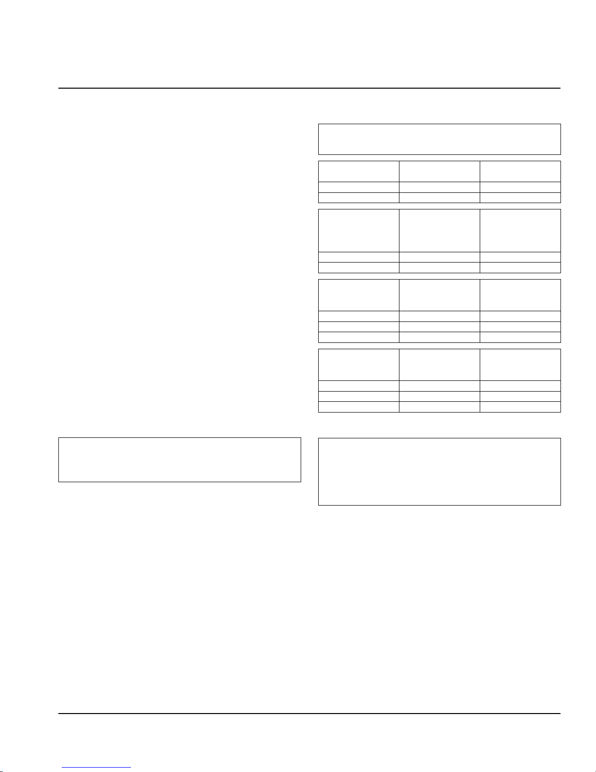
Clearance Requirements
Warning
n
Do not obstruct ice machine vents or openings.
K0250 Self-Contained
Air-Cooled
Top/Sides 12" (30.5 cm) N/A
Back 5" (12.7 cm) N/A
K0350/K0420
K0500/K0600/
K1000/K1350/
K1800
Top/Sides 8" (20.3 cm) 8" (20.3 cm)
Back 5" (12.7 cm) 5" (12.7 cm)
K0420
Tropical Rating
50 Hz Only
Top 24" (61.0 cm) 8" (20.3 cm)
Sides 12" (30.5 cm) 8" (20.3 cm)
Back 5" (12.7 cm) 5" (12.7 cm)
K1000
Tropical Rating
50 Hz Only
Top 12" (30.5 cm) 8" (20.3 cm)
Sides 8" (20.3 cm) 8" (20.3 cm)
Back 5" (12.7 cm) 5" (12.7 cm)
Self-Contained
Air-Cooled
Self-Contained
Air-Cooled
Self-Contained
Air-Cooled
Self-Contained
Water-Cooled
Water-Cooled
and Remote*
Water-Cooled
Water-Cooled
and Remote
Warning
n
Two or more people or a lifting device are required to lift
this appliance.
The ice machine must be protected if it will be subjected
to temperatures below 32°F (0°C). Failure caused by
Caution
,
exposure to freezing temperatures is not covered by the
warranty.
Part Number 000012545 Rev 02 11/16 9
Page 10
Installation Section 2
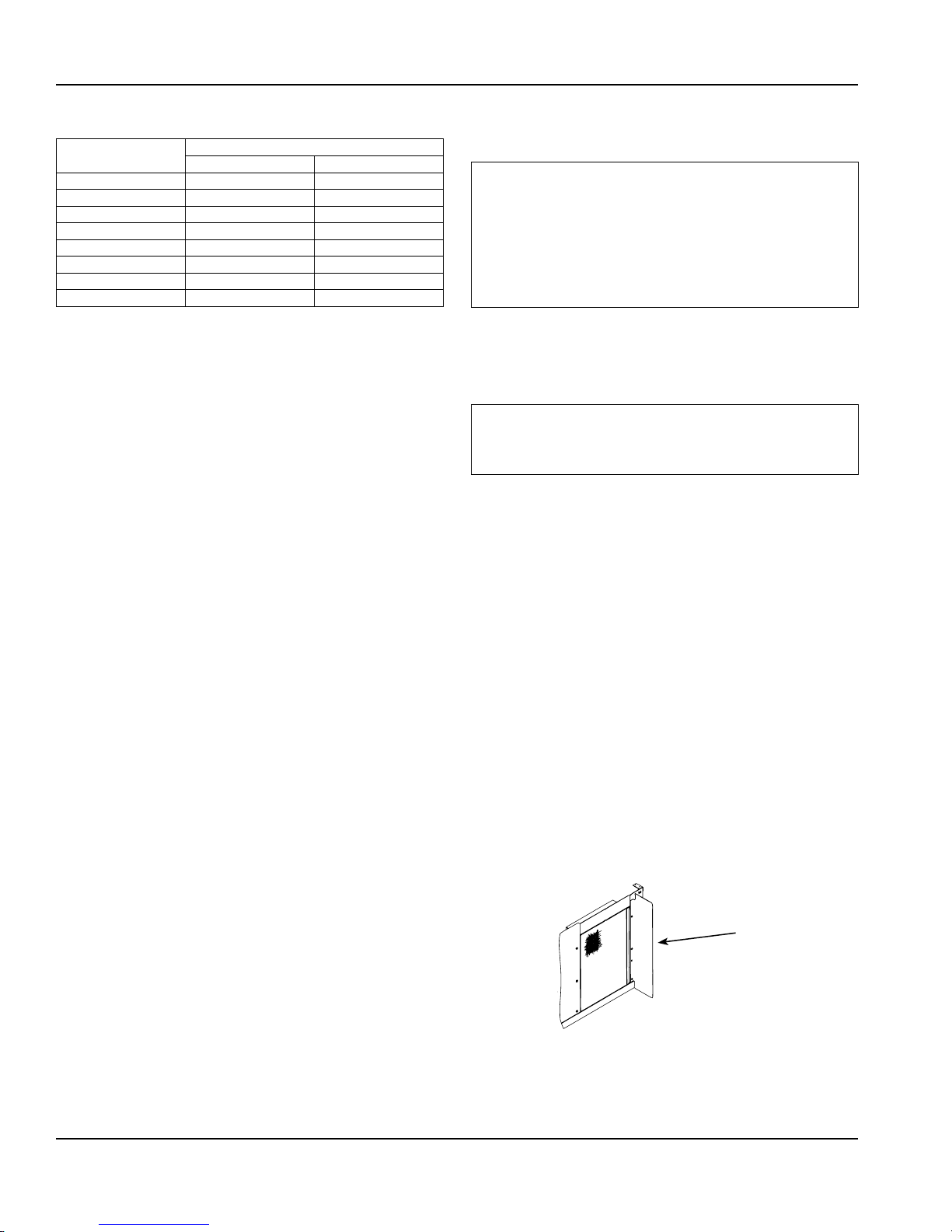
Ice Machine Heat of Rejection
Series
Ice Machine
K0250 4600 5450
K0350 3800 6000
K0420 5400 6300
K0500 5300 6100
K0600 9000 13900
K1000 17000 20700
K1350 23900 29000
K1800 29800 34700
1 B.T.U./Hour
2 Because the heat of rejection varies during the ice making cycle, the
figure shown is an average.
Air Conditioning
Heat of Rejection
2
Ice machines, like other refrigeration equipment, reject
heat through the condenser. It is helpful to know the
amount of heat rejected by the ice machine when sizing air
conditioning equipment where self-contained air-cooled
ice machines are installed.
This information is also necessary when evaluating the
benefits of using water-cooled or remote condensers to
reduce air conditioning loads. The amount of heat added to
an air conditioned environment by an ice machine using a
water-cooled or remote condenser is negligible.
Knowing the amount of heat rejected is also important
when sizing a cooling tower for a water-cooled condenser.
Use the peak figure for sizing the cooling tower.
1
Peak
Removing Drain Plug and Leveling the Ice
Storage Bin
Warning
n
To avoid instability, the bin/dispenser must be installed
in an area capable of supporting the weight of the bin/
dispenser, ice machine and a full bin of ice (48" models
1000 lbs [454 kg], 30" models 750 lbs [340 kg]). The bin/
dispenser must be level side-to-side and front-to-back
before installing the ice machine.
1. Remove threaded plug from drain fitting.
2. Screw the leveling legs onto the bottom of the bin.
3. Screw the foot of each leg in as far as possible.
Caution
,
The legs must be screwed in tightly to prevent them
from bending.
4. Move the bin into its final position.
5. Level the bin to assure that the bin door closes and
seals and the ice machine operates properly. Use a
level on top of the bin. Turn the base of each foot as
necessary to level the bin.
6. Inspect bin gasket prior to ice machine installation.
(Our bins come with a closed cell foam gasket installed
along the top surface of the bin.)
7. Remove all panels from ice machine before lifting and
installing on bin. Remove front panel, top cover, left
and right side panels.
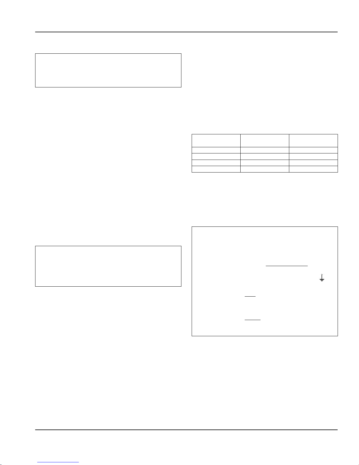
Air Baffle
Self-Contained Air-Cooled Only
To install:
1. Loosen the back panel screws next to the condenser.
2. Align the keyhole slots in the air baffle with the screw
holes and slide the baffle down to lock in place.
Air Baffle
10 Part Number 000012545 Rev 02 11/16
Page 11
Section 2 Installation
Electrical Service
Warning
n
All electrical work, including wire routing and grounding
must conform to all applicable national and local
electrical codes.
MINIMUM CIRCUIT AMPACITY
The minimum circuit ampacity is used to help select the
wire size of the electrical supply. (Minimum circuit ampacity
is not the ice machine’s running amp load.)
ELECTRICAL REQUIREMENTS
Refer to Ice Machine Model/Serial Plate for voltage/
amperage specifications.
• A separate fuse/circuit breaker must be provided for
each ice machine.
• The wire size (or gauge) is dependent upon location,
materials used, length of run, etc., so it must be
determined by a qualified electrician.
• The ice machine must be grounded. Check all green
ground screws in the control box and verify they are
tight before starting the ice machine.
• The maximum allowable voltage variation is ±10% of
the rated voltage at ice machine start-up (when the
electrical load is highest).
Caution
,
Observe correct polarity of incoming line voltage.
Incorrect polarity can lead to erratic ice machine
operation. Operate equipment only on the type of
electricity indicated on the specification plate.
GROUND FAULT CIRCUIT INTERRUPTER
Ground Fault Circuit Interrupter (GFCI/GFI) protection is a
system that shuts down the electric circuit (opens it) when
it senses an unexpected loss of power, presumably to
ground. GFCI/GFI circuit protection is not recommended
with our equipment. If code requires the use of a GFCI/GFI,
then you must follow the local code. The circuit must be
dedicated, sized properly and there must be a panel GFCI/
GFI breaker. We do not recommend GFCI/GFI outlets as they
are known for more intermittent nuisance trips than panel
breakers.
MINIMUM POWER CORD SPECIFICATIONS
Maximum Breaker
Size
15 amp 14 gauge 6 feet (1.83 m)
20 amp 12 gauge 6 feet (1.83 m)
30 amp 10 gauge 6 feet (1.83 m)
40 amp 8 gauge 6 feet (1.83 m)
Minimum Wire
Size
Maximum Length
of Power Cord
If a power cord is used, the wire size to the receptacle is
dependent upon location, materials used, length of run,
etc., so it must be determined by a qualified electrician.
Local, state or national requirements will supersede our
minimum requirements.
FOR UNITED KINGDOM ONLY
As the colors of the wires in the mains lead of the
appliance may not correspond with the colored markings
identifying the terminals in your plug, proceed as follows:
• The wire which is colored green and yellow must be
connected to the terminal in the plug which is marked
with the letter E or by the earth ground symbol or
colored green or green and yellow.
• The wire colored blue must be connected to the
terminal which is marked with the letter N or colored
black.
• The wire colored brown must be connected to the
terminal which is marked with the letter L or colored
red.
Part Number 000012545 Rev 02 11/16 11
Page 12
Installation Section 2
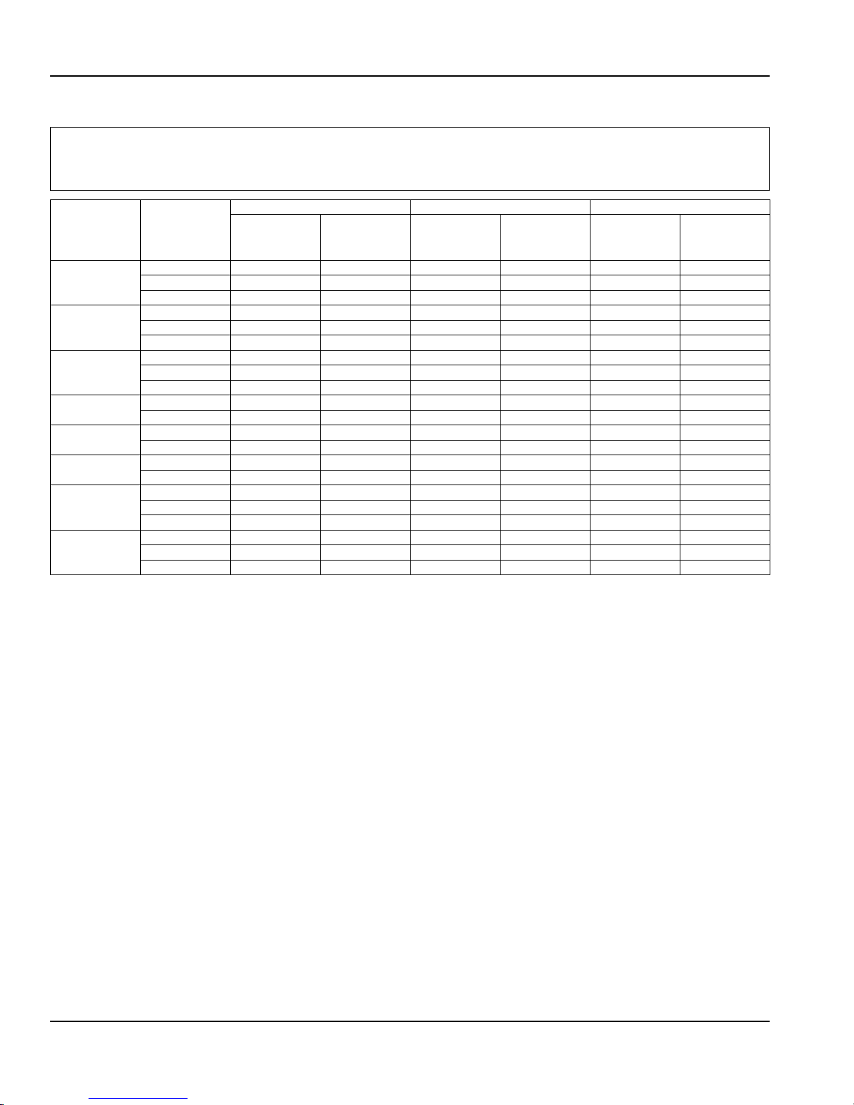
Maximum Breaker Size & Minimum Circuit Amperage Chart
Important
Due to continuous improvements, this information is for reference only. Please refer to the ice machine serial number tag
to verify electrical data. Serial tag information overrides information listed on this page.
Air-Cooled Water-Cooled Remote
Ice Machine
K0250
K0350
K0420
K0500
K0600
K1000
K1350
K1800
Voltage/
Phase/Cycle
115/1/60 15 9.44 N/A N/A N/A N/A
230/1/50 15 4.5 N/A N/A N/A N/A
230/1/60 15 4.7 N/A N/A N/A N/A
115/1/60 15 12.1 15 11.4 N/A N/A
230/1/50 15 6.3 15 5.9 N/A N/A
230/1/60 15 6.2 15 5.8 N/A N/A
115/1/60 15 11.3 15 10.6 N/A N/A
230/1/50 15 6.2 15 5.8 N/A N/A
230/1/60 15 6.2 15 5.8 N/A N/A
115/1/60 20 12.7 20 12.0 N/A N/A
230/1/50 15 6.3 15 5.9 N/A N/A
208-230/1/60 20 9.2 20 8.8 N/A N/A
230/1/50 20 8.6 20 8.2 N/A N/A
208-230/1/60 20 13.9 20 13.2 20 12.8
230/1/50 20 13.8 20 13.1 20 14.1
208-230/1/60 30 18.2 30 16.8 30 17.8
208-230/3/60 20 13.6 20 12.2 20 13.2
230/1/50 30 18.2 30 16.8 30 17.8
208-230/1/60 30 19.6 N/A N/A 30 19.6
208-230/3/60 20 13.3 N/A N/A 20 12.9
230/1/50 30 19.6 N/A N/A 30 19.6
Maximum
Fuse/Circuit
Breaker
Minimum
Circuit Amps
Maximum
Fuse/Circuit
Breaker
Minimum
Circuit Amps
Maximum
Fuse/Circuit
Breaker
Minimum
Circuit Amps
12 Part Number 000012545 Rev 02 11/16
Page 13
Section 2 Installation
Water Supply and Drain Requirements
WATER SUPPLY
Local water conditions may require treatment of the water
to inhibit scale formation, filter sediment, and remove
chlorine odor and taste.
Warning
n
Connect to a potable water supply only. Plumbing must
conform to state, local and national codes.
WATER INLET LINES
Follow these guidelines to install water inlet lines:
• If you are installing a water filter system, refer to the
installation instructions supplied with the filter system
for ice making water inlet connections.
• Do not connect the ice machine to a hot water supply.
Be sure all hot water restrictors installed for other
equipment are working. (Check valves on sink faucets,
dishwashers, etc.)
• If water pressure exceeds the maximum recommended
pressure of 80 psi (552 kPa), obtain a water pressure
regulator from your local distributor.
• Install a water shut-off valve for both the ice making and
condenser water lines.
• Insulate water inlet lines to prevent condensation.
DRAIN CONNECTIONS
Follow these guidelines when installing drain lines to
prevent drain water from flowing back into the ice machine
and storage bin:
• Drain lines must have a 1.5 inch drop per 5 feet of run
(2.5 cm per meter), and must not create traps.
• The floor drain must be large enough to accommodate
drainage from all drains.
• Run separate bin and ice machine drain lines. Insulate
them to prevent condensation.
• Vent the bin and ice machine drain to the atmosphere.
Do not vent the condenser drain on water-cooled
models.
• A separate auxiliary drain is located in the ice machine
base to remove moisture in high humidity areas. The
drain fitting is a female socket for 1/2" CPVC pipe. The
drain is sealed and the seal must be removed before
attaching the drain fitting/tubing. Tap the seal out with
a wooden dowel or similar tool. Seal the CPVC pipe to
the ice machine socket with silicone sealant to allow
future removal.
Caution
,
Do not apply heat to water valve inlet fitting. This will
damage plastic water inlet connection.
Part Number 000012545 Rev 02 11/16 13
Page 14
Installation Section 2
Water Supply and Drain Line Sizing/Connections
Location Water Temperature Water Pressure Ice Machine Fitting
Ice Making Water
Inlet
Ice Making Water
Drain
Condenser Water
Inlet
Condenser Water
Drain
Bin Drain
Large Capacity
Bin Drain
WATERCOOLED CONDENSER WATER PRESSURE
Water pressure at the condenser cannot exceed 150 psig
(1034 kPa) with the standard water-regulating valve.
Contact your distributor if your water pressure is greater
than 150 psig (1034 kPa). A special order condenser/waterregulating valve is available that allows water pressure up
to 350 psig (2413 kPa).
The Commonwealth of Massachusetts requires that
all water-cooled models must be connected only to a
closed loop, cooling tower system.
35°F (2°C) Min.
90°F (32°C) Max.
– – 1/2" (1.27 cm) Female Pipe Thread 1/2" (1.27 cm) min. inside
90°F (32°C) Max. Standard
– – 1/2" (1.27 cm) Female Pipe Thread 1/2" (1.27 cm) min. inside
– – 3/4" (1.91 cm) Female Pipe Thread 3/4" (1.91 cm) min. inside
– – 1" (2.54 cm) Male Pipe Thread 1" (2.54 cm) min. inside diameter
20 psi (140 kPa) Min.
80 psi (552 kPa) Max.
20 psi (140 kPa) Min.
150 psi (1034 kPa) Max.
High Pressure Option
20 psi (140 kPa) Min.
350 psi (2410 kPa) Max.
3/8" (.95 cm) Female Pipe Thread 3/8" (.95 cm) min. inside
COOLING TOWER APPLICATIONS WATERCOOLED
MODELS
A water cooling tower installation does not require
modification of the ice machine. The water regulator valve
for the condenser continues to control the refrigeration
discharge pressure.
It is necessary to know the amount of heat rejection and
Important
the pressure drop through the condenser and water valves
(inlet and outlet) when using a cooling tower on an ice
machine.
• Water entering the condenser must not exceed 90°F
(32°C).
• Water flow through the condenser must not exceed 5
gallons (19 liters) per minute.
• Allow for a pressure drop of 7 psi (50 kPa) between the
condenser water inlet and the outlet of the ice machine.
• Water exiting the condenser must not exceed 110°F
(43°C).
Tubing Size Up to Ice Machine
Fitting
diameter
diameter
3/8" Female Pipe Thread
diameter
diameter
14 Part Number 000012545 Rev 02 11/16
Page 15
Section 2 Installation
Remote Condenser/Line Set Installation
Ice Machine
K1000 KC1000
K1350 KC1350
K1800 KC1350
*Line Set Discharge Line Liquid Line
RTK 1/2" (1.27 cm) 5/16" (.79 cm)
RLK 1/2" (1.27 cm) 3/8" (.95 cm)
Air Temperature Around the Condenser
Minimum Maximum
-20°F (-29°C) 120°F (49°C)
Remote systems are only approved and warranted as a
complete new package. Warranty on the refrigeration
system will be void if a new ice machine head section
is connected to pre-existing (used) tubing or remote
condensers.
Remote Single
Circuit Condenser
Important
Line Set*
RTK-20-R410A
RTK-35-R410A
RTK-50-R410A
RLK-20-R410A
RLK-35-R410A
RLK-50-R410A
RLK-20-R410A
RLK-35-R410A
RLK-50-R410A
REMOTE ICE MACHINE REFRIGERANT CHARGE
Each remote ice machine ships from the factory with a
refrigerant charge appropriate for installation with line
sets of up to 50' (15 m). The serial tag on the ice machine
indicates the refrigerant charge.
Additional refrigerant may be required for installations
using line sets between 50' and 100' (15-30 m) long. If
additional refrigerant is required, refer to the chart below
for the correct amount to be added.
Ice Machine
K1000 2 lbs (907g)
K1350 2 lbs (907g)
K1800 2 lbs (907g)
Refrigerant to be added for
50'-100' Line Sets
Important
EPA CERTIFIED TECHNICIANS
If remote line set length is between 50' and 100'
(15 and 30 m), add additional refrigerant to the
nameplate charge. Refer to the table below for the
model being worked on.
Tubing length: _________________________________
Refrigerant added to nameplate: __________________
New total refrigerant charge: _____________________
Warning
n
Potential Personal Injury Situation
The ice machine contains refrigerant charge. Installation
of the line sets must be performed by a properly trained
and EPA certified refrigeration technician aware of
the dangers of dealing with refrigerant charged
equipment.
Part Number 000012545 Rev 02 11/16 15
Page 16
Installation Section 2
GENERAL
Condensers must be mounted horizontally with the fan
motor on top with nothing obstructing it. There must be at
least a 16" (41 cm) clearance from the bottom for air intake.
The front coupling panel and one other panel (back or side)
must also be unobstructed.
Remote condenser installations consist of vertical and
horizontal line sets between the ice machine and the
condenser. When combined, they must fit within approved
specifications. The following guidelines, drawings and
calculation methods must be followed to verify a proper
remote condenser installation.
Caution
,
The compressor warranty (including the labor
replacement warranty) will not apply if the remote ice
machine is not installed according to specifications.
The warranty also will not apply if the refrigeration
system is modified with a condenser, heat reclaim
device, or other parts or assemblies not manufactured
by us unless we specifically approved the component in
writing.
3
2
1
DOWNWARD
DOWNWARD
HORIZONTAL
HORIZONTAL
SPIRAL
SPIRAL
1
2
3
WIRING
Interconnecting line voltage wiring is used to energize and
de-energize the condenser fan motor.
• The remote condenser voltage matches the ice machine
head section voltage.
Interconnecting Wire Connections
Ice Machine Head Section Remote Condenser
F1 L1
F2 L2
GUIDELINES FOR ROUTING LINE SETS
First, cut a 2.5" (6.35 cm) circular hole in the wall or roof
for tubing routing. The line set end with the 90° bend will
connect to the ice machine. The straight end will connect to
the remote condenser.
Follow these guidelines when routing the refrigerant lines.
This will help ensure proper performance and service
accessibility.
1. Optional - Make the service loop in the line sets (as
shown in Routing Line Sets graphic). This permits easy
access to the ice machine for cleaning and service. Do
not use hard rigid copper at this location.
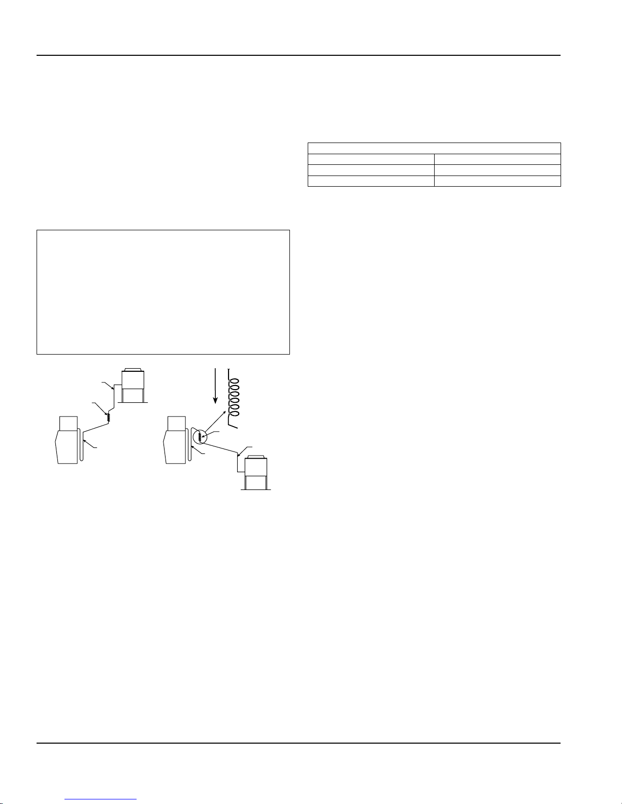
2. Required - Do not form traps in the refrigeration lines
(except the service loop). Refrigerant oil must be free to
drain toward the ice machine or the condenser. Route
excess tubing in a supported downward horizontal
spiral (as shown below). Do not coil tubing vertically.
3. Required - Keep outdoor refrigerant line runs as short
as possible.
Routing Line Sets
16 Part Number 000012545 Rev 02 11/16
Page 17
Section 2 Installation
H
H
H
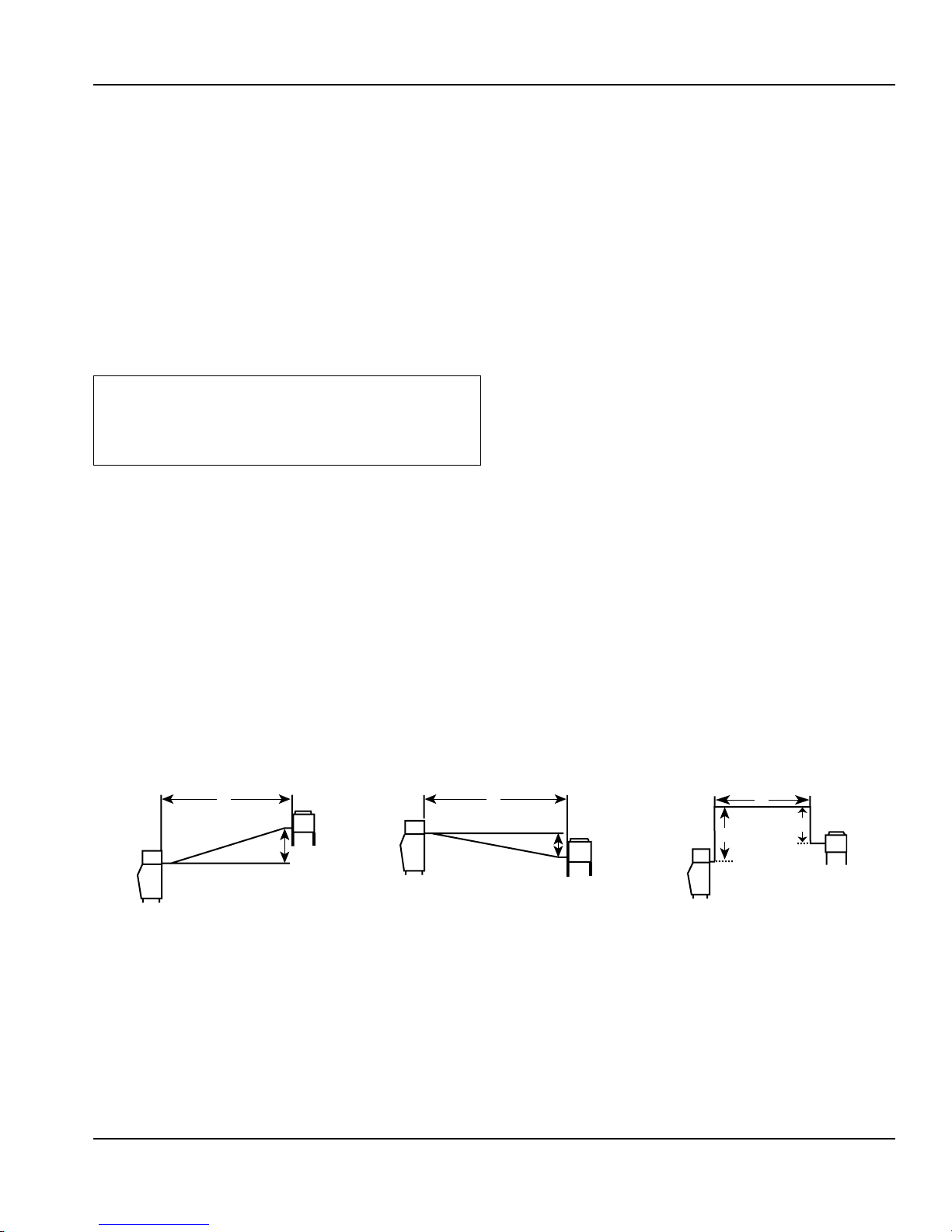
CALCULATING REMOTE CONDENSER INSTALLATION
DISTANCES
Line Set Length
The maximum length is 100' (30 m).
The ice machine compressor must have the proper oil
return. The receiver is designed to hold a charge sufficient
to operate the ice machine in ambient temperatures
between -20°F (-29°C) and 120°F (49°C), with line set
lengths of up to 100' (30 m).
Line Set Rise/Drop
The maximum rise is 35' (10.7 m).
The maximum drop is 15' (4.5 m).
Caution
,
If a line set has a rise followed by a drop, another
rise cannot be made. Likewise, if a line set has a drop
followed by a rise, another drop cannot be made.
Calculated Line Set Distance
The maximum calculated distance is 150' (45 m).
Line set rises, drops, horizontal runs (or combinations
of these) in excess of the stated maximums will exceed
compressor start-up and design limits. This will cause poor
oil return to the compressor.
Make the following calculations to make sure the line set
layout is within specifications.
1. Insert the measured rise into the formula below.
Multiply by 1.7 to get the calculated rise.
(Example: A condenser located 10 feet above the ice
machine has a calculated rise of 17 feet.)
2. Insert the measured drop into the formula below.
Multiply by 6.6 to get the calculated drop.
(Example. A condenser located 10 feet below the ice
machine has a calculated drop of 66 feet.)
3. Insert the measured horizontal distance into the
formula below. No calculation is necessary.
4. Add together the calculated rise, calculated drop,
and horizontal distance to get the total calculated
distance. If this total exceeds 150' (45 m), move
the condenser to a new location and perform the
calculations again.
Maximum Line Set Distance Formula
Step 1. Measured Rise (35' [10.7 m] Maximum) ______ x 1.7 = _______ Calculated Rise
Step 2. Measured Drop (15' [4.5 m] Maximum) ______ x 6.6 = _______ Calculated Drop
Step 3. Measured Horizontal Distance (100' [30 m] Maximum) _______ Horizontal Distance
Step 4. Total Calculated Distance 150' (45 m) _______ Total Calculated Distance
D
R
SV1196 SV1195 SV1194
Combination of a Rise and a
HorizontalRun
D
Combination of a Drop and a
HorizontalRun
R
Combination of a Rise, a Drop and a
Horizontal Run
Part Number 000012545 Rev 02 11/16 17
Page 18

Installation Section 2
ROUTE THE LINE SET
• Route the line set to avoid traps and kinks.
• Minimize the amount of line set exposed on the roof.
CONNECT THE LINE SET
• Cut the line set to the correct length.
• Purge line set with dry nitrogen while brazing.
• Line set shutoff valves on the ice machine must remain
closed and be protected from heat during brazing.
PRESSURE TEST AND EVACUATE LINE SET AND
CONDENSER
• Lineset shutoff valves must remain closed until pressure
testing and evacuation are complete.
• Pressure test @ 150 psi (1000 kPa) for a minimum of 15
minutes.
• Minimum evacuation level is 500 microns.
• Pressure test the line set and condenser with 150 psig of
dry nitrogen. Add nitrogen at the line set shutoff valves
located at the back of the ice machine head section.
Complete the pressure test, verify no leaks are present
and remove the nitrogen from the system before
connecting the vacuum pump.
OPEN LINE SET VALVES
You will not hear refrigerant flow when the valves are
opened. Refrigerant will not flow until the ice machine is
started and the solenoid valve opens.
• All valve caps must be reinstalled, tightened and leakchecked to assure no refrigerant leakage exists.
• Counterclockwise opens all valves.
18 Part Number 000012545 Rev 02 11/16
Page 19
Section 2 Installation
Installation Check List
Is the Ice Machine level?
Have all of the electrical and water connections
beenmade?
Has the supply voltage been tested and checked
against the rating on the nameplate?
Is there proper clearance around the ice machine forair
circulation?
Is the ice machine grounded and polarity correct?
Has the ice machine been installed where ambient
temperatures will remain in the range of 35° - 110°F
(1.6° - 43.3°C)?
Has the ice machine been installed where the incoming
water temperature will remain in the rangeof 35° - 90°F
(1.6° - 32.2°C)?
Is there a separate drain for the potable water,
binandwater-cooled condenser?
Additional Checks for Remote Models
Does the remote condenser fan operate properly
afterstart-up?
Has the remote condenser been located where
ambient temperatures will remain in the range of -20°120°F (-29 - 49°C).
Is the line set routed properly?
Are both refrigeration lines to remote condenser run so
they do not lay in water and are properly insulated?
Before Starting the Ice Machine
All ice machines are factory-operated and adjusted before
shipment. Normally, new installations do not require any
adjustment.
To ensure proper operation, follow the Operational Checks
in Section 3 of this manual. Starting the ice machine and
completing the Operational Checks are the responsibilities
of the owner/operator.
Adjustments and maintenance procedures outlined in this
manual are not covered by the warranty.
Are the ice machine and bin drains vented?
Are all refrigerant lines free from contact with
othercomponents?
Are all electrical leads free from contact with
refrigeration lines and moving equipment?
Has the owner/operator been instructed
regardingmaintenance and the use of our Cleanerand
Sanitizer?
Has the owner/operator completed the
warrantyregistration card?
Has the ice machine and bin been sanitized?
Is the ice thickness set correctly? (Refer to
OperationalChecks to check/set the correct ice
bridgethickness).
Warning
n
Potential Personal Injury Situation
Do not operate equipment that has been misused,
abused, neglected, damaged, or altered/modified from
that of original manufactured specifications.
Part Number 000012545 Rev 02 11/16 19
Page 20

Installation Section 2
THIS PAGE INTENTIONALLY LEFT BLANK
20 Part Number 000012545 Rev 02 11/16
Page 21

Section 3
Operation
Ice Making Sequence of Operation
NOTE: The toggle switch must be in the ICE position and the
water curtain must be closed before the ice machine will
start.
Water Purge Cycle
The ice machine purges any remaining water from the
water trough down the drain and the refrigeration
compressor starts.
Freeze Cycle
Prechill - The refrigeration system chills the evaporator
before water flow over the evaporator starts. The water inlet
valve energizes during the pre-chill and remains on until
the Ice Thickness Float Switch is satisfied.
Freeze - Water flowing across the evaporator freezes and
builds ice on the evaporator. After a sheet of ice has formed,
the Harvest Float Switch signals the control board to start a
harvest cycle.
Harvest Cycle
Any remaining water is purged down the drain as
refrigerant gas warms the evaporator. When the evaporator
warms, the sheet of cubes slides off the evaporator and into
the storage bin. If all cubes fall clear of the water curtain,
the ice machine starts another freeze cycle.
Full Bin Cycle
If the water curtain is held open by ice cubes, the ice
machine shuts off and starts a 3-minute delay period. When
the water curtain closes, the ice machine starts a new cycle
at the water purge, provided the 3-minute delay period has
expired.
CONTROL BOARD TIMERS
The control board has the following non-adjustable timers:
• The ice machine is locked into the freeze cycle for 6
minutes before a harvest cycle can be initiated.
• The maximum freeze time is 60 minutes, at which time
the control board automatically initiates a harvest
sequence.
• The maximum harvest time is 3.5 minutes. The control
board automatically initiates a freeze sequence when
these times are exceeded.
SAFETY LIMITS
Safety limits are stored and indicated by the control board.
The number of cycles required to stop the ice machine
varies for each safety limit.
Safety limits can be reset by pressing the On/Off button and
starting a new ice making cycle.
A safety limit is indicated by a flashing Service Light on the
control board.
• Safety Limit 1 - If the freeze time reaches 60 minutes,
the control board automatically initiates a harvest cycle.
If 6 consecutive 60-minute freeze cycles occur, the ice
machine stops.
• Safety Limit 2 - If the harvest time reaches 3.5 minutes,
the control board automatically returns the ice machine
to the freeze cycle. If 500 consecutive 3.5 minute harvest
cycles occur, the ice machine stops.
• Safety Limit 3 - If the freeze time reaches 4 minutes
and water is not sensed, the ice machine stops and
initiates a 30 minute delay period. The ice machine will
automatically restart at the end of the 30 minute delay
period. If 100 consecutive failures occur, the ice machine
stops.
Part Number 000012545 Rev 02 11/16 21
Page 22

Operation Section 3
Operational Checks
GENERAL
All ice machines are factory-operated and adjusted before
shipment. Normally, new installations do not require any
adjustment.
To ensure proper operation, always follow the Operational
Checks:
• when starting the ice machine for the first time
• after a prolonged out-of-service period
• after cleaning and sanitizing
NOTE: Routine adjustments and maintenance procedures
are not covered by the warranty.
MINIMUM/MAXIMUM SLAB WEIGHTS
Adjust ice thickness to meet chart specifications.
Model Minimum Ice Weight
Per Cycle
K0250 3.4 lbs
1542 g
K0350 3.4 lbs
1542 g
K420 3.4 lbs
1542 g
K0500 4.125 lbs
1871 g
K0600 4.125 lbs
1871 g
K1000 7.25 lbs
3288 g
K1350 12.8 lbs
5805 g
K1800 12.8 lbs
5805 g
Maximum Ice Weight
Per Cycle
3.9 lbs
1769 g
3.9 lbs
1769 g
3.9 lbs
1769 g
4.75 lbs
2154 g
4.75 lbs
2154 g
7.75 lbs
3515 g
14.4 lbs
6532 g
14.4 lbs
6532 g
ICE THICKNESS CHECK
After a harvest cycle, inspect the ice cubes in the ice storage
bin. The ice thickness float switch is factory-set to maintain
the ice bridge thickness at 1/8" (3 mm).
NOTE: Make sure the water curtain is in place when
performing this check. It prevents water from splashing out
of the water trough.
1. Inspect the bridge connecting the cubes. It should be
about 1/8" (3 mm) thick.
2. If adjustment is necessary, turn the ice thickness
float switch clockwise to increase bridge thickness,
counterclockwise to decrease bridge thickness. Adjust
to achieve a 1/8" (3 mm) bridge thickness.
NOTE: The float can be adjusted with a 3/4" wrench while
the water trough is in place. Test run two cycles to verify
water level.
Ice Thickness Float
Switch Adjustment
22 Part Number 000012545 Rev 02 11/16
Page 23

Section 4
Maintenance
Cleaning and Sanitizing
GENERAL
You are responsible for maintaining the ice machine
in accordance with the instructions in this manual.
Maintenance procedures are not covered by the warranty.
Clean and sanitize the ice machine every six months
for efficient operation. If the ice machine requires more
frequent cleaning and sanitizing, consult a qualified
service company to test the water quality and recommend
appropriate water treatment. An extremely dirty ice
machine must be taken apart for cleaning and sanitizing.
Manitowoc Ice Machine Cleaner and Sanitizer are the only
products approved for use in this ice machine.
Caution
,
Use only approved Ice Machine Cleaner and Sanitizer
for this application (Manitowoc Cleaner part number
9405463 and Manitowoc Sanitizer part number
9405653). It is a violation of Federal law to use these
solutions in a manner inconsistent with their labeling.
Read and understand all labels printed on bottles before
use.
Caution
,
Do not mix Cleaner and Sanitizer solutions together. It
is a violation of Federal law to use these solutions in a
manner inconsistent with their labeling.
Warning
n
Wear rubber gloves and safety goggles (and/or face
shield) when handling Ice Machine Cleaner or Sanitizer.
CLEANING/SANITIZING PROCEDURE
This procedure must be performed a minimum of once
every six months.
• The ice machine and bin must be disassembled, cleaned
and sanitized.
• All ice produced during the cleaning and sanitizing
procedures must be discarded.
• Removes mineral deposits from areas or surfaces that
are in direct contact with water.
PREVENTATIVE MAINTENANCE CLEANING PROCEDURE
• This procedure cleans all components in the water flow
path, and is used to clean the ice machine between
the bi-yearly cleaning/sanitizing procedure without
removing the ice from the bin/dispenser.
• This technology will also allow initiation and completion
of a clean or sanitize cycle, after which the ice machine
automatically starts ice making again.
EXTERIOR CLEANING
Clean the area around the ice machine as often as necessary
to maintain cleanliness and efficient operation.
Wipe surfaces with a damp cloth rinsed in water to remove
dust and dirt from the outside of the ice machine. If a greasy
residue persists, use a damp cloth rinsed in a mild dish soap
and water solution. Wipe dry with a clean, soft cloth.
The exterior panels have a clear coating that is stain
resistant and easy to clean. Products containing abrasives
will damage the coating and scratch the panels.
• Never use steel wool or abrasive pads for cleaning.
• Never use chlorinated, citrus-based or abrasive cleaners
on exterior panels and plastic trim pieces.
Part Number 000012545 Rev 02 11/16 23
Page 24

Maintenance Section 4
Cleaning/Sanitizing Procedure
Caution
,
Use only approved Ice Machine Cleaner and Sanitizer for
this application (Manitowoc Cleaner part number 940546-3 and Manitowoc Sanitizer part number 94-0565-
3). It is a violation of Federal law to use these solutions
in a manner inconsistent with their labeling. Read and
understand all labels printed on bottles before use.
Caution
,
Do not mix Cleaner and Sanitizer solutions together. It
is a violation of Federal law to use these solutions in a
manner inconsistent with their labeling.
Warning
n
Wear rubber gloves and safety goggles (and/or face
shield) when handling Ice Machine Cleaner or Sanitizer.
Ice machine cleaner is used to remove lime scale and
mineral deposits. Ice machine sanitizer disinfects and
removes algae and slime.
Step 1 Remove the front door to access the evaporator
compartment. Ice must not be on the evaporator during
the clean/sanitize cycle. Set the toggle switch to the OFF
position after ice falls from the evaporator at the end of a
harvest cycle. Or, set the switch to OFF and allow the ice to
melt off the evaporator(s).
Caution
,
Never use anything to force ice from the evaporator.
Damage may result.
Step 2 Remove all ice from the bin/dispenser.
Step 3 Place the toggle switch in the CLEAN position.
Water will flow through the water dump valve and down
the drain. Wait until the water trough refills, then add the
proper amount of ice machine cleaner.
Model Amount of Cleaner
K0250 K0350 K0420 3 ounces (90 ml)
K0500 K0600 K1000 5 ounces (150 ml)
K1350 K1800 9 ounces (265 ml)
Step 4 Wait until the clean cycle is complete
(approximately 24 minutes). Then disconnect power to the
ice machine (and dispenser when used).
Warning
n
Disconnect the electric power to the ice machine at the
electric service switch box.
Step 5 Remove parts for cleaning.
Please refer to the proper parts removal for your ice
machine. Continue with step 6 when the parts have
been removed.
Single Evaporator Ice Machines - page 26
24 Part Number 000012545 Rev 02 11/16
Page 25

Section 4 Maintenance
Step 6 Mix a solution of cleaner and lukewarm water.
Depending upon the amount of mineral buildup, a larger
quantity of solution may be required. Use the ratio in the
table below to mix enough solution to thoroughly clean all
parts.
Solution Type Water Mixed with
Cleaner 1 gal. (4 L) 16 oz (500 ml) cleaner
Step 7 Use 1/2 of the cleaner/water mixture to clean
all components. The cleaner solution will foam when it
contacts lime scale and mineral deposits; once the foaming
stops use a soft-bristle nylon brush, sponge or cloth (NOT
a wire brush) to carefully clean the parts. Soak parts for
5 minutes (15-20 minutes when heavily scaled). Rinse all
components with clean water.
Step 8 While components are soaking, use 1/2 of the
cleaner/water solution to clean all foodzone surfaces of the
ice machine and bin (or dispenser). Use a nylon brush or
cloth to thoroughly clean the following ice machine areas:
• Evaporator plastic parts – including top, bottom and
sides
• Bin bottom, sides and top
Rinse all areas thoroughly with clean water.
SANITIZING PROCEDURE
Step 9 Mix a solution of sanitizer and lukewarm water.
Solution Type Water Mixed with
Sanitizer 3 gal. (12 L) 2 oz (60 ml) sanitizer
Step 10 Use 1/2 of the sanitizer/water solution to sanitize
all removed components. Use a spray bottle to liberally
apply the solution to all surfaces of the removed parts or
soak the removed parts in the sanitizer/water solution. Do
not rinse parts after sanitizing.
Step 11 Use 1/2 of the sanitizer/water solution to sanitize
all foodzone surfaces of the ice machine and bin (or
dispenser). Use a spray bottle to liberally apply the solution.
When sanitizing, pay particular attention to the following
areas:
• Evaporator plastic parts - including top, bottom and
sides
• Ice machine base (top of bin) and area above the water
trough
• Bin sides and bottom
Do not rinse the sanitized areas.
Step 12 Replace all removed components.
Step 13 Wait 25 minutes.
Step 14 Reapply power to the ice machine and place the
toggle switch in the CLEAN position.
Step 15 Wait until the water trough refills, then add the
proper amount of Manitowoc Ice Machine Sanitizer to the
water trough.
Model Amount of Sanitizer
K0250 K0350 K0420
K0500 K0600 K1000
K1350 K1800 6 ounces (180 ml)
3 ounces (90 ml)
Step 16 After the sanitize cycle is complete (approximately
24 minutes) move the toggle switch to the ICE position to
start ice making.
Part Number 000012545 Rev 02 11/16 25
Page 26

Maintenance Section 4
Parts Removal for Cleaning/Sanitizing
Single Evaporator Ice Machines
A. Remove the water curtain
• Gently flex the curtain in the center and remove it from
the right side.
• Slide the left pin out.
B. Remove the water trough
• Depress tabs on right and left side of the water trough.
• Allow front of water trough to drop as you pull forward
to disengage the rear pins.
C. Remove the ice thickness and harvest float switches
• Pull the float switch straight down to disengage.
• Lower the float switch until the wiring connector is
visible.
• Disconnect the wire lead from the float switch.
• Remove the float switch from the ice machine.
D. Remove the water distribution tube
NOTE: Distribution tube thumbscrews are retained
to prevent loss. Loosen thumbscrews but do not pull
thumbscrews out of distribution tube.
• Loosen the two outer screws (do not remove screws
completely they are retained to prevent loss) and pull
forward on the distribution tube to release from slip
joint.
• Disassemble distribution tube by loosening the two (2)
middle thumbscrews and dividing the distribution tube
into two pieces.
• Proceed to page 25 Step 6.
D
C
A
B
26 Part Number 000012545 Rev 02 11/16
Page 27

Section 4 Maintenance
Preventative Maintenance Cleaning Procedure
This procedure cleans all components in the water flow
path, and is used to clean the ice machine between the biyearly cleaning/sanitizing procedure.
Ice machine cleaner is used to remove lime scale and
mineral deposits. Ice machine sanitizer disinfects and
removes algae and slime.
NOTE: Although not required and dependent on your
installation, removing the ice machine top cover may allow
easier access.
Step 1 Ice must not be on the evaporator during the
clean/sanitize cycle. Follow one of the methods below:
• Move the toggle switch to the OFF position at the end
of a harvest cycle after ice falls from the evaporator(s).
• Move the toggle switch to the OFF position and allow
the ice to melt.
Caution
,
Never use anything to force ice from the evaporator.
Damage may result.
Step 2 Open the front door and move the toggle switch
to the CLEAN position. Wait until the water trough refills
(approximately 1 minute) and then add the proper amount
of Ice Machine Cleaner to the water trough.
Model Amount of Cleaner
K0250 K0350 K0420 3 ounces (90 ml)
K0500 K0600 K1000 5 ounces (150 ml)
K1350 K1800 9 ounces (265 ml)
Step 3 After 1 minute place the toggle switch in the
ICE position and close and secure the front door. The ice
machine will automatically start ice making after the Clean
cycle is complete (approximately 24 minutes).
Door Removal
1. Use a Phillips screwdriver to loosen the two screws
securing the door. Do not remove, they are retained to
prevent loss.
2. Tilt door forward and lift up to remove.
Cleaning the Condenser Filter
The washable filter on self-contained ice machines is
designed to catch dust, dirt, lint and grease. Clean the filter
with a mild soap and water.
Cleaning the Condenser
Warning
n
Disconnect electric power to the ice machine head
section and the remote condensing unit at the electric
service switches before cleaning the condenser.
A dirty condenser restricts airflow, resulting in excessively
high operating temperatures. This reduces ice production
and shortens component life.
• Clean the condenser at least every six months.
Warning
n
The condenser fins are sharp. Use care when cleaning
them.
• Shine a flashlight through the condenser to check for
dirt between the fins.
• Blow compressed air or rinse with water from the inside
out (opposite direction of airflow).
• If dirt still remains call a service agent to clean the
condenser.
Part Number 000012545 Rev 02 11/16 27
Page 28

Maintenance Section 4
Removal from Service/Winterization
1. Clean and sanitize the ice machine.
2. Move the toggle switch to the OFF position and turn off
the ice machine.
3. Turn off the water supply, disconnect and drain the
incoming ice-making water line at the rear of the ice
machine and drain the water trough.
4. Energize the ice machine, wait one minute for the
water inlet valve to open and blow compressed air in
both the incoming water and the drain openings in the
rear of the ice machine to remove all water.
5. Move the toggle switch to the OFF position and turn off
the ice machine. Disconnect the electric power at the
circuit breaker or the electric service switch.
6. Fill spray bottle with sanitizer/water solution and spray
all interior food zone surfaces. Do not rinse and allow to
air dry.
7. Replace all panels.
WATERCOOLED ICE MACHINES
1. Perform steps 1-6 under “Removal from Service/
Winterization”.
2. Disconnect the incoming water and drain line from the
water-cooled condenser.
3. Energize the ice machine in the freeze cycle. The
increasing refrigerant pressure will open the water
regulating valve.
4. Blow compressed air through the condenser until no
water remains.
5. Replace all panels.
28 Part Number 000012545 Rev 02 11/16
Page 29

Section 5
Troubleshooting
Checklist
If a problem arises during operation of your ice machine, follow the checklist below before calling service. Routine
adjustments and maintenance procedures are not covered by the warranty.
Problem Possible Cause To Correct
Ice machine does not operate. No electrical power to the ice machine. Replace the fuse/reset the breaker/turn on the
main switch/plug power cord into receptacle.
Ice machine needs to be turned on. Place the toggle switch in the ICE position to
start ice making.
Curtain in open position (down). Curtain must be in the closed position and
capable of swinging freely.
Ice machine stops, and can be restarted
by turning the ice machine OFF and then
ON.
Ice sheet is thick Water trough level is too high. Adjust ice thickness float.
Ice machine does not release ice or is slow
to harvest.
Ice machine does not cycle into harvest
mode.
Ice quality is poor
(soft or not clear).
Ice machine produces shallow or
incomplete cubes, or the ice fill pattern on
the evaporator is incomplete.
Safety limit feature stopping the ice machine. Refer to “Safety Limit Feature” on the next
page.
Power button was turned off/on during freeze
cycle and ice remained on evaporator.
Ice damper was opened then closed in the
harvest cycle before the ice released.
Ice machine is dirty. Clean and sanitize the ice machine.
Ice machine is not level. Level the ice machine.
Low air temperature around ice machine (aircooled models).
Water regulating valve leaks in harvest mode
(water-cooled models).
The six-minute freeze time lock-in has not
expired yet.
Ice thickness float switch is dirty. Clean and sanitize the ice machine.
Ice thickness float switch wire is disconnected. Connect the wire.
Ice thickness float switch is out of adjustment. Adjust the ice thickness float switch.
Uneven ice fill (thin at top of evaporator). See “Shallow or Incomplete Cubes” on the
Poor incoming water quality. Contact a qualified service company to test
Water filtration is poor. Replace the filter.
Ice machine is dirty. Clean and sanitize the ice machine.
Water softener is working improperly (if
applicable).
Ice thickness float switch is out of adjustment. Adjust the ice thickness float switch.
Water trough level is too high or too low. Check the water level and adjust if required.
Water filtration is poor. Replace the filter.
Hot incoming water. Connect the ice machine to a cold water
Incorrect incoming water pressure. Water pressure must be 20-80 psi (137.9 -
Ice machine is not level. Level the ice machine.
Allow ice to thaw and release from evaporator,
then restart.
Allow ice to thaw and release from evaporator,
then restart.
Air temperature must be at least 40°F (4°C).
Replace water regulating valve.
Wait for freeze lock-in to expire.
next page.
the quality of the incoming water and make
appropriate filter recommendations.
Repair the water softener.
supply.
551.5 kPa).
Continued on next page...
Part Number 000012545 Rev 02 11/16 29
Page 30

Troubleshooting Section 5
Problem Possible Cause To Correct
Low ice capacity. The condenser is dirty. Clean the condenser.
High air temperature around ice machine (aircooled models).
Inadequate clearance around the ice machine. Provide adequate clearance.
Objects stacked around ice machine, blocking
airflow to condenser (air-cooled models).
Hot incoming water. Connect the ice machine to a cold water
Incorrect incoming water pressure. Water
pressure is too low or water filter is restricted.
Air temperature must not exceed 110°F (43°C).
Remove items blocking airflow.
supply.
Water pressure must be 20-80 psi (137.9 -
551.5 kPa). Refer to Section 2 for plumbing
requirements. Replace water filter.
Safety Limit Feature
In addition to the standard safety controls, such as the high
pressure cutout, your ice machine features built-in safety
limits which will stop the ice machine if conditions arise
which could cause a major component failure.
Refer to Safety Limits Section 3 for more information on
safety limits.
Before calling for service, re-start the ice machine using the
following procedure:
1. Move the toggle switch to OFF, then the ICE position,
A. If the safety limit feature has stopped the ice
machine, it will restart after a short delay. Proceed
to step 2.
B. If the ice machine does not restart, see “Ice
machine does not operate” on the previous page.
2. Allow the ice machine to run to determine if the
condition repeats.
A. If the ice machine stops again, the condition has
repeated. Call for service.
B. If the ice machine continues to run, the condition
has corrected itself. Allow the ice machine to
continue running.
30 Part Number 000012545 Rev 02 11/16
Page 31

Page 32

Page 33

Avis de sécurité
Avis de sécurité
Lire ces précautions pour éviter des blessures
corporelles:
• Lire attentivement ce manuel avant de faire
fonctionner, d’installer ou de faire un entretien sur
l’équipement. Ne pas suivre les instructions dans
ce manuel peut entraîner des dégâts matériels, des
blessures corporelles, voire même la mort.
• Les réglages de routine et les procédures d’entretien
indiqués dans ce manuel ne sont pas couverts par la
garantie.
• L’installation, le soin et l’entretien sont essentiels pour
un rendement maximal et un fonctionnement sans
problème de votre appareil.
Visitez notre site Web www.manitowocice.com pour
des mises à jour manuelles, des traductions, ou bien
les coordonnées des agents techniques de votre
région.
• Cet appareil est soumis à des tensions électriques et
des charges de fluide frigorigène élevées. L’installation
et les réparations doivent être effectuées par des
techniciens adéquatement formés et conscients des
dangers propres aux tensions électriques élevées et
au liquide frigorigène sous pression. Le technicien
doit également être certifié dans le secteur de la
manipulation appropriée de fluide frigorigène et dans
les procédures d’entretien. Toutes les procédures de
verrouillage et d’étiquetage doivent être suivies lors
d’une intervention sur cet équipement.
• Cet équipement est destiné uniquement à un usage
intérieur. Ne pas installer ou faire fonctionner cet
équipement à l’extérieur.
Avertissement
n
Suivez ces exigences électriques pendant l’installation
de cet équipement.
• Tout le câblage sur site doit être conforme à tous les
codes applicables de l’autorité ayant juridiction. Il
est de la responsabilité de l’utilisateur de fournir les
moyens de déconnexion pour satisfaire les codes
locaux. Se reporter à la plaque signalétique pour la
tension appropriée.
• Cet appareil doit être mis à terre.
• Cet équipement doit être positionné de sorte que la
prise de courant soit accessible à moins qu’un autre
moyen de déconnexion de l’alimentation électrique
(par ex. disjoncteur ou interrupteur général) soit
fourni.
• Vérifier toutes les connexions de câblage, y compris
les bornes d’usine, avant de faire fonctionner. Les
connexions peuvent se desserrer durant l’expédition
et l’installation.
Page 34

Avertissement
n
Suivre ces précautions pour éviter des blessures
corporelles durant l’installation de cet équipement:
• L’installation doit être conforme aux codes d’incendie
et de santé applicables selon l’autorité ayant
juridiction.
• Afin d’éviter toute instabilité, la zone de l’installation
doit être capable de supporter le poids combiné de
l’équipement et du produit. De plus l’équipement
doit être mis à niveau d’un côté à l’autre et d’en avant
à en arrière.
• Les machines à glaçons requièrent un déflecteur
lorsqu’elles sont installées sur un bac de stockage
de glaçons. Avant toute utilisation d’un système de
stockage de glaçons autre que Manitowoc avec cette
machine à glaçons, contacter le fabricant du bac pour
s’assurer de la compatibilité de leur déflecteur de
glaçons.
• Retirer tous les panneaux amovibles avant de
soulever et d’installer; utiliser l’équipement de
sécurité approprié pendant l’installation et l’entretien.
Pour déplacer ou soulever cet appareil et l’empêcher
de basculer ou de causer des blessures, il est
nécessaire de faire appel à au moins deux personnes.
• Ne pas endommager le circuit de réfrigération lors
de l’installation, de l’entretien ou de la réparation de
l’appareil.
• Connecter à une alimentation en eau potable
uniquement.
• Cet équipement contient une charge de fluide
frigorigène. L’installation des conduites doit être
effectuée par un technicien adéquatement formé et
certifié dans le secteur de la réfrigération par l’EPA,
qui est conscient des dangers que comportent les
équipements chargés de fluide frigorigène.
• Les pieds ou les roulettes doivent être installés et les
pieds/roulettes doivent être vissés complètement.
Lorsque des roulettes sont installées, la masse de
cet appareil est suffisante pour que celui-ci puisse
se déplacer de façon incontrôlée sur une surface
inclinée. Ces appareils doivent être attachés/fixés
en conformité avec tous les codes applicables. Les
roulettes orientables doivent être montées à l’avant
et les roulettes fixes doivent être montées à l’arrière.
Verrouiller les roulettes avant une fois l’installation
terminée.
Avertissement
n
Suivre ces précautions pour éviter des blessures
corporelles durant l’installation ou l’entretien de cet
équipement:
• Lire attentivement ce manuel avant de faire
fonctionner, d’installer ou de faire un entretien sur
l’équipement. Ne pas suivre les instructions dans
ce manuel peut entraîner des dégâts matériels, des
blessures corporelles, voire même la mort.
• Risque d’écrasement ou de pincement. Garder les
mains éloignées des composants en mouvement.
Les composants peuvent bouger sans avertissement
à moins que le courant soit déconnecté et que tout
potentiel d’énergie soit éliminé.
• L’humidité qui s’accumule sur le plancher peut créer
une surface glissante. Nettoyer immédiatement toute
eau sur le plancher pour éviter un risque de glisser.
• Les objets placés ou échappés dans le bac peuvent
affecter la santé et la sécurité des personnes. Repérer
et enlever tout objet immédiatement.
• Ne jamais utiliser des objets ou outils tranchants
pour enlever la glace ou le givre. Ne pas utiliser
des dispositifs mécaniques ou autres moyens pour
accélérer le processus de dégivrage.
• Lors de l’utilisation de liquides de nettoyage ou
tout autre produit chimique, porter des gants en
caoutchouc et des lunettes de protection (et/ou écran
facial).
DANGER
Ne pas faire fonctionner un appareil ayant fait l’objet
d’une mauvaise utilisation, ayant été abusé, négligé,
endommagé ou altéré/modifié par rapport aux
caractéristiques d’origine de fabrication. Cet appareil
n’a pas été conçu pour être utilisé par des personnes
(y compris des enfants) aux capacités physiques,
sensorielles ou mentales réduites ou n’ayant pas une
expérience ou des connaissances suffisantes, sauf si
elles sont supervisées par une personne responsable
de leur sécurité. Ne pas laisser les enfants jouer avec,
nettoyer ou entretenir cet appareil sans une surveillance
adéquate.
Warning
n
Ça produire c'est hermétiquement sceller et renfermer
fluorinated serre gaz R410A
Page 35

DANGER
Suivre ces précautions pour éviter des blessures
corporelles durant l’utilisation et l’entretien de cet
équipement:
• Il incombe au propriétaire de l’appareil d’effectuer une
analyse des risques pour déterminer l’équipement de
protection individuel nécessaire et pour s’assurer que
la protection est suffisante pendant les procédures de
maintenance.
• Ne pas stocker ou utiliser de l’essence ou d’autres
vapeurs ou liquides inflammables à proximité de
cet appareil ou de tout autre appareil. Ne jamais
utiliser des linges trempés d’huile inflammable ou
de solutions de nettoyage combustibles, pour le
nettoyage.
• Tous les couvercles et panneaux d’accès doivent
être en place et convenablement fixés lors du
fonctionnement cet appareil.
• Risque d’incendie/choc électrique. Tous les
dégagement minimaux doivent être maintenus.
N’obstruer ni les orifices d’aération ni les ouvertures
de la machine.
• Ne pas déconnecter le courant au niveau de
l’alimentation électrique principale pourrait causer
des blessures sérieuses voire la mort. L’interrupteur
d’alimentation NE DÉCONNECTE PAS toute
l’alimentation électrique entrante.
• Tous les raccords d’équipement et d’installation
doivent être maintenus selon l’autorité ayant
juridiction.
• Fermer et verrouiller tous les services (gaz, électricité,
eau) selon les pratiques approuvées durant le service
et l’entretien.
• Certains modèles 50 Hz peuvent contenir jusqu’à
150 grammes de fluide frigorigène R290 (propane).
Le R290 (propane) est inflammable pour des
concentrations dans l’air comprises entre environ 2,1
% et 9,5 % par volume (limite inférieure d’explosivité
[LIE] et limite supérieure d’explosivité [LES]). Il
est nécessaire que la source d’inflammation ait
une température supérieure à 470 °C pour que la
combustion se produise. Se reporter à la plaque
signalétique pour identifier le type de fluide
frigorigène de votre appareil. Seules les personnes
formées et qualifiées et conscientes des dangers sont
autorisées à intervenir sur le matériel.
DANGER
Sulvre ces précautions pour éviter des blessures
corporelles durant l’utilisation et l’entretien de cet
équipement:
• Les appareils avec deux cordons d’alimentation
doivent être branchés dans des circuits de dérivation
individuels. Pour le déplacement, le nettoyage ou la
réparation il est nécessaire de débrancher les deux
cordons d’alimentation.
• Ne jamais utiliser un jet d’eau à haute pression pour
nettoyer l’intérieur ou l’extérieur de cet appareil. Ne
pas utiliser d’équipement de nettoyage sous pression,
de laine d’acier, de grattoirs ou de brosses métalliques
sur l’acier inoxydable ou les surfaces peintes.
• Pour déplacer cet appareil et l’empêcher de basculer,
il est nécessaire de faire appel à au moins deux
personnes.
• Le propriétaire et l’opérateur sont responsables de
verrouiller les roulettes avant après le déplacement.
Lorsque des roulettes sont installées, la masse de
cet appareil est suffisante pour que celui-ci puisse
se déplacer de façon incontrôlée sur une surface
inclinée. Ces appareils doivent être attachés/fixés en
conformité avec tous les codes applicables.
• Le superviseur du site est responsable d’assurer
que les opérateurs soient conscients des dangers
inhérents au fonctionnement de cet équipement.
• Les appareils avec deux cordons d’alimentation
doivent être Ne pas faire fonctionner cet appareil
ou tout autre appareil avec un cordon ou une prise
endommagée. Toutes les réparations doivent être
effectuées par une entreprise de service qualifiée.
Page 36

Page 37

Avis de sécurité
Section 1
Informations générales
Section 2
Installation
Table des matières
Avis de sécurité .................................................................................................................33
Numéros de modèle .........................................................................................................39
Déflecteur de glaçons ......................................................................................................39
Installation du bac .............................................................................................................................. 39
Chicane d’air .....................................................................................................................39
Information sur la garantie .............................................................................................39
Comment lire un numéro de modèle ..............................................................................40
...................................................................................................................................................................40
Emplacement de la machine à glace ...............................................................................41
Exigences de dégagement ..............................................................................................41
Rejet de chaleur de la machine à glace ...........................................................................42
Retrait du bouchon de vidange et mise à niveau du bac de stockage de glaçons ......42
Chicane d’air .....................................................................................................................42
Service électrique .............................................................................................................43
Courant admissible minimum de circuit.....................................................................................43
Caractéristiques électriques ............................................................................................................ 43
Disjoncteur de fuite de terre ........................................................................................................... 43
Spécifications minimales de cordon d’alimentation .............................................................. 43
Royaume-uni uniquement .............................................................................................................. 43
Tableau des calibres maximums de disjoncteur et d’intensité de courant minimale du
circuit .................................................................................................................................44
Conditions requises d’alimentation en eau et d’évacuations .......................................45
Alimentation en eau ...........................................................................................................................45
Lignes d’arrivée d’eau ........................................................................................................................ 45
Raccordements d’évacuation .......................................................................................................... 45
Dimensionnement/Raccordements des conduites d’alimentation en eau et d’évacuation
...........................................................................................................................................46
Pression d’eau du condenseur refroidi à l’eau...........................................................................46
Applications avec tour de refroidissement (Modèles refroidis-à l’eau) ............................ 46
Installation de condenseur à distance/de conduites ....................................................47
Charge de liquide frigorigène de la machine à glaçons à distance .................................. 47
Généralités .............................................................................................................................................48
Câblage ................................................................................................................................................... 48
Directives pour acheminement des conduites ........................................................................48
Calculer les distances d’installation de condenseur à distance .......................................... 49
Acheminer les conduites .................................................................................................................. 50
Raccordement des conduites ......................................................................................................... 50
Effectuer un test de pression et purger les conduites et le condenseur ......................... 50
Ouvrir les vannes des conduites .................................................................................................... 50
Liste de vérification d’installation ..................................................................................51
Contrôles additionnels pour modèles à distance ..........................................................51
Avant la mise en marche de la machine à glaçons .........................................................51
Part Number 000012545 Rev 02 11/16 37
Page 38

Section 3
Fonctionnement
Section 4
Entretien
Section 5
Dépannage
Table des matières (suite)
Séquence de fabrication des glaçons .............................................................................53
Temporisateurs de tableau de commande ................................................................................ 53
Limites de sécurité .............................................................................................................................. 53
Vérification de fonctionnement ......................................................................................54
Généralités .............................................................................................................................................54
Vérification de l’épaisseur des glaçons ........................................................................................ 54
Nettoyage et désinfection ...............................................................................................55
Généralités .............................................................................................................................................55
Procédure de nettoyage et de désinfection .............................................................................. 55
Procédure de nettoyage pour l’entretien préventif ................................................................ 55
Nettoyage de l’extérieur ................................................................................................................... 55
Procédure de nettoyage et de désinfection ...................................................................56
Procédure de désinfection ............................................................................................................... 57
Retrait des pièces pour le nettoyage/la désinfection ....................................................58
Procédure de nettoyage pour l’entretien préventif ......................................................59
Retrait des portes ............................................................................................................. 59
Nettoyage du filtre du condenseur .................................................................................59
Nettoyage du condenseur ...............................................................................................59
Mise hors service/hiverisation ........................................................................................60
Machines à glaçons refroidies à l’eau ........................................................................................... 60
Liste de vérification ..........................................................................................................61
Fonction de limite de sécurité .........................................................................................62
38 Part Number 000012545 Rev 02 11/16
Page 39

Section 1
Informations générales
Numéros de modèle
Ce manuel couvre les modèles suivants :
Autonome
refroidi à l’air
KD0250A
KY0250A
KD0350A
KY0350A
KD0420A
KY0420A
KD0500A
KY0500A
KD0600A
KY0600A
KD1000A
KY1000A
KD1350A
KY1350A
KD1800A
KY1800A
Autonome
refroidi à l’eau
----
---KD0350W
KY0350W
KD0420W
KY0420W
KD0500W
KY0500W
KD0600W
KY0600W
KD1000W
KY1000W
KD1350W
KY1350W
À distance
----
----
----
----
----
----
----
----
----
----
KY1000N
KD1000N
KY1350N
KD1350N
KY1800N
KD1800N
Déflecteur de glaçons
Un déflecteur est requis pour toutes les machines à glaçons
installées sur un bac. Un déflecteur n’est pas requis pour les
machines à glaçons installées sur un distributeur.
INSTALLATION DU BAC
• Toutes les machines à glaçons installées sur un bac
requièrent un déflecteur de glaçons.
• Les bacs Koolaire sont équipés d’un déflecteur et ne
nécessitent aucune modification lorsqu’ils sont utilisés
avec un évaporateur tourné vers l’avant.
• Aligner les côtés et l’arrière de la machine à glaçons
avec les côtés et l’arrière du bac lorsque la machine à
glaçons est placée sur le bac.
Chicane d’air
Autonome refroidi à l’air uniquement
La chicane refroidie à l’air empêche l’air du condenseur de
recirculer.
Information sur la garantie
Visitez www.kool-aire.com pour :
• Vérification de la garantie
• Enregistrement de la garantie
• Afficher et télécharger une copie de votre garantie
Part Number 000012545 Rev 02 11/16 39
Page 40

Informations générales Section 1
À
TAILLE DES GLAÇONS
Comment lire un numéro de modèle
D - Cube
Y - Demi-cube
MODÈLE DE MACHINE
GLAÇONS
Séries Machine à glaçons
TYPE DE CONDENSEUR
A - Autonome refroidi à l’air
W - Autonome refroidi à l’eau
N -À distance refroidi à l’air
# HERTZ
5 - 50 HZ
6 - 60 HZ
KD 1000 A 3–263
3 -Triphasé
Aucun indicateur - Monophasé
TENSION
161 - 115/60/1
261 - 208-230/60/1
251 - 230/50/1
263 - 208-230/60/3
40 Part Number 000012545 Rev 02 11/16
Page 41

Section 2
Installation
Emplacement de la machine à glace
L’emplacement sélectionné pour la machine à glace
doit remplir les critères suivants. Si l’un quelconque
de ces critères n’est pas rempli, sélectionnez un autre
emplacement.
• L’emplacement doit être exempt de tout contaminant
atmosphérique ou d’une autre nature.
• La température de l’air doit être d’au moins 1,6 °C (35 °F)
sans toutefois dépasser 43,4 °C (110 °F).
NOTE: La température minimum de l’air de K1350 est de 4,4
°C (40 °F).
• Refroidissement à l’air à distance - La température de
l’air doit être au moins de -29 °C (-20 °F) sans toutefois
excéder 49 °C (120 °F).
• L’emplacement ne doit pas se trouver à proximité
d’appareils générateurs de chaleur (fours, lave-vaisselles,
etc.) ou à la lumière directe du soleil, et doit être protégé
des intempéries.
• L’emplacement ne doit pas obstruer la circulation de l’air
dans la machine ou autour de celle-ci. Vous reporter au
tableau sur les exigences de dégagement.
Ces machines à glaçons sont prévues pour être utilisées
dans des applications telles que :
• Les cuisinettes d’employés dans des magasins, des
bureaux et autres milieux de travail
• Les clients des hôtels, des motels, des auberges, des
chambres d’hôtes et autres milieux de type résidentiel
• Restauration et applications similaires non au détail
Avertissement
n
Pour lever cet appareil, il est nécessaire de faire appel
à au moins deux personnes ou d’utiliser un appareil de
levage.
Exigences de dégagement
Avertissement
n
Ne pas obstruer les ouvertures ni les orifices de la
machine à glaçons.
K0250 Autonome
refroidià l’air
Haut/côtés 30,5 cm (12 po)** S/O
Arrière 12,7 cm (5 po)** S/O
K0350/K0420
K0500/K0600/
K1000/K1350 /
K1800
Haut/côtés 20,3 cm (8 po)** 20,3 cm (8 po)**
Arrière 12,7 cm (5 po)** 12,7 cm (5 po)**
K0420
Classe Tropiques
50Hz seulement
Haut 61,0 cm (24 po)** 20,3 cm (8 po)**
Côtés 30,5 cm (12 po)** 20,3 cm (8 po)**
Arrière 12,7 cm (5 po)** 12,7 cm (5 po)**
K1000
Classe Tropiques
50Hz seulement
Haut 30,5 cm (12 po)** 20,3 cm (8 po)**
Côtés 20,3 cm (8 po)** 20,3 cm (8 po)**
Arrière 12,7 cm (5 po)** 12,7 cm (5 po)**
Autonome
refroidià l’air
Autonome
refroidià l’air
Autonome
refroidià l’air
Attention
,
La machine à glaçons doit être protégée si elle
est susceptible d’être soumise à des températures
inférieures à 0 °C (32 °F). Toute défaillance due à une
exposition à des températures inférieures à 0 °C n’est pas
couverte par la garantie.
Autonome
refroidià l’eau*
Refroidi à l’eau
etàdistance*
Refroidi à l’eau*
Refroidi à l’eau
etàdistance*
Part Number 000012545 Rev 02 11/16 41
Page 42

Installation Section 2
Rejet de chaleur de la machine à glace
Série Machine à
glaçons
K0250 4600 5450
K0350 3800 6000
K0420 5400 6300
K0500 5300 6100
K0600 9000 13900
K1000 17000 20700
K1350 23900 29000
K1800 28800 34700
1 B.T.U./Heure
2 Étant donné que la chaleur de rejet varie durant le cycle de fabrication
de glaçons, la figure illustrée est une moyenne.
Conditionnement
Chaleur de rejet
2
d’air
Les machines à glace, comme d’autres appareils de
réfrigération, rejettent de la chaleur à travers le condenseur.
Il est utile de connaître la quantité de chaleur rejetée par
la machine à glace lorsqu’on évalue la taille d’un matériel
de climatisation dans un endroit où des machines à glace
autonomes et refroidies par air sont installées.
Cette information est également nécessaire pour évaluer
les avantages d’utiliser des condenseurs refroidis à l’eau ou
à distance afin de réduire les charges de conditionnement
de l’air. La quantité de chaleur ajoutée à un environnement
climatisé par une machine à glaçons utilisant un
condenseur refroidi à l’eau ou à distance est négligeable.
Connaître la quantité de chaleur rejetée est également
important lors du dimensionnement d’une tour de
refroidissement pour un condenseur refroidi à l’eau.
Utiliser le chiffre de crête pour dimensionner la tour de
refroidissement.
1
Pointe
Retrait du bouchon de vidange et mise à
niveau du bac de stockage de glaçons
1. Retirer le bouchon fileté du raccord de vidange.
2. Visser les pattes de nivellement sur le dessous du bac.
3. Vissez chaque pied à fond.
Attention
,
Les pieds doivent être bien serrés pour les empêcher de
se déformer.
4. Déplacer le bac dans sa position définitive.
5. Niveler le bac pour s’assurer que la porte du bac se
ferme bien hermétiquement et que la machine à
glaçons fonctionne correctement. Utiliser un niveau sur
le dessus du bac. Tourner la base de chaque pied pour
niveler le bac, le cas échéant.
6. Inspecter le joint de bac avant l’installation de la
machine à glaçons. (Nos bacs sont livrés avec un joint
en plastique à alvéoles fermés installé le long de la
surface supérieure du bac.)
7. Retirer tous les panneaux de la machine à glaçons
avant de la soulever et de l’installer sur le bac. Enlever
le panneau avant, le couvercle supérieur, les panneaux
gauche et droit.
Chicane d’air
Autonome refroidi à l’air uniquement
Installation :
1. Desserrer les vis du panneau arrière à proximité du
condenseur.
2. Aligner les rainures de boutonnière de la chicane d’air
avec les trous de vis et glisser la chicane vers le bas
pour verrouiller en place.
Avertissement
n
Afin d’éviter toute instabilité, le bac/distributeur doit
être installé dans un endroit pouvant supporter le poids
du bac/distributeur, de la machine à glaçons ainsi que
d’’un bac plein de glaçons (modèles 48 po : 454 kg [1000
lb], modèles 30 po : 340 kg [750 lb]). Le bac/distributeur
doit être de niveau d’un côté à l’autre et d’en avant à en
arrière avant d’installer la machine.
42 Part Number 000012545 Rev 02 11/16
Chicane
d’air
Page 43

Section 2 Installation
Service électrique
Avertissement
n
Tous les travaux électriques, notamment l’acheminement
et la mise à la terre des câbles, doivent être conformes
à tous les codes de l’électricité locaux et nationaux
applicables.
COURANT ADMISSIBLE MINIMUM DE CIRCUIT
Le courant admissible minimum de circuit permet de
sélectionner le calibre du câble de l’alimentation électrique.
(Le courant admissible de circuit minimum n’est pas la
charge d’intensité de fonctionnement de la machine à
glaçons.)
CARACTÉRISTIQUES ÉLECTRIQUES
Consulter la plaque de modèle/série de la machine à
glaçons pour connaître les spécifications de tension/
d’intensité.
• Un fusible ou un disjoncteur séparé doit être fourni pour
chaque machine à glace.
• La taille du fil (ou calibre) dépend de l’emplacement, des
matériaux utilisés, de la longueur du fil, etc., il doit donc
être déterminé par un électricien qualifié.
• La machine à glaçons doit être mise à la terre. Inspecter
toutes les vis de terre vertes dans le boîtier de
commande et vérifier qu’elles sont bien serrées avant de
mettre en marche la machine à glaçons.
• La variation de tension admissible maximale est de
+/-10 % de la tension nominale au démarrage de la
machine à glaçons (lorsque la charge électrique est la
plus haute).
Attention
,
Respecter la polarité de tension de la ligne d’arrivée. Une
mauvaise polarité peut entraîner un fonctionnement
irrégulier de la machine à glaçons. Faire fonctionner
l’équipement uniquement sur le type d’électricité
indiqué sur la plaque signalétique.
DISJONCTEUR DE FUITE DE TERRE
Une protection par disjoncteur de fuite de terre (GFCI/
GFI) est un système qui coupe le circuit électrique (l’ouvre)
quand il détecte une perte inattendue de courant,
probablement à la terre. Un disjoncteur de fuite à la
terre n’est pas recommandé avec notre équipement.
Si le code requiert l’emploi d’un disjoncteur de fuite
de terre, il convient alors de respecter le code local. Le
circuit doit être spécialisé, de dimensions correctes et il
doit y avoir un disjoncteur de fuite de terre de panneau.
Nous ne recommandons l’emploi de prises électriques
avec disjoncteur de fuite de terre étant donné qu’elles
sont connues pour provoquer davantage de défaillances
parasites intermittentes que les disjoncteurs de panneau.
SPÉCIFICATIONS MINIMALES DE CORDON
D’ALIMENTATION
Dimension de
disjoncteur
maximale
15 A Calibre 14 1,83 m (6 pi)
20 A Calibre 12 1,83 m (6 pi)
30 A Calibre 10 1,83 m (6 pi)
40 A Calibre 8 1,83 m (6 pi)
Dimension
de câble
minimale
Longueur maximale du
cordon d’alimentation
Avec l’emploi d’un câble d’alimentation, la dimension du
câble à la prise dépend de l’emplacement, des matériaux
utilisés, de la longueur de la conduite, etc., celle-ci doit
donc être déterminée par un électricien qualifié. Les
conditions locales, régionales ou nationales remplaceront
nos conditions minimales.
ROYAUMEUNI UNIQUEMENT
Étant donné que les couleurs de câbles du réseau
principal de l’appareil risquent de ne pas correspondre
aux marquages en couleur identifiant les bornes de la
prise, procéder comme suit :
• Le câble de couleurs vert et jaune doit être raccordé
à la borne de prise marquée de la lettre E ou du
symbole de terre vert ou de couleur verte ou vert
et jaune.
• Le câble de couleur bleue doit être raccordé à la borne
marquée de la lettre N ou de couleur noire.
• Le câble de couleur marron doit être raccordé à la
borne marquée de la lettre L ou de couleur rouge.
Part Number 000012545 Rev 02 11/16 43
Page 44

Installation Section 2
Tableau des calibres maximums de disjoncteur et d’intensité de courant minimale du circuit
Important
En raison des améliorations continues, cette information n’est donnée qu’à titre de référence. Consulter l’étiquette de
numéro de série de la machine à glaçons pour vérifier les données électriques. L’information de l’étiquette de série annule
l’information indiquée sur cette page.
Refroidi par air Refroidi à l’eau À distance
Machine à
glace
K0250
K0350
K0420
K0500
K0600
K1000
K1350
K1800
Tension/
Phase/Cycle
115/1/60 15 9,44 15 S/O S/O S/O
230/1/50 15 4,5 15 S/O S/O S/O
230/1/60 15 4,7 15 S/O S/O S/O
115/1/60 15 12,1 15 11,4 S/O S/O
230/1/50 15 6,3 15 5,9 S/O S/O
230/1/60 15 6,2 15 5,8 S/O S/O
115/1/60 15 11,3 15 10,6 S/O S/O
230/1/50 15 6,2 15 5,8 S/O S/O
230/1/60 15 6,2 15 5,8 S/O S/O
115/1/60 20 12,7 20 12,0 S/O S/O
230/1/50 15 6,3 15 5,9 S/O S/O
208-230/1/60 20 9,2 20 8,8 S/O S/O
230/1/50 20 8,6 20 8,2 S/O S/O
208-230/1/60 20 13,9 20 13,2 20 12,8
230/1/50 20 13,8 20 13,1 20 14,1
208-230/1/60 20 18,2 30 16,8 30 17.8
208-230/3/60 20 13,6 20 12,2 20 13,2
230/1/50 30 18,2 30 16,8 30 17,8
208-230/1/60 30 19,6 N/A N/A 30 19,6
208-230/3/60 20 13,3 N/A N/A 20 12,9
230/1/50 30 19,6 N/A N/A 30 19,6
Fusible/
Disjoncteur
maximum
Intensité
minimale du
circuit
Fusible/
Disjoncteur
maximum
Intensité
minimale du
circuit
Fusible/
Disjoncteur
maximum
Intensité
minimale du
circuit
44 Part Number 000012545 Rev 02 11/16
Page 45

Section 2 Installation
Conditions requises d’alimentation en eau et
d’évacuations
ALIMENTATION EN EAU
En fonction des conditions d’eau locales, il peut s’avérer
nécessaire de traiter l’eau pour empêcher la formation de
tartre, filtrer les sédiments et éliminer le goût et l’odeur du
chlore.
Avertissement
n
Connecter à une alimentation en eau potable
uniquement. La tuyauterie doit être conforme aux codes
régionaux, locaux et nationaux.
LIGNES D’ARRIVÉE D’EAU
Suivre ces directives pour l’installation des conduites
d’arrivée d’eau :
• Pour l’installation d’un système de filtration d’eau, vous
référer aux instructions d’installation fournies avec le
système de filtration pour les raccordements d’arrivée
d’eau de fabrication de glaçons.
• Ne pas raccorder la machine à glaçons à une
alimentation en eau chaude. S’assurer que tous les
restricteurs d’eau chaude installés pour les autres
appareils fonctionnent. (Clapets de non-retour sur
robinets d’éviers, lave-vaisselle, etc.)
• Si la pression de l’eau dépasse la pression maximale
recommandée de 552 kPa (80 psi), se procurer
un régulateur de pression d’eau auprès de votre
distributeur local.
• Installer un robinet d’arrêt de l’eau pour les lignes d’eau
de fabrication de glaçons et d’eau du condenseur.
• Isoler les conduites d’arrivée d’eau pour éviter les
problèmes de condensation.
RACCORDEMENTS D’ÉVACUATION
Suivre ces directives lors de l’installation des conduites
d’évacuation pour empêcher l’eau d’évacuation de
retourner s’écouler dans la machine à glaçons et dans le bac
de stockage :
• Les conduites d’évacuation doivent comporter une
descente de 2,5 cm par mètre (1,5 po par 5 pi) et ne
doivent pas créer de siphons.
• Le siphon de sol doit être suffisamment grand pour
recevoir l’eau provenant de toutes les évacuations.
• Faire fonctionner séparément les lignes d’évacuation du
bac et de la machine à glaçons. Les isoler pour prévenir
la condensation.
• Ventiler le bac et la conduite d’évacuation de la
machine à glaçons dans l’atmosphère. Ne pas ventiler
l’évacuation du condenseur sur les modèles refroidis à
l’eau.
• Un dispositif auxiliaire de vidange est situé dans la base
de la machine à glaçons pour enlever l’humidité dans
des zones d’humidité élevée. Le raccord de vidange
est un embout femelle pour tuyau CPVC de 1/2 po. Le
drain est étanche et l’étanchéité doit être enlevée avant
d’attacher le raccord/tubulure de drainage. Enlever
l’étanchéité en tapant avec une cheville en bois ou outil
similaire. Sceller le tuyau CPVC à la prise de la machine
à glaçons avec un produit d’étanchéité au silicone pour
pouvoir l’enlever ultérieurement.
Attention
,
Ne pas appliquer de chaleur au raccord d’arrivée
du robinet d’eau et ce, pour ne pas endommager la
connexion d’arrivée d’eau en plastique.
Part Number 000012545 Rev 02 11/16 45
Page 46

Installation Section 2
Dimensionnement/Raccordements des conduites d’alimentation en eau et d’évacuation
Emplacement
Arrivée
d’eau pour la
fabrication de
glaçons
Évacuation
d’eau pour la
fabrication de
glaçons
Arrivée d’eau de
condenseur
Évacuation d’eau
du condenseur
Évacuation de bac
Évacuation de bac
grande capacité
Température de
l’eau
2 °C (35 °F) Mini
32 °C (90 °F) Maxi
– – Filetage femelle de tuyau de
32 °C (90 °F) Maxi Standard
– – Filetage femelle de tuyau de
– – Filetage femelle de tuyau de
– – Filetage mâle de tuyau de
Pression d’eau
140 kPa (20 psi) Mini
552 kPa (80 psi) Maxi
140 kPa (20 psi) Mini
1034 kPa (150 psi) Maxi
Option haute
pression
140 kPa (20 psi) Mini
2410 kPa (350 psi) Maxi
PRESSION D’EAU DU CONDENSEUR REFROIDI À L’EAU
La pression d’eau au niveau du condenseur ne peut excéder
1034 kPa (150 psig) avec le robinet automatique de débit
d’eau standard. Contacter un distributeur si la pression
d’eau est supérieure à 1034 kPa (150 psig). Un condenseur/
robinet automatique de débit d’eau sur commande spéciale
est disponible pour une pression d’eau allant jusqu’à
2413kPa (350 psig).
Important
L’État du Massachusetts exige que tous les modèles
refroidis à l’eau soient raccordés uniquement à un
système de tour de refroidissement à boucle fermée.
Raccordement de la machine
à glaçons
Filetage femelle de tuyau de
0,95 cm (3/8 po)
1,27 cm (1/2 po)
Filetage femelle de tuyau de 12,7 mm (3/8 po)
1,27 cm (1/2 po)
1,91 cm (3/4 po)
2,54cm (1 po)
Dimension de tubulure jusqu’à
raccordement de machine à glaçons
0,95 cm (3/8 po) diamètre intérieur
minimum
1,27 cm (1/2 po) diamètre intérieur
minimum
1,27 cm (1/2 po) diamètre
intérieurminimum
1,91 cm (3/4 po) diamètre
intérieurminimum
2,54 cm (1 po) diamètre
intérieurminimum
APPLICATIONS AVEC TOUR DE REFROIDISSEMENT
MODÈLES REFROIDISÀ L’EAU
Une installation avec tour de refroidissement à eau ne
requiert pas de modification de la machine à glaçons. Le
régulateur d’eau du condenseur continue de contrôler la
pression de refoulement de réfrigération.
Il est nécessaire de connaître la quantité de chaleur rejetée
ainsi que la chute de pression dans le condenseur et les
robinets d’eau (entrée et sortie) lors de l’utilisation d’une
tour de refroidissement sur une machine à glaçons.
• La température de l’eau arrivant dans le condenseur ne
doit pas dépasser 32 °C (90 °F).
• La quantité d’eau traversant le condenseur ne doit pas
dépasser 19 litres (5 gallons) par minute.
• Prévoir une chute de pression de 50 kPa (7 psi) entre
l’arrivée d’eau du condenseur et la sortie de la machine
à glaçons.
• La température de l’eau sortant dans le condenseur ne
doit pas dépasser 43 °C (110 °F).
46 Part Number 000012545 Rev 02 11/16
Page 47

Section 2 Installation
Installation de condenseur à distance/de
conduites
Condenseur à
Machine à glace
K1000 KC1000
K1350 KC1350
K1800 KC1350
*Conduites
RTK 1,27 cm (1/2 po) 0,79 cm (5/16 po)
RLK 1,27 cm (1/2 po) 0,95 cm (3/8 po)
Température d’air autour du condenseur
Minimum Maximum
-29 °C (-20°F) 49 °C (120 °F)
Les systèmes à distance ne sont approuvés et garantis
qu’en tant qu’ensemble neuf complet. La garantie du
système de réfrigération sera nulle si une nouvelle partie
principale de machine à glaçons est raccordée à une
tubulure préexistante (usagée) ou à des condenseurs à
distance.
circuit unique à
distance
Conduite de
refoulement
Important
Conduites*
RTK-20-R410A
RTK-35-R410A |
RTK-50-R410A
RLK-20-R410A
RLK-35-R410A
RLK-50-R410A
RLK-20-R410A
RLK-35-R410A
RLK-50-R410A
Conduite de liquide
CHARGE DE LIQUIDE FRIGORIGÈNE DE LA MACHINE À
GLAÇONS À DISTANCE
Chaque machine à glaçons à distance est expédiée de
l’usine avec une charge en liquide frigorigène adéquate
pour une installation avec des conduites allant jusqu’à 15 m
(50 pi). L’étiquette de série figurant sur la machine à glaçons
indique la charge en liquide frigorigène.
Un liquide frigorigène additionnel peut être requis pour
des installations utilisant des conduites entre 15 et 30 m
(50 et 100 pi) de long. Si du liquide frigorigène additionnel
est requis, consulter le tableau ci-dessous pour connaître la
quantité correcte à ajouter.
Machine à glace Liquide frigorigène à ajouter pour
des conduites de 15 à 30 m
(50 pi à 100 pi)
K1000 907g (2 lbs )
K1350 907g (2 lbs )
K1800 907g (2 lbs )
Important
TECHNICIENS CERTIFIÉS EPA
Si la longueur de conduites à distance se trouve entre
15 et 30 m (50 et 100 pi), ajouter du liquide frigorigène
additionnel à la charge de plaque signalétique.
Consulter le tableau ci-dessous pour le modèle sur
lequel on travaille.
Longueur de tubulure : _________________________
Liquide frigorigène ajouté à plaque signalétique : ___
Charge de liquide frigorigène neuf total : __________
Avertissement
n
Situation comportant un risque de blessure
corporelle
La machine à glaçons contient une charge de liquide
frigorigène. L’installation des conduites doit être
effectuée par un technicien qualifié et certifié dans le
secteur de la réfrigération par l’EPA, et qui soit informé
des dangers que comportent les équipements
chargés de liquide frigorigène.
Part Number 000012545 Rev 02 11/16 47
Page 48

Installation Section 2
GÉNÉRALITÉS
Les condenseurs doivent être montés horizontalement,
le moteur de ventilateur étant sur le haut sans aucune
obstruction. Il doit y avoir un espace d’au moins 41 cm
(16 po) du bas pour l’admission d’air. Le panneau de
raccordement avant et un autre panneau (arrière ou côté)
ne doit également avoir aucune obstruction.
Les installations de condenseurs à distance comportent
des conduites verticales et horizontales entre la machine à
glaçons et le condenseur. Une fois combinées, elles doivent
être ajustées aux spécifications approuvées. Les directives,
schémas et méthodes de calcul suivants doivent être
respectés pour vérifier une installation de condenseurs à
distance appropriée.
Attention
,
La garantie du compresseur (y compris la garantie de
remplacement de main d’œuvre) ne s’appliquera pas
si la machine à glaçons à distance n’est pas installée
conformément aux spécifications.
La présente garantie ne s’applique pas non plus
si le système de réfrigération est modifié par un
condenseur, un récupérateur de chaleur ou d’autres
pièces ou ensembles non fabriqués par nous sauf en cas
d’approbation écrite spécifique au composant.
3
2
1
SPIRALE
DOWNWARD
HORIZONTALE
HORIZONTAL
VERS LE BAS
SPIRAL
2
1
3
CÂBLAGE
Un câblage de tension de ligne d’interconnexion est utilisé
pour mettre le moteur de ventilateur du condenseur soustension et hors tension.
• La tension du condenseur à distance correspond à la
tension de la partie principale de la machine à glaçons.
Raccordements Fil d’interconnexion
Partie principale de la machine
à glaçons
F1 L1
F2 L2
Condenseur à distance
DIRECTIVES POUR ACHEMINEMENT DES CONDUITES
Commencer par couper un trou circulaire de 6,35 cm
(2,5 po) dans le mur ou le toit pour l’acheminement des
tubulures. L’extrémité de conduite ayant un coude de 90°
se raccordera à la machine à glaçons. L’extrémité droite se
connectera au condenseur à distance.
Suivre ces directives pour acheminer les conduites de
liquide frigorigène. Ceci pour permettre d’assurer un bon
fonctionnement et une bonne accessibilité de service.
1. Facultatif – Effectuer la boucle de service dans
les conduites (tel qu’illustré dans le schéma de
l’Acheminement des conduites). Ceci permet un
accès aisé à la machine à glaçons pour le nettoyage
et l’entretien. Ne pas utiliser de cuivre rigide dur à cet
emplacement.
2. Obligatoire – Ne pas former de siphons dans les
conduites de réfrigération (sauf la boucle de service).
L’huile réfrigérante doit être libre de s’évacuer vers la
machine à glaçons ou le condenseur. Acheminer la
tubulure en excès en une spirale horizontale vers le bas
supportée (comme il l’est indiqué ci-dessous). Ne pas
enrouler la tubulure verticalement.
3. Obligatoire – Conserver les longueurs de conduites de
réfrigérant extérieures aussi courtes que possible.
Acheminement des conduites
48 Part Number 000012545 Rev 02 11/16
Page 49

Section 2 Installation
H
H
H
CALCULER LES DISTANCES D’INSTALLATION DE
CONDENSEUR À DISTANCE
Longueur des conduites
La longueur maximale est de 30 m (100 pi).
Le compresseur de machine à glaçons doit avoir un retour
d’huile adéquat. Le récepteur est conçu pour contenir une
charge suffisante pour faire fonctionner la machine à glaçons
dans des températures ambiantes situées entre -29 °C (-20°F)
et 49 °C (120 °F), avec des longueurs de conduites allant
jusqu’à 30 m (100 pi).
Élévation/Descente des conduites
L’élévation maximale est de 10,7 m (35 pi).
La descente maximale est de 4,5 m (15 pi).
Attention
,
Si une conduite a une élévation suivie par une descente,
une autre élévation ne peut être effectuée. De même, si
une conduite a une descente suivie par une élévation,
une autre descente ne peut être effectuée.
Distance calculée de conduites
La distance calculée maximale est de 45 m (150 pi).
Les élévations, descentes, parcours horizontaux de
conduites (ou combinaisons de ceux-ci) dépassant les
maximums indiqués excèderont les tolérances de mise
en marche et de design du compresseur. Cela causera un
retour d’huile médiocre vers le compresseur.
Effectuer les calculs suivants pour s’assurer que
l’aménagement des conduites respecte les spécifications.
1. Insérer l’élévation mesurée dans la formule ci-dessous.
Multiplier par 1,7 pour obtenir l’élévation calculée.
(Exemple : Un condenseur situé à 10 pieds au-dessus
de la machine à glaçons a une élévation calculée de
17pi).
2. Insérer la descente mesurée dans la formule cidessous. Multiplier par 6,6 pour obtenir la descente
calculée.
(Exemple : Un condenseur situé à 10 pieds sous la
machine à glaçons a une descente calculée de 66 pi).
3. Insérer la distance horizontale mesurée dans la
formule ci-dessous. Pas de calcul nécessaire.
4. Ajouter l’élévation calculée, la descente calculée
et la distance horizontale ensemble pour obtenir
la distance calculée totale. Si ce total excède 45m
(150pi), déplacer le condenseur dans un autre
emplacement et refaire les calculs.
Formule de distance de conduites maximale
Étape 1. Élévation mesurée (10,7 m [35 pi] maximum) ______ x 1,7 = _______ Élévation calculée
Étape 2. Descente mesurée (4,5 m [15 pi] maximum) ______ x 6,6 = _______ Descente calculée
Étape 3. Distance horizontale mesurée (30 m [100 pi] maximum) _______ Distance horizontale
Étape 4. Distance calculée totale 45 m (150 pi) _______ Distance calculée totale
R
R
SV1196 SV1195 SV1194
Combinaison d’un parcours à
élévation et conduite horizontale
Part Number 000012545 Rev 02 11/16 49
Combinaison d’un parcours à
descente et conduite horizontale
D
Combinaison d’un parcours à
élévation, à descente et conduite
horizontale
D
Page 50

Installation Section 2
ACHEMINER LES CONDUITES
• Acheminer les conduites pour éviter les siphons et les
noeuds.
• Minimiser la longueur de conduite exposée sur le toit.
RACCORDEMENT DES CONDUITES
• Couper la conduite à la bonne longueur.
• Purger les conduites avec de l’azote sec lors du brasage.
• Les robinets d’arrêt des conduites de la machine à
glaçons doivent rester fermés et protégés de la chaleur
pendant le brasage.
EFFECTUER UN TEST DE PRESSION ET PURGER LES
CONDUITES ET LE CONDENSEUR
• Les robinets d’arrêt des conduites doivent rester fermés
jusqu’à la fin des essais de pression et de l’évacuation.
• Effectuer un essai de pression à 1 000 kPa (150 psi)
pendant 15 minutes minimum.
• Le niveau minimum d’évacuation est de 500 microns.
• Effectuer un essai de pression des conduites et du
condenseur avec 1 034 kPa (150 psig) d’azote sec.
Ajouter de l’azote aux vannes d’arrêt des conduites
situées à l’arrière de la partie principale de la machine à
glaçons. Compléter l’essai de pression, s’assurer qu’il n’y
a aucune fuite et enlever l’azote du système avant de
procéder au raccordement de la pompe à vide.
OUVRIR LES VANNES DES CONDUITES
Le débit du liquide frigorigène n’est pas audible lorsque les
robinets sont ouverts. Le liquide frigorigène ne s’écoulera
pas tant que la machine à glaçons n’est pas en marche et
que l’électrovanne n’est pas ouverte.
• Tous les bouchons des robinets doivent être réinstallés,
serrés et vérifiés pour toute fuite éventuelle afin de
s’assurer qu’il n’existe pas de fuite de liquide frigorigène.
• Tourner dans le sens contraire des aiguilles d’une
montre pour ouvrir tous les robinets.
50 Part Number 000012545 Rev 02 11/16
Page 51

Section 2 Installation
Liste de vérification d’installation
La machine à glaçons est-elle à niveau ?
Tous les raccordements électriques et d’eau
ont-ils été effectués ?
La tension d’alimentation a-t-elle été testée et
vérifiée par rapport à la valeur nominale
indiquée sur la plaque signalétique ?
Y a-t-il un dégagement approprié autour de la machine
à glaçons pour la circulation d’air ?
La machine à glaçons est-elle mise à la terre et la
polarité est-elle correcte ?
La machine à glaçons a-t-elle été installée là où
des températures ambiantes resteront dans la
plage de 1,6 ° - 43,3 °C (35 °F à 110 °F) ?
La machine à glaçons a-t-elle été installée là où
la température d’eau d’arrivée restera dans la
plage de 1,6 ° - 32,2 °C (35 °F à 90 °F) ?
Y a-t-il une évacuation séparé pour l’eau potable,
le bac et le condenseur refroidi par eau ?
Les évacuations de machine à glaçons et de bac
sont-elles aérées ?
Toutes les conduites de liquide frigorigène
sont-elles exemptes de contact avec les
autres composants ?
Tous les fils électriques sont-ils exempts de
contact des lignes de réfrigération et de
l’équipement mobile ?
Le propriétaire/l’utilisateur a-t-il été informé de
l’entretien et de l’utilisation de notre nettoyant
et désinfectant ?
Contrôles additionnels pour modèles à
distance
Le ventilateur du condenseur à distance
fonctionne-t-il correctement après la mise
en marche ?
Le condenseur à distance a-t-il été installé là où
des températures ambiantes resteront dans la
fourchette de -29 à 49 °C (-20 à 120 °F) ?
Les conduites sont-elles acheminées correctement ?
Les deux lignes de réfrigération vers le condenseur
à distance sont-elles installées de manière à ce
qu’elles ne reposent pas dans l’eau et qu’elles
soient installées correctement ?
Avant la mise en marche de la machine à
glaçons
Toutes les machines à glaçons sont mises en route et
ajustées en usine avant l’expédition. Normalement, les
nouvelles installations ne requièrent aucun ajustement.
Pour garantir un bon fonctionnement, suivre les Contrôles
opérationnels figurant à la Section 3 du présent manuel.
La mise en marche de la machine à glaçons et exécuter
les contrôles opérationnels sont la responsabilité du
propriétaire/de l’opérateur.
Les réglages et les procédures de maintenance indiqués
dans ce manuel ne sont pas couverts par la garantie.
Avertissement
n
Situation comportant un risque de blessure
corporelle
Ne pas utiliser un équipement qui aura été mal utilisé,
abusé, négligé, endommagé ou dont les spécifications
originales de fabrication auront été altérées/modifiées.
Le propriétaire/l’utilisateur a-t-il rempli la carte
de garantie ?
La machine à glaçons et le bac ont-ils été
désinfectés ?
L’épaisseur de glace est-elle réglée correctement ?
(Consulter les Contrôles opérationnels pour vérifier/
établir l’épaisseur de pont de glace correcte.)
Part Number 000012545 Rev 02 11/16 51
Page 52

Installation Section 2
CETTE PAGE LAISSÉE EN BLANC INTENTIONNELLEMENT
52 Part Number 000012545 Rev 02 11/16
Page 53

Section 3
Fonctionnement
Séquence de fabrication des glaçons
NOTE: L’interrupteur à bascule doit se trouver en position
ICE (GLACE) et le rideau d’eau doit être fermé avant que la
machine à glaçons ne puisse démarrer.
Cycle de purge d’eau
La machine à glaçons évacue toute eau restante du bac
à eau dans le drain et le compresseur de réfrigération
démarre.
Cycle de congélation
Pré-refroidissement - Le système de réfrigération refroidit
l’évaporateur avant la circulation d’eau au-dessus de
l’évaporateur. Le robinet d’arrivée d’eau est alimenté
pendant le pré-refroidissement et demeure ainsi jusqu’à
ce que l’interrupteur à flotteur d’épaisseur de glace soit
satisfait.
Congélation - L’eau qui s’écoule sur l’évaporateur gèle et
forme une glace sur celui-ci. Après qu’une couche de glace
se soit formée, l’interrupteur à flotteur de recueil envoie un
signal au tableau de commande de commencer un cycle de
récupération.
Cycle de recueil
Toute l’eau restante s’évacue dans le siphon tandis que le
gaz réfrigérant chauffe l’évaporateur. Lorsque l’évaporateur
chauffe, la couche de glaçons glisse de l’évaporateur vers
le bac de stockage. Si tous les glaçons tombent au-delà du
rideau d’eau, la machine à glaçons démarre un autre cycle
de congélation.
Cycle de bac plein
Si le rideau d’eau est maintenu ouvert par la présence
de glaçons, la machine à glaçons s’arrête et débute une
période d’attente de 3 minutes. Lorsque le rideau d’eau
se ferme, la machine à glaçons débute un nouveau cycle
à la purge d’eau, en autant que la période d’attente de 3
minutes est terminée.
TEMPORISATEURS DE TABLEAU DE COMMANDE
Le tableau de commande comporte les temporisateurs non
réglables suivants :
• La machine à glaçons est verrouillée dans le cycle de
congélation pendant 6 minutes avant de pouvoir lancer
le cycle de récupération.
• Le temps de congélation maximal est de 60
minutes après quoi le tableau de commande lance
automatiquement une séquence de récupération des
glaçons.
• Le temps de récupération maximal est de 3,5 minutes.
Le tableau de commande lance automatiquement
une séquence de congélation lorsque ces temps sont
dépassés.
LIMITES DE SÉCURITÉ
Les limites de sécurité sont mises en mémoire et indiquées
par le tableau de commande. Le nombre de cycles requis
pour arrêter la machine à glaçons varie pour chaque limite
de sécurité.
Les limites de sécurité peuvent être remises à zéro en
appuyant sur le bouton de mise en marche et en effectuant
un nouveau cycle de fabrication de glaçons.
Une limite de sécurité est indiquée par le clignotement du
témoin Service sur le tableau de commande.
• Limite de sécurité 1 - Si le temps de congélation
atteint 60 minutes, le tableau de commande lance
automatiquement un cycle de récupération des glaçons.
La machine à glaçons s’arrête après 6 cycles consécutifs
de congélation de 60 minutes.
• Limite de sécurité 2 - Si le temps de récupération des
glaçons atteint 3,5 minutes, le tableau de commande
lance automatiquement le cycle de congélation de la
machine à glaçons. La machine à glaçons s’arrête après
500 cycles consécutifs de récupération de 3,5 minutes.
• Limite de sécurité 3 – Si le temps de congélation
atteint 4 minutes et que l’eau n’est pas détecté, la
machine à glaçon s’arrêtera et lancera une période
d’attente de 30 minutes. La machine à glaçon repartira
automatiquement au bout de l‘attente de 30 minutes.
Si 100 échecs consécutifs sont enregistrés, la machine à
glaçons s’arrêtera.
Part Number 000012545 Rev 02 11/16 53
Page 54

Fonctionnement Section 3
Vérification de fonctionnement
GÉNÉRALITÉS
Toutes les machines à glaçons sont mises en route et
ajustées en usine avant l’expédition. Normalement, les
nouvelles installations ne requièrent aucun ajustement.
Pour assurer un bon fonctionnement, toujours suivre les
vérifications opérationnelles :
• lors de la mise en marche de la machine à glaçons pour
la première fois
• après une période prolongée hors service
• après le nettoyage et la désinfection
NOTE: Les ajustements périodiques et les procédures
d’entretien ne sont pas couverts par la garantie.
VÉRIFICATION DE L’ÉPAISSEUR DES GLAÇONS
Après un cycle de recueil, inspectez les glaçons dans le bac
à glace. L’interrupteur à flotteur d’épaisseur des glaçons est
réglée en usine pour maintenir l’épaisseur du pont de glace
à 3 mm (1/8 po).
NOTE: Assurez-vous que le rideau d’eau est en place quand
vous effectuez ce test. Il empêche l’eau de sortir de la cuve à
eau par éclaboussures.
1. Inspectez le pont reliant les glaçons. Son épaisseur doit
être d’environ 3 mm (1/8 po).
2. Si un ajustement est nécessaire, tourner l’interrupteur
à flotteur d’épaisseur des glaçons dans le sens des
aiguilles d’une montre pour augmenter l’épaisseur
du pont et dans le sens contraire des aiguilles d’une
montre pour diminuer l’épaisseur du pont. Ajuster pour
arriver à une épaisseur de pont de 3 mm (1/8 po).
NOTE: Le flotteur peut être ajusté avec une clé de 3/4po
tandis que le bac à eau est en place. Effectuer un test de
deux cycles pour vérifier le niveau d’eau.
Ajustement de
l’interrupteur à flotteur
d’épaisseur des glaçons
54 Part Number 000012545 Rev 02 11/16
Page 55

Section 4
Entretien
Nettoyage et désinfection
GÉNÉRALITÉS
Le propriétaire est responsable de l’entretien de la machine
à glaçons conformément aux instructions figurant dans
le présent manuel. Les procédures d’entretien ne sont pas
couvertes par la garantie.
Nettoyez et désinfectez la machine à glace tous les six
mois pour qu’elle fonctionne efficacement. Si la machine
à glace nécessite d’être nettoyée et désinfectée plus
fréquemment, consultez une entreprise de maintenance
et de réparation qualifiée pour qu’elle teste la qualité de
l’eau et recommande un traitement de l’eau approprié. Une
machine à glaçons extrêmement sale doit être démontée
pour le nettoyage et la désinfection.
Le nettoyant et le désinfectant pour machine à glaçons
Manitowoc sont les seuls produits approuvés pour cette
machine à glaçons.
Attention
,
Utiliser uniquement le nettoyant et le désinfectant pour
machine à glaçons approuvés pour cette application
(Nettoyant Manitowoc numéro de pièce 9405463 et
Désinfectant Manitowoc numéro de pièce 9405653).
L’utilisation de ces solutions d’une façon contraire
aux indications portées sur l’étiquetage constitue une
infraction à la loi fédérale des États-Unis. Avant toute
utilisation, lisez et comprenez toutes les étiquettes
imprimées sur les récipients.
Attention
,
Ne pas mélanger les solutions nettoyantes et
désinfectantes. L’utilisation de ces solutions d’une
façon contraire aux indications portées sur l’étiquetage
constitue une infraction à la loi fédérale des États-Unis.
Avertissement
n
Portez des gants en caoutchouc et des lunettes de
protection (et/ou un écran facial) lors de la manipulation
du nettoyant ou du désinfectant pour machine à glace.
PROCÉDURE DE NETTOYAGE ET DE DÉSINFECTION
Cette procédure doit être exécutée au moins une fois tous
les six mois.
• La machine à glaçons et le bac doivent être démontés,
nettoyés et désinfectés.
• Tous les glaçons produits pendant les procédures de
nettoyage et de désinfection doivent être jetés.
• Élimine les dépôts minéraux des zones ou surfaces qui
sont en contact direct avec l’eau.
PROCÉDURE DE NETTOYAGE POUR L’ENTRETIEN
PRÉVENTIF
• Cette procédure nettoie tous les composants dans la
trajectoire du débit d’eau, et est utilisée pour nettoyer la
machine à glaçons entre la procédure semi annuelle de
nettoyage et de désinfection sans retirer les glaçons du
bac/distributeur.
• Cette technologie permettra aussi l’initiation
et l’achèvement d’un cycle de nettoyage ou de
désinfection, après lequel la machine à glaçons
recommence automatiquement la fabrication de
glaçons.
NETTOYAGE DE L’EXTÉRIEUR
Nettoyez l’extérieur de la machine à glace aussi souvent
que nécessaire pour la maintenir propre et en bon état de
fonctionnement.
Essuyer les surfaces avec un linge humide rincé à l’eau afin
d’enlever la poussière et la saleté à l’extérieur de la machine
à glaçons. Pour les résidus graisseux, utilisez un linge
humide rincé dans une solution de savon à vaisselle doux et
d’eau. Essuyez pour sécher à l’aide d’un chiffon doux propre.
Les panneaux extérieurs ont un revêtement clair qui résiste
aux taches et qui se nettoie facilement. Les produits qui
contiennent des abrasifs endommageront le revêtement et
égratigneront les panneaux.
• Ne jamais utiliser de tampons métalliques ou abrasifs
pour le nettoyage.
• Ne jamais utiliser d’agents nettoyants à base de chlore,
d’essence d’agrumes ou abrasifs sur les panneaux
extérieurs et les garnitures de plastique.
Part Number 000012545 Rev 02 11/16 55
Page 56

Entretien Section 4
Procédure de nettoyage et de désinfection
Attention
,
Utiliser uniquement le nettoyant et le désinfectant pour
machine à glaçons approuvés pour cette application
(Nettoyant Manitowoc numéro de pièce 94-0546-3 et
Désinfectant Manitowoc numéro de pièce 94-0565-
3). L’utilisation de ces solutions d’une façon contraire
aux indications portées sur l’étiquetage constitue une
infraction à la loi fédérale des États-Unis. Avant toute
utilisation, lisez et comprenez toutes les étiquettes
imprimées sur les récipients.
Attention
,
Ne pas mélanger les solutions nettoyantes et
désinfectantes. L’utilisation de ces solutions d’une
façon contraire aux indications portées sur l’étiquetage
constitue une infraction à la loi fédérale des États-Unis.
Avertissement
n
Portez des gants en caoutchouc et des lunettes de
protection (et/ou un écran facial) lors de la manipulation
du nettoyant ou du désinfectant pour machine à glace.
Step 1 Enlever la porte avant pour accéder au
compartiment de l’évaporateur. La glace ne doit pas se
trouver sur l’évaporateur durant le cycle de nettoyage/
désinfection. Amenez le commutateur à bascule sur la
position OFF (ARRÊT) une fois que la glace tombe de
l’évaporateur à la fin d’un cycle de recueil. Ou bien, amenez
le commutateur sur la position OFF (ARRÊT) et laissez à la
glace sur l’évaporateur le temps de fondre.
Attention
,
Ne jamais utiliser quoi que ce soit pour détacher en
force la glace de l’évaporateur. L’évaporateur pourrait
être endommagé.
Step 2 Retirer tous les glaçons du bac/distributeur.
Step 3 Mettre l’interrupteur à bascule en position CLEAN
(NETTOYAGE). L’eau s’écoulera par le robinet de vidange
d’eau puis dans le drain. Attendre que le bac à eau se
remplisse, puis ajouter la bonne quantité de nettoyant pour
machine à glaçons.
Modèle Quantité de nettoyant
K0250 K0350 K0420 90 ml (3 onces)
K0500 K0600 K1000 150 ml (5 onces)
K1350 K1800 265 ml (9 onces)
Le nettoyant pour machine à glace est utilisé pour retirer le
tartre et les dépôts minéraux. Le désinfectant pour machine
à glace et assainit élimine les algues et les dépôts visqueux.
Step 4 Attendre que le cycle de nettoyage soit terminé
(approximativement 24 minutes). Puis couper l’alimentation
vers la machine à glaçons (et le distributeur s’il y a lieu).
Avertissement
n
Couper l’alimentation de la machine à glaçons au niveau
de la boîte de distribution électrique.
Step 5 Retirez les pièces à nettoyer.
Consulter les procédures de retrait des pièces
correspondant à votre machine à glaçons. Passer à
l’étape 6 une fois les pièces retirées.
Machines à glaçons à évaporateur unique - page 58
56 Part Number 000012545 Rev 02 11/16
Page 57

Section 4 Entretien
Step 6 Mélanger une solution nettoyante avec de
l’eau chaude. Selon la quantité de dépôt minéral, une
quantité plus importante de solution peut être requise.
Utilisez le ratio dans le tableau ci-dessous pour mélanger
suffisamment de solution pour un nettoyage soigneux de
toutes les pièces.
Type de solution Eau Mélangée avec
Nettoyant 4 l (1 gal.) 500 ml (16 oz) de
nettoyant
Step 7 Utiliser la moitié du mélange nettoyant/eau
pour nettoyer tous les composants. La solution nettoyante
mousse lorsqu’elle est en contact avec du tartre ou des
dépôts minéraux ; lorsque la formation de mousse s’arrête,
utiliser une brosse en nylon à poils souples, une éponge
ou un chiffon (PAS une brosse métallique) pour nettoyer
soigneusement les pièces. Faire tremper les pièces pendant
5 minutes (15 - 20 minutes pour les pièces fortement
entartrées). Rincez tous les composants avec de l’eau
propre.
Step 8 Pendant le trempage des composants, utiliser la
moitié de la solution nettoyant/eau pour nettoyer toutes
les surfaces de la zone alimentaire de la machine à glaçons
et du bac (ou du distributeur). Utilisez une brosse de nylon
ou un chiffon pour nettoyer soigneusement les zones
suivantes de la machine à glace :
• Pièces en plastique de l’évaporateur, y compris le haut,
le bas et les côtés
• Le fond du bac, les côtés et le haut
Rincez soigneusement toutes les zones avec de l’eau
propre.
PROCÉDURE DE DÉSINFECTION
Step 9 Mélanger une solution désinfectante avec de l’eau
tiède.
Type de solution Eau Mélangée avec
Désinfectant 12 l (3 gal.) 60 ml (2 oz) de
désinfectant
Step 10 Utilisez la moitié de la solution désinfectant/
eau pour désinfecter tous les composants retirés. Utiliser
un flacon pulvérisateur pour appliquer abondamment la
solution sur toutes les surfaces des pièces retirées ou faire
tremper les pièces retirées dans la solution désinfectant/
eau. Ne pas rincer les pièces après les avoir désinfectées.
Step 11 Utiliser la moitié de la solution désinfectant/
eau pour désinfecter toutes les surfaces de la zone
alimentaire de la machine à glaçons et du bac (ou du
distributeur). Utiliser un flacon pulvérisateur pour appliquer
abondamment la solution. Lors de la désinfection, veillez
particulièrement aux zones suivantes :
• Pièces en plastique de l’évaporateur, y compris le haut,
le bas et les côtés
• Base de la machine à glaçons (dessus du bac) et zone
au-dessus du bac à eau
• Côtés et bas du bac
Ne pas rincer les zones désinfectées.
Step 12 Replacez toutes les pièces retirées.
Step 13 Attendre 25 minutes.
Step 14 Remettre la machine à glaçons sous tension et
placer l’interrupteur à bascule en position CLEAN.
Step 15 Attendre que le bac à eau se remplisse, puis
ajouter la bonne quantité de désinfectant pour machine à
glaçons dans le bac à eau.
Modèle Quantité de désinfectant
K0250 K0350 K0420
K0500 K0600 K1000
K1350 K1800 180 ml (6 onces)
90 ml (3 onces)
Part Number 000012545 Rev 02 11/16 57
Step 16 Attendre que le cycle de désinfection soit terminé
(environ 24 minutes), placer l’interrupteur à bascule en
position ICE pour commencer la fabrication de glaçons.
Page 58

Entretien Section 4
Retrait des pièces pour le nettoyage/la
désinfection
Machines à glaçons à évaporateur unique
A. Retrait du rideau d’eau
• Plier doucement le rideau en son centre et le retirer par
la droite.
• Désengager la cheville gauche.
B. Retirer le bac à eau
• Appuyer sur les languettes sur la droite et la gauche du
bac à eau.
• Laisser l’avant du bac à eau descendre en tirant vers
l’avant pour dégager les chevilles arrière.
C. Retirer l’interrupteur de flotteur d’épaisseur de glace
et de recueil
• Baisser l’interrupteur à flotteur directement vers le bas
pour le désengager.
• Abaisser l’interrupteur à flotteur jusqu’à ce que le
connecteur de câble soit visible.
• Débrancher le fil conducteur de l’interrupteur à flotteur.
• Enlever l’interrupteur à flotteur de la machine à glaçon.
D. Retirer le tube de distribution d’eau
NOTE: Les vis à oreilles du tube de distribution sont
maintenues en place pour éviter toute perte. Desserrer les
vis à oreilles sans les sortir du tube de distribution.
• Desserrer les deux vis extérieures (ne pas les retirer
complètement étant donné qu’elles sont maintenues
en place pour éviter toute perte) et tirer le tube de
distribution vers l’avant pour libérer le joint coulissant.
• Démonter le tube de distribution en desserrant les deux
(2) vis à oreilles du milieu et en séparant le tube de
distribution en deux parties.
• Passer à page 57 l’étape 6.
D
C
A
B
58 Part Number 000012545 Rev 02 11/16
Page 59

Section 4 Entretien
Procédure de nettoyage pour l’entretien
préventif
Cette procédure nettoie tous les composants dans la
trajectoire du débit d’eau, et est utilisée pour nettoyer la
machine à glaçons entre la procédure semi annuelle de
nettoyage et de désinfection.
Le nettoyant pour machine à glace est utilisé pour retirer le
tartre et les dépôts minéraux. Le désinfectant pour machine
à glace et assainit élimine les algues et les dépôts visqueux.
NOTE: Bien que ce ne soit pas nécessaire et selon votre
installation, enlever le couvercle supérieur de la machine à
glaçons peut faciliter l’accès.
Step 1 La glace ne doit pas se trouver sur l’évaporateur
durant le cycle de nettoyage/désinfection. Suivre une des
méthodes ci-dessous :
• Placer l’interrupteur à bascule en position OFF une fois
que la glace tombe de l’évaporateur à la fin d’un cycle
de recueil.
• Placer l’interrupteur à bascule en position OFF et laisser
les glaçons fondre.
Attention
,
Ne jamais utiliser quoi que ce soit pour détacher en
force la glace de l’évaporateur. L’évaporateur pourrait
être endommagé.
Step 2 Ouvrir la porte avant et placer l’interrupteur à
bascule en position CLEAN. Attendre que le bac à eau se
remplisse (environ 1 minute) puis ajouter la bonne quantité
de nettoyant pour machine à glaçons dans le bac à eau.
Modèle Quantité de nettoyant
K0250 K0350 K0420 90 ml (3 onces)
K0500 K0600 K1000 150 ml (5 onces)
K1350 K1800 265 ml (9 onces)
Step 3 Après 1 minute placer l’interrupteur à bascule
en position ICE et fermer et sécuriser la porte avant. La
machine à glaçons commencera automatiquement la
fabrication de glaçons une fois que le cycle de nettoyage
est complété (environ 24 minutes).
Retrait des portes
1. À l’aide d’un tournevis cruciforme, desserrer les deux
vis maintenant les portes gauche et droite. Ne pas les
retirer, elles sont maintenues pour éviter de les perdre.
2. Pencher la porte vers l’avant et soulever pour enlever.
Nettoyage du filtre du condenseur
Le filtre lavable sur les machines à glace autonomes est
conçu pour attraper la poussière, la saleté, la peluche et la
graisse. Nettoyer le filtre avec de l’eau et un savon doux.
Nettoyage du condenseur
Avertissement
n
Débrancher l’alimentation électrique de la partie
principale de la machine à glaçons et l’unité de
condensation à distance au niveau des interrupteurs de
distribution électrique avant de nettoyer le condenseur.
Un condenseur sale empêche l’air de circuler, ce qui
occasionne des températures de fonctionnement élevées.
Ceci réduit la production de glace et réduit la durée de vie
des composants.
• Nettoyez le condenseur au moins tous les six mois.
Avertissement
n
Les ailettes de refroidissement sont aiguisées. Faites
preuve de précautions quand vous les nettoyez.
• Pointez une lampe torche à travers le condenseur
pour vérifier s’il reste de la saleté entre les ailettes de
refroidissement.
• Souffler à l’air comprimé ou rincer à l’eau de l’intérieur
vers l’extérieur (sens opposé du débit d’air).
• S’il reste de la saleté, contacter un agent de service pour
nettoyer le condenseur.
Part Number 000012545 Rev 02 11/16 59
Page 60

Entretien Section 4
Mise hors service/hiverisation
1. Nettoyer et désinfecter la machine à glaçons.
2. Placer l’interrupteur à bascule en position OFF et fermer
la machine à glaçons.
3. Couper l’alimentation en eau, débrancher et vider la
conduite d’eau de fabrication de glaçons entrante à
l’arrière de la machine à glaçons et vider le bac à eau.
4. Mettre la machine à glaçons sous tension, attendre une
minute pour que le robinet d’arrivée d’eau s’ouvre et
souffler de l’air comprimé dans les ouvertures de l’eau
entrante et de l’évacuation à l’arrière de la machine à
glaçons pour retirer toute l’eau.
5. Placer l’interrupteur à bascule en position OFF et
fermer la machine à glaçons. Débranchez l’alimentation
électrique au niveau du disjoncteur ou de l’interrupteur
secteur.
6. Remplir un flacon pulvérisateur d’une solution de
désinfectant/eau et vaporiser toutes les surfaces de
zone alimentaire intérieures. Ne pas rincer et laisser
sécher à l’air.
7. Remettre tous les panneaux en place.
MACHINES À GLAÇONS REFROIDIES À L’EAU
1. Effectuer les étapes 1-6 sous « Mise hors service/
Hivérisation ».
2. Débrancher la conduite d’eau entrante et d’évacuation
du condenseur refroidi à l’eau.
3. Mettre la machine à glaçons sous tension en cycle de
congélation. La pression en augmentation du liquide
frigorigène ouvrira la vanne de régulation d’eau.
4. Souffler de l’air comprimé à travers le condenseur
jusqu’à ce qu’il n’y ait plus d’eau.
5. Remettre tous les panneaux en place.
60 Part Number 000012545 Rev 02 11/16
Page 61

Section 5
Dépannage
Liste de vérification
En cas de problème pendant le fonctionnement de la machine à glaçons, suivre la liste de vérification ci-dessous avant
de contacter le service technique. Les ajustements périodiques et les procédures d’entretien ne sont pas couverts par la
garantie.
Problème Cause possible Mesure corrective
La machine à glaçons ne fonctionne pas. Aucune alimentation électrique à la machine
à glaçons.
La machine à glaçon doit être mise en
marche.
Rideau en position ouverte (abaissé). Le rideau doit être en position fermée et
La machine à glaçons s’arrête et peut être
redémarrée en mettant la machine en ARRÊT
puis en MARCHE.
La couche de glace est épaisse Le niveau du bac à eau est trop haut. Ajuster le flotteur d’épaisseur de glaçons.
La machine à glaçons ne libère pas les
glaçons ou est lente à récupérer les glaçons.
La machine à glaçons ne cycle pas en mode
de récupération.
La qualité des glaçons est mauvaise
(mous ou opaques).
La fonction de limite de sécurité arrête la
machine à glaçons.
Le bouton d’alimentation a été ouvert/fermé
durant le cycle de congélation et de la glace
est restée sur l’évaporateur.
L’amortisseur de glaçons a été ouvert puis
fermé dans le cycle de recueil avant que la
glace ne soit dégagée.
La machine à glaçons est sale. Nettoyer et désinfecter la machine à glaçons.
La machine à glaçons n’est pas nivelée. Niveler la machine à glaçons.
Température ambiante basse autour de la
machine à glaçons (modèles refroidis à l’air).
Le robinet automatique de débit d’eau fuit
en mode de récupération (modèles refroidis
à l’eau).
Le verrouillage de temps de congélation
de six minutes n’est pas encore arrivé à
échéance.
L’interrupteur à flotteur d’épaisseur des
glaçons est sale.
Le fil de l’interrupteur à flotteur d’épaisseur
des glaçons est débranché.
L’interrupteur à flotteur d’épaisseur des
glaçons est mal ajusté.
Remplissage de glace irrégulier (mince sur le
dessus de l’évaporateur).
Qualité médiocre de l’eau entrante. Contacter une entreprise de maintenance
La filtration de l’eau est médiocre. Changer le filtre.
La machine à glaçons est sale. Nettoyer et désinfecter la machine à glaçons.
L’adoucisseur d’eau ne fonctionne pas
correctement (le cas échéant).
Remplacer le fusible/réinitialiser le
disjoncteur/activer l’interrupteur principal/
brancher le cordon d’alimentation dans une
prise électrique.
Mettre l’interrupteur à bascule en position
ICE pour commencer la fabrication de
glaçons.
pouvoir basculer librement.
Se reporter à « Fonction de limite de
sécurité» à la page suivante.
Laisser la glace fondre et se dégager de
l’évaporateur, puis redémarrer.
Laisser la glace fondre et se dégager de
l’évaporateur, puis redémarrer.
La température ambiante doit être d’au
moins de 4 °C (40 °F).
Remplacer le robinet automatique de débit
d’eau.
Attendre que le verrouillage de congélation
arrive à échéance.
Nettoyer et désinfecter la machine à glaçons.
Raccorder le fil.
Ajuster l’interrupteur à flotteur d’épaisseur
des glaçons.
Vous reporter à « Glaçons creux ou
incomplets » à la page suivante.
qualifiée pour tester la qualité de l’eau
entrante et faire les recommandations de
filtre appropriées.
Réparer l’adoucisseur d’eau.
Suite à la page suivante...
Part Number 000012545 Rev 02 11/16 61
Page 62

Dépannage Section 5
Problème Cause possible Mesure corrective
La machine à glaçons produit des glaçons
creux et incomplets, ou le motif de
remplissage de glaçons sur l’évaporateur est
incomplet.
Faible capacité de glaçons. Le condenseur est sale. Nettoyer le condenseur.
L’interrupteur à flotteur d’épaisseur des
glaçons est mal ajusté.
Le niveau du bac à eau est trop élevé ou trop
bas.
La filtration de l’eau est médiocre. Changer le filtre.
Eau d’arrivée chaude. Raccorder la machine à glaçons à une
Pression d’eau entrante incorrecte. La pression d’eau doit être entre 137,9 à
La machine à glaçons n’est pas nivelée. Niveler la machine à glaçons.
Température ambiante élevée autour de la
machine à glaçons (modèles refroidis à l’air).
Dégagement insuffisant autour de la
machine à glaçons.
Objets empilés autour de la machine à
glaçons obstruant la circulation d’air au
condensateur (modèles refroidis à l’air).
Eau d’arrivée chaude. Raccorder la machine à glaçons à une
Pression d’eau entrante incorrecte. La
pression d’eau est trop basse ou le filtre à
eau est restreint.
Ajuster l’interrupteur à flotteur d’épaisseur
des glaçons.
Vérifier le niveau d’eau et ajuster si besoin.
alimentation en eau froide.
551,5 kPa (20 et 80 psi).
La température ambiante ne doit pas
dépasser 43 °C (110 °F).
Fournir un dégagement suffisant.
Retirer le objets obstruant la circulation d’air.
alimentation en eau froide.
La pression d’eau doit être entre 137,9 à
551,5 kPa (20 et 80 psi). Consulter la Section
2 pour les spécifications relatives à la
plomberie. Remplacer le filtre à eau.
Fonction de limite de sécurité
En plus des contrôles de sécurité standard, tels que la
coupure haute pression, la machine à glaçons comporte
des limites de sécurité intégrées qui arrêteront la machine
à glaçons dans l’éventualité de conditions susceptibles de
provoquer une défaillance de composants principaux.
Consulter la Limites de sécurité Section 3 pour plus
d’informations sur les limites de sécurité.
Avant d’appeler le service technique, redémarrer la machine
à glace en suivant la procédure ci-dessous :
1. Mettre l’interrupteur à bascule en position OFF, puis en
position ICE.
A. Si la fonction de limite de sécurité a arrêté la
machine à glace, elle redémarrera dans un bref
délai. Passez à l’étape 2.
B. Si la machine à glaçons ne se remet pas en
marche, voir la section « La machine à glaçons ne
fonctionne pas » à la page précédente.
2. Laisser fonctionner la machine à glaçons pour voir si la
condition se répète.
A. Si la machine à glaçons s’arrête à nouveau, c’est
que la condition s’est répétée. Appelez le service
technique.
B. Si la machine à glace continue à tourner, la
condition s’est corrigée d’elle-même. Laissez
tourner la machine à glace.
62 Part Number 000012545 Rev 02 11/16
Page 63

Page 64

MANITOWOC FOODSERVICE – ICE MACHINE DIVISION
2110 SOUTH 26TH STREET, MANITOWOC, WI 54220
800-545-5720
WWW.KOOL-AIRE.COM
Every new piece of Manitowoc Foodservice equipment comes with KitchenCare™ and you choose the level of service that meets
your operational needs from one restaurant to multiple locations.
StarCare – Warranty & lifetime service, certied OEM parts, global parts inventory, performance audited
ExtraCare – CareCode, 24/7 Support, online/mobile product information
LifeCare – Install & equipment orientation, planned maintenance, KitchenConnect™, MenuConnect
Talk with KitchenCare™ • 1-844-724-CARE • www.mtwkitchencare.com
To learn how Manitowoc Foodservice and its leading brands can equip you, visit our global web site at
www.manitowocfoodservice.com, then discover the regional or local resources available to you.
©2014 Manitowoc Foodservice except where explicitly stated otherwise. All rights reserved. Continuing product improvement may necessitate change of specications without notice.
Part Number 000012545 Rev 02 11/16
 Loading...