

Page 1
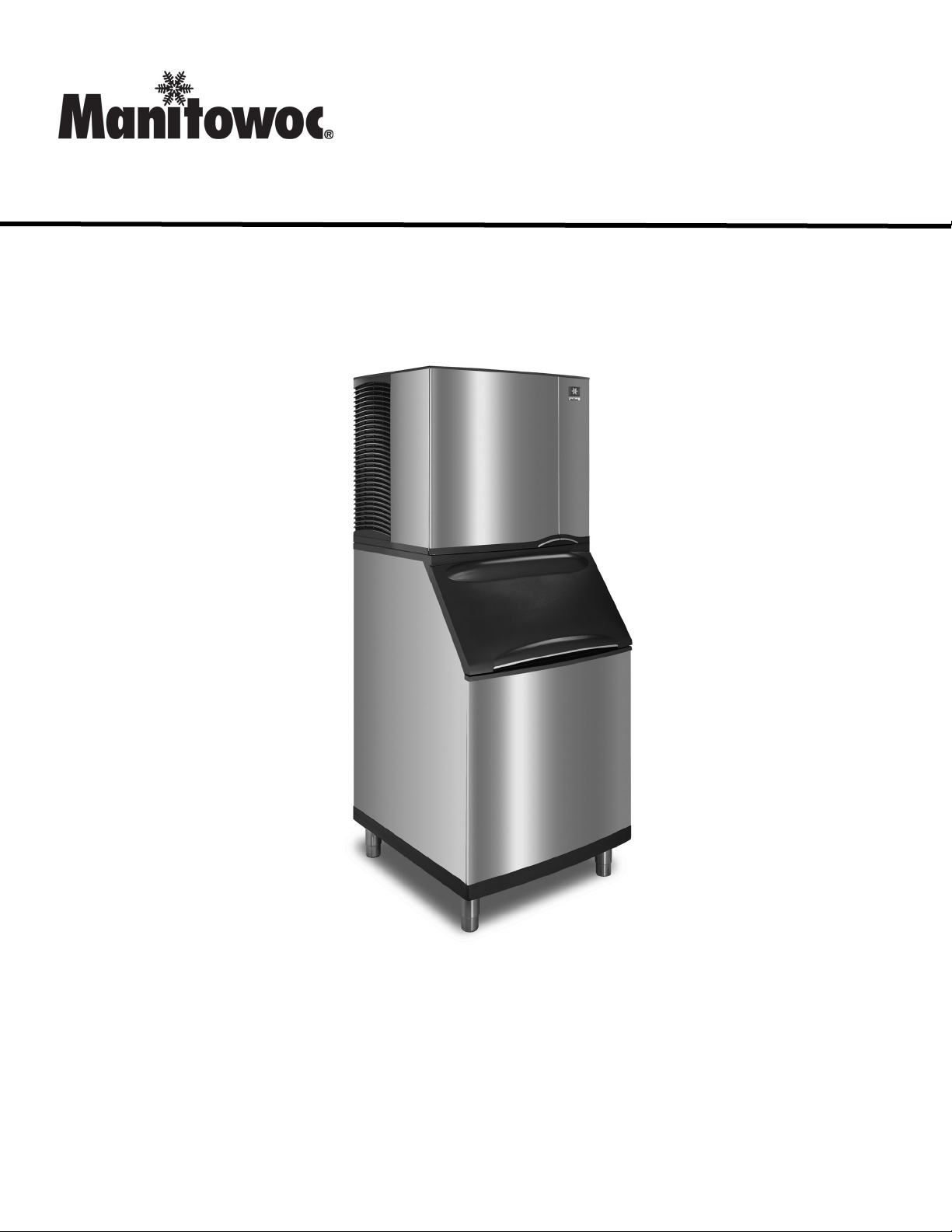
S Model Ice Machines
Installation Operation and Maintenance Manual
Original Document
America’s #1 Selling Ice Machine
Part Number 000006520 Rev 03 12/19
Read this instruction before operating this equipment
Page 2

Section 1
General Information
Model Numbers . . . . . . . . . . . . . . . . . . . . . . . . . . . . . . . . . . . . . . . . . . . . . . . . . . . . . 4
Section 2
Installation Instructions
Location of Ice Machine . . . . . . . . . . . . . . . . . . . . . . . . . . . . . . . . . . . . . . . . . . . . . . 5
Clearance Requirements . . . . . . . . . . . . . . . . . . . . . . . . . . . . . . . . . . . . . . . . . . . . . 5
Ice Machine Heat of Rejection . . . . . . . . . . . . . . . . . . . . . . . . . . . . . . . . . . . . . . . . . 6
Removing Drain Plug and Leveling the Ice Storage Bin . . . . . . . . . . . . . . . . . . . . 6
Air Baffle . . . . . . . . . . . . . . . . . . . . . . . . . . . . . . . . . . . . . . . . . . . . . . . . . . . . . . . . . . 6
Electrical Service . . . . . . . . . . . . . . . . . . . . . . . . . . . . . . . . . . . . . . . . . . . . . . . . . . . 7
Maximum Breaker Size & Minimum Circuit Amperage Chart . . . . . . . . . . . . . . . . 8
Water Supply and Drain Requirements . . . . . . . . . . . . . . . . . . . . . . . . . . . . . . . . . 9
Water Supply and Drain Line Sizing/Connections . . . . . . . . . . . . . . . . . . . . . . . . 10
Remote Condenser/Line Set Installation . . . . . . . . . . . . . . . . . . . . . . . . . . . . . . . . 11
Remote Ice Machine Usage with Non-Manitowoc Multi-Circuit Condensers . . . 15
Installation Check List . . . . . . . . . . . . . . . . . . . . . . . . . . . . . . . . . . . . . . . . . . . . . . . 17
Additional Checks for Remote Models . . . . . . . . . . . . . . . . . . . . . . . . . . . . . . . . . . 17
Before Starting the Ice Machine . . . . . . . . . . . . . . . . . . . . . . . . . . . . . . . . . . . . . . . 17
Table of Contents
Ice Deflector . . . . . . . . . . . . . . . . . . . . . . . . . . . . . . . . . . . . . . . . . . . . . . . . . . . . 4
Bin Installation . . . . . . . . . . . . . . . . . . . . . . . . . . . . . . . . . . . . . . . . . . . . . . . . . . 4
Dispenser Installation . . . . . . . . . . . . . . . . . . . . . . . . . . . . . . . . . . . . . . . . . . . . 4
Voltage . . . . . . . . . . . . . . . . . . . . . . . . . . . . . . . . . . . . . . . . . . . . . . . . . . . . . . . . 7
Fuse/Circuit Breaker . . . . . . . . . . . . . . . . . . . . . . . . . . . . . . . . . . . . . . . . . . . . . 7
Minimum Circuit Ampacity . . . . . . . . . . . . . . . . . . . . . . . . . . . . . . . . . . . . . . . . . 7
Electrical Requirements . . . . . . . . . . . . . . . . . . . . . . . . . . . . . . . . . . . . . . . . . . . 7
Ground Fault Circuit Interrupter . . . . . . . . . . . . . . . . . . . . . . . . . . . . . . . . . . . . . 7
Minimum Power Cord Specifications . . . . . . . . . . . . . . . . . . . . . . . . . . . . . . . . . 7
For United Kingdom Only . . . . . . . . . . . . . . . . . . . . . . . . . . . . . . . . . . . . . . . . . 7
Water Supply . . . . . . . . . . . . . . . . . . . . . . . . . . . . . . . . . . . . . . . . . . . . . . . . . . . 9
Water Inlet Lines . . . . . . . . . . . . . . . . . . . . . . . . . . . . . . . . . . . . . . . . . . . . . . . . 9
Drain Connections . . . . . . . . . . . . . . . . . . . . . . . . . . . . . . . . . . . . . . . . . . . . . . . 9
Water-Cooled Condenser Water Pressure . . . . . . . . . . . . . . . . . . . . . . . . . . . . 9
Cooling Tower Applications (Water-Cooled Models) . . . . . . . . . . . . . . . . . . . . . 9
Remote Ice Machines
Refrigerant Charge . . . . . . . . . . . . . . . . . . . . . . . . . . . . . . . . . . . . . . . . . . . . . . 11
General . . . . . . . . . . . . . . . . . . . . . . . . . . . . . . . . . . . . . . . . . . . . . . . . . . . . . . . 12
Guidelines for Routing Line Sets . . . . . . . . . . . . . . . . . . . . . . . . . . . . . . . . . . . . 12
Calculating Remote Condenser Installation Distances . . . . . . . . . . . . . . . . . . . 13
Lengthening or Reducing Line Set Lengths . . . . . . . . . . . . . . . . . . . . . . . . . . . . 14
Connecting A Line Set . . . . . . . . . . . . . . . . . . . . . . . . . . . . . . . . . . . . . . . . . . . . 14
Remote Receiver Service Valve . . . . . . . . . . . . . . . . . . . . . . . . . . . . . . . . . . . . 14
Warranty . . . . . . . . . . . . . . . . . . . . . . . . . . . . . . . . . . . . . . . . . . . . . . . . . . . . . . 15
Head Pressure Control Valve . . . . . . . . . . . . . . . . . . . . . . . . . . . . . . . . . . . . . . 15
Fan Motor . . . . . . . . . . . . . . . . . . . . . . . . . . . . . . . . . . . . . . . . . . . . . . . . . . . . . 15
Internal Condenser Volume . . . . . . . . . . . . . . . . . . . . . . . . . . . . . . . . . . . . . . . . 15
Condenser T . . . . . . . . . . . . . . . . . . . . . . . . . . . . . . . . . . . . . . . . . . . . . . . . . . 15
Refrigerant Charge . . . . . . . . . . . . . . . . . . . . . . . . . . . . . . . . . . . . . . . . . . . . . . 15
Quick Connect Fittings . . . . . . . . . . . . . . . . . . . . . . . . . . . . . . . . . . . . . . . . . . . . 15
Non-Manitowoc Multi-Circuit Condenser Sizing Chart . . . . . . . . . . . . . . . . . . . . 16
2 Part Number 000006520 Rev 03 12/19
Page 3

Section 3
Operation
Section 4
Maintenance
Table of Contents (continued)
Ice Making Sequence Of Operation . . . . . . . . . . . . . . . . . . . . . . . . . . . . . . . . . . . . 18
Safety limits . . . . . . . . . . . . . . . . . . . . . . . . . . . . . . . . . . . . . . . . . . . . . . . . . . . . 18
Operational Checks . . . . . . . . . . . . . . . . . . . . . . . . . . . . . . . . . . . . . . . . . . . . . . . . . 19
General . . . . . . . . . . . . . . . . . . . . . . . . . . . . . . . . . . . . . . . . . . . . . . . . . . . . . . . 19
Ice Thickness Check . . . . . . . . . . . . . . . . . . . . . . . . . . . . . . . . . . . . . . . . . . . . . 19
Cleaning and Sanitizing . . . . . . . . . . . . . . . . . . . . . . . . . . . . . . . . . . . . . . . . . . . . . 20
General . . . . . . . . . . . . . . . . . . . . . . . . . . . . . . . . . . . . . . . . . . . . . . . . . . . . . . . 20
Cleaning/Sanitizing Procedure . . . . . . . . . . . . . . . . . . . . . . . . . . . . . . . . . . . . . 20
Heavily Scaled Cleaning Procedure . . . . . . . . . . . . . . . . . . . . . . . . . . . . . . . . . 20
Exterior Cleaning . . . . . . . . . . . . . . . . . . . . . . . . . . . . . . . . . . . . . . . . . . . . . . . . 20
Cleaning / Sanitizing Procedure . . . . . . . . . . . . . . . . . . . . . . . . . . . . . . . . . . . . . . . 21
Cleaning Procedure . . . . . . . . . . . . . . . . . . . . . . . . . . . . . . . . . . . . . . . . . . . . . 21
Sanitizing Procedure . . . . . . . . . . . . . . . . . . . . . . . . . . . . . . . . . . . . . . . . . . . . . 22
Procedure to Clean Heavily Scaled Ice Machines . . . . . . . . . . . . . . . . . . . . . . . . 23
Cleaning Procedure . . . . . . . . . . . . . . . . . . . . . . . . . . . . . . . . . . . . . . . . . . . . . 23
Sanitizing Procedure . . . . . . . . . . . . . . . . . . . . . . . . . . . . . . . . . . . . . . . . . . . . . 24
Parts Removal for Cleaning/Sanitizing . . . . . . . . . . . . . . . . . . . . . . . . . . . . . . . . . 26
Exterior Cleaning . . . . . . . . . . . . . . . . . . . . . . . . . . . . . . . . . . . . . . . . . . . . . . . . . . . 28
Door Removal . . . . . . . . . . . . . . . . . . . . . . . . . . . . . . . . . . . . . . . . . . . . . . . . . . . . . . 28
Cleaning the Condenser . . . . . . . . . . . . . . . . . . . . . . . . . . . . . . . . . . . . . . . . . . . . . 28
General . . . . . . . . . . . . . . . . . . . . . . . . . . . . . . . . . . . . . . . . . . . . . . . . . . . . . . . 28
Removal from Service/Winterization . . . . . . . . . . . . . . . . . . . . . . . . . . . . . . . . . . . 28
Section 5
Customer Support
Checklist . . . . . . . . . . . . . . . . . . . . . . . . . . . . . . . . . . . . . . . . . . . . . . . . . . . . . . . . . . 29
Safety Limit Feature . . . . . . . . . . . . . . . . . . . . . . . . . . . . . . . . . . . . . . . . . . . . . . . . . 30
Commercial Ice Machine Warranty . . . . . . . . . . . . . . . . . . . . . . . . . . . . . . . . . . . . 31
Residential Ice Machine Limited Warranty . . . . . . . . . . . . . . . . . . . . . . . . . . . . . . 32
Part Number 000006520 Rev 03 12/19 3
Page 4
Section 1
General Information
Model Numbers
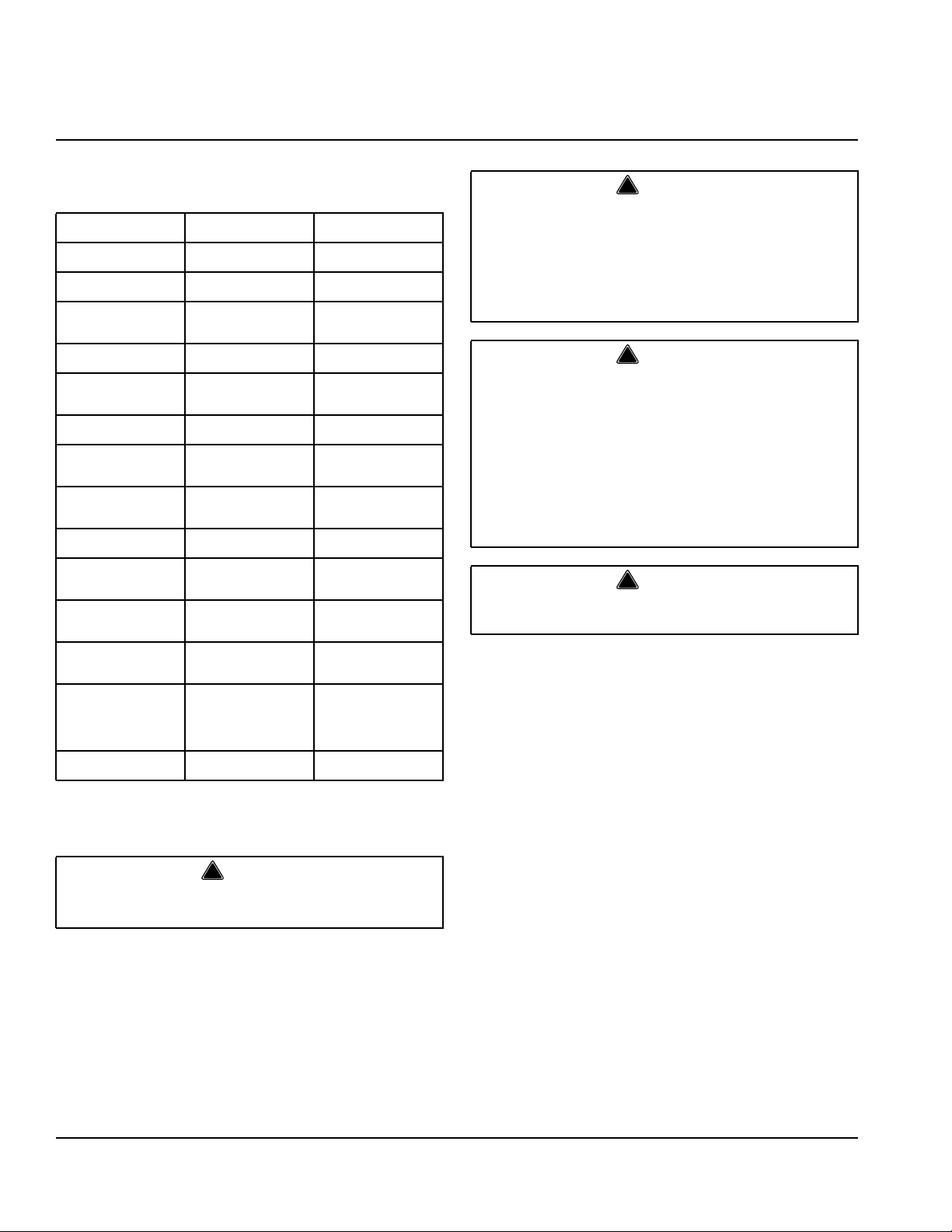
This manual covers the following models:
Self-Contained
Air-Cooled
SD0302A
SY0304A
SD0322A
SY0324A
SR0420A
SD0422A
SY0424A
SD0452A
SY0454A
SR0500A
SD0502A
SY0504A
SD0602A
SY0604A
SR0850A
SD0852A
SY0854A
SD1002A
SY1004A
SD1202A
SY1204A
SD1402A
SY1404A
SR1600A
SD1602A
SY1604A
SR1800A
SD1802A
SY1804A
----
----
----
----
----
----
----
NOTE: Model numbers ending in HP indicate High Pressure water regulating
valve. Standard pressure = 150 psi (10.34 bar) High pressure = 350 psi
(24.13 bar)
Remove all ice machine panels before lifting and
installing.
ICE DEFLECTOR
An ice deflector is required when the ice machine is
installed on a bin. An ice deflector is not required when
the ice machine is installed on a dispenser.
Self-Contained
Water-Cooled
SD0303W
SY0305W
SD0323W
SY0325W
SR0421W
SD0423W
SY0425W
SD0453W
SY0455W
SR0501W
SD0503W
SY0505W
SD0603W
SY0605W
SR0851W
SD0853W
SY0855W
SD1003W
SY1005W
SD1003WM
SD1203W
SY1205W
SD1403W
SY1405W
SD1403WM
SR1601W
SD1603W
SY1605W
SR1801W
SD1803W
SY1805W
SD3303W
SD3303WHP
SY3305W
SY3305WHP
SD3303WM
SYT3000W
SDT3000W
Warning
!
Remote
----
----
----
----
----
----
----
----
----
SR0590N
SD0592N
SY0594N
SD0692N
SY0694N
SR0890N
SD0892N
SY0894N
SD1092N
SY1094N
---
---
SD1492N
SY1494N
SR1690N
SD1692N
SY1694N
SR1890N
SD1892N
SY1894N
----
----
----
----
----
----
----
Warning
!
Manitowoc ice machines require a deflector when
installed on an ice storage bin.
Prior to using a non-Manitowoc ice storage system
with Manitowoc ice machines, contact the
manufacturer to assure their ice deflector is
compatible with Manitowoc ice machines.
Warning
!
Do not operate equipment that has been misused,
abused, neglected, damaged, or altered/modified
from that of original manufactured specifications.
This appliance is not intended for use by persons
(including children) with reduced physical, sensory
or mental capabilities, or lack of experience and
knowledge, unless they have been given
supervision concerning use of the appliance by a
person responsible for their safety.
Warning
!
S3000W/ST3000W ice machines are not approved for use
on Manitowoc B970 or D970 bins.
BIN INSTALLATION
• All ice machines installed on a bin require an ice
deflector.
• Manitowoc bins have a deflector installed and require
no modifications when used with a forward facing
evaporator.
• Ice machines with multiple evaporators require a
deflector kit.
DISPENSER INSTALLATION
• No adapter is needed for machines that match the
size of the dispenser unless required by the
dispenser manufacturer.
• No deflector is required unless specified by the
dispenser manufacturer.
• A bin thermostat to control ice level is recommended.
4 Part Number 000006520 Rev 03 12/19
Page 5
Section 2
Installation Instructions
Location of Ice Machine
The location selected for the ice machine must meet the
following criteria. If any of these criteria are not met,
select another location.
• The location must be free of airborne and other
contaminants.
• The air temperature must be at least 40°F (4.4°C),
but must not exceed 110°F (43.4°C).
• Remote air cooled - The air temperature must be at
least -20°F (-29°C), but must not exceed 120°F
(49°C).
• The location must not be near heat-generating
equipment or in direct sunlight and must be protected
from weather.
• The location must not obstruct air flow through or
around the ice machine. Refer to the chart below for
clearance requirements.
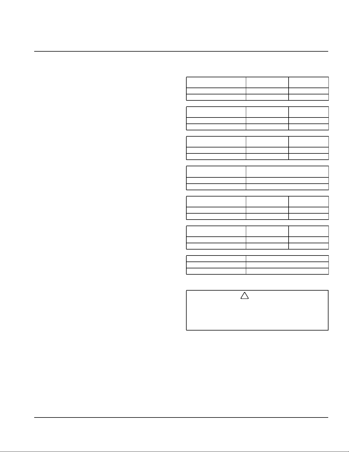
Clearance Requirements
S300
Top/Sides 16" (40.6 cm) 8" (20.3 cm)
Back 5" (12.7 cm) 5" (12.7 cm)
S320/S450/S500/
S600/S850/S1000
Top/Sides 8" (20.3 cm) 8" (20.3 cm)
Back 5" (12.7 cm) 5" (12.7 cm)
S420
Top/Sides 12" (30.5 cm) 8" (20.3 cm)
Back 5" (12.7 cm) 5" (12.7 cm)
S500
230/50/1 Tropical Rating
To p 24" (61 cm)
Sides/Back 12" (30.5 cm)
S1200
To p 8" (20.3 cm) 8" (20.3 cm)
Sides 12" (30.5 cm) 8" (20.3 cm)
S1400/S1600/S1800
Top/Sides 24" (61.0 cm) 8" (20.3 cm)
Back 12" (30.5 cm) 5" (12.7 cm)
Self-Contained
Air-Cooled
Self-Contained
Air-Cooled
Self-Contained
Air-Cooled
Self-Contained
Air-Cooled
Self-Contained
Air-Cooled
Self-Contained
Water-Cooled
Water-Cooled
and Remote
Water-Cooled
and Remote
Self-Contained Air-Cooled
Water-Cooled
and Remote
Water-Cooled
and Remote
S3300/ST3000* Water-Cooled
Top/Sides 8" (20.3 cm)
Back 24" (61.0 cm)
*S3300/ST3000 - 24” on all sides is recommended to allow access
without moving the bin/ice machine.
Caution
!
The ice machine must be protected if it will be
subjected to temperatures below 32°F (0°C). Failure
caused by exposure to freezing temperatures is not
covered by the warranty.
Part Number 000006520 Rev 03 12/19 5
Page 6
Installation Instructions Section 2
Ice Machine Heat of Rejection
Series
Ice Machine
S300 5000 6000
S320 3800 6000
S420 5900 6900
S450 5900 6900
S500 6100 6900
S600 9000 13900
S850 13000 16000
S1000 17700 21000
S1200 20700 24500
S1400 23500 27000
S1600 21000 31000
S1800 30000 35000
S3300 ST3000 45000 51000
B.T.U./Hour
Because the heat of rejection varies during the ice making cycle,
the figure shown is an average.
Air Conditioning
Heat of Rejection
Ice machines, like other refrigeration equipment, reject
heat through the condenser. It is helpful to know the
amount of heat rejected by the ice machine when sizing
air conditioning equipment where self-contained aircooled ice machines are installed.
This information is also necessary when evaluating the
benefits of using water-cooled or remote condensers to
reduce air conditioning loads. The amount of heat added
to an air conditioned environment by an ice machine
using a water-cooled or remote condenser is negligible.
Knowing the amount of heat rejected is also important
when sizing a cooling tower for a water-cooled
condenser. Use the peak figure for sizing the cooling
tower.
Peak
Removing Drain Plug and Leveling the Ice
Storage Bin
1. Remove threaded plug from drain fitting.
2. Screw the leveling legs onto the bottom of the bin.
3. Screw the foot of each leg in as far as possible.
Caution
!
The legs must be screwed in tightly to prevent them
from bending.
4. Move the bin into its final position.
5. Level the bin to assure that the bin door closes and
seals properly. Use a level on top of the bin. Turn the
base of each foot as necessary to level the bin.
6. Inspect bin gasket prior to ice machine installation.
(Manitowoc bins come with a closed cell foam
gasket installed along the top surface of the bin.)
7. Remove all panels from ice machine before lifting.
and installing on bin. Remove both front panels, top
cover, left and right side panels.
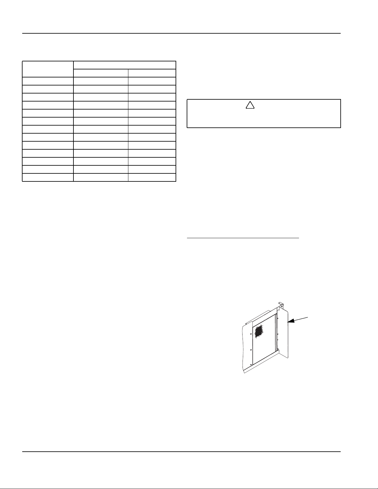
Air Baffle
SELF-CONTAINED AIR-COOLED ONLY
The air-cooled baffle prevents condenser air from
recirculating. To install:
1. Remove the back panel screws next to the
condenser.
2. Align the mounting holes in the air baffle with the
screw holes and reinstall the screws.
AIR
BAFFLE
6
Part Number 000006520 Rev 03 12/19
Page 7
Section 2 Installation Instructions
Electrical Service
Warning
!
All wiring must conform to local, state and national
codes.
VOLTAGE
The maximum allowable voltage variation is ±10% of the
rated voltage at ice machine start-up (when the electrical
load is highest).
Warning
!
The ice machine must be grounded in accordance
with national and local electrical codes.
All electrical work, including wire routing and grounding,
must conform to local, state and national electrical
codes. The following precautions must be observed:
• The ice machine must be grounded.
• A separate fuse/circuit breaker must be provided for
each ice machine.
• A qualified electrician must determine proper wire
size dependent upon location, materials used and
length of run (minimum circuit ampacity can be used
to help select the wire size).
• The maximum allowable voltage variation is +/-10 of
the rated voltage at ice machine start-up (when the
electrical load is highest).
• Check all green ground screws in the control box and
verify they are tight before starting the ice machine.
Important
Observe correct polarity of incoming line voltage.
Incorrect polarity can lead to erratic ice machine
operation.
FUSE/CIRCUIT BREAKER
A separate fuse/circuit breaker must be provided for
each ice machine. Circuit breakers must be H.A.C.R.
rated (does not apply in Canada).
MINIMUM CIRCUIT AMPACITY
The minimum circuit ampacity is used to help select the
wire size of the electrical supply. (Minimum circuit
ampacity is not the ice machine’s running amp load.)
The wire size (or gauge) is also dependent upon
location, materials used, length of run, etc., so it must be
determined by a qualified electrician.
ELECTRICAL REQUIREMENTS
Refer to Ice Machine Model/Serial Plate for voltage/
amperage specifications.
GROUND FAULT CIRCUIT INTERRUPTER
Ground Fault Circuit Interrupter (GFCI/GFI) protection is
a system that shuts down the electric circuit (opens it)
when it senses an unexpected loss of power,
presumably to ground. Manitowoc Ice does not
recommend the use of a GFCI/GFI circuit protection with
our equipment. If code requires the use of a GFCI/GFI
then you must follow the local code. The circuit must be
dedicated, sized properly and there must be a panel
GFCI/GFI breaker. We do not recommend GFCI/GFI
outlets as they are known for more intermittent nuisance
trips than panel breakers.
MINIMUM POWER CORD SPECIFICATIONS
Maximum
Breaker Size
15 amp 14 gauge 6 feet (1.83 m)
20 amp 12 gauge 6 feet (1.83 m)
30 amp 10 gauge 6 feet (1.83 m)
40 amp 8 gauge 6 feet (1.83 m)
Minimum
Wire Size
Maximum Length of
Power Cord
If a power cord is used, the wire size to the receptacle is
dependent upon location, materials used, length of run,
etc., so it must be determined by a qualified electrician.
Local, state or national requirements will supersede our
minimum requirements.
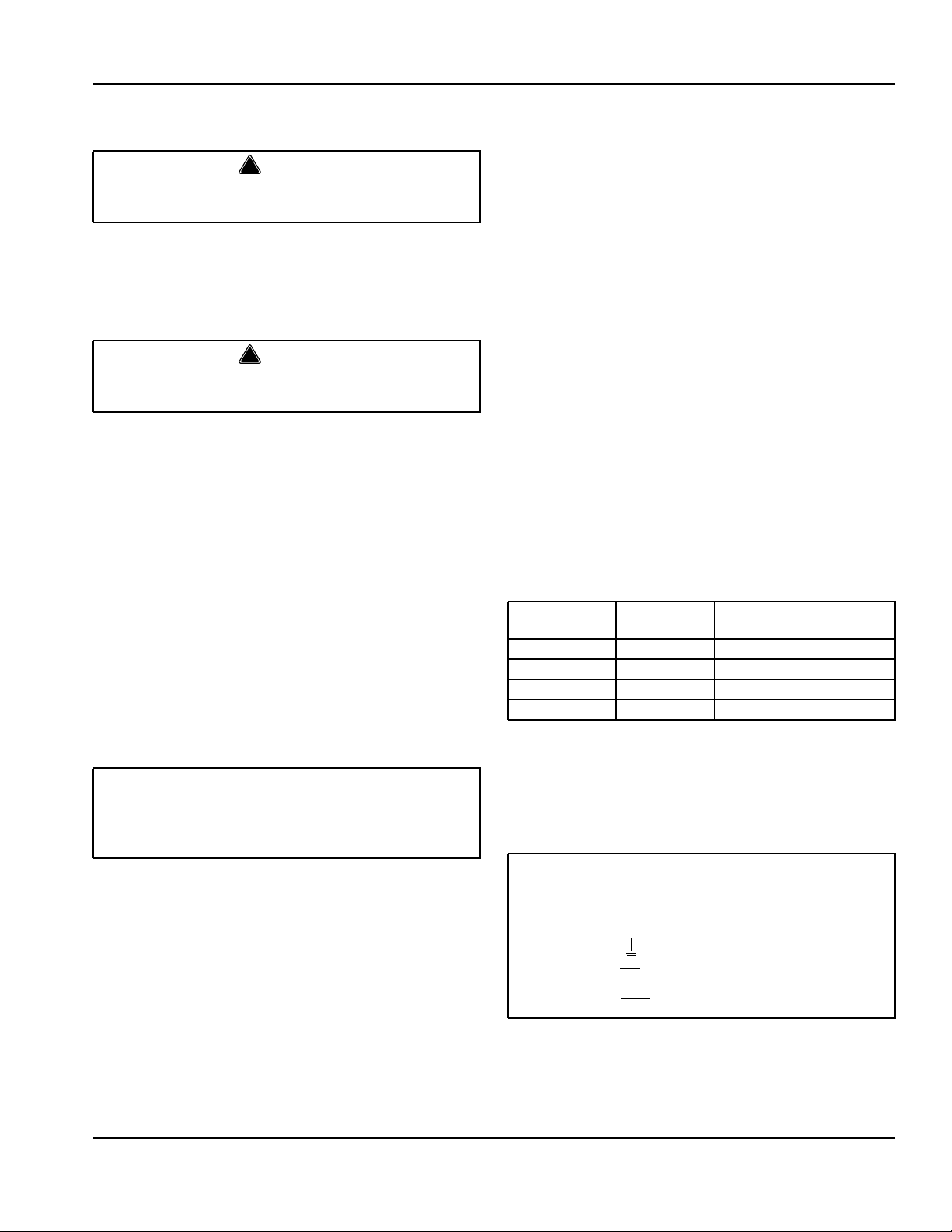
FOR UNITED KINGDOM ONLY
As the colors of the wires in the mains lead of the appliance may not
correspond with the colored markings identifying the terminals in your plug,
proceed as follows:
• The wire which is colored
terminal in the plug which is marked with the letter E or by the earth
ground symbol or colored green or green and yellow.
• The wire colored
with the letter N or colored black.
• The wire colored
marked with the letter L or colored red.
green and yellow must be connected to the
blue must be connected to the terminal which is marked
brown must be connected to the terminal which is
Part Number 000006520 Rev 03 12/19 7
Page 8
Installation Instructions Section 2
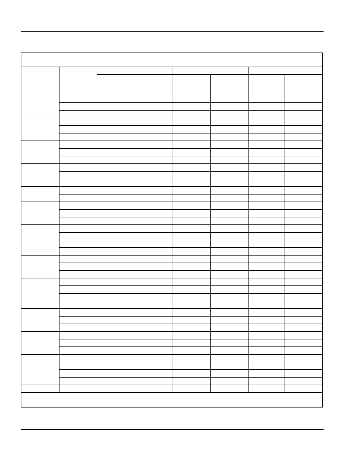
Maximum Breaker Size & Minimum Circuit Amperage Chart.
Due to continuous improvements, this information is for reference only. Please refer to the ice machine serial number
tag to verify electrical data. Serial tag information overrides information listed on this page
Voltage/
Ice Machine
S300
S320
S420/S450
S500
S600
S850
S1000
S1200
S1400
S1600
S1800
S3300
ST3000 208-230/3/60
S3300/ST3000 - Verify the direction of rotation correct is correct on the 3ph scroll compressor. The ice machine will have high suction pressure, low discharge pressure and will be noticeably loud. Reverse any two incoming power leads to reverse rotation.
Phase/
Cycle
115/1/60 25 15.6 25 14.8 N/A N/A
230/1/50 15 7.4 15 6.9 N/A N/A
230/1/60 15 6.7 15 6.3 N/A N/A
115/1/60 15 11.3 15 10.5 N/A N/A
208-230/1/60 15 6.0 15 5.6 N/A N/A
230/1/50 15 6.0 15 5.6 N/A N/A
115/1/60 20 14.2 20 13.5 N/A N/A
208-230/1/60 15 6.1 15 5.7 N/A N/A
230/1/50 15 7.1 15 6.8 N/A N/A
115/1/60 20 20.0 20 13.5 25 20.0
208-230/1/60 15 6.1 15 5.7 15 8.3
230/1/50 15 7.1 15 6.8 15 6.7
208-230/1/60 15 8.3 15 7.9 15 8.9
230/1/50 15 6.7 15 6.1 15 7.1
208-230/1/60 20 11.9 20 10.9 20 11.9
208-230/3/60 15 9.2 15 8.2 15 9.2
230/1/50 20 10.8 20 9.4 15 10.4
208-230/1/60
208-230/3/60
230/1/50
460/3/60
208-230/1/60
208-230/3/60
230/1/50
208-230/1/60 30 18.3 30 16.9 30 17.9
208-230/3/60 20 13.2 20 11.8 20 12.8
230/1/50 30 15.1 30 13.7 30 14.7
440-480/3/60 N/A N/A 15 6.4 N/A N/A
208-230/1/60 30 19.8 30 18.4 30 19.4
208-230/3/60 20 13.5 20 12.1 20 13.1
230/1/50 30 16.7 30 15.3 30 16.3
208-230/1/60
208-230/3/60
230/1/50
208-230/1/60
208-230/3/60
230/1/50
440-480/3/60
Fuse/Circuit
Air-Cooled Water Cooled Remote
Maximum
Breaker
30 17.3 30 16.3 25 15.7
15 10.6 15 9.6 15 10.6
20 12.7 20 11.3 20 12.3
N/A N/A 15 4.5 N/A N/A
35 25.0 35 25.0 N/A N/A
20 16.0 20 16.0 N/A N/A
30 20.0 30 20.0 N/A N/A
40 23.8 40 22.4 40 23.4
25 15.4 25 14.0 25 15.0
40 21.9 40 20.5 40 21.5
N/A N/A N/A N/A N/A N/A
N/A N/A 30 30 N/A N/A
N/A N/A N/A N/A N/A N/A
N/A N/A 15 9.9 N/A N/A
N/A N/A 30 30 N/A N/A
Minimum
Circuit Amps
Maximum
Fuse/Circuit
Breaker
Minimum
Circuit Amps
Maximum
Fuse/Circuit
Breaker
Circuit Amps
Minimum
8
Part Number 000006520 Rev 03 12/19
Page 9
Section 2 Installation Instructions
Water Supply and Drain Requirements
WATER SUPPLY
Local water conditions may require treatment of the
water to inhibit scale formation, filter sediment, and
remove chlorine odor and taste.
WATER INLET LINES
Follow these guidelines to install water inlet lines:
• If you are installing a Manitowoc Arctic Pure water
filter system, refer to the Installation Instructions
supplied with the filter system for ice making water
inlet connections.
• Do not connect the ice machine to a hot water
supply. Be sure all hot water restrictors installed for
other equipment are working. (Check valves on sink
faucets, dishwashers, etc.)
• If water pressure exceeds the maximum
recommended pressure of 80 psi (552 kPa), obtain a
water pressure regulator from your Manitowoc
distributor.
• Install a water shut-off valve for both the ice making
and condenser water lines.
• Insulate water inlet lines to prevent condensation.
Caution
!
Do not apply heat to water valve inlet fitting. This will
damage plastic water inlet connection.
DRAIN CONNECTIONS
Follow these guidelines when installing drain lines to
prevent drain water from flowing back into the ice
machine and storage bin:
• Drain lines must have a 1.5 inch drop per 5 feet of
run (2.5 cm per meter), and must not create traps.
• The floor drain must be large enough to
accommodate drainage from all drains.
• Run separate bin and ice machine drain lines.
Insulate them to prevent condensation.
• Vent the bin and ice machine drain to the
atmosphere. Do not vent the condenser drain on
water-cooled models.
• S3300/ST3000 require a base drain connection (3/4"
FPT).
WATER-COOLED CONDENSER WATER PRESSURE
Water pressure at the condenser cannot exceed 350
psig (10.34 bar).
COOLING TOWER APPLICATIONS
(WATER-COOLED MODELS)
A water cooling tower installation does not require
modification of the ice machine. The water regulator
valve for the condenser continues to control the
refrigeration discharge pressure.
It is necessary to know the amount of heat rejection, and
the pressure drop through the condenser and water
valves (inlet and outlet) when using a cooling tower on
an ice machine.
• Water entering the condenser must not exceed
90°F (32.2°C).
• Water flow through the condenser must not exceed
5 gallons (19 liters) per minute.
• Allow for a pressure drop of 7 psi (0.5 bar) between
the condenser water inlet and the outlet of the ice
machine.
• Water exiting the condenser must not exceed
110°F (43.3°C).
.
Important
The Commonwealth of Massachusetts requires that
all water-cooled models must be connected only to a
closed loop, cooling tower system.
Part Number 000006520 Rev 03 12/19 9
Page 10
Installation Instructions Section 2
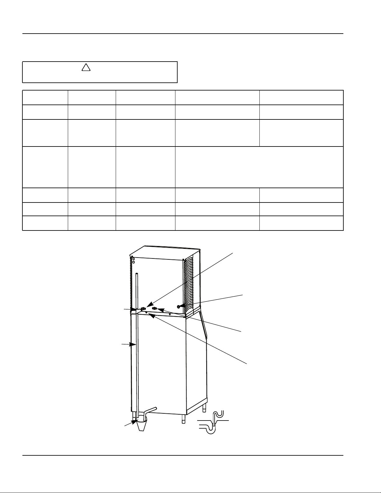
Water Supply and Drain Line Sizing/Connections
Caution
!
Plumbing must conform to state and local codes.
Location
Ice Making
Water Inlet
Ice Making
Water Drain
Condenser
Water Inlet
Condenser
Water Drain
Bin Drain
Large Capacity
Bin Drain
Water
Temperature
35°F (1.6°C) Min.
90°F (32.2°C) Max.
--- ---
90°F (32.2°C) Max.
--- ---
--- --- 3/4" (1.91 cm) Female Pipe Thread
--- --- 1" (2.54 cm) Male Pipe Thread 1" (2.54 cm) min. inside diameter
The exact locations of inlets and drains for the model you are working on may vary.
ELECTRICAL ENTRANCE
Water Pressure Ice Machine Fitting
20 psi (1.4 bar) Min.
80 psi (5.52 bar) Max.
Standard
20 psi (1.4 bar) Min.
150 psi (10.34 bar) Max.
High Pressure Option
20 psi (1.4 bar) Min.
350 psi (24.1 bar) Max.
3/8" (.95 cm) Female Pipe Thread
1/2" (1.27 cm) Female Pipe Thread
3/4" (1.91 cm) FPT S3300/ST3000
3/4" (1.91 cm) FPT Base Drain
S3300/ST3000 Only
3/4" Female Pipe Thread S3300/ST3000 Only
1/2" (1.27 cm) Female Pipe Thread
3/4" (1.91 cm) FPT S3300/ST3000
Tubing Size Up to Ice
Machine Fitting
3/8" (.95 cm) min inside diameter
1/2" (1.27 cm) S3300/ST3000 Only
1/2" (1.27 cm) min inside diameter
3/4" (1.91 cm) S3300/ST3000 Only
3/8" Female Pipe Thread
1/2" (1.27 cm) min inside diameter
3/4" (1.91 cm) S3300/ST3000 Only
3/4" (1.91 cm) minimum
inside diameter
3/8" FPT ICE MAKING WATER INLET FITTING,
PLASTIC FITTING ON OPPOSITE SIDE DO NOT
APPLY HEAT
18" (46 CM) VENT TUBE
1/2" DRAIN CONNECTION
PLASTIC FITTING ON OPPOSITE
SIDE DO NOT APPLY HEAT
1/2" (1.3 CM) MIN
DRAIN ID
AIR GAP
OPEN, TRAPPED AND
VENTED DRAIN
Typical Water Supply Drain Installation
3/8" FPT CONDENSER WATER INLET
(WATER COOLED UNITS ONLY)
1/2" FPT CONDENSER WATER DRAIN
(WATER COOLED UNITS ONLY)
1/2" CPVC SOCKET AUXILLARY
DO NOT TRAP DRAIN LINE,
LEAVE AIR GAP BETWEEN
DRAIN TUBE AND DRAIN
BASE DRAIN
10
Part Number 000006520 Rev 03 12/19
Page 11
Section 2 Installation Instructions
Remote Condenser/Line Set Installation
Remote Single
Ice Machine
S500 JC0495
S600/S800/S1000 JC0895
S1400/S1600/
S1800
*Line Set Discharge Line Liquid Line
RT 1/2" (1.27 cm) 5/16" (.79 cm)
RL 1/2" (1.27 cm) 3/8" (.95 cm)
Air Temperature Around the Condenser
Minimum Maximum
-20°F (-29°C) 120°F (49°C)
Manitowoc remote systems are only approved and
warranted as a complete new package. Warranty on
the refrigeration system will be void if a new ice
machine head section is connected to pre-existing
(used) tubing or remote condensers.
Circuit
Condenser
JC1395
Important
Line Set*
RT-20-R404A
RT-35-R404A
RT-50-R404A
RT-20-R404A
RT-35-R404A
RT-50-R404A
RL-20-R404A
RL-35-R404A
RL-50-R404A
REMOTE ICE MACHINES
REFRIGERANT CHARGE
Each remote ice machine ships from the factory with a
refrigerant charge appropriate for installation with line
sets of up to 50' (15.25 m). The serial tag on the ice
machine indicates the refrigerant charge.
Additional refrigerant may be required for installations
using line sets between 50' and 100' (15.25-30.5 m)
long. If additional refrigerant is required, refer to the
chart below for the correct amount to be added.
Important
EPA CERTIFIED TECHNICIANS
If remote line set length is between 50' and 100'
(15.25 and 30.5 m), add additional refrigerant to the
nameplate charge. Refer to the table below for the
model being worked on.
Tubing length: __________________________________
Refrigerant added to nameplate: ___________________
New total refrigerant charge: ______________________
Warning
!
Potential Personal Injury Situation
The ice machine contains refrigerant charge.
Installation of the line sets must be performed by a
properly trained and EPA certified refrigeration
technician aware of the dangers of dealing with
refrigerant charged equipment.
Caution
!
Never add more than nameplate charge to the
refrigeration system for any application.
Ice Machine
S500 6 lb. (96 oz.) 1.5 lb. (24 oz.) 7.5 lb. (120 oz.)
S600 6.5 lb. (104 oz) 1.5 lb. (24 oz.) 8 lb. (128 oz.)
S850 8.5 lb. (136 oz.) 2 lb. (32 oz.) 10.5 lb. (168 oz.)
S1000 8.5 lb. (136 oz.) 2 lb. (32 oz.) 10.5 lb. (168 oz.)
S1400 11 lb. (176 oz.) 2 lb. (32 oz.) 13 lb. (208 oz.)
S1600 11.5 lb. (184 oz.) 2 lb. (32 oz.) 13.5 lb. (216 oz.)
S1800 12.5 lb. (200 oz.) 1 lb. (16 oz.) 13.5 lb. (216 oz.)
Part Number 000006520 Rev 03 12/19 11
Nameplate Charge
(Charge Shipped in Ice Machine)
Refrigerant to be Added for
50'-100' Line Sets
Maximum System Charge
(Never Exceed)
Page 12
Installation Instructions Section 2
GENERAL
Condensers must be mounted horizontally with the fan
motor on top with nothing obstructing it. There must be
at least a 16" (41 cm) clearance from the bottom for air
intake. The front coupling panel and one other panel
(back or side) must also be unobstructed.
Remote condenser installations consist of vertical and
horizontal line sets between the ice machine and the
condenser. When combined, they must fit within
approved specifications. The following guidelines,
drawings and calculation methods must be followed to
verify a proper remote condenser installation.
Caution
!
The 60 month compressor warranty (including the
36 month labor replacement warranty) will not apply
if the remote ice machine is not installed according
to specifications.
This warranty also will not apply if the refrigeration
system is modified with a condenser, heat reclaim
device, or other parts or assemblies not
manufactured by Manitowoc Ice unless specifically
approved in writing by Manitowoc Ice.
GUIDELINES FOR ROUTING LINE SETS
First, cut a 2.5" (6.35 cm) circular hole in the wall or roof
for tubing routing. The line set end with the 90° bend will
connect to the ice machine. The straight end will connect
to the remote condenser.
Follow these guidelines when routing the refrigerant
lines. This will help ensure proper performance and
service accessibility.
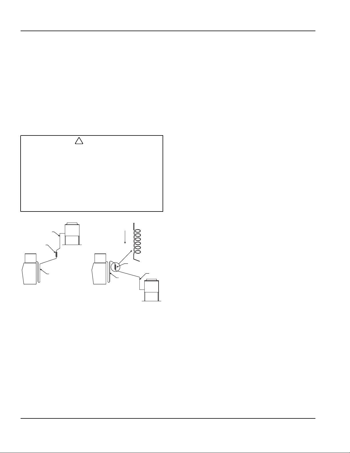
1. Optional - Make the service loop in the line sets (as
shown below). This permits easy access to the ice
machine for cleaning and service. Do not use hard
rigid copper at this location.
2. Required - Do not form traps in the refrigeration lines
(except the service loop). Refrigerant oil must be
free to drain toward the ice machine or the
condenser. Route excess tubing in a supported
downward horizontal spiral (as shown below). Do
not coil tubing vertically.
3. Required - Keep outdoor refrigerant line runs as
short as possible.
3
2
1
DOWNWARD
HORIZONTAL
SPIRAL
2
1
3
Routing Line Sets
12
Part Number 000006520 Rev 03 12/19
Page 13
Section 2 Installation Instructions
CALCULATING REMOTE CONDENSER
INSTALLATION DISTANCES
Line Set Length
The maximum length is 100' (30.5 m).
The ice machine compressor must have the proper oil
return. The receiver is designed to hold a charge
sufficient to operate the ice machine in ambient
temperatures between -20°F (-29°C) and 120°F (49°C),
with line set lengths of up to 100' (30.5 m).
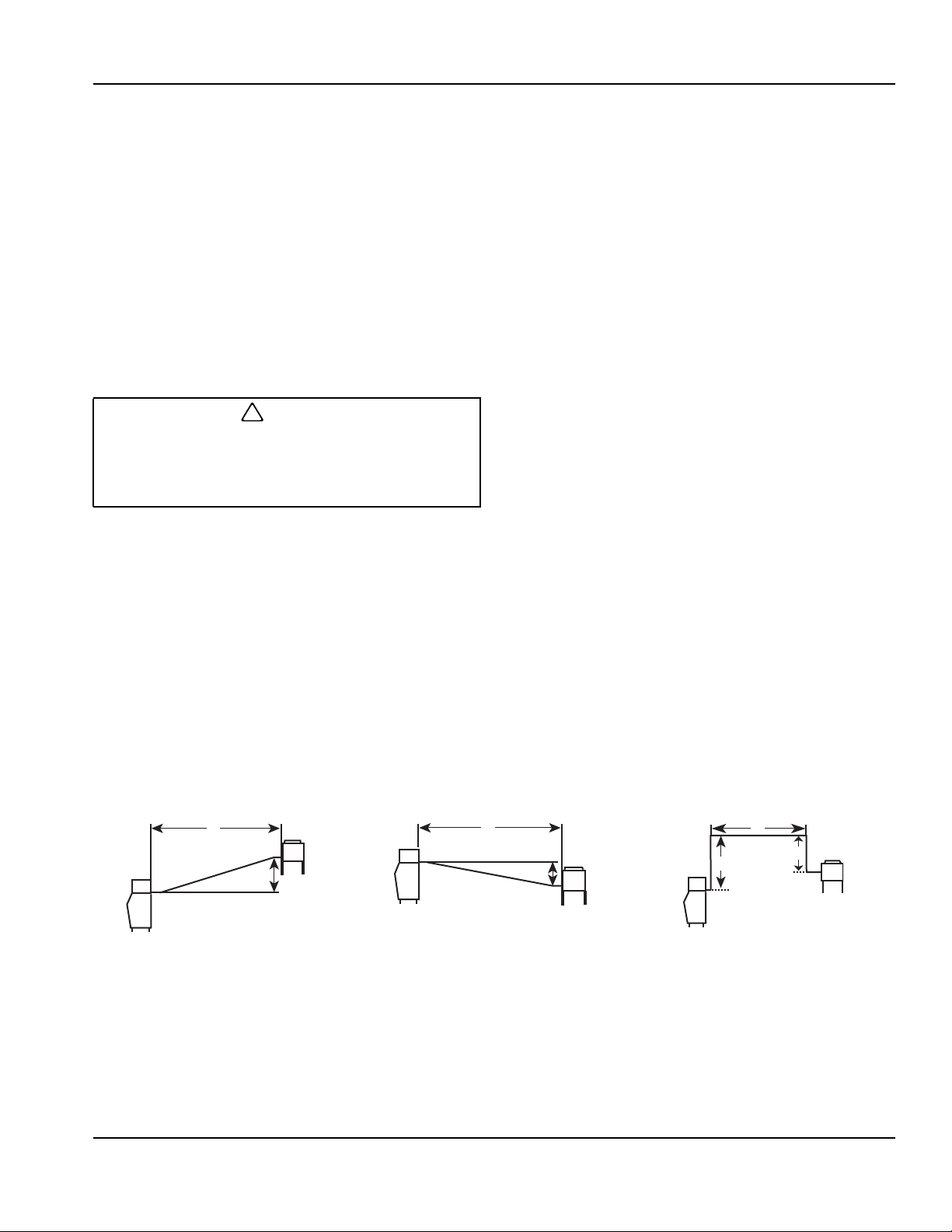
Line Set Rise/Drop
The maximum rise is 35' (10.7 m).
The maximum drop is 15' (4.5 m).
Caution
!
If a line set has a rise followed by a drop, another
rise cannot be made. Likewise, if a line set has a
drop followed by a rise, another drop cannot be
made.
Calculated Line Set Distance
The maximum calculated distance is 150' (45.7 m).
Line set rises, drops, horizontal runs (or combinations of
these) in excess of the stated maximums will exceed
compressor start-up and design limits. This will cause
poor oil return to the compressor.
Make the following calculations to make sure the line set
layout is within specifications.
1. Insert the measured rise into the formula below.
Multiply by 1.7 to get the calculated rise.
(Example: A condenser located 10 feet above the
ice machine has a calculated rise of 17 feet.)
2. Insert the measured drop into the formula below.
Multiply by 6.6 to get the calculated drop.
(Example. A condenser located 10 feet below the
ice machine has a calculated drop of 66 feet.)
3. Insert the measured horizontal distance into the
formula below. No calculation is necessary.
4. Add together the calculated rise, calculated drop,
and horizontal distance to get the total calculated
distance. If this total exceeds 150' (45.7 m), move
the condenser to a new location and perform the
calculations again.
Maximum Line Set Distance Formula
Step 1. Measured Rise (35' [10.7 m] Maximum) ______ x 1.7 = _______ Calculated Rise
Step 2. Measured Drop (15' [4.5 m] Maximum) ______ x 6.6 = _______ Calculated Drop
Step 3. Measured Horizontal Distance (100' [30.5 m] Maximum) _______ Horizontal Distance
Step 4. Total Calculated Distance 150' (45.7 m) _______ Total Calculated Distance
H
R
SV1196 SV1195 SV1194
Combination of a Rise and a
Horizontal Run
H
D
Combination of a Drop and a
Horizontal Run
Combination of a Rise, a Drop
and a Horizontal Run
H
R
D
Part Number 000006520 Rev 03 12/19 13
Page 14
Installation Instructions Section 2
LENGTHENING OR REDUCING LINE SET LENGTHS
In most cases, by routing the line set properly,
shortening will not be necessary. When shortening or
lengthening is required, do so before connecting the line
set to the ice machine or the remote condenser. This
prevents the loss of refrigerant in the ice machine or
condenser.
The quick connect fittings on the line sets are equipped
with Schraeder valves. Use these valves to recover any
vapor charge from the line set. When lengthening or
shortening lines follow good refrigeration practices,
purge with nitrogen and insulate all tubing. Do not
change the tube sizes. Evacuate the lines and place
about 5 oz (143g) of vapor refrigerant charge in each
line.
CONNECTING A LINE SET
1. Remove the dust caps from the line set, condenser
and ice machine.
2. Apply refrigeration oil to the threads on the quick
disconnect couplers before connecting them to the
condenser.
3. Carefully thread the female fitting to the condenser
or ice machine by hand.
4. Tighten the couplings with a wrench until they
bottom out.
5. Turn an additional 1/4 turn to ensure proper brassto-brass seating. Torque to the following
specifications:
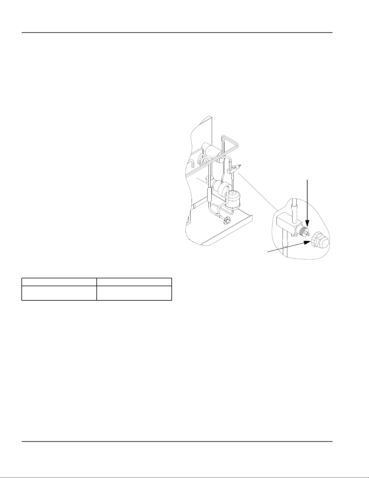
REMOTE RECEIVER SERVICE VALVE
The receiver service valve is closed during shipment.
Open the valve prior to starting the ice machine.
1. Remove the top and left side panels.
2. Remove the receiver service valve cap.
3. Backseat (open) the valve.
4. Reinstall the cap and panels.
REMOVE FRONT, TOP,
AND LEFT SIDE PANEL
FOR ACCESS TO
RECEIVER VALVE
TURN
COUNTERCLOCKWISE
TO OPEN
RECEIVER SERVICE
VALVE CAP (TURN
SV1603
COUNTERCLOCKWISE
TO REMOVE)
Liquid Line Discharge Line
10-12 ft lb.
(13.5-16.2 N•m)
35-45 ft lb.
(47.5-61.0 N•m)
6. Check all fittings and valve caps for leaks.
7. Make sure Schraeder cores are seated and
Schraeder caps are on and tight.
14
Backseating the Receiver Service Valve
Part Number 000006520 Rev 03 12/19
Page 15
Section 2 Installation Instructions
Remote Ice Machine Usage with Non-Manitowoc Multi-Circuit Condensers
WARRANTY
The sixty (60) month compressor warranty, including
thirty six (36) month labor replacement warranty, shall
not apply when the remote ice machine is not installed
within the remote specifications. The foregoing warranty
shall not apply to any ice machine installed and/or
maintained inconsistent with the technical instructions
provided by Manitowoc Ice, Inc. Performance may vary
from Sales specifications. S-Model ARI certified
standard ratings only apply when used with a Manitowoc
remote condenser.
If the design of the condenser meets the specifications,
Manitowoc’s
to be extended to the Manitowoc manufactured part of
the system. Since Manitowoc does not test the
condenser in conjunction with the ice machine,
Manitowoc will not endorse, recommend, or approve the
condenser, and will not be responsible for its
performance or reliability.
only approval is for full warranty coverage
Important
Manitowoc warrants only complete new and unused
remote packages. Guaranteeing the integrity of a
new ice machine under the terms of our warranty
prohibits the use of pre-existing (used) tubing or
condensers.
HEAD PRESSURE CONTROL VALVE
Any remote condenser connected to a Manitowoc
S-Model Ice Machine must have a head pressure control
valve (available from Manitowoc Distributors) installed
on the condenser package. Manitowoc will not accept
substitute “off the shelf” head pressure control valves.
FAN MOTOR
The condenser fan must be on during the complete ice
machine freeze cycle (do not cycle on fan cycle control).
The ice maker has a condenser fan motor circuit for use
with a Manitowoc condenser. It is recommended that this
circuit be used to control the condenser fan(s) on the
multi-circuit condenser to assure it is on at the proper
time. Do not exceed the rated amps for the fan motor
circuit listed on the ice machine’s serial tag.
INTERNAL CONDENSER VOLUME
The multi-circuit condenser internal volume must not be
less than or exceed that used by Manitowoc (see chart
on next page). Do not exceed internal volume and try
to add charge to compensate, as compressor failure
will result.
CONDENSER T
T is the difference in temperature between the
condensing refrigerant and entering air. The T should
be 15 to 20°F (-9.4 to -6.6°C) at the beginning of the
freeze cycle (peak load conditions) and drop down to
12 to 17°F (-11.1 to -8.3°C) during the last 75% of the
freeze cycle (average load conditions).
REFRIGERANT CHARGE
Remote ice machines have the serial plate refrigerant
charge (total system charge) located in the ice maker
section. (Remote condensers and line sets are supplied
with only a vapor charge.)
Caution
!
Never add more than nameplate charge to ice
machine for any application.
Caution
!
Do not use a fan cycling control to try to maintain
discharge pressure. Compressor failure will result.
Part Number 000006520 Rev 03 12/19 15
QUICK CONNECT FITTINGS
The ice machine and line sets come with quick connect
fittings. It is recommended that matching quick connects
(available through Manitowoc Distributors) be installed in
the multi-circuit condenser, and that a vapor “holding”
charge, 5 oz. (150 ml), of proper refrigerant be added to
the condenser prior to connection of the ice machine or
line set to the condenser.
Page 16
Installation Instructions Section 2
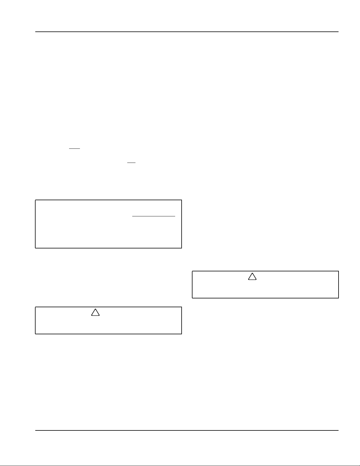
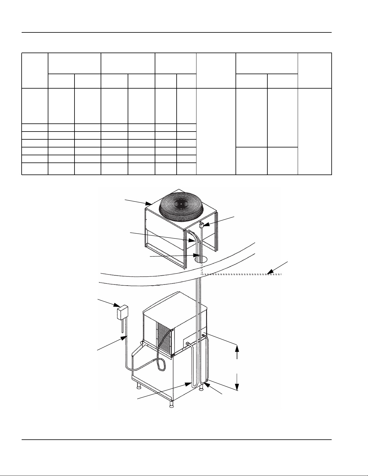
NON-MANITOWOC MULTI-CIRCUIT CONDENSER SIZING CHART
Internal
Ice
Machine
Model
Refrigerant Heat of Rejection
Type Charge
Average
Btu/hr
Peak
Btu/hr
Condenser
Volume (cu ft)
Design
Pressure
Min Max Discharge Liquid
500 psig
(3447 kpa)
S500 R-404A
6 lbs. 6,100 6,900 0.020 0.035
(34.47 bar)
safe working
pressure
S600 R404A
6.5 lbs. 9,000 13,900 0.045 0.060
S850 R-404A 8.5 lbs. 13,000 16,000 0.045 0.060 2,500 psig
S1000 R-404A 8.5 lbs. 17,700 21,000 0.045 0.060
S1400 R-404A 11 lbs. 20,700 24,500 0.085 0.105
S1600 R-404A 11.5 lbs 21,000 31,000
S1800 R-404A 12.5 lbs. 30,000 35,000
SINGLE CIRCUIT
REMOTE CONDENSER
DISCHARGE
LINE
0.085 0.105
0.085 0.105
(17237 kpa)
(172.37 bar)
burst
pressure
Quick Connect Stubs-
Male Ends
coupling
P/N
83-6035-3
mounting
flange P/N
83-6006-3
ELECTRICAL
DISCONNECT
coupling
P/N
83-6034-3
mounting
flange P/N
83-6005-3
Head
Pressure
Control
Valve
Manitowoc
P/N
83-6809-3
no
substitutes
ELECTRICAL
DISCONNECT
ELECTRICAL
SUPPLY
LIQUID LINE
ICE MACHINE
36.00"
(91.44 cm)
DROP
LIQUID
REFRIGERANT
LINE
DISCHARGE
REFRIGERANT
LINE
BIN
Typical Single Circuit Remote Condenser Installation
TO CIRCUIT
BREAKER
PANEL
16
Part Number 000006520 Rev 03 12/19
Page 17
Section 2 Installation Instructions
Installation Check List
Is the Ice Machine level?
Have all of the electrical and water
connections been made?
Has the supply voltage been tested and
checked against the rating on the nameplate?
Is there proper clearance around the ice
machine for air circulation?
Is the ice machine grounded and polarity
correct?
Has the ice machine been installed where
ambient temperatures will remain in the
range of 35° - 110°F (1.6° - 43.3°C)?
Has the ice machine been installed where the
incoming water temperature will remain in the
range of 35° - 90°F (1.6° - 32.2°C)?
Is there a separate drain for the potable
water, bin and water-cooled condenser?
Are the ice machine and bin drains vented?
S3300/ST3000 Only - Is the compressor
direction of rotation correct? The ice machine
will have high suction pressure, low
discharge pressure and will be noticeably
loud. Reverse any two incoming power leads
to reverse rotation.
Additional Checks for Remote Models
Has the receiver service valve been opened?
Does the remote condenser fan operate
properly after start-up?
Has the remote condenser been located
where ambient temperatures will remain in
the range of -20° - 120°F (-29 - 49°C).
Is the line set routed properly?
Are both refrigeration lines to remote
condenser run so they do not lay in water and
are properly insulated?
Before Starting the Ice Machine
Are all electrical leads free from contact with
refrigeration lines and moving equipment?
Has the owner/operator been instructed
regarding maintenance and the use of
Manitowoc Cleaner and Sanitizer?
Has the owner/operator completed the
warranty registration card?
Has the ice machine and bin been sanitized?
Is the toggle switch set to ice? (The toggle
switch is located directly behind the front
panel).
Is the ice thickness control set correctly?
(Refer to Operational Checks to check/set the
correct ice bridge thickness).
All Manitowoc ice machines are factory-operated and
adjusted before shipment. Normally, new installations do
not require any adjustment.
To ensure proper operation, follow the Operational
Checks in Section 3 of this manual. Starting the ice
machine and completing the Operational Checks are the
responsibilities of the owner/operator.
Adjustments and maintenance procedures outlined in
this manual are not covered by the warranty.
Warning
!
Potential Personal Injury Situation
Do not operate equipment that has been misused.
abused, neglected, damaged, or altered/modified
from that of original manufactured specifications.
Part Number 000006520 Rev 03 12/19 17
Page 18

Ice Making Sequence Of Operation
Section 3
Operation
NOTE: The toggle switch must be in the ice position and
the water curtain/ice dampers must be in place on the
evaporator before the ice machine will start.
Water Purge Cycle
The ice machine purges any remaining water from the
water trough down the drain.
Freeze Cycle
Water flows across the evaporator and the refrigeration
system chills the evaporator. Ice builds on the
evaporator until water contacts the ice thickness probe.
Harvest Cycle
Any remaining water is purged down the drain as
refrigerant gas warms the evaporator. When the
evaporator warms, the sheet of cubes slides off the
evaporator and into the storage bin. If all cubes fall clear
of the water curtain (or ice damper) the ice machine
starts another freeze cycle.
Off Cycle
If the water curtain or ice damper are held open by ice
cubes the ice machine shuts off. When the water curtain
or ice damper closes the ice machine starts a new cycle
at the water purge.
Control Board Timers
The control board has the following non-adjustable
timers:
• The ice machine is locked into the freeze cycle for 6
minutes before a harvest cycle can be initiated.
Freeze lock is bypassed after moving the toggle
switch from OFF to ICE position for the first cycle
only.
• The maximum freeze time is 60 minutes at which
time the control board automatically initiates a
harvest sequence.
• The maximum harvest time is 3.5 minutes for single
evaporators and 7 minutes for multiple evaporator
model. The control board automatically initiates a
freeze sequence when these times are exceeded.
SAFETY LIMITS
Safety limits are stored and indicated by the control
board after three cycles. The number of cycles required
to stop the ice machine varies for each safety limit.
• Safety Limit 1 all models - If the freeze time reaches
60 minutes, the control board automatically initiates a
harvest cycle. If 6 consecutive 60-minute freeze
cycles occur, the ice machine stops.
• Safety Limit 2 single evaporator models - If the
harvest time reaches 3.5 minutes, the control board
automatically returns the ice machine to the freeze
cycle. If 500 consecutive 3.5 minute harvest cycles
occur, the ice machine stops.
• Safety Limit 2 multiple evaporator models - If the
harvest time reaches 7 minutes, the control board
automatically returns the ice machine to the freeze
cycle. If 500 consecutive 7 minute harvest cycles
occur, the ice machine stops.
• Safety Limit 3 multiple evaporator models - If the low
refrigerant pressure control opens, the ice machine
shuts off and starts a 5 minute delay period. If 3
consecutive low pressure events occur, the ice
machine stops and flashes the harvest light.
Use the following procedures to determine if the control
board contains a safety limit indication.
1. Move the toggle switch to OFF.
2. Move the toggle switch back to ICE. Watch the
safety limit lights/harvest light on the control board. If
a safety limit has been recorded, the corresponding
light will blink once, twice or three times to indicate
which safety limit stopped the ice machine.
18 Part Number 000006520 Rev 03 12/19
Page 19
Section 3 Operation
Operational Checks
GENERAL
Manitowoc ice machines are factory-operated and
adjusted before shipment. Normally, new installations do
not require any adjustment.
To ensure proper operation, always follow the
Operational Checks:
• when starting the ice machine for the first time
• after a prolonged out of service period
• after cleaning and sanitizing
NOTE: Routine adjustments and maintenance
procedures are not covered by the warranty.
Important
Scroll refrigeration compressors must be
operated for a minimum break in period of 24
hours before full ice production will be reached.
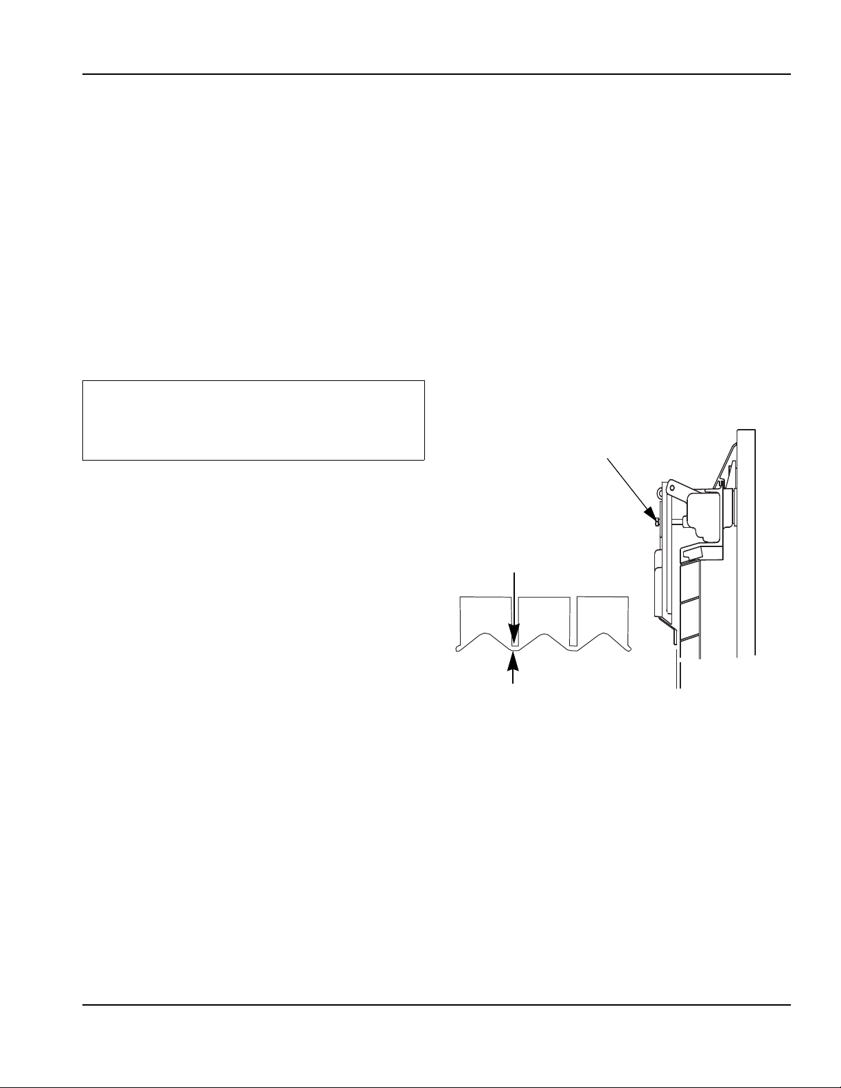
ICE THICKNESS CHECK
After a harvest cycle, inspect the ice cubes in the ice
storage bin. The ice thickness probe is factory-set to
maintain the ice bridge thickness at 1/8" (3 mm).
NOTE: Make sure the water curtain is in place when
performing this check. It prevents water from splashing
out of the water trough.
1. Inspect the bridge connecting the cubes. It should
be about 1/8" (3 mm) thick.
2. If adjustment is necessary, turn the ice thickness
probe adjustment screw clockwise to increase
bridge thickness, counterclockwise to decrease
bridge thickness. Set at 1/4" (6 mm) gap between
ice machine and evaporator as starting point, then
adjust to achieve a 1/8" (3 mm) bridge thickness.
NOTE: Turning the adjustment 1/3 of a turn will change
the ice thickness about 1/16" (1.5 mm).
ADJUSTING SCREW
1/8" (3 mm)
ICE BRIDGE THICKNESS
Ice Thickness Check
3. Make sure the ice thickness probe wire and the
bracket do not restrict movement of the probe.
Part Number 000006520 Rev 03 12/19 19
Page 20
Section 4
Maintenance
Descaling and Sanitizing
GENERAL
You are responsible for maintaining the ice machine in
accordance with the instructions in this manual.
Maintenance procedures are not covered by the
warranty.
Descale and sanitize the ice machine every six months
for efficient operation. If the ice machine requires more
frequent descaling and sanitizing, consult a qualified
service company to test the water quality and
recommend appropriate water treatment. An extremely
dirty ice machine must be taken apart for cleaning and
sanitizing.
Manitowoc Ice Machine Cleaner and Sanitizer are the
only products approved for use in Manitowoc ice
machines.
Caution
!
Use only Manitowoc approved Ice Machine Cleaner/
Descaler and Sanitizer for this application
(Manitowoc Cleaner part number 94-0546-3 and
Manitowoc Sanitizer part number 94-0565-3). It is a
violation of Federal law to use these solutions in a
manner inconsistent with their labeling. Read and
understand all labels printed on bottles before use.
Caution
!
Do not mix Cleaner/Descaler and Sanitizer solutions
together. It is a violation of Federal law to use these
solutions in a manner inconsistent with their
labeling.
Warning
!
Wear rubber gloves and safety goggles (and/or face
shield) when handling Ice Machine Cleaner or
Sanitizer.
CLEANING/SANITIZING PROCEDURE
This procedure must be performed a minimum of once
every six months.
• The ice machine and bin must be disassembled
cleaned and sanitized.
• All ice produced during the cleaning and sanitizing
procedures must be discarded.
• Removes mineral deposits from areas or surfaces
that are in direct contact with water.
REMEDIAL CLEANING PROCEDURE
Perform this procedure if you have some or all of these
symptoms.
• Ice machine stops on Safety Shutdown.
• Your water has a high concentration of minerals.
• The ice machine has not been on a regular
maintenance schedule.
DETAILED DESCALING/SANITIZING PROCEDURE
This procedure must be performed a minimum of once
every six months.
• The ice machine and bin must be disassembled
descaled and sanitized.
• All ice produced during the descaling and sanitizing
procedures must be discarded.
EXTERIOR CLEANING
Clean the area around the ice machine as often as
necessary to maintain cleanliness and efficient
operation. Use cleaners designed for use with stainless
steel products.
Sponge any dust and dirt off the outside of the ice
machine with mild soap and water. Wipe dry with a
clean, soft cloth.
Heavy stains should be removed with stainless steel
wool. Never use plain steel wool or abrasive pads. They
will scratch the panels.
20 Part Number 000006520 Rev 03 12/19
Page 21
Section 4 Maintenance
Remedial Cleaning Procedure
Step 3 Remove all ice from the bin/dispenser.
Caution
!
Use only Manitowoc approved Ice Machine Cleaner/
Descaler and Sanitizer for this application
(Manitowoc Cleaner/Descaler part number 94-05463 and Manitowoc Sanitizer part number 94-0565-3).
It is a violation of Federal law to use these solutions
in a manner inconsistent with their labeling. Read
and understand all labels printed on bottles before
use.
REMEDIAL DESCALING/SANITIZING PROCEDURE
Caution
!
Do not mix Cleaner and Sanitizer solutions together.
It is a violation of Federal law to use these solutions
in a manner inconsistent with their labeling.
Warning
!
Wear rubber gloves and safety goggles (and/or face
shield) when handling Ice Machine Cleaner or
Sanitizer.
Ice machine descaler is used to remove lime scale and
mineral deposits. Ice machine sanitizer disinfects and
removes algae and slime.
Step 1 Remove front door and top cover. This will allow
easiest access for adding cleaning and sanitizing
solutions.
Step 2 Set the toggle switch to the OFF position after
ice falls from the evaporator at the end of a Harvest
cycle. Or, set the switch to the OFF position and allow
the ice to melt off the evaporator.
Step 4 Place the toggle switch in the CLEAN position.
The water will flow through the water dump valve and
down the drain. Wait until the water trough refills and
water flows over the evaporator, then add the proper
amount of ice machine cleaner.
Model
S300/S320/S420 3 ounces (90 ml)
S450/S500/S600/S850/
S1000/S1200
S1400/S1600/S1800 9 ounces (265 ml)
S3300/ST3000 16 ounces (475 ml)
Step 5 Wait until the clean cycle is complete
(approximately *35 minutes). Then place the toggle
switch in the OFF position and disconnect power to the
ice machine (and dispenser when used).
NOTE: *S3300/ST3000 Only - 80 minutes.
Warning
!
Disconnect the electric power to the ice machine at
the electric service switch box.
Step 6 Remove parts for cleaning.
Please refer to the proper parts removal for your ice
machine. Continue with step 7 when the parts have
been removed.
Single Evaporator Ice Machines - Page 26
Multiple Evaporator Ice Machines - Page 27
Amount of
Cleaner/Descaler
5 ounces (150 ml)
Caution
!
Never use anything to force ice from the evaporator.
Damage may result.
Part Number 000006520 Rev 03 12/19 21
Page 22
Maintenance Section 4
Step 7 Mix a solution of cleaner/descaler and warm
water. Depending upon the amount of mineral buildup, a
larger quantity of solution may be required. Use the ratio
in the table below to mix enough solution to thoroughly
clean all parts.
Solution Type Water Mixed With
Cleaner 1 gal. (4 L) 16 oz (500 ml) cleaner
Step 8 Use 1/2 of the descaler/water mixture to
descale all components. The descaler solution will foam
when it contacts lime scale and mineral deposits; once
the foaming stops use a soft-bristle nylon brush, sponge
or cloth (NOT a wire brush) to carefully clean the parts.
Soak parts for 5 minutes (15 - 20 minutes for heavily
scaled parts). Rinse all components with clean water.
Step 9 While components are soaking, use 1/2 of the
descaler/water solution to clean all foodzone surfaces of
the ice machine and bin (or dispenser). Use a nylon
brush or cloth to thoroughly descale the following ice
machine areas:
• Side walls
• Base (area above water trough)
• Evaporator plastic parts - including top, bottom, and
sides
• Bin or dispenser
Rinse all areas thoroughly with clean water.
SANITIZING PROCEDURE
Step 10 Mix a solution of sanitizer and warm water.
Step 12 Use 1/2 of the sanitizer/water solution to
sanitize all foodzone surfaces of the ice machine and bin
(or dispenser). Use a spray bottle to liberally apply the
solution. When sanitizing, pay particular attention to the
following areas:
• Side walls
• Base (area above water trough)
• Evaporator plastic parts - including top, bottom and
sides
• Bin or dispenser
Do not rinse the sanitized areas.
Step 13 Replace all removed components.
Step 14 Wait 30 minutes.
Step 15 Reapply power to the ice machine and place
the toggle switch in the CLEAN position.
Step 16 Wait until the water trough refills and water
flows over the evaporator (approximately 3 minutes).
Add the proper amount of Manitowoc Ice Machine
Sanitizer to the water trough by pouring between the
water curtain and evaporator.
Model Amount of Sanitizer
S300/S320/S420 3 ounces (90 ml)
S450/S500/S600/S850/
S1000/S1200
S1400/S1600/S1800 6 ounces (180 ml)
S3300/ST3000 25 ounces (740 ml)
3 ounces (90 ml)
Solution Type Water Mixed With
Sanitizer 6 gal. (23 L) 4 oz (120 ml) sanitizer
Step 11 Use 1/2 of the sanitizer/water solution to
sanitize all removed components. Use a spray bottle to
liberally apply the solution to all surfaces of the removed
parts or soak the removed parts in the sanitizer/water
solution. Do not rinse parts after sanitizing.
22
Step 17 Move the toggle switch to the ICE position
and replace the front panel. The ice machine will
automatically start ice making after the sanitize cycle
is complete (approximately 35 minutes,
S3300/ST3000 80 minutes).
Part Number 000006520 Rev 03 12/19
Page 23
Section 4 Maintenance
Detailed Descaling and Sanitizing Procedure
Ice machines that are heavily scaled or have not been cleaned on a regular basis will need to run this procedure.
Clean and sanitize the ice machine every six months for
efficient operation. If the ice machine requires more
frequent cleaning and sanitizing, consult a qualified
service company to test the water quality and
recommend appropriate water treatment. The ice
machine must be taken apart for cleaning and sanitizing.
Caution
!
Use only Manitowoc approved Ice Machine Cleaner/
Descaler and Sanitizer for this application
(Manitowoc Cleaner part number 94-0546-3 and
Manitowoc Sanitizer part number 94-0565-3). It is a
violation of Federal law to use these solutions in a
manner inconsistent with their labeling. Read and
understand all labels printed on bottles before use
Step 3 Remove all ice from the bin.
Step 4 Place the toggle switch in the CLEAN position.
The water will flow through the water dump valve and
down the drain. Wait until the water trough refills and
water flows over the evaporator, then add the proper
amount of ice machine cleaner.
Model
S300/S320/S420 3 ounces (90 ml)
S450/S500/S600/S850/
S1000/S1200
S1400/S1600/S1800 9 ounces (265 ml)
S3300/ST3000 16 ounces (475 ml)
Amount of
Cleaner/Descaler
5 ounces (150 ml)
CLEANING PROCEDURE
Caution
!
Do not mix Cleaner/Descaler and Sanitizer solutions
together. It is a violation of Federal law to use these
solutions in a manner inconsistent with their
labeling.
Warning
!
Wear rubber gloves and safety goggles (and/or face
shield) when handling Ice Machine Cleaner or
Sanitizer.
Ice machine cleaner/descaler is used to remove lime
scale and mineral deposits. Ice machine sanitizer
disinfects and removes algae and slime.
Step 1 Set the toggle switch to the OFF position after
ice falls from the evaporator at the end of a Harvest
cycle. Or, set the switch to the OFF position and allow
the ice to melt off the evaporator.
Caution
!
Never use anything to force ice from the evaporator.
Damage may result.
Step 5 Wait until the clean cycle is complete
(approximately *35 minutes). Then place the toggle
switch in the OFF position and disconnect power to the
ice machine (and dispenser when used).
NOTE: *S3300/ST3000 Only - 80 minutes.
Warning
!
Disconnect the electric power to the ice machine at
the electric service switch box.
Step 6 Remove parts for cleaning.
Please refer to the proper parts removal for your ice
machine.
Single Evaporator Ice Machines - Page 26
Multiple Evaporator Ice Machines - Page 27
Step 2 Remove top cover. This will allow easiest
access for adding descaling and sanitizing solutions.
Part Number 000006520 Rev 03 12/19 23
Page 24
Maintenance Section 4
Step 7 Mix a solution of descaler and warm water.
Depending upon the amount of mineral buildup, a larger
quantity of solution may be required. Use the ratio in the
table below to mix enough solution to thoroughly clean
all parts.
Solution Type Water Mixed With
Descaler 1 gal. (4 L) 16 oz (500 ml)
cleaner/descaler
Step 8 Use 1/2 of the descaler/water mixture to
descale all components. The descaler solution will foam
when it contacts lime scale and mineral deposits; once
the foaming stops use a soft-bristle nylon brush, sponge
or cloth (NOT a wire brush) to carefully clean the parts.
Soak parts for 5 minutes (15 - 20 minutes for heavily
scaled parts). Rinse all components with clean water.
Step 9 While components are soaking, use 1/2 of the
descaler/water solution to descale all foodzone surfaces
of the ice machine and bin (or dispenser). Use a nylon
brush or cloth to thoroughly clean the following ice
machine areas:
• Side walls
• Base (area above water trough)
• Evaporator plastic parts - including top, bottom, and
sides
• Bin or dispenser
Rinse all areas thoroughly with clean water.
SANITIZING PROCEDURE
Step 10 Mix a solution of sanitizer and warm water.
Solution Type Water Mixed With
Sanitizer 6 gal. (23 L) 4 oz (120 ml) sanitizer
Step 11 Use 1/2 of the sanitizer/water solution to
sanitize all removed components. Use a cloth or sponge
to liberally apply the solution to all surfaces of the
removed parts or soak the removed parts in the
sanitizer/water solution. Do not rinse parts after
sanitizing.
Step 12 Use 1/2 of the sanitizer/water solution to
sanitize all foodzone surfaces of the ice machine and bin
(or dispenser). Use a cloth or sponge to liberally apply
the solution. When sanitizing, pay particular attention to
the following areas:
• Side walls
• Base (area above water trough)
• Evaporator plastic parts - including top, bottom and
sides
• Bin or dispenser
Do not rinse the sanitized areas.
Step 13 Replace all removed components.
Step 14 Reapply power to the ice machine and place
the toggle switch in the CLEAN position.
Step 15 Wait about two minutes or until water starts to
flow over the evaporator. Add the proper amount of
Manitowoc Ice Machine Sanitizer to the water trough by
pouring between the water curtain and evaporator.
Model Amount of Sanitizer
S300/S320/S420 3 ounces (90 ml)
S450/S500/S600/S850/
S1000/S1200
S1400/S1600/S1800 6 ounces (180 ml)
S3300/ST3000 25 ounces (740 ml)
3 ounces (90 ml)
Step 16 The ice machine will stop after the sanitize
cycle (approximately *35 minutes). Place the toggle
switch in the OFF position and disconnect power to the
ice machine.
*S3300/ST3000 Only - 80 minutes.
Warning
!
Disconnect the electric power to the ice machine at
the electric service switch box.
24
Part Number 000006520 Rev 03 12/19
Page 25
Section 4 Maintenance
Step 17 Refer to step 6 and disassemble components.
After dissembling proceed to step 18.
Step 18 Mix a solution of sanitizer and warm water.
Solution Type Water Mixed With
Sanitizer 6 gal. (23 L) 4 oz (120 ml) sanitizer
Step 19 Use 1/2 of the sanitizer/water solution to
sanitize all removed components. Use a cloth or sponge
to liberally apply the solution to all surfaces of the
removed parts or soak the removed parts in the
sanitizer/water solution. Do not rinse parts after
sanitizing.
Step 20 Use 1/2 of the sanitizer/water solution to
sanitize all foodzone surfaces of the ice machine and bin
(or dispenser). Use a cloth or sponge to liberally apply
the solution. When sanitizing, pay particular attention to
the following areas:
• Side walls
• Base (area above water trough)
• Evaporator plastic parts - including top, bottom and
sides
• Bin or dispenser
Do not rinse the sanitized areas.
Step 21 Install the removed parts, restore power and
place the toggle switch in the ICE position.
Part Number 000006520 Rev 03 12/19 25
Page 26
Maintenance Section 4
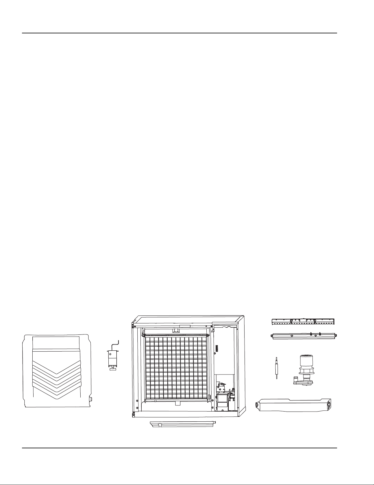
Parts Removal for Cleaning/Sanitizing
Single Evaporator Ice Machines
A. Remove the water curtain
• Gently flex the curtain in the center and remove it
from the right side.
• Slide the left pin out.
B. Remove the ice thickness probe
• Compress the hinge pin on the top of the ice
thickness probe.
• Pivot the ice thickness probe to disengage one pin
then the other. The ice thickness probe can be
cleaned at this point without complete removal. If
complete removal is desired, disconnect the ice
thickness control wiring from the control board.
C. Remove the evaporator tray or water diverter
from the bottom of the evaporator
• Loosen thumbscrew on left side of tray.
• Allow left side of tray to drop as you pull the tray to
the left side. Continue until the outlet tube
disengages from the right side.
D. Remove the water trough
• Depress tabs on right and left side of the water
trough.
• Allow front of water trough to drop as you pull forward
to disengage the rear pins.
E. Remove the water level probe
• Pull the water level probe straight down to
disengage.
• Lower the water level probe until the wiring connector
is visible.
• Disconnect the wire lead from the water level probe.
• Remove the water level probe from the ice machine.
F. Remove the water pump
• Grasp pump and pull straight down on pump
assembly until water pump disengages and electrical
connector is visible.
• Disconnect the electrical connector.
• Remove the water pump assembly from ice machine.
• Do not soak the water pump motor in cleaner or
sanitizer solution.
G. Remove the water distribution tube
NOTE: Distribution tube thumbscrews are retained to
prevent loss. Loosen thumbscrews but do not pull
thumbscrews out of distribution tube.
• Loosen the two outer screws (do not remove screws
completely they are retained to prevent loss) and pull
forward on the distribution tube to release from slip
joint.
• Disassemble distribution tube by loosening the two
(2) middle thumbscrews and dividing the distribution
tube into two pieces.
26
G
E
B
A
C
Part Number 000006520 Rev 03 12/19
D
F
Page 27
Section 4 Maintenance
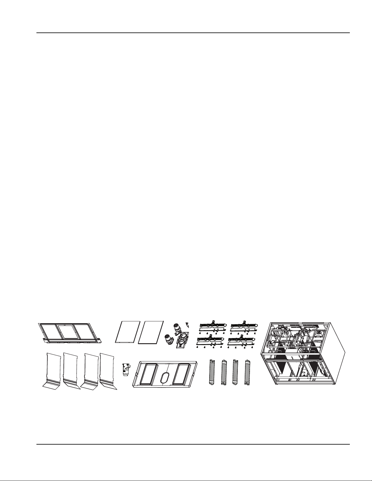
Multiple Evaporator Ice Machines
A. Remove front evaporator shield
• Remove four quarter turn connectors.
• Remove splash shield.
B. Remove left and right evaporator top covers
• Remove two thumbscrews from the front of each
evaporator top cover.
• Lift front of cover, pull forward to remove.
C. Remove splash shields
NOTE: Each evaporator has a splash shield that must
be removed - total of four splash shields.
• Grasp the top center of splash shields.
• Lift up and then out.
D. Remove ice thickness probe
• Compress the hinge pin on the top of the ice
thickness probe.
• Pivot the ice thickness probe to disengage one pin
then the other. The ice thickness probe can be
cleaned at this point without complete removal. If
complete removal is desired, disconnect the ice
thickness control wiring from the control board.
E. Remove the water pump assembly
• Disconnect the vinyl distribution tube from both water
pumps.
• Disconnect the water pump and water level probe
electrical connections.
• After the wires are disconnected remove the two
thumbscrews and lift the water pump assembly out of
the ice machine.
• Remove the thumbscrews securing the water pumps
(2 each pump) and remove water pumps. Do not
immerse the water pump motor in cleaner or sanitizer
solutions.
• Remove the water level probe from the assembly
housing.
F. Remove the water trough
• Pull forward on the water trough to remove.
G. Remove distribution tubes
NOTE: Each evaporator has a distribution that must be
removed - total of four distribution tubes.
• Distribution tube thumbscrews are retained to
prevent loss. Loosen thumbscrews but do not pull
thumbscrews out of distribution tube.
• Loosen the two outer screws and pull forward on the
distribution tube to release from slip joint.
• Disassemble distribution tube by loosening the two
(2) middle thumbscrews and dividing the distribution
tube into two pieces.
H. Remove ice dampers
NOTE: Each evaporator has an ice damper that must be
removed - total of four ice dampers.
• Grasp ice damper and apply pressure toward the
back mounting bracket.
• Apply pressure to the front mounting bracket with
thumb.
• Pull ice damper downward when the front ice damper
pin disengages.
A
D
C
Part Number 000006520 Rev 03 12/19 27
B
E
F
G
H
Page 28
Maintenance Section 4
Exterior Cleaning
Clean the area around the ice machine as often as
necessary to maintain cleanliness and efficient
operation. Use cleaners designed for use with stainless
steel products.
Sponge any dust and dirt off the outside of the ice
machine with mild soap and water. Wipe dry with a
clean, soft cloth.
Heavy stains should be removed with stainless steel
wool. Never use plain steel wool or abrasive pads. They
will scratch the panels.
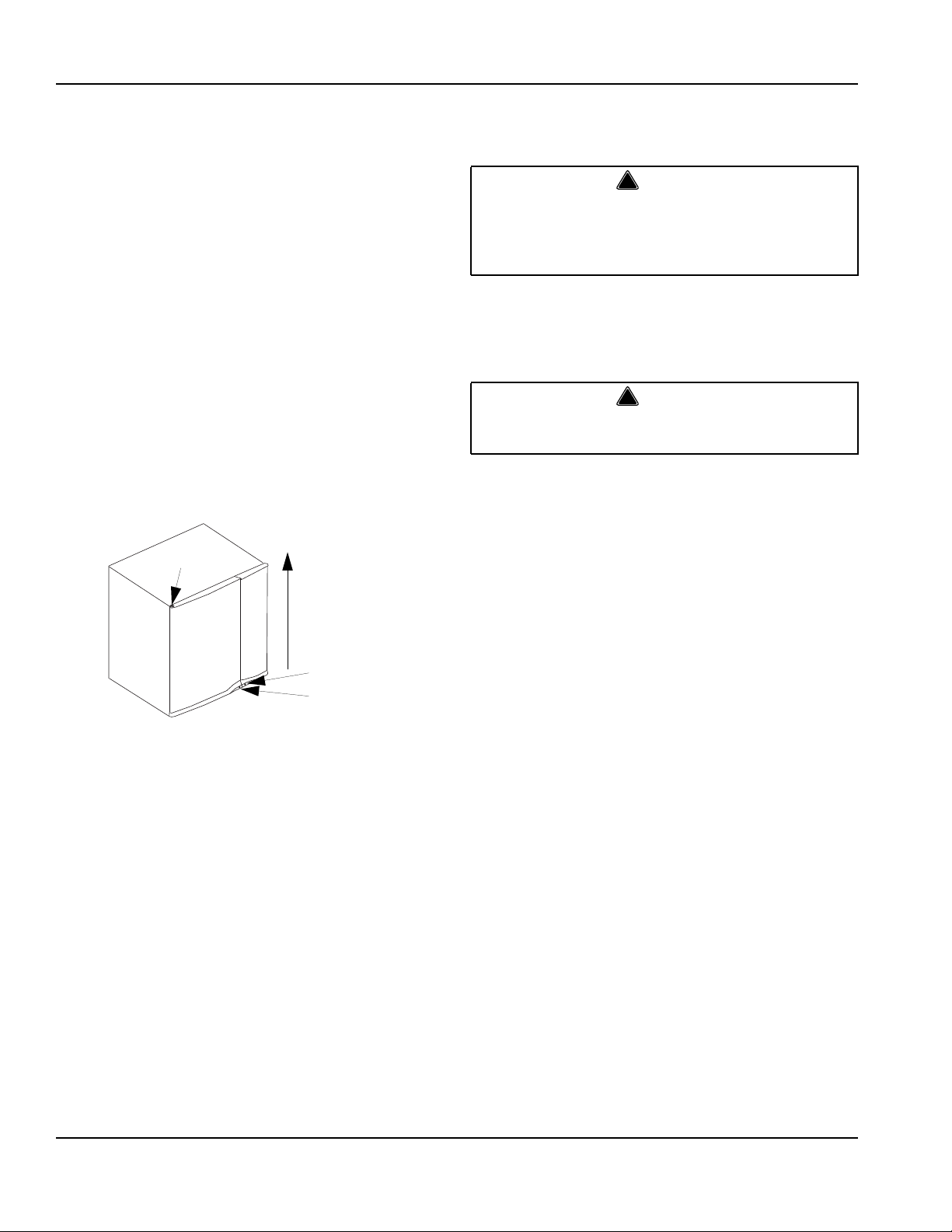
Door Removal
1. Use a phillips screwdriver to loosen the two screws
securing the left and right doors. Do not remove they
are secured to prevent loss.
2. 30 Inch and 48 Inch Models: To remove right front
door lift up and remove (22 inch ice machines have
a single door, lift to remove entire door).
4
2
Cleaning the Condenser
GENERAL
Warning
!
Disconnect electric power to the ice machine head
section and the remote condensing unit at the
electric service switches before cleaning the
condenser.
A dirty condenser restricts airflow, resulting in
excessively high operating temperatures. This reduces
ice production and shortens component life.
• Clean the condenser at least every six months.
Warning
!
The condenser fins are sharp. Use care when
cleaning them.
• Shine a flashlight through the condenser to check for
dirt between the fins.
• Blow compressed air or rinse with water from the
inside out (opposite direction of airflow).
• If dirt still remains call a service agent to clean the
condenser.
Removal from Service/Winterization
1
Door Removal
3. Open left front door to 45 degrees.
4. Support with right hand, depress top pin, tilt top of
door forward and lift out of bottom pin to remove.
1. Clean and sanitize the ice machine.
2. Move the ICE/OFF/CLEAN switch to OFF.
3. Turn off the water supply, disconnect and drain the
incoming ice-making water line at the rear of the ice
machine and drain the water trough.
4. Energize the ice machine, wait one minute for the
water inlet valve to open and blow compressed air in
both the incoming water and the drain openings in
the rear of the ice machine to remove all water.
5. Move ICE/OFF/CLEAN switch to OFF and
disconnect the electric power at the circuit breaker
or the electric service switch.
6. Fill spray bottle with sanitizer and spray all interior
food zone surfaces. Do not rinse and allow to air dry.
7. Replace all panels.
28
Part Number 000006520 Rev 03 12/19
Page 29
Section 5
Customer Support
Checklist
If a problem arises during operation of your ice machine, follow the checklist below before calling service. Routine
adjustments and maintenance procedures are not covered by the warranty.
Problem Possible Cause To Correct
Ice machine does not operate. No electrical power to the ice machine
and/or condensing unit.
High pressure cutout tripping. Clean condenser coil. (See Section 4)
ICE/OFF/CLEAN toggle switch set
improperly.
Water curtain stuck open. Water curtain must be installed and
Remote receiver service valve and/or
Liquid/suction line shut off valves are
closed.
Ice machine stops, and can be restarted
by moving the toggle switch to OFF and
back to ICE.
Ice machine does not release ice or is
slow to harvest.
Ice machine does not cycle into harvest
mode.
Ice quality is poor (soft or not clear). Poor incoming water quality. Contact a qualified service company
Safety limit feature stopping the ice
machine.
Ice machine is dirty. Clean and sanitize the ice machine.
Ice machine is not level. Level the ice machine. (See Section 2)
Low air temperature around ice machine
head section.
Fan cycling control does not de-energize
condenser fan motor.
The six-minute freeze time lock-in has
not expired yet.
Ice thickness probe is dirty. Clean and sanitize the ice machine.
Ice thickness probe is disconnected. Connect the wire.
Ice thickness probe is out of adjustment. Adjust the ice thickness probe.
Uneven ice fill (thin at the top of
evaporator).
Water filtration is poor. Replace the filter.
Ice machine is dirty. Clean and sanitize the ice machine.
Water dump valve is not working. Disassemble and clean the water dump
Water softener is working improperly
(if applicable).
Replace the fuse/reset the breaker/turn
on the main switch.
Move the toggle switch to the ICE
position.
swinging freely. (See Section 4)
Open the valve(s). (See Section 2)
Refer to “Safety Limit Feature” on the
next page.
(See Section 4)
Air temperature must be at least 35°F
(1.6°C).
Verify pressure is below cut-out setpoint,
replace fan cycling control.
Wait for the freeze lock-in to expire.
(See Section 4)
(See Section 3)
Verify sufficient water level in sump
trough. Contact a qualified service
company to check refrigeration system.
to test the quality of the incoming
water and make appropriate filter
recommendations.
(See Section 4)
valve. (See Section 4)
Repair the water softener.
Part Number 000006520 Rev 03 12/19 29
Page 30
Customer Support Section 5
Problem Possible Cause To Correct
Ice machine produces shallow or
incomplete cubes, or the ice fill pattern on
the evaporator is incomplete.
Low ice capacity. Water inlet valve filter screen is dirty. Remove the water inlet valve and clean
Ice thickness probe is out of adjustment. Adjust the ice thickness probe.
(See Section 4)
Water trough level is too low. Check the water level probe for damage.
(See Section 3)
Water inlet valve filter screen is dirty. Remove the water inlet valve and clean
the filter screen. (See Section 4)
Water filtration is poor. Replace the filter.
Hot incoming water. Connect the ice machine to a cold water
supply. (See Section 2)
Water inlet valve is not working. Replace the water inlet valve.
Incorrect incoming water pressure. Water pressure must be 20-80 psi
(1.4 bar - 5.5 bar).
Ice machine is not level. Level the ice machine. (See Section 2)
the filter screen. (See Section 4)
Incoming water supply is shut off. Open the water service valve.
Water inlet valve stuck open or leaking. Place toggle switch in OFF position, if
water continues to enter water trough
replace the water inlet valve.
The condenser is dirty. Clean the condenser. (See Section 4)
High air temperature entering condenser. Air temperature must not exceed 120°F
(39°C).
The harvest assist air compressor is not
functioning.
Call for service.
Safety Limit Feature
In addition to the standard safety controls, such as the
high pressure cutout, your Manitowoc ice machine
features built-in safety limits which will stop the ice
machine if conditions arise which could cause a major
component failure.
Before calling for service, re-start the ice machine using
the following procedure:
1. Move the ICE/OFF/CLEAN switch to OFF and then
back to ICE.
A. If the safety limit feature has stopped the ice
machine, it will restart after a short delay.
Proceed to step 2.
B. If the ice machine does not restart, see “Ice
machine does not operate” on the previous
page.
2. Allow the ice machine to run to determine if the
condition is recurring.
A. If the ice machine stops again, the condition has
recurred. Call for service.
B. If the ice machine continues to run, the condition
has corrected itself. Allow the ice machine to
continue running.
30
Part Number 000006520 Rev 03 12/19
Page 31

Section 5 Customer Support
Commercial Ice Machine Warranty
Manitowoc Ice, Inc. (hereinafter referred to as the “COMPANY”) warrants for a period of thirty-six months from the
installation date (except as limited below) that new ice machines manufactured by the COMPANY shall be free of
defects in material or workmanship under normal and proper use and maintenance as specified by the COMPANY
and upon proper installation and start-up in accordance with the instruction manual supplied with the ice machine.
The COMPANY’s warranty hereunder with respect to the compressor shall apply for an additional twenty-four months,
excluding all labor charges, and with respect to the evaporator for an additional twenty-four months, including labor
charges.
The obligation of the COMPANY under this warranty is limited to the repair or replacement of parts, components, or
assemblies that in the opinion of the COMPANY are defective. This warranty is further limited to the cost of parts,
components or assemblies and standard straight time labor charges at the servicing location.
Time and hourly rate schedules, as published from time to time by the COMPANY, apply to all service procedures.
Additional expenses including without limitation, travel time, overtime premium, material cost, accessing or removal of
the ice machine, or shipping are the responsibility of the owner, along with all maintenance, adjustments, cleaning,
and ice purchases. Labor covered under this warranty must be performed by a COMPANY Contracted Service
Representative or a refrigeration service agency as qualified and authorized by the COMPANY’s local Distributor. The
COMPANY’s liability under this warranty shall in no event be greater than the actual purchase price paid by customer
for the ice machine.
The foregoing warranty shall not apply to (1) any part or assembly that has been altered, modified, or changed; (2)
any part or assembly that has been subjected to misuse, abuse, neglect, or accidents; (3) any ice machine that has
been installed and/or maintained inconsistent with the technical instructions provided by the COMPANY; or (4) any ice
machine initially installed more than five years from the serial number production date. This warranty shall not apply if
the Ice Machine’s refrigeration system is modified with a condenser, heat reclaim device, or parts and assemblies
other than those manufactured by the COMPANY, unless the COMPANY approves these modifications for specific
locations in writing.
THIS WARRANTY IS IN LIEU OF ALL OTHER WARRANTIES OR GUARANTEES OF ANY KIND, EXPRESSED
OR IMPLIED, INCLUDING ANY IMPLIED WARRANTY OF MERCHANTABILITY OR FITNESS FOR A
PARTICULAR PURPOSE. In no event shall the COMPANY be liable for any special, indirect, incidental or
consequential damages. Upon the expiration of the warranty period, the COMPANY’s liability under this warranty shall
terminate. The foregoing warranty shall constitute the sole liability of the COMPANY and the exclusive remedy of the
customer or user.
To secure prompt and continuing warranty service, the warranty registration card must be completed and sent to the
COMPANY within five (5) days from the installation date.
Complete the following and retain for your record:
Distributor/Dealer ______________________________________________________________________________
Model Number ________________________________ Serial Number __________________________________
Installation Date _______________________________________________________________________________
MANITOWOC ICE, INC.
2110 So. 26th St., P.O. Box 1720, Manitowoc, WI 54221-1720
Telephone: 920-682-0161 Fax: 920-683-7585
Web Site - www.manitowocice.com
Form 80-0375-3 Rev. 01-02
Part Number 000006520 Rev 03 12/19 31
Page 32

Customer Support Section 5
Residential Ice Machine Limited Warranty
WHAT DOES THIS LIMITED WARRANTY COVER?
Subject to the exclusions and limitations below, Manitowoc
Foodservice (“Manitowoc”) warrants to the original consumer
that any new ice machine manufactured by Manitowoc (the
“Product”) shall be free of defects in material or workmanship
for the warranty period outlined below under normal use and
maintenance, and upon proper installation and start-up in
accordance with the instruction manual supplied with the
Product.
HOW LONG DOES THIS LIMITED WARRANTY LAST?
Product Covered Warranty Period
Ice Machine Twelve (12) months
from the sale date
WHO IS COVERED BY THIS LIMITED WARRANTY?
This limited warranty only applies to the original consumer of
the Product and is not transferable.
WHAT ARE MANITOWOC ICE’S OBLIGATIONS UNDER
THIS LIMITED WARRANTY?
If a defect arises and Manitowoc receives a valid warranty
claim prior to the expiration of the warranty period, Manitowoc
shall, at its option: (1) repair the Product at Manitowoc’s cost,
including standard straight time labor charges, (2) replace the
Product with one that is new or at least as functionally
equivalent as the original, or (3) refund the purchase price for
the Product. Replacement parts are warranted for 90 days or
the balance of the original warranty period, whichever is
longer. The foregoing constitutes Manitowoc’s sole obligation
and the consumer’s exclusive remedy for any breach of this
limited warranty. Manitowoc’s liability under this limited
warranty is limited to the purchase price of Product. Additional
expenses including, without limitation, service travel time,
overtime or premium labor charges, accessing or removing
the Product, or shipping are the responsibility of the
consumer.
WHAT IS NOT COVERED?
This limited warranty does not cover, and you are solely
responsible for the costs of: (1) periodic or routine
maintenance, (2) repair or replacement of the Product or parts
due to normal wear and tear, (3) defects or damage to the
Product or parts resulting from misuse, abuse, neglect, or
accidents, (4) defects or damage to the Product or parts
resulting from improper or unauthorized alterations,
modifications, or changes; and (5) defects or damage to any
Product that has not been installed and/or maintained in
accordance with the instruction manual or technical
instructions provided by Manitowoc. To the extent that
warranty exclusions are not permitted under some state laws,
these exclusions may not apply to you.
E
XCEPT AS STATED IN THE FOLLOWING SENTENCE, THIS LIMITED
WARRANTY IS THE SOLE AND EXCLUSIVE WARRANTY OF
MANITOWOC WITH REGARD TO THE PRODUCT. ALL IMPLIED
WARRANTIES ARE STRICTLY LIMITED TO THE DURATION OF THE
LIMITED WARRANTY APPLICABLE TO THE PRODUCTS AS STATED
ABOVE, INCLUDING BUT NOT LIMITED TO, ANY WARRANTY OF
MERCHANTABILITY OR OF FITNESS FOR A PARTICULAR
PURPOSE.
Some states do not allow limitations on how long an implied
warranty lasts, so the above limitation may not apply to you.
I
N NO EVENT SHALL MANITOWOC OR ANY OF ITS AFFILIATES BE
LIABLE TO THE CONSUMER OR ANY OTHER PERSON FOR ANY
INCIDENTAL, CONSEQUENTIAL OR SPECIAL DAMAGES OF ANY
KIND (INCLUDING, WITHOUT LIMITATION, LOSS PROFITS,
R
EVENUE OR BUSINESS) ARISING FROM OR IN ANY MANNER
CONNECTED WITH THE PRODUCT, ANY BREACH OF THIS LIMITED
WARRANTY, OR ANY OTHER CAUSE WHATSOEVER, WHETHER
BASED ON CONTRACT, TORT OR ANY OTHER THEORY OF
LIABILITY.
Some states do not allow the exclusion or limitation of
incidental or consequential damages, so the above limitation
or exclusion may not apply to you.
HOW TO OBTAIN WARRANTY SERVICE
To obtain warranty service or information regarding your
Product, please contact us at:
MANITOWOC FOODSERVICE
2110 So. 26th St.
P.O. Box 1720,
Manitowoc, WI 54221-1720
Telephone: 920-682-0161 Fax: 920-683-7585
www.manitowocice.com
32
HOW STATE LAW APPLIES
This limited warranty gives you specific legal rights, and you
may also have rights that vary from state to state or from one
jurisdiction to another.
REGISTRATION CARD
To secure prompt and continuing warranty service, this
warranty registration card must be completed and sent to
Manitowoc within thirty (30) days from the sale date. Complete
the following registration card and send it to Manitowoc.
Part Number 000006520 Rev 03 12/19
Page 33

Page 34

Page 35

Page 36

Manitowoc Ice
2110 South 26th Street Manitowoc, WI
54220
800-545-5720
www.manitowocice.com
© 2019 Manitowoc Ice except where explicitly stated otherwise. All rights reserved.
Part Number 000006520 Rev 03 12/19
 Loading...