

Page 1
Technician’s
Handbook
Manitowoc
This manual is updated as new information and models are
released. Visit our website for the latest manual.
www.manitowocice.com
America’s #1 Selling Ice Machine
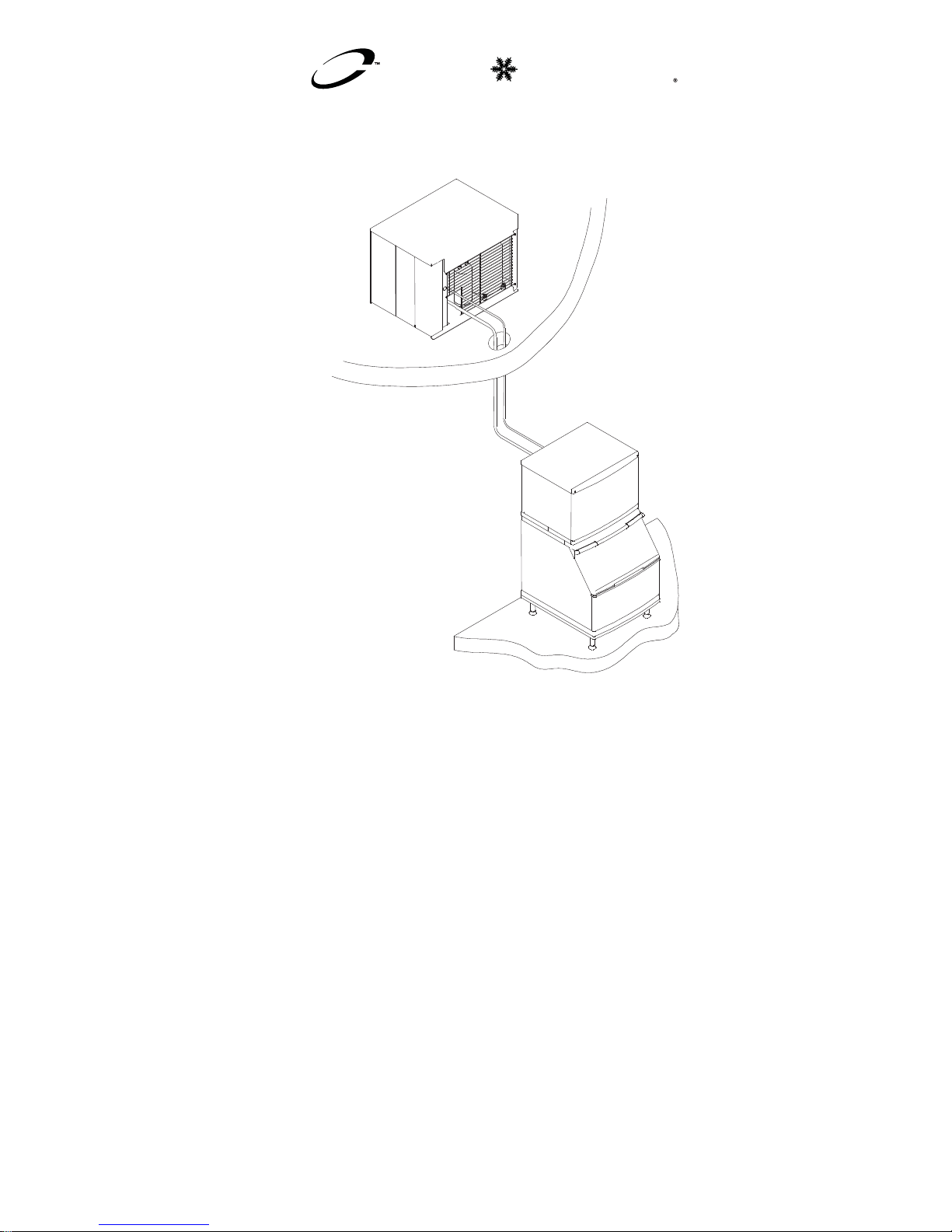
S Model & Ice Beverage
QuietQube
®
Ice Machines
Part Number 80-1505-3 6/11
Page 2

Page 3
Safety Notices
As you work on Manitowoc equipment, be sure to pay
close attention to the safety notices in this handbook.
Disregarding the notices may lead to serious injury
and/or damage to the equipment.
Throughout this handbook, you will see the following
types of safety notices:
Procedural Notices
As you work on Manitowoc equipment, be sure to read
the procedural notices in this handbook. These notices
supply helpful information which may assist you as
you work.
Throughout this handbook, you will see the following
types of procedural notices:
!
Warning
Text in a Warning box alerts you to a potential
personal injury situation. Be sure to read the
Warning statement before proceeding, and work
carefully.
!
Caution
Text in a Caution box alerts you to a situation in
which you could damage the equ ipment. Be sure
to read the Caution statement before proceeding,
and work carefully.
Important
Text in an Important box provides you with
information that may help you perform a
procedure more efficiently. Disregarding this
information will not cause damage or injury, but it
may slow you down as you work.
Page 4
NOTE: Text set off as a Note provides you with simple,
but useful, extra information about the procedure you
are performing.
Read These Before Proceeding:
!
Caution
Proper installation, care and maintenance are
essential for maximum performance and troublefree operation of your Manitowoc equipment. If
you encounter problems not covered by this
handbook, do not proceed, contact Manitowoc
Foodservice Group. We will be happy to provide
assistance.
Important
Routine adjustments and maintenance
procedures outlined in this handbook are not
covered by the warranty.
! Warning
PERSONAL INJURY POTENTIAL
Do not operate equipment that has been
misused, abused, neglected, damaged, or
altered/modified from that of original
manufactured specifications.
We reserve the right to make prod uct
improvements at any time. Specifications and
design are subject to change without notice.
Page 5

Part Number 80-1505-3 6/11 5
Table of Contents
General Information
Model Numbers . . . . . . . . . . . . . . . . . .13
How to Read a Model Number . . . . . .14
Ice Cube Sizes . . . . . . . . . . . . . . . . . .15
Model/Serial Number Location . . . . . .16
Energy Efficient Ice Machine
Serial Breaks . . . . . . . . . . . . . . . . . . . .16
Ice Machine Warranty Information . . . 17
Installation
Location of Ice Machine . . . . . . . . . . .23
Ice Machine Head Section
Clearance Requirements . . . . . . . . . . .24
Stacking Two Ice Machines on a
Single Storage Bin . . . . . . . . . . . . . . .25
Ice Deflector . . . . . . . . . . . . . . . . . . . .25
Removing the Front Panels . . . . . . . . . 26
Location of CVD
®
Condensing Unit . . .27
Condensing Unit Clearance
Requirements . . . . . . . . . . . . . . . . . . .28
Bin Installation . . . . . . . . . . . . . . . . . . .29
S1470C/S1870C/S2070C/S2170C
Installation on a Manitowoc Bin . . . . . .31
Ice Machine on a Dispenser Installation 33
Ice Machine Head Section Water
Supply and Drains . . . . . . . . . . . . . . . .36
Water Cooled Condenser Water Supply
and Drains . . . . . . . . . . . . . . . . . . . . . .38
Electrical Requirements . . . . . . . . . . .39
Refrigeration System Installation . . . . .41
Page 6

6 Part Number 80-1505-3 6/11
Operational Checks . . . . . . . . . . . . . . . . . 61
General . . . . . . . . . . . . . . . . . . . . . . . . 61
Water Level . . . . . . . . . . . . . . . . . . . . 61
Ice Thickness Check . . . . . . . . . . . . . 62
Harvest Sequence Water Purge . . . . . 63
Electronic Bin Thermostat Instructions
IB600C/IB680C/IB800C/IB1000C Only
Positioning . . . . . . . . . . . . . . . . . . . . . 64
Component Identification
Ice Machine Head Sections . . . . . . . . 67
CVD
®
Condensing Units . . . . . . . . . . . 71
Maintenance
General . . . . . . . . . . . . . . . . . . . . . . . . . . . 73
Cleaning / Sanitizing Procedure . . . . . . . 74
Cleaning Procedure . . . . . . . . . . . . . . 74
Parts Removal for Cleaning/Sanitizi ng 76
Sanitizing Procedure . . . . . . . . . . . . . 83
Procedure to Clean He av il y Scaled
Ice Machines . . . . . . . . . . . . . . . . . . . . . . 85
General . . . . . . . . . . . . . . . . . . . . . . . . 85
Cleaning Procedure . . . . . . . . . . . . . . 85
Parts Removal for Cleaning/Sanitizi ng 88
Sanitizing Procedure . . . . . . . . . . . . . 102
Additional Component Removal . . . . . 104
Removal from Service/Winterization . . . 109
General . . . . . . . . . . . . . . . . . . . . . . . . 109
CVD1486 Water Cooled Condensing Unit
. . . . . . . . . . . . . . . . . . . . . . . . . . . . . . 110
Sequence of Operation
Initial Start-Up or Start-Up After
Automatic Shut-Off . . . . . . . . . . . . . . . 111
Freeze Sequence . . . . . . . . . . . . . . . . 113
Harvest Sequence . . . . . . . . . . . . . . . 114
Automatic Shut-Off . . . . . . . . . . . . . . . 117
Page 7

Part Number 80-1505-3 6/11 7
Troubleshooting
Safety Limits . . . . . . . . . . . . . . . . . . . . . . .123
Safety Limit Analysis . . . . . . . . . . . . . .125
Safety Limit#1 . . . . . . . . . . . . . . . . . . .126
Safety Limit #2 . . . . . . . . . . . . . . . . . .127
Safety Limit #3 . . . . . . . . . . . . . . . . . .128
Control Board Testing . . . . . . . . . . . . . . .129
Control Board Test Cycle . . . . . . . . . .129
Troubleshooting By Symptom . . . . . . . .130
Symptom #1 Ice Machine Will Not Run .131
Diagnosing an Ice Machine Head Section
that Will Not Run . . . . . . . . . . . . . . . . .133
Diagnosing a Condensing Unit
That Will Not Run . . . . . . . . . . . . . . . .134
Compressor Electrical Diagnostics . . .135
Symptom #2 Low Production, Long Freeze
Cycle . . . . . . . . . . . . . . . . . . . . . . . . . . . . .138
Symptom #2 - Refrigeration System Opera-
tional Analysis Tables . . . . . . . . . . . . . 140
Symptom #2 - Freeze Cycle Refrigeration
System Operational Analysis Table Proce-
dures . . . . . . . . . . . . . . . . . . . . . . . . . .149
Symptom #3 Ice Will Not Harvest . . . . . .166
Ice Machine will Not Harvest Diagnostics
. . . . . . . . . . . . . . . . . . . . . . . . . . . . . . .166
Harvest Problems . . . . . . . . . . . . . . . .167
Symptom #3 Ice Will Not Harvest, Cubes Are
Not Melted Flowchart . . . . . . . . . . . . . . . .168
Symptom #4 Ice Will not Harvest - Cubes Are
Melted Flowchart . . . . . . . . . . . . . . . . . . .172
Page 8

8 Part Number 80-1505-3 6/11
Component Check Procedures
Electrical Components . . . . . . . . . . . . . . 175
Main Fuse . . . . . . . . . . . . . . . . . . . . . . 175
Bin Switch . . . . . . . . . . . . . . . . . . . . . . 176
Harvest Assist Air Pump . . . . . . . . . . . 179
ICE/OFF/CLEAN Toggle Switch . . . . . 180
Ice Thickness Probe (Harvest Initia tion )
. . . . . . . . . . . . . . . . . . . . . . . . . . . . . . 182
Water Level Control Circuitry . . . . . . . 187
Electronic Bin Thermostat Control . . . 193
Compressor Electrical Diagnostics . . . 199
Diagnosing Start Components . . . . . . 201
Refrigeration Components . . . . . . . . . . . 204
Refrigerant Charge Verification . . . . . 204
Suction Accumulator Operation . . . . . 206
Headmaster Control Valve . . . . . . . . . 207
Headmaster Valve Water-Cooled Condens-
ing Unit - CVD1476 . . . . . . . . . . . . . . . 212
Water Regulating Valve CVD1476 . . . 214
Fan Cycle Control . . . . . . . . . . . . . . . . 215
High Pressure Cutout (HPCO) Control 216
Low Pressure Cutout (LPCO) Control 217
Refrigerant Recovery/Evacuation . . . . . 218
Connections . . . . . . . . . . . . . . . . . . . . 219
Recovery/Evacuation Procedures . . . 221
Charging Procedures . . . . . . . . . . . . . 222
System Contamination Cleanup . . . . . . . 223
Determining Severity of Contamination 223
Cleanup Procedure . . . . . . . . . . . . . . 225
Refrigerant Reuse Policy . . . . . . . . . . . . 230
Page 9

Part Number 80-1505-3 6/11 9
Component Specifications
Main Fuse . . . . . . . . . . . . . . . . . . . . . .233
Bin Switch . . . . . . . . . . . . . . . . . . . . . .233
Harvest Assist Air Pump . . . . . . . . . . .233
ICE/OFF/CLEAN Toggle Switch . . . . .233
Electronic Bin Thermostat Control . . . .233
Water Regulating Valve . . . . . . . . . . .233
Fan Cycle Control . . . . . . . . . . . . . . . .234
High Pressure Cutout (HPCO) Control 234
Low Pressure Cutout (LPCO) Control . 234
Filter-Driers . . . . . . . . . . . . . . . . . . . . .235
Total System Refrigerant Charge . . . .237
Charts
Cycle Times/24-Hour Ice Production/Refriger-
ant Pressure . . . . . . . . . . . . . . . . . . . . . . .239
S0600C/CVD0675 Series Remote Air
Cooled . . . . . . . . . . . . . . . . . . . . . . . . .240
SD0682C/CVD0685 Series Remote Air
Cooled . . . . . . . . . . . . . . . . . . . . . . . . .241
SY0684C/CVD0685 Series Remote Air
Cooled . . . . . . . . . . . . . . . . . . . . . . . . .242
IB0600C/CVD675 Series Remote Air
Cooled . . . . . . . . . . . . . . . . . . . . . . . . .243
IB0682DC/CVD685 Series Remote Air
Cooled . . . . . . . . . . . . . . . . . . . . . . . . .244
IB0684YC/CVD685 Series Remote Air
Cooled . . . . . . . . . . . . . . . . . . . . . . . . .245
SD0872C/SY0874C/CVD0885 Series
Remote Air Cooled Machines Before Serial
Number 110682385 . . . . . . . . . . . . . .246
SD0872C/CVD0885 Series Remote Air
Cooled Machines After Serial Number
110682385 . . . . . . . . . . . . . . . . . . . . .247
SY0874C/CVD0885 Series Remote Air
Cooled Machines After Serial Number
110682385 . . . . . . . . . . . . . . . . . . . . .248
IB0822DC/IB0824YC/CVD885 Series Remote Air Cooled Machines Before Serial
Number 110682385 . . . . . . . . . . . . . .249
Page 10

10 Part Number 80-1505-3 6/11
IB0822DC/CVD885 Series Remote Air
Cooled Machines After Serial Number
110682385 . . . . . . . . . . . . . . . . . . . . . 250
IB0824YC/CVD885 Series Remote Air
Cooled Machines After Serial Number
110682385 . . . . . . . . . . . . . . . . . . . . . 251
SD1072C/SY1074C/CVD1085 Series Remote Air Cooled Machines Before Serial
Number 110697654 . . . . . . . . . . . . . . 252
SD1072C/CVD1085 Series Remote Air
Cooled Machines After Serial Number
110697654 . . . . . . . . . . . . . . . . . . . . . 253
SY1074C/CVD1085 Series Remote Air
Cooled Machines After Serial Number
110697654 . . . . . . . . . . . . . . . . . . . . . 254
IB1022DC/IB1024YC/CVD1075/CVD1085/
CVD1285 Series Remote Air Cooled
Machines Before Serial Number 110697294
. . . . . . . . . . . . . . . . . . . . . . . . . . . . . . 255
IB1022DC/CVD1185 Series Remote Air
Cooled Machines After Serial Number
110697294 . . . . . . . . . . . . . . . . . . . . . 256
IB1024YC/CVD1185 Series Remote Air
Cooled Machines After Serial Number
110697294 . . . . . . . . . . . . . . . . . . . . . 257
SD1272C/SY1274C/CVD1285 Series Remote Air Cooled Machines Before Serial
Number 110706336 . . . . . . . . . . . . . . 258
SD1272C/CVD1285 Series Remote Air
Cooled Machines After Serial Number
110706336 . . . . . . . . . . . . . . . . . . . . . 259
SY1274C/CVD1285 Series Remote Air
Cooled Machines After Serial Number
110706336 . . . . . . . . . . . . . . . . . . . . . 260
S1470C/CVD1485 Series Remote Air
Cooled . . . . . . . . . . . . . . . . . . . . . . . . 261
S1470C/CVD1486 Remote Water Cooled
262
SD1872C/CVD1885 Series Remote Air
Cooled . . . . . . . . . . . . . . . . . . . . . . . . 263
Page 11

Part Number 80-1505-3 6/11 11
SY1874C/CVD1885 Series Remote Air
Cooled . . . . . . . . . . . . . . . . . . . . . . . . .264
SD2072C/CVD2075 Series Remote Air
Cooled . . . . . . . . . . . . . . . . . . . . . . . . .265
SY2074C/CVD2075 Series Remote Air
Cooled . . . . . . . . . . . . . . . . . . . . . . . . .266
SD2172C/CVD2085 Series Remote Air
Cooled . . . . . . . . . . . . . . . . . . . . . . . . .267
SY2174C/CVD2085 Series Remote Air
Cooled . . . . . . . . . . . . . . . . . . . . . . . . .268
SD3072C/CVD3085 Series Remote Air
Cooled . . . . . . . . . . . . . . . . . . . . . . . . .269
SY3074C/CVD3085 Series Remote Air
Cooled . . . . . . . . . . . . . . . . . . . . . . . . .270
Diagrams
Wiring Diagrams . . . . . . . . . . . . . . . . . . . .271
Wiring Diagram Legend . . . . . . . . . . . .271
S600C/S850C/1000C/S1200C . . . . . .272
S600C/S680C/S850C/1000C/S1200C 273
S1470C/S1870C/S2070C/S2170C . . .274
S3070C 115/60/1 . . . . . . . . . . . . . . . .275
S3070C 230V/50Hz/1Ph . . . . . . . . . .276
IB0600C/IB0800C/IB1000C with S Control
Board and Electronic Bin Thermostat .277
IB0600C/IB0680C/IB0800C/IB1000C
with Air Assist/S Control Board/Electronic
Bin Thermostat . . . . . . . . . . . . . . . . . .278
CVD675/CVD685/CVD885/CVD1075/
CVD1085/CVD1185/CVD1285/CVD1485/
CVD1486/CVD1885/CVD2075/CVD3085 -
1 Phase . . . . . . . . . . . . . . . . . . . . . . . .279
CVD2085 without PTCR- 1 Phase . . .280
CVD2085 with PTCR- 1 Phase . . . . . .281
CVD675/CVD685/CVD885/CVD1075/
CVD1085/CVD1185/CVD1285/CVD1485/
CVD1486/CVD1885/CVD2075/CVD2085/
CVD3085 - 3 Phase . . . . . . . . . . . . . .282
CVD3085 380V/50hz/3ph . . . . . . . . . .283
Page 12

12 Part Number 80-1505-3 6/11
Electronic Control Board . . . . . . . . . . . . 284
Single and Twin Evaporator Models . . 284
Quad Evaporator Models . . . . . . . . . . 286
Refrigeration Tubing Sche matics . . . . . 287
S600C/S680C/S850C/S1000C/S1200C
. . . . . . . . . . . . . . . . . . . . . . . . . . . . . . 287
S600C/S680C/S850C/S1000C/S1200C
. . . . . . . . . . . . . . . . . . . . . . . . . . . . . . 288
Ice Beverage IB0600C/IB0680C/IB0800C/
IB1000C . . . . . . . . . . . . . . . . . . . . . . . 289
Ice Beverage IB0600C/IB0680C/IB0800C/
IB1000C . . . . . . . . . . . . . . . . . . . . . . . 290
S1470C/S1870C/S2070C/S2170C . . . 291
S1470C/S1870C/S2070C/S2170C . . . 292
S1476C Water-Cooled Condenser . . . 293
S3070C Without Check Valve . . . . . . 294
S3070C With Check Valve . . . . . . . . . 295
Page 13

Part Number 80-1505-3 6/11 13
General Information
MODEL NUMBERS
This manual covers the following models:
Ice Machine Head
Section
CVD Condensing Unit*
SD0672C
SY0674C
IB0624YC
IB0622DC
CVD0675
SD0682C
SY0684C
IB0684YC
IB0682DC
CVD0685
SD0872C
SY0874C
IB0824YC
IB0822DC
CVD0885
SD1072C
SY1074C
CVD1085
IB1024YC
IB1022DC
CVD1185
CVD1285
CVD1085
CVD1075
SD1272C
SY1274C
CVD1285
SD1472C
SY1474C
CVD1485
CVD1486
SD1872C
SY1874C
CVD1885
SD2072C
SY2074C
CVD2075
SD2172C
SY2174C
CVD2085
SD3072C
SY3074C
CVD3085
*For 3 phase electrical option: add the number “3”
to end of model number (CVD10853).
Page 14
14 Part Number 80-1505-3 6/11
HOW TO READ A MODEL NUMBER
Head Section
Condensing Unit
S Y 1074 C 3
ICE MACHINE
MODEL
ICE CUBE SIZE
D DICE
Y HALF DICE
# CUBE SIZE
2 DICE
3 DICE
4 HALF-DICE
5 HALF-DICE
CONDENSER TYPE
AIR-COOLED
WATER-COOLED
AIR-COOLED
WATER-COOLED
AY
Y SELF-CONTAINED AIR-COOLED
WY Y SELF-CONTAINED WATER-COOLED
CY Y CVD REMOTE AIR or WATER-COOLED
DC CVD REMOTE AIR-COOLED - DICE
YC CVD REMOTE AIR-COOLED - HALF DICE
7 CVD REMOTE
AIR-COOLED
CONDENSER TYPE
ICE MACHINE
SERIES
ADDITIONAL SPECS
3 3 PHASE
SI INCLUDES
AuCS SI BUILT IN
CVD 1485 3
CONDENSING
UNIT MODEL
3 PHASE
CONDENSING
UNIT SERIES
5 AIR-COOLED
6 WATER-COOLED
Page 15
Part Number 80-1505-3 6/11 15
ICE CUBE SIZES
Dice
7/8" x 7/8" x 7/8"
2.22 x 2.22 x2.22 cm
Half Dice
3/8" x 1-1/8" x 7/8"
0.95 x 2.86 x 2.22 cm
! Warning
Do not operate equipment that has been
misused, abused, neglected, damaged, or
altered/modified from that of original
manufactured specifications.
This appliance is not intended for use by
persons (including children) with reduced
physical, sensory or mental capabilities, or lack
of experience and knowledge, unless they
have been given supervision concer nin g use of
the appliance by a person responsible for their
safety.
! Warning
All Manitowoc ice machines require the ice
storage system (bin, dispenser, etc.) to
incorporate an ice deflector.
Prior to using a non-Manitowoc ice storage
system with other Manitowoc ice machines,
contact the manufacturer to assure their ice
deflector is compatible with Manitowoc ice
machines.
Page 16

16 Part Number 80-1505-3 6/11
MODEL/SERIAL NUMBER LOCATION
These numbers are required when requesting
information from your local Manitowoc Distributor,
service representative, or Manitowoc Ice, Inc. The
model and serial number are listed on the OWNER
WARRANTY REGISTRATION CARD. They are also
listed on the MODEL/SERIAL NUMBER DECAL
affixed to the ice machine.
ENERGY EFFICIENT ICE MACHINE
SERIAL BREAKS
Some specifications have changed since our release
of Energy Efficient machines. The following machines
have a serial break to indicate when they became
Energy Efficient.
Series Ice
Machine
Serial Break for Energy
Efficient Machines
S850C 110682385
S1000C 110697654
S1200C 110706336
IB800C 110682385
IB1000C 110697294
CVD885 110673885
Page 17

Part Number 80-1505-3 6/11 17
ICE MACHINE WARRANTY INFORMATION
Owner Warranty Registration Card
Warranty coverage begins the day the ice machine is
installed.
If the OWNER WARRANTY REGISTRATION CARD is
not returned, Manitowoc will use the date of sale to the
Manitowoc Distributor as the first day of warranty
coverage for your new ice machine.
Important
Complete and mail the OWNER WARRANTY
REGISTRATION CARD as soon as possible to
validate the installation date.
Page 18

18 Part Number 80-1505-3 6/11
Commercial Warranty Coverage
GENERAL
The following Warranty outline is provided for your
convenience. For a detailed explanation, read the
warranty bond shipped with each product.
Contact your local Manitowoc representative or
Manitowoc Ice if you need further warranty
information.
PARTS
1. Manitowoc warrants the ice machine against
defects in materials and workmanship, under
normal use and service for three (3) years from
the date of original installation.
2. The evaporator and compressor are covered by
an additional two (2) year (five years total)
warranty beginning on the date of the original
installation.
LABOR
1. Labor required to repair or replace defective
components is covered for three (3) years from
the date of original installation.
2. The evaporator is covered by an additional
two (2) year (five years total) labor warranty
beginning on the date of the original installation.
Page 19

Part Number 80-1505-3 6/11 19
EXCLUSIONS
The following items are not included in the ice
machine’s warranty coverage:
1. Normal maintenance, adjustments and cleaning
as outlined in this manual.
2. Repairs due to unauthorized modifications to the
ice machine or use of non-standard parts without
prior written approval from Manitowoc Ice
3. Damage caused by improper installation of the ice
machine, electrical supply, water supply or
drainage, or damage caused by floods, storms, or
other acts of God.
4. Premium labor rates due to holidays, overtime,
etc.; travel time; flat rate service call charges;
mileage and miscellaneous tools and material
charges not listed on the payment schedule.
Additional labor charges resulting from the
inaccessibility of equipment are also excluded.
5. Parts or assemblies subjected to misuse, abuse,
neglect or accidents.
6. Damage or problems caused by installation,
cleaning and/or maintenance procedures
inconsistent with the technical instructions
provided in this manual.
AUTHORIZED WARRANTY SERVICE
To comply with the provisions of the warranty, a
refrigeration service company qualified and authorized
by your Manitowoc Distributor, or a Contracted Service
Representative must perform the warranty repair.
SERVICE CALLS
Normal maintenance, adjustments and cleaning as
outlined in this manual are not covered by the
warranty. If you have followed the procedures listed in
this manual, and the ice machine still does not perform
properly, call your Local Distribu to r or the Service
Department at Manitowoc Ice.
Page 20

20 Part Number 80-1505-3 6/11
RESIDENTIAL ICE MACHINE LIMITED WARRANTY
WHAT DOES THIS LIMITED WARRANTY COVER?
Subject to the exclusions and limitations below,
Manitowoc Ice (“Manitowoc”) warrants to the original
consumer that any new ice machine manufactured by
Manitowoc (the “Product”) shall be free of defects in
material or workmanship for the warranty period
outlined below under normal use and maintenance,
and upon proper installation and start-up in
accordance with the instruction manual supplied with
the Product.
HOW LONG DOES THIS LIMITED WARRANTY
LAST?
WHO IS COVERED BY THIS LIMITED WARRANTY?
This limited warranty only applies to the original
consumer of the Product and is not transferable.
WHAT ARE MANITOWOC ICE’S OBLIGATIONS
UNDER THIS LIMITED WARRANTY?
If a defect arises and Manitowoc receives a valid
warranty claim prior to the expiration of the warranty
period, Manitowoc shall, at its option: (1) repair the
Product at Manitowoc’s cost, including standard
straight time labor charges, (2) replace the Product
with one that is new or at least as functionally
equivalent as the original, or (3) refund the purchase
price for the Product. Replacement parts are
warranted for 90 days or the balance of the original
warranty period, whichever is longer. The foregoing
constitutes Manitowoc’s sole obligation and the
consumer’s exclusive remedy for any breach of this
limited warranty . Manitowoc’s liability under this limited
warranty is limited to the purchase price of Product.
Additional expenses including, without limitation,
service travel time, overtime or premium labor
charges, accessing or removing the Product, or
shipping are the responsibility of the consumer.
Product Covered Warranty Period
Ice Machine
Twelve months from the
sale date
Page 21

Part Number 80-1505-3 6/11 21
HOW TO OBTAIN WARRANTY SERVICE
To obtain warranty service or information regarding
your Product, please contact us at:
MANITOWOC ICE
2110 So. 26 th St.
P.O. Box 1720,
Manitowoc, WI 54221-1720
Telephone: 920-682-0161 Fax: 920-683-7585
www.manitowocice.com
WHAT IS NOT COVERED?
This limited warranty does not cover, and you are
solely responsible for the costs of: (1) periodic or
routine maintenance, (2) repair or replacement of the
Product or parts due to normal wear and tear, (3)
defects or damage to the Product or parts resulting
from misuse, abuse, neglect, or accidents, (4) defects
or damage to the Product or parts resulting from
improper or unauthorized alterations, modifications, or
changes; and (5) defects or damage to any Product
that has not been installed and/or maintained in
accordance with the instruction manual or technical
instructions provided by Manitowoc. To the extent that
warranty exclusions are not permitted under some
state laws, these exclusions may not apply to you.
E
XCEPT AS STATED IN THE FOLLOWING SENTENCE, THIS
L
IMITED WARRANTY IS THE SOLE AND EXCLUSIVE
W
ARRANTY OF MANITOWOC WITH REGARD TO THE
P
RODUCT. ALL IMPLIED WARRANTIES ARE STRICTLY
L
IMITED TO THE DURATION OF THE LIMITED WARRANTY
A
PPLICABLE TO THE PRODUCTS AS STATED ABOVE,
I
NCLUDING BUT NOT LIMITED TO, ANY WARRANTY OF
M
ERCHANTABILITY OR OF FITNESS FOR A PARTICULAR
P
URPOSE.
Some states do not allow limitations on how long an
implied warranty lasts, so the above limitation may not
apply to you.
Page 22

22 Part Number 80-1505-3 6/11
IN NO EVENT SHALL MANITOWOC OR ANY OF ITS
A
FFILIATES BE LIABLE TO THE CONSUMER OR ANY
O
THER PERSON FOR ANY INCIDENTAL, CONSEQUENTIAL
O
R SPECIAL DAMAGES OF ANY KIND (INCLUDING,
W
ITHOUT LIMITATION, LOSS OF PROFITS, REVENUE OR
B
USINESS) ARISING FROM OR IN ANY MANNER
C
ONNECTED WITH THE PRODUCT, ANY BREACH OF THIS
L
IMITED WARRANTY, OR ANY OTHER CAUSE
W
HATSOEVER, WHETHER BASED ON CONTRACT, TORT
O
R ANY OTHER THEORY OF LIABILITY.
Some states do not allow the exclusion or limitation of
incidental or consequential damages, so the above
limitation or exclusion may not apply to you.
HOW STATE LAW APPLIES
This limited warranty gives you specific legal rights,
and you may also have rights that vary from state to
state or from one jurisdiction to another.
REGISTRATION CARD
To secure prompt and continuing warranty service, this
warranty registration card must be completed and sent
to Manitowoc within thirty (30) days from the sale date.
Complete the registration card and send it to
Manitowoc.
Page 23

Part Number 80-1505-3 6/11 23
Installation
LOCATION OF ICE MACHINE
S600C/S680C/S850C/S1000C/S1200C/S1470C/
S1870C/S2070C/S2170C/S3070C
The location selected for the ice machine head section
must meet the following criteria. If any of these criteria
are not met, select another location.
• The location must be free of airborne and other
contaminants.
• The air temperature must be at least 35°F (1.7°C),
but must not exceed 110°F (43.4 °C).
• The location must not be near heat-generating
equipment, in direct sunlight and be protected from
weather.
• The location must not obstruct airflow through or
around the ice machine. Refer to ice machine
head section clearance requirements.
IB0600C/IB0680C/IB0800C/IB1000C
• Ice/Beverage Ice Machines require the installation
of a thermostat to maintain dispenser ice level.
The thermostat ships with the ice machine.
• The ice machine head is installed with the
electrical inlet, water supply inlet, refrigeration
tubing and water drain entering from the back of
the ice machine.
• The ice machine head section contains a service
loop that must remain installed between the ice
machine head section and line set. Sufficient
tubing length must be available to allow 180°
rotation of the ice machine.
• Maintain a 3” space between the back of the ice
machine and the back of the dispenser to allow
room for the refrigeration line set service loop.
• The water inlet and electrical connection must
contain a service loop to allow future service and
maintenance access.
• The drain line must contain a union or other
suitable means of disconnection at the ice
machine head section.
Page 24

24 Part Number 80-1505-3 6/11
• The location must be free of airborne and other
contaminants.
• The air temperature must be at least 35°F (1.6°C),
but must not exceed 110°F (43.4 °C).
• The location must not be near heat-generating
equipment or in direct sunlight.
• The location must not obstruct airflow through or
around the ice machine. Refer to ice machine
head section clearance requirements.
ICE MACHINE HEAD SECTION
CLEARANCE REQUIREMENTS
S600C/S680C/S850C/S1000C/S1200C/S1470C/
S1870C/S2070C/S2170C
Top 5” (12.7 cm) is recommended for efficient
operation and removal of top cover/servicing.
Sides 5” (12.7 cm) is recommended for efficient
operation and servicing. There is no minimum
clearance required.
Back 3” (7.6 cm) required when routing electrical inlet,
water inlet and refrigeration tubing out of the top of the
unit.
5” (12.7 cm) required when routing all connections out
the back.
IB0600CIB0680C/IB0680C/IB0800C/IB1000C
Top 2” (5.1 cm) required clearance for cleaning
procedures and servicing.
Back 5” (12.7 cm) required when routing all
connections out the back.
Sides 8” (20.3 cm) required for servicing.
S3070C
Top/Sides 8” (20.3 cm) recommended clearance for
efficient operation and removal of top cover/servicing.
There is no minimum clearance required.
Back 24” (61.0 cm) required when routing all
connections out the back.
NOTE: 24” (61.0 cm) on all sides is recommended
to allow access without moving the machine.
Page 25

Part Number 80-1505-3 6/11 25
STACKING TWO ICE MACHINES ON A
SINGLE STORAGE BIN
S QuietQube ice machines cannot be stacked.
However an adapter is available that allows two S
QuietQube ice machines to be placed side by side on
60” Manitowoc F & B style bins.
ICE DEFLECTOR
An ice deflector is required for all ice machines
installed on a bin.
!
Caution
The ice machine head section must be protected
if it will be subjected to temperatures b elow 32°F
(0°C). Failure caused by exposure to freezing
temperatures is not covered by the warranty. See
“Removal from Service/Winterization” page 109.
!
Warning
S1470C/S1870C/S2170C ice machines are not
approved for use on Manitowoc B570 bins.
!
Warning
30” large capacity B model bins must be attached
to the wall with the bracket provided with the bin.
Page 26
26 Part Number 80-1505-3 6/11
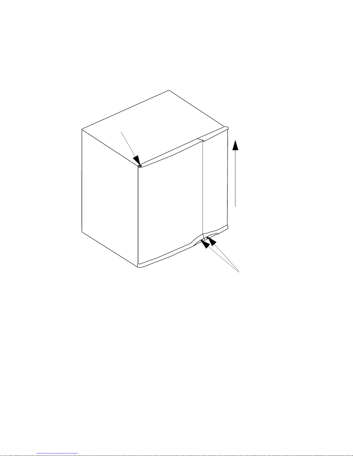
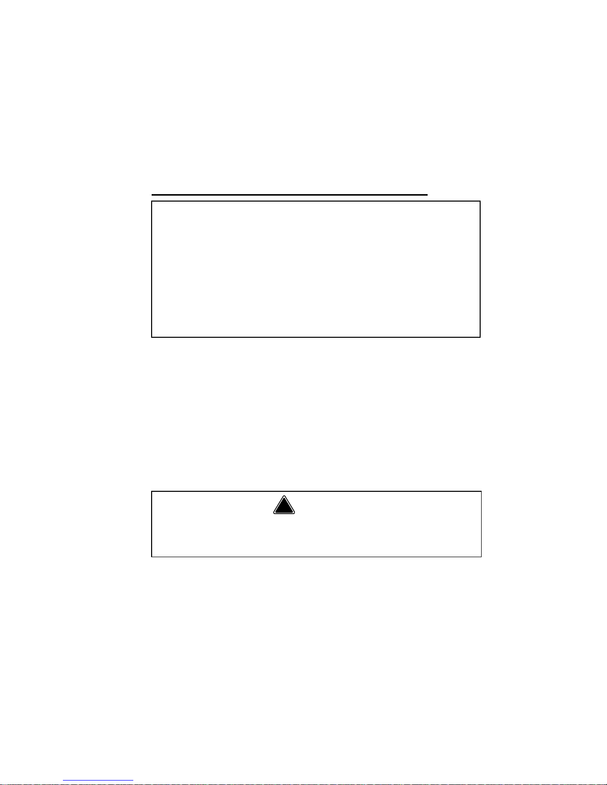
REMOVING THE FRONT PANELS
1. Disconnect power to ice machine.
2. Loosen screws. Do not remove they are retained
by o-rings to prevent loss.
3. To remove right front door lift up and remove.
Door Removal
4. Open left front door to 45 degrees.
5. Support with left hand, depress top pin, tilt top of
door forward and lift out of bottom pin to remove.
3
2
5
Page 27

Part Number 80-1505-3 6/11 27
LOCATION OF CVD® CONDENSING UNIT
The location selected for the CVD Condensing Unit
must meet the following criteria. If any of these criteria
are not met, select another location.
• CVD885/CVD1075/CVD1085/CVD1485/
CVD1885/CVD2085 Only - The air temperature
must be at least -20°F (-28.9°C) but must not
exceed 130°F (54.4°C).
• CVD675/CVD685/CVD1185/CVD2075/CVD3085
Only - The air temperature must be at least
-20°F (-28.9°C) but must not exceed 120°F
(48.9°C).
• CVD1486 Only- The air temperature must be at
least 50°F (10°C) but must not exceed 110°F
(43°C).
• The location must not allow exhaust fan heat and/
or grease to enter the condenser.
• The location must not obstruct airflow through or
around the condensing unit. See below for
clearance requirements.
Page 28

28 Part Number 80-1505-3 6/11
CONDENSING UNIT CLEARANCE
REQUIREMENTS
CVD675/CVD685/CVD885/CVD1075/CVD1085/
CVD1185/
CVD2075/CVD2085
Top/Sides - There is no minimum clearance required,
although 6” (15.2 cm) is recommended for efficient
operation and servicing only.
Front/Back - 48” (122 cm)
CVD1285/CVD1485/CVD1885
Top/Sides - There is no minimum clearance required,
although 6” (15.2 cm) is recommended for efficient
operation and servicing only.
Front - 24” (61 cm)
Back - 48” (122 cm)
CVD1486 ONLY
Top - 5” (12.7 cm) is required for efficient operation
and servicing.
Front/Back/Sides - 12” (30.5 cm)
CVD3085
Top/Sides - There is no minimum clearance required,
although 8” (20.3 cm) is recommended for efficient
operation and servicing only.
Front/Back - 24” (122 cm)
NOTE: 24” (61.0 cm) on all sides is recommended
to allow easy access.
Page 29
Part Number 80-1505-3 6/11 29
BIN INSTALLATION
All ice machines installed on a bin require an ice
deflector. Manitowoc bins have a built in deflector that
requires no modifications when used with a forward
facing evaporator. Ice machines with multiple
evaporators require a deflector kit.
Bin adapters or custom bin tops are available to allow
installation of a 30” ice machine on a 48” or 60” bin.
Refer to ice machine price list for options
(http://www.manitowocice.com/sales/price.asp).
!
Warning
Manitowoc QuietQube ice machines require the
ice storage bin to incorporate an ice deflector.
Prior to using a non-Manitowoc ice storage
system with other Manitowoc ice machines,
contact the manufacturer to assure their ice
deflector is compatible with Manitowoc ice
machines.
Page 30
30 Part Number 80-1505-3 6/11
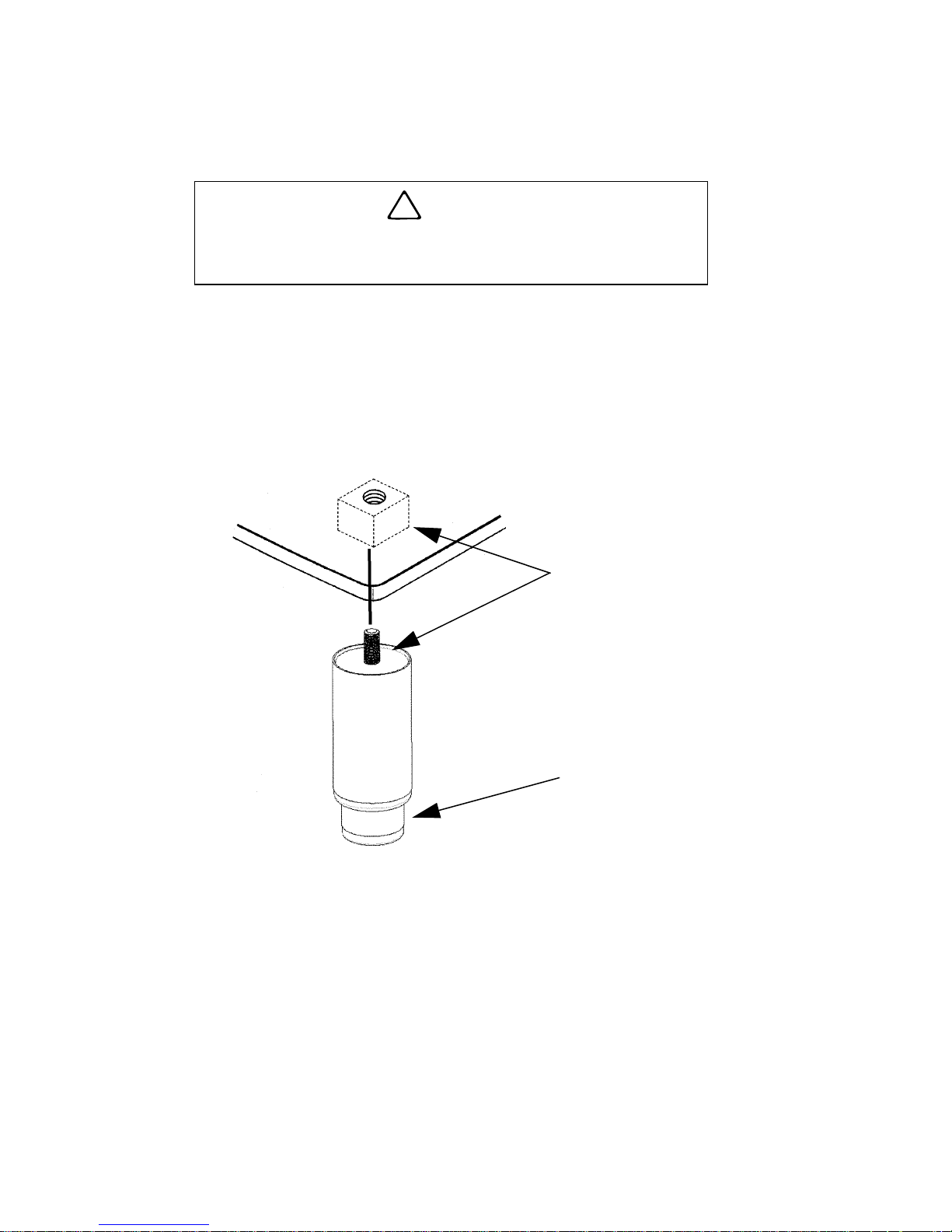
Leveling the Ice Storage Bin
1. Screw the leveling legs onto the bottom of the bin.
2. Screw the foot of each leg in as far as possible.
3. Move the bin into its final position.
4. Level the bin to assure that the bin door closes
and seals properly. Use a level on top of the bin.
Turn each foot as necessary to level the bin.
Leveling Leg and Foot
!
Caution
The legs must be screwed in tightly to prevent
them from bending.
THREAD
LEVELING LEG
INTO BASE AS
FAR AS
POSSIBLE
ADJUST
LEGS TO
LEVEL BIN
Page 31

Part Number 80-1505-3 6/11 31
S1470C/S1870C/S2070C/S2170C
INSTALLATION ON A MANITOWOC BIN
An ice deflector kit is required for installation. Order
appropriate kit (30” or 48”) for your bin.
Step 1 Remove the stock ice deflector.
A. Remove the left and right side cover screws
B. Remove the cover to expose four screws,
which secure the plastic deflector.
C. Remove fours screws and plastic deflector
D. Install polymer spacer on each side and
secure with the four screws.
E. Reinstall cover and screws.
RE-INSTALL TOP
COVER
REMOVE 1
SCREW
ON EACH
SIDE
REMOVE
DEFLECTOR
REMOVE 2
SCREWS
ON EACH
SIDE
Page 32
32 Part Number 80-1505-3 6/11
Step 2 Install front support and filler panels.
A. Remove foam tape from front support
location.
B. Set front support in place and install foam
tape.
C. Position filler panels (align with front support),
drill and secure.
D. Install foam tape on front and back. Seal all
foam tape edges.
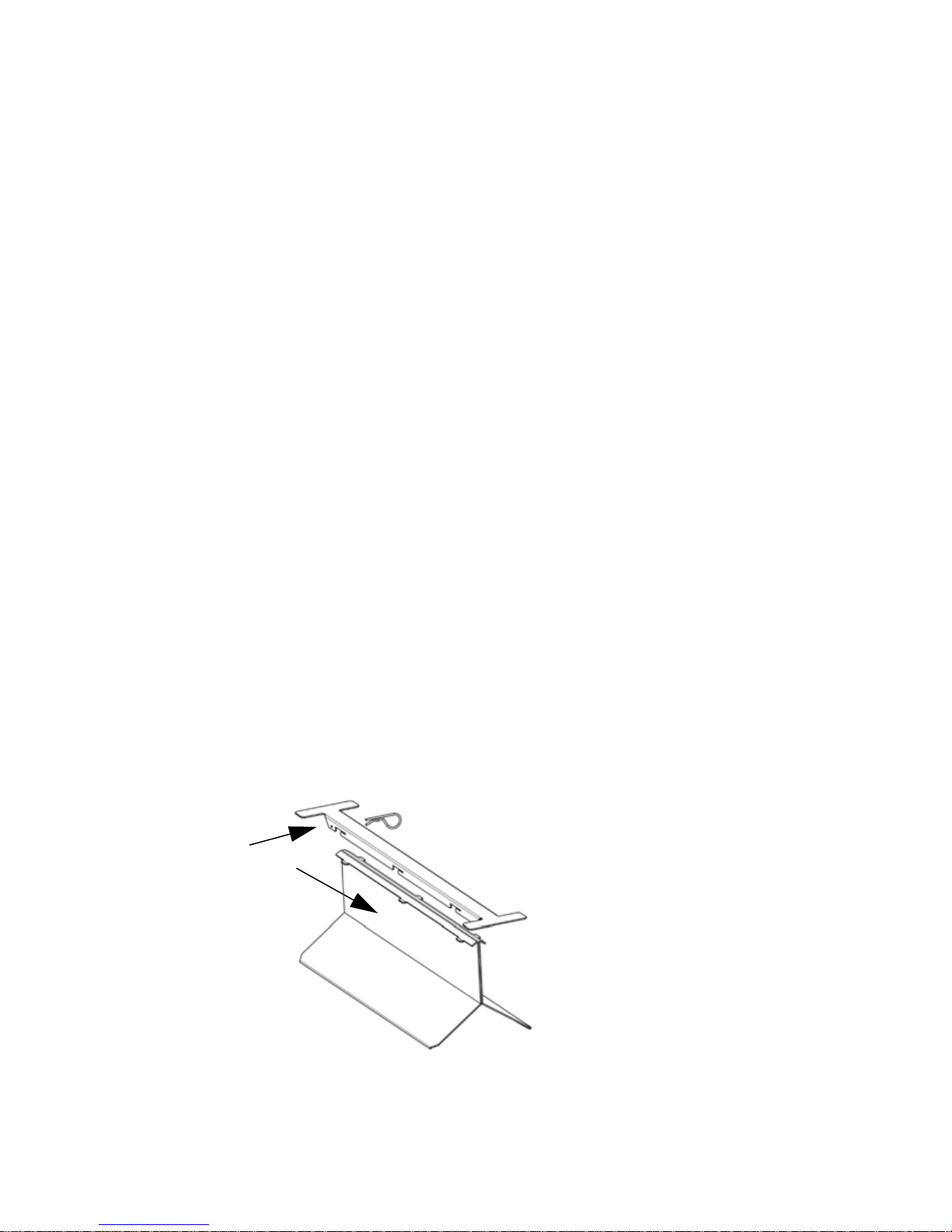
Step 3 Install ice deflector.
A. Locate center of ice machine drop zone
(center is 1 1” from lef t edge of ice machine to
left edge of bracket).
B. Cut and remove foam tape on the front and
the back of the bin where the deflector will be
located.
C. Remove any residual adhesive; areas must
be clean and dry.
D. Remove protective covering from double
sided tape on bottom of deflector bracket.
E. Install deflector bracket; Distribute equally to
the front and back and locate pin to the rear.
F. Apply foam tape over bracket and seal joints
with silicone sealant.
G. Refer to illustration and install deflector in
mounting bracket.
1. SLIDE
FORWARD
2. LOCK IN PLACE WITH PIN
Page 33
Part Number 80-1505-3 6/11 33
ICE MACHINE ON A DISPENSER INSTALLATION
No deflector is needed for machines that match the
size of the dispenser (30” head section on a 30”
dispenser) unless required by the dispenser
manufacturer . Adapters are required when a smaller
ice machine is going on a larger dispenser (22”
machine on a 30” dispenser).
IB0600C/IB0680C/IB0800C/IB1000C
Securing the Ice Machine to the Dispenser
The ice machine and adapter plate must be secured to
the dispenser to prevent tipping.
• T wo holes are located in the front bottom rail of the
ice machine, to allow attachment to the adapter
plate.
• The adapter cover must be secured to the
dispenser to prevent ice from dislodging the cover
during agitation.
Important
Manitowoc Ice/Beverage Ice Machines require
an adapter for mounting. Adapters are not
included with the ice machine, dispenser or bin
and must be ordered separately. When a nonManitowoc adapter is used, verify th e adapter is
compatible with Manitowoc Ice/Beverage Ice
Machines prior to installation.
!
Warning
The ice machine and adapter plate must be
secured to the dispenser to prevent tipping.
Page 34

34 Part Number 80-1505-3 6/11
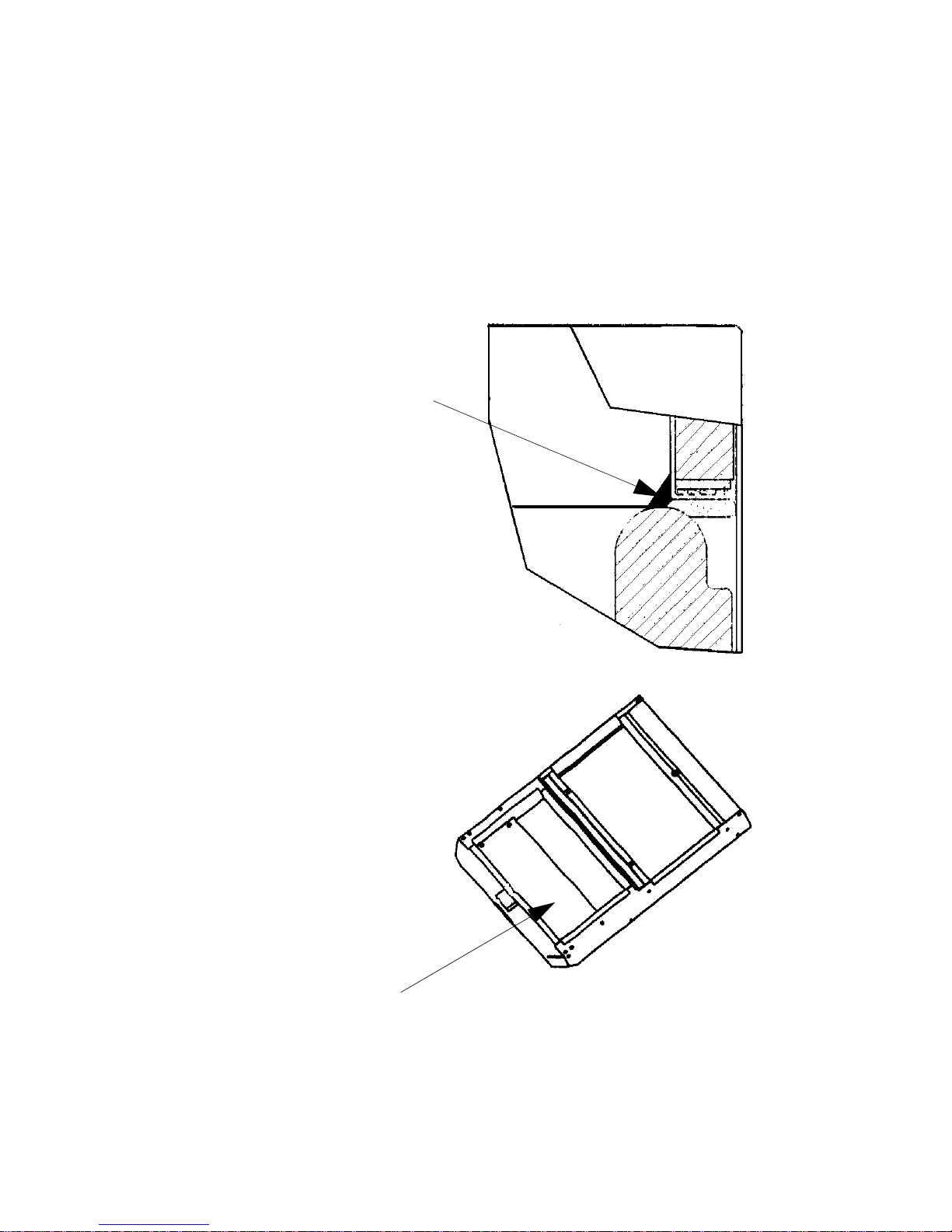
Typical Ice Beverage on a Dispenser
1. Install bin level thermostat bracket.
2. Set adapter on dispenser. Position the adapter so
that the front flange of the adapter will be up
against the front lip of the dispenser. Adapter may
have to be moved towards the back of the
dispenser.
3. Using the slotted holes in the adapter as a
template, drill four (4) 9/64” diameter holes at the
bottom of the slots. Note: Do not drill deeper than
1/4” past the sheet metal. Use a drill stop!
4. Fasten the adaptor to dispenser using the four (4)
#8 screws supplied with the adaptor kit.
5. Set the ice machine on top of the adapter. Align
holes in ice machine front angle with threaded
bosses on the adapter.
BIN
COVER
ADAPTER
SCREWS
Page 35
Part Number 80-1505-3 6/11 35
6. Secure the ice machine to the adaptor with two
(2) #8-32 screws supplied with the kit.
7. Set the bin cover on the adapter, move backwards
until the cover hits the stop, and lower the plastic
cover insuring that the latch locks.
8. To remove the bin cover, twist the knob, lift up,
and pull forward.
PLACE A LARGE FILLET OF
FOOD GRADE RTV INSIDE
EDGE ALONG BOTH SIDES
WHERE ADAPTER
TOUCHES BIN
DEFLECTOR MUST
STAY IN PLACE
Page 36

36 Part Number 80-1505-3 6/11
ICE MACHINE HEAD SECTION WATER
SUPPLY AND DRAINS
Potable Water Supply
Local water conditions may require treatment of the
water to inhibit scale formation, filter sediment, and
remove chlorine odor and taste.
Potable Water Inlet Lines
Follow these guidelines to install water inlet lines:
• Do not connect the ice machine to a hot water
supply . Be sure all hot water restrictors installed for
other equipment are working. (Check valves on
sink faucets, dishwashers, etc.)
• If water pressure exceeds the maximum
recommended pressure obtain a water pressure
regulator from your Manitowoc Distributor.
• Maximum water pressure - 80 psi (551.6 kPA)
• Install a water shut-off valve for ice making potable
water.
• Insulate water inlet lines to prevent condensation.
• A 3’ service loop or disconnect (union) must be
installed at the ice machine head section.
Important
If you are installing a Manitowoc water filter system,
refer to the Installation Instructions supplied with the
filter system for ice making water inlet connections.
Page 37

Part Number 80-1505-3 6/11 37
Drain Connections
Follow these guidelines when installing drain lines to
prevent drain water from flowing back into the ice
machine and storage bin:
• Drain lines must have a 1.5 in. drop per 5 ft. of run
(2.5 cm per meter), and must not create traps.
• The floor drain must be large enough to
accommodate drainage from all drains.
• Run separate bin and ice machine drain lines.
Insulate them to prevent condensation.
• Vent the bin and ice machine drain to the
atmosphere. The ice machine drain requires an
18” vent.
• Drains must have a union or other suitable means
to allow in place disconnection from the ice
machine when servicing is required.
• S3070C requires base drain connection (1” FPT).
Cooling Tower Application (Water-Cooled Models)
A water cooling tower installation does not require
modification of the ice machine. The water regulator
valve for the condenser continues to control the
refrigeration discharge pressure.
It is necessary to know the amount of heat rejection,
and the pressure drop through the condenser and
water valves (inlet and outlet) when using a cooling
tower on an ice machine.
• Water entering the condenser must not exceed
90°F (32.2°C).
• Water flow through the condenser must not
exceed 5 gallons (19 liters) per minute.
• Allow for a pressure drop of 7 psi (48 kPA)
between the condenser water inlet and the outlet
of the ice machine.
• Water exiting the condenser must not exceed
110°F (43.3°C).
Important
The Commonwealth of Massachusetts requires that
all water-cooled models must be connected only to
a closed loop, cooling tower system.
Page 38

38 Part Number 80-1505-3 6/11
WATER COOLED CONDENSER WATER SUPPLY
AND DRAINS
Water Cooled Condenser Lines
Follow these guidelines to install water lines:
• Contact your distributor if your water pressure is
greater than 150 psig (1034 kPA). A special order
condensing unit is available that allows water
pressure up to 350 psig (2413 kPA).
• Install a shutoff valve (inlet and outlet on cooling
tower or closed loop circuits) to allow isolation of
the water system.
• Water entering the condenser must not exceed
90°F (32.2°C).
• Water flow through the condenser must not
exceed 5 gallons (19 liters) per minute.
• Allow for a pressure drop of 8 psig (55 kPA)
between the condenser water inlet and outlet.
• Water exiting the condenser must not exceed
110°F (43.3°C).
• Do not connect to the potable water filter system.
Condensing Unit Drain Connections
The condensing unit drain is provided to remove any
condensate produced by the suction accumulator.
Condensate amounts will vary depending on
temperature and humidity.
• The condensing unit must be level front to back
and side to side to allow the condensate to drain.
• Drain lines must have a 1.5-inch drop per 5 feet of
run (2.5 cm per meter), and must not create traps.
• Drain termination must meet applicable costs.
Page 39

Part Number 80-1505-3 6/11 39
ELECTRICAL REQUIREMENTS
Local or state electrical code, length of wire run or materials
used, can increase the minimum wire or breaker size
requirement. A qualified electrician must determine the wire
and breaker size, although the minimum wire size must meet
or exceed the specifications in these charts.
Head Sections
Ice Machine Head Section
Voltage Phase
Cycle
Max. Fuse/
Circuit
Breaker
Total Amps
S0600C
S0680C
115/1/60
208-230/1/60
230/1/50
15 amp
15 amp
15 amp
1.1
0.6
0.6
S0850C
115/1/60
230/1/50
15 amp
15 amp
1.1
1.5
IB0620C
IB0680C
IB0820C
IB1020C
115/1/60
230/1/50
15 amp
15 amp
1.4
0.8
S1000C
S1200C
115/1/60
230/1/50
15 amp
15 amp
2.5
1.5
S1470C
S1870C
S2070C
S2170C
115/1/60
208-230/1/60
230/1/50*
15 amp
15 amp
15 amp
1.1
0.6
0.6
S3070C
115/1/60
230/50/1
15 amp
10 amp
2.0
2.0
*Not available on S2070C or S2170C models.
**All conductors must be solid copper wire.
Important
The QuietQube® Ice Machine Head Section and
CVD® Condensing Unit are wired independently
from each other.
Page 40

40 Part Number 80-1505-3 6/11
Condensing Units
CVD® Condensing Unit
Voltage
Phase
Cycle
Max. Fuse/
Circuit
Breaker
Min.
Circuit
Amps
CVD0675
208-230/1/60
208-230/3/60
230/1/50
15 amp
15 amp
15 amp
9.6
7.3
9.0
CVD0685
208-230/1/60
208-230/3/60
15 amp
15 amp
11.0
7.5
CVD0885
208-230/1/60
208-230/3/60
230/1/50
20 amp
15 amp
20 amp
11.8
9.1
10.0
CVD1075
208-230/1/60
208-230/3/60
230/1/50
25 amp
20 amp
25 amp
15.6
10.6
13.8
CVD1085
208-230/1/60
208-230/3/60
230/1/50
20 amp
15 amp
20 amp
12.5
9.4
10.9
CVD1185
208-230/1/60
208-230/3/60
230/1/50
25 amp
15 amp
20 amp
15.7
10.8
11.2
CVD1285
208-230/1/60
208-230/3/60
230/1/50
25 amp
20 amp
20 amp
14.7
10.6
11.7
CVD1485
208-230/1/60
208-230/3/60
230/1/50
20 amp
15 amp
30 amp
20.0
15.0
20.0
CVD1486
208-230/1/60
208-230/3/60
230/1/50
20 amp
15 amp
20 amp
20.0
15.0
20.0
CVD1885
208-230/1/60
208-230/3/60
230/1/50
40 amp
25 amp
30 amp
25.0
20.0
20.0
CVD2085*
208-230/1/60
208-230/3/60
50 amp
40 amp
40.0
30.0
CVD3085*
208-230/3/60
460/3/50
35 amp
15 amp
30.0
15.0
*CVD2085 & CVD3085 Only - Verify the direction of the rotation is
correct on the 3ph scroll compressor. The ice machine will have
high suction pressure, low discharge pressure and will be
noticeably loud. Reverse two incoming power leads to reverse
rotation.
Page 41

Part Number 80-1505-3 6/11 41
REFRIGERATION SYSTEM INSTALLATION
**NOTE: The CVD2075 has a suction line fitting of 7/8” and a
liquid line fitting of 5/8”. Since the line set is sized differently,
please use the provided bushings to properly connect the line
set to the CVD condensing unit.
QuietQube®
Ice Machine
Remote Single
Circuit
Condenser
Line Set*
S0600C
IB0620C
CVD675
RC-21
RC-31
RC-51
S0680C
IB0680C
CVD685
S0850C
IB0820C
CVD885
S1000C
IB1020C
CVD1085
S1200C CVD1285
RC-20
RC-30
RC-50
IB1020C
CVD1185
CVD1285
CVD1075
S1470C
CVD1485
CVD1486
S1870C CVD1885
S2070C CVD2075
S2170C CVD2085
RC-23
RC-33
RC-53
S3070C CVD3085
RC-24
RC-34
RC-54
*Line Set
Suction
Line
Liquid
Line
Insulation
Thickness
RC 21/31/51
5/8 in.
(15.9 mm)
3/8 in.
(9.5 mm)
Suction Line
1/2" (13mm)
Liquid Line
1/4" (7mm)
RC 20/30/50**
3/4 in.
(19.1 mm)
1/2 in.
(12.7 mm)
RC 23/33/53
3/4 in.
(19.1 mm)
5/8 in.
(15.9 mm)
RC 24/34/54
T wo Lines -
3/4 in.
(19.1 mm)
One Line -
5/8 in.
(15.9 mm)
Page 42

42 Part Number 80-1505-3 6/11
Usage With Non-Manitowoc Condensing Units
Manitowoc CVD® Condensing Units are specifically
designed for usage with a QuietQube® Ice Machine
Head Section. Standard condensing units and NonManitowoc condensing units will not operate a
QuietQube® Ice Machine Head Section.
Factory Equipment Refrigera nt Amounts
ICE MACHINE HEAD SECTION
Each ice machine head section ships from the factory
with a R-404A refrigerant charge appropriate for the
entire system operation. The serial tag on the ice
machine indicates the refrigerant charge. The
refrigerant charge is sufficient to operate the ice
machine in ambient temperatures between -20°F to
130°F (-28.9°C to 54.4°C)*. With line set lengths of up
to 100 feet (30.5 m).
*CVD685/CVD1 185/CVD2085/CVD3085 =
-20°F to 120°F (-29°C to 49°C)
CVD1486 = 50°F to 11 0°F (10°C to 43°C)
Important
Manitowoc remote systems are only approved and
warranted as a complete new package. Warranty on
the refrigeration system will be void if a new ice
machine head section is connected to pre-existing
(used) tubing or condensing units or vice versa.
!
Caution
Never add more than nameplate charge to the
refrigeration system for any application.
!
Caution
The 60-month compressor warranty (including the
36-month labor replacement warranty) will not apply
if the Manitowoc Ice Machine and Manitowoc C VD
®
Condensing Unit are not installed according to
specifications. This warranty also will not apply if the
refrigeration system is modified with a condenser,
heat reclaim device, or other parts or assemblies not
manufactured by Manitowoc Ice.
Page 43

Part Number 80-1505-3 6/11 43
CVD® CONDENSING UNIT
Each condensing unit ships from the factory
pressurized with 50/50 nitrogen helium mixture that
must be removed during the installation process
(approximately 20 psig).
REFRIGERATION LINE SETS/TR AP KIT
Refrigeration Rated Tubing and Trap Kits are shipped
capped with atmospheric pressure.
!
Warning
Potential Personal Injury Situation
The ice machine head section contains the
refrigerant charge. Installation and brazing of the line
sets must be performed by a properly trained and
EPA certified refrigeration technician aware of the
dangers of dealing with refrigerant charged
equipment.
!
Warning
Installation of a QuietQube® Condensing Unit may
require the use of special equipment for placement.
Trained and qualified personnel are required for
proper rigging and lifting.
Page 44

44 Part Number 80-1505-3 6/11
Refrigeration Line Set Installation
Refrigeration line set installation consists of vertical
and horizontal line set distances between the ice
machine and the condensing unit. The following
guidelines, drawings and calculation methods must be
followed to assure proper oil return and CVD
®
Condensing Unit/ice Machine operation.
The refrigeration line set installer must be USA
Government-Environmental Protection Agency (EPA)
certified in proper refrigerant handli ng and servicing
procedures.
VERIFY ICE MACHINE AND CVD® CONDENSING
UNIT LOCATIONS ARE WITHIN GUIDELINES.
Prior to installation of the ice machine and CVD®
Condensing Unit be sure that the distance between
them is within the line set routing guidelines outlined in
this manual.
Roof/Wall Penetration
If required, cut a 3-inch (76.2 mm) circular hole in the
wall or roof for routing of refrigeration tubing. A
qualified person must perform all roof penetrations.
ROUTE REFRIGERATION TUBING
Properly route refrigeration tubing between the ice
machine head section and the CVD® condensing unit.
!
Warning
The ice machine head section contains refrigerant
charge. The ice machine head section contains
three (3) refrigeration valves that must remain
closed until proper installation of the line sets is
completed.
!
Warning
Disconnect electrical power to the ice machine head
section and CVD® condensing unit before
proceeding.
Page 45

Part Number 80-1505-3 6/11 45
A. LINE SET LENGTH
100 feet (30.5 m) Length: The maximum measured
length the line set can be.
The receiver is designed to hold a charge sufficient to
operate the ice machine in ambient temperatures
between -20°F (-28.9°C) and 130°F (54.4°C)*, with
line set lengths of up to 100 feet (30.5 m).
*CVD685/CVD1 185/CVD2085/CVD3085 =
-20°F to 120°F (-29°C to 49°C)
CVD1486 = 50°F to 11 0°F (10°C to 43°C)The
maximum amount of lineset which can be exposed on
the rooftop is 25% of the total length of the lineset.
!
Caution
QuietQube® Ice Machines will not function with li ne
sets greater than 100 ft. (30.5 m). Do not attempt to
go beyond this distance and add refrigerant charge
to compensate!
Important
QuietQube® ice machines will not function with line
sets greater than 100 feet (30.5 m). Do not attempt
to go beyond this distance and add refrigerant
charge to compensate!
Page 46

46 Part Number 80-1505-3 6/11
B. Line Set Rise or Drop
35 ft. (10.7 m) Rise: The maximum distance the CVD
®
Condensing Unit can be above the ice machine.
15 ft. (4.5 m) Drop: The maximum distance the CVD
®
Condensing Unit can be below the ice machine.
SV1751
35 FT. (10.7 M)
MAXIMUM
DISTANCE
SV1750
15 FT. (4.5 M)
MAXIMUM
DISTANCE
Page 47

Part Number 80-1505-3 6/11 47
C. Suction Line Oil Traps
0 to 20 ft. (0 to 6.1 m) Rise: The ice machine head
section has one oil trap built in which allows for a
maximum condenser rise of 20 ft. (6.1 m) without
additional traps in the suction line.
21 to 35 ft. (6.4 to 10.7 m) Rise: The suction line
requires an additional oil trap (“S” type) to be installed.
Install the trap as close as possible to midpoint
between the ice machine head section and CVD
®
Condensing Unit. S-Trap Kits are available from
Manitowoc (refer to chart).
MANITOWOC S-TRAP KIT
!
Caution
Do not form unwanted traps in refrigeration lines.
Never coil excess refrigeration tubing.
Model
S-Trap
Kit
Number
Tubing Size
S600C IB600C
S680C IB680C
S850C IB800C
S1000C
K00172
5/8 inch
(15.9 mm)
IB1000C S1200C
S1470C S1870C
S2070C S2170C
S3070C*
K00166
3/4 inch
(19.1 mm)
* Requires two S-T r ap kits, one for each suction line.
21 FT. OR
MORE RISE
ADDITIONAL
TRAP KIT
REQUIRED.
Page 48

48 Part Number 80-1505-3 6/11
SERVICE LOOP
• The supplied service loop (on Ice Beverage ice
machines) is an installation requirement.
Excess tubing length must be sufficient to
allow 180° rotation of the ice machine.
• A service loop is not considered an oil trap.
• The service loop is not included when calculating
length, rise or drop of the tubing run.
• Do not use hard rigid copper for the service loop.
Step 4 Lengthening or Reducing Line Set Lengths
When the line set requires shortening or lengthening,
do so before connecting the line set to the ice machine
head section or the CVD
®
Condensing Unit.
Step 5 Connecting the line set.
To prevent oxidation of the copper, purge line set and
condensing unit with dry nitrogen while brazing.
!
Caution
If a line set has a rise followed by a drop, another
rise cannot be made. Likewise, if a line set has a
drop followed by a rise, another drop cannot be
made.
!
Caution
Do not form unwanted traps in refrigeration lines.
Never coil excess refrigeration tubing.
!
Warning
The ice machine head section contains refrigerant
charge. The ice machine head section contains
three (3) refrigeration valves that must remain
closed until proper installation of the line sets is
completed.
Page 49
Part Number 80-1505-3 6/11 49
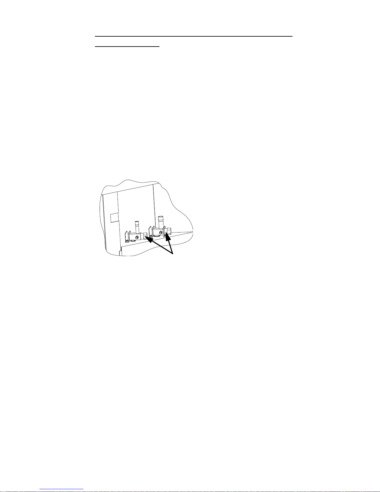
CONNECT THE LINE SET TO THE ICE MACHINE
HEAD SECTION
The line set can be routed for entry through the top or
rear of the ice machine head section.
• Top routing requires the cover to be trimmed.
• Rear routing requires the use of the supplied 90°
elbows.
The line set shut-off valves at the back of the ice
machine must remain closed and be protected from
heat during the brazing process. Wrap the valves in a
wet rag or other type of heat sink prior to brazing. Cool
braze joint with water immediately after brazing to
prevent heat migration to the valve.
VALVES MUST REMAIN CLOSED AND BE
PROTECTED FROM HEAT WHEN BRAZING
(WRAP WITH WET RAG)
Page 50
50 Part Number 80-1505-3 6/11
CONNECT THE LINE SET TO THE CVD®
CONDENSING UNIT
The compressor oil rapidly absorbs moisture. Be
prepared to complete line set installation and start
your evacuation process in order to minimize the time
the compressor is exposed to the atmosphere.
(Maximum amount of time the system can be exposed
to the atmosphere is 15 minutes.)
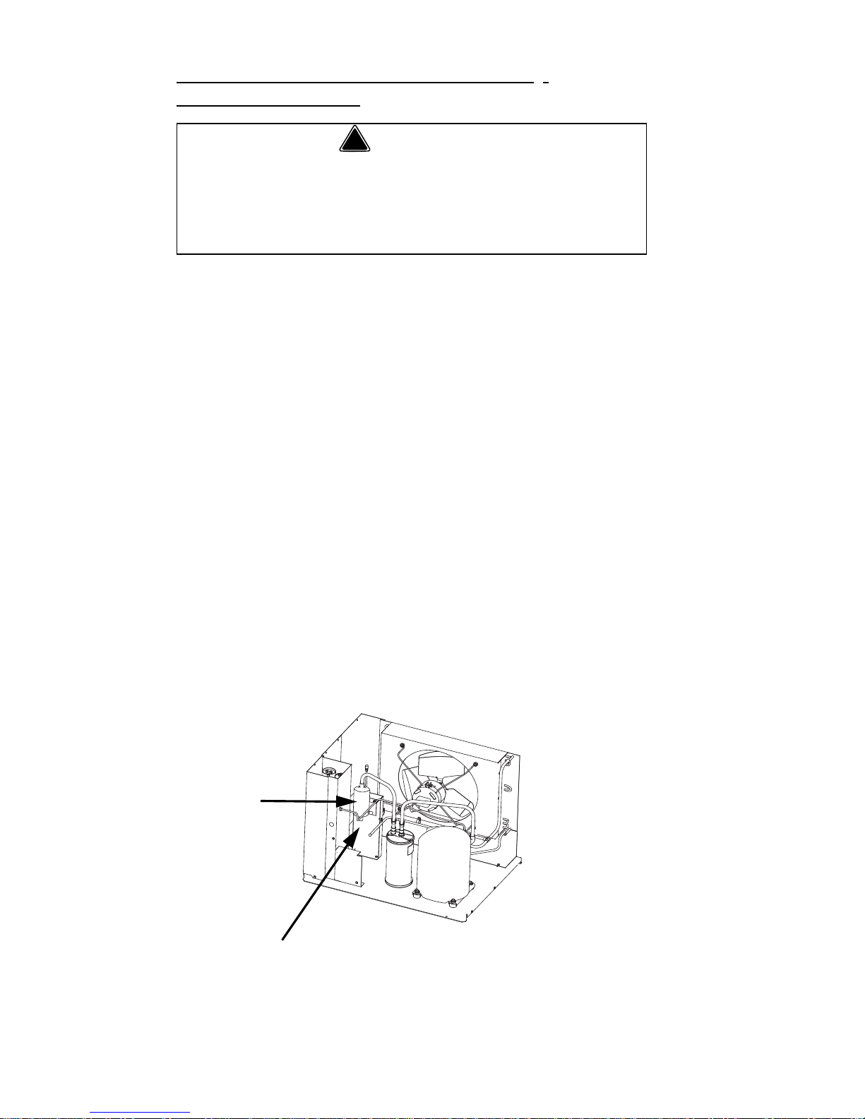
The line set can be routed for entry through the front or
left side of the condensing unit.
• Remove knockout for side location.
• Insert supplied plastic bushings in knockout holes
to prevent tubing from contacting sheet metal.
• Use the supplied 90° elbows to route tubing.
• Cut the tubing ends of the suction and liquid lines
and braze line sets to the condensing unit.
• S3070C Only - use the provided tee to connect
the 2 suction lines from the head section to the
suction line on the condensing unit.
!
Warning
The condensing unit ships from the factory
pressurized with a 50/50 mixture of nitrogen/helium.
Bleed off pressure from both suction and liquid li ne
access ports prior to cutting into refrigeration lines.
MINIMIZE THE TIME THE REFRIGERATION
SYSTEM IS EXPOSED T O THE ATMOSPHERE
(15 MINUTES MAXIMUM).
SUCTION
FILTER
SUCTION LINE
Page 51
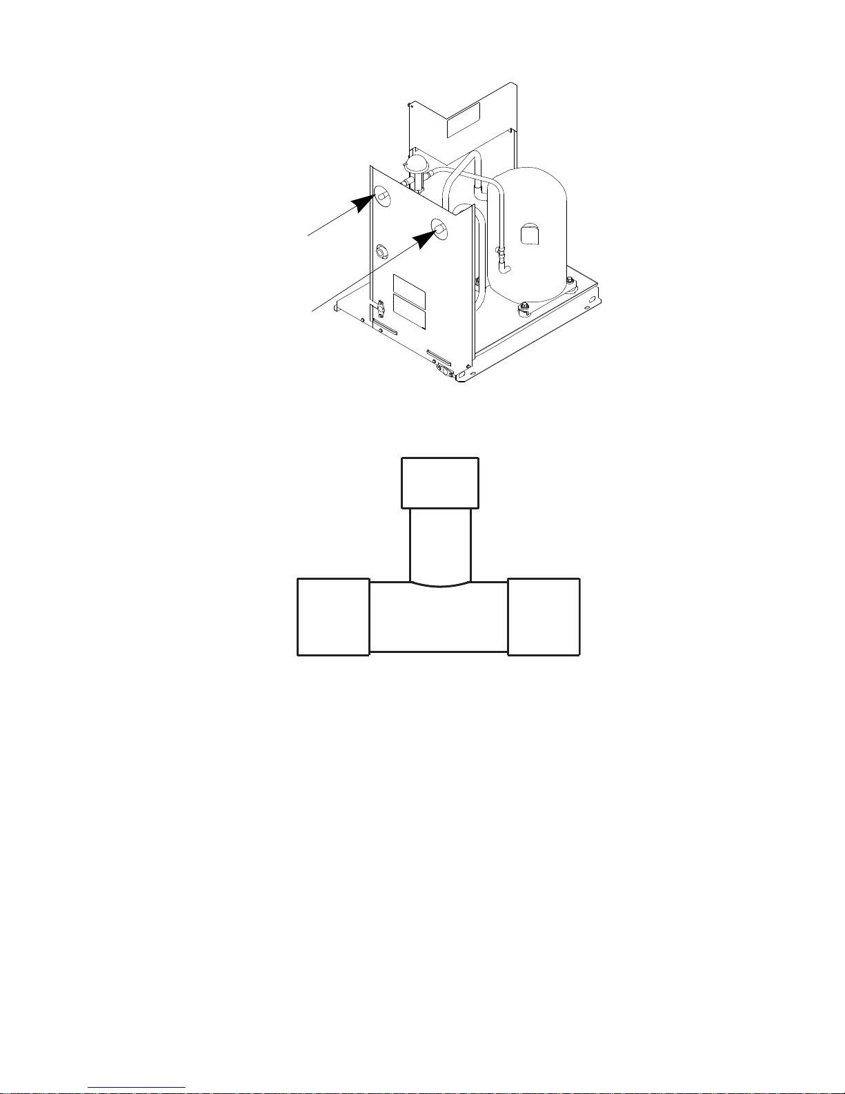
Part Number 80-1505-3 6/11 51
LIQUID
LINE
SUCTION
LINE
SUCTION
LINE
FROM
HEAD
SECTION
SUCTION
LINE
FROM
HEAD
SECTION
SUCTION LINE ON
CONDENSING UNIT
S3070C TUBING
MUST BE
CONNECTED TO
TEE AS SHOWN
Page 52

52 Part Number 80-1505-3 6/11
PRESSURE TEST AND EVACUATE THE LINE SET
AND CVD CONDENSING UNIT
Schrader valve core removal tools that allow for
removal and installation of the valve cores without
removing manifold gauge set hoses are recommended
to decrease the evacuation time.
Leave the line set shut-off valves closed (front seated).
All CVD condensing units manufactured after
December 2009 contain a check valve in the
compressor discharge line. The check valve
requires an additional connection on the co ndensing
unit during evacuation and recovery procedu res.
Connections are required at five points:
Ice Machine Head Section
1. Receiver Service Valve
2. Low Side Access Valve
3. High Side Access Valve
CVD Condensing Unit
4. Compressor Discharge Access Valve
5. Suction Filter Access Valve
Page 53
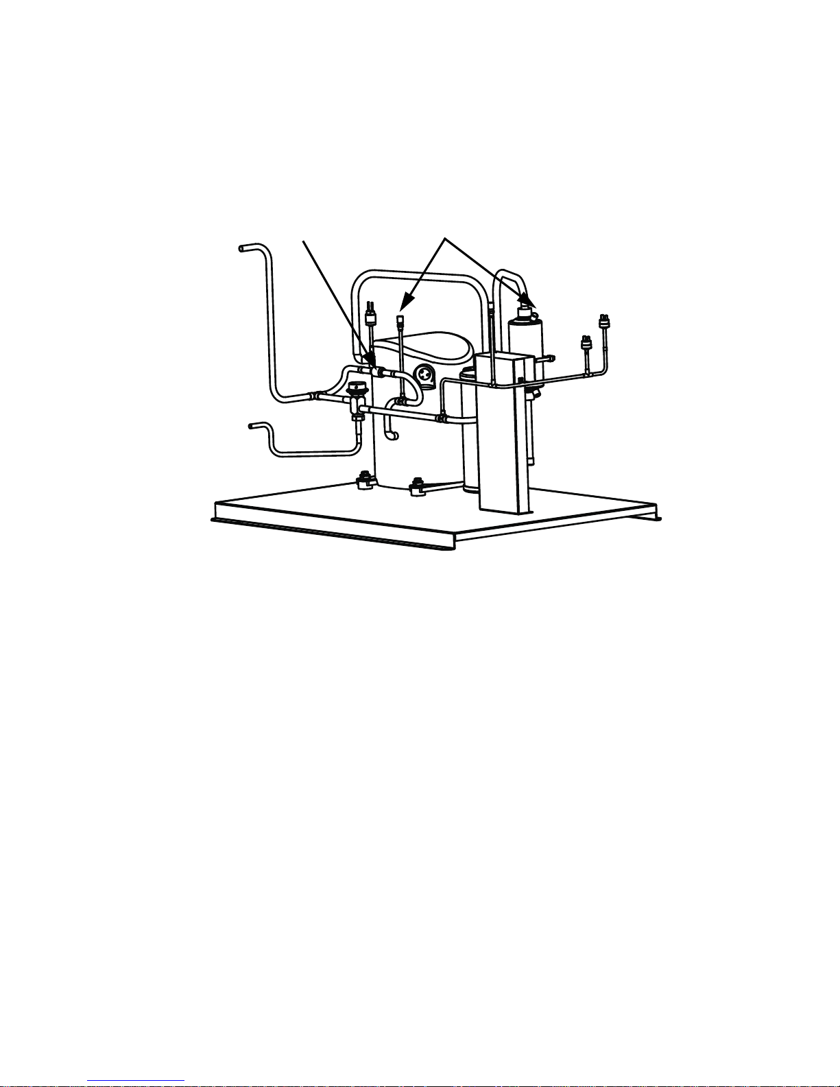
Part Number 80-1505-3 6/11 53
Connection of a manifold gauge set (or a hose with
core depressors on both ends) between the suction
filter access port and the compressor access valve
(located between the compressor and discharge line
check valve) is required.
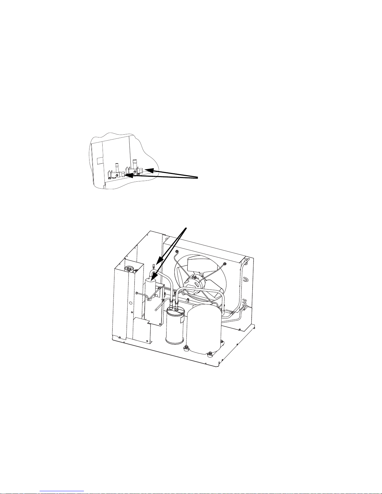
Pressure test the line sets and CVD
®
Condensing Unit
with 150 psig of dry nitrogen. Add nitrogen at the line
set shut-off valves located at the back of the ice
machine head section or from the schrader valves
located in the CVD® Condensing Unit. Complete the
pressure test, verify no leaks are present and remove
the nitrogen from the system before connecting the
vacuum pump.
CHECK VALVE
CONNECT MANIFOLD GAUGE SET OR
HOSE WITH CORE DEPRESSORS ON BOTH ENDS
C
O
N
D
E
N
S
E
R
LINESET
CONNECTION
LOCATION
Page 54
54 Part Number 80-1505-3 6/11
Connect a vacuum pump to both of the line set shut-off
valves located at the back of the ice machine head
section or from the schrader valves located in the
CVD
®
Condensing Unit. Schrader valve core removal
tools (that allow for putting the cores back in without
removing vacuum pump hoses) will greatly decrease
evacuation time.
Evacuate to 500 microns (or less) at the CVD
condensing unit.
Isolate the vacuum pump from the line set shut-off
valves and/or condensing unit access ports prior to
proceeding.
CONNECT VACUUM
PUMP TO LINE SET
SHUT-OFF VALVES.
ALTERNATE CONNECTIONS AT
CONDENSING UNIT SCHRADER VALVES
Page 55

Part Number 80-1505-3 6/11 55
OPEN REFRIGERATION SERVICE VALVES
The suction line, liquid line and receiver service valves
are closed during shipment and installation.
Open the valves prior to starting the ice machine.
A. Slowly backseat (open – turn
counterclockwise) the suction line shut-off
valve.
B. Slowly backseat (open – turn
counterclockwise) the liquid line shut-off
valve.
C. Slowly backseat (open-turn
counterclockwise) the receiver service valve.
NOTE: You will not hear refrigerant flow when the valves are
opened. Refrigerant will not flow until the toggle switch is
placed in the ice position and the solenoid valve opens.
USE ALLEN WRENCH TO OPEN
(TURN COUNTERCLOCKWISE)
LIQUID AND SUCTION LINE
SHUT-OFF VALVES.
USE ALLEN WRENCH TO
OPEN (TURN
COUNTERCLOCKWISE)
LIQUID AND SUCTION LINE
SHUT OFF V ALVES
IB Series
S600C/S680C/S850C/S1000C/S1200C
OPEN SUCTION AND LIQUID LINE SHUT OFF VALVES
Page 56
56 Part Number 80-1505-3 6/11
USE ALLEN WRENCH TO
OPEN (TURN
COUNTERCLOCKWISE)
LIQUID AND SUCTION LINE
SHUT OFF VALVES
OPEN SUCTION AND LIQUID LINE SHUT OFF VALVES
S1470C/S1870C/S2070C/S2170C
Page 57
Part Number 80-1505-3 6/11 57
S3070C
!
Caution
After opening suction, discharge and receiver
service valves, refrigerant pressure will not be
detected until the toggle switch is placed in the ice
position and the harvest valve energizes.
Important
All refrigeration valve caps must be reinstalled to
prevent future refrigeration leaks.
USE ALLEN WRENCH
TO OPEN (TURN
LIQUID AND SUCTION
LINE SHUT OFF
VALVES
Page 58

58 Part Number 80-1505-3 6/11
Verify O-rings in schrader valve caps are intact and
reinstall on shut-off valves to prevent refrigerant
leakage. Replace shut-off valve access caps and
torque to the following specifications.
Replace cap on receiver service valve and tighten.
There is a liquid line solenoid valve at the outlet of the
receiver; refrigerant will not flow to the condensing unit
until the ice machine head section is started. Connect
power to both the ice machine head section and the
CVD
®
Condensing Unit. Place the ice machine toggle
switch into the ICE position; this will allow refrigerant
to enter the line set and condensing unit.
LEAK CHECK THE REFRIGERATION SYSTEM
Leak check the new line set connections at the ice
machine head section, condensing unit and S-trap as
well as all factory joints throughout the entire system.
Disconnect power to the CVD
®
Condensing Unit.
Place the ICE/OFF/CLEAN toggle switch in the ICE
position. This allows the low side and high side
pressures to equalize. Place the ICE/OFF/CLEAN
toggle switch in the OFF position. Connect power to
the CVD
®
Condensing Unit and allow system to pump
down.
Torque Values
Stem 18-20 ft. lbs.
Caps 12-15 ft. lbs.
Schrader Core 1.5-3 in. lbs.
SV1756
TURN
COUNTERCLOCKWISE
TO OPEN.
RECEIVER SERVICE VALVE CAP
(TURN COUNTERCLOCKWISE
TO REMOVE.)
RECEIVER SERVICE VALVE
Page 59

Part Number 80-1505-3 6/11 59
INSULATION REQUIREMENTS
To prevent condensation, the entire suction line
including the shut-off valve must be insulated. All
insulation must be airtight and sealed at both ends.
The following insulation requirements prevent
condensation at 90°F (32.2°C) ambient 90% Relative
Humidity. If higher humidity is expected, increase
insulation thickness.
The entire suction line set, including the suction service
valve located on the back of the ice machine, requires:
Suction Line Liquid Line
Min. Insulation
Thickness
3/4 inch
(19.1 mm)
1/2 inch
(12.7 mm)
1/2”(13mm)
Suction Line
1/4” (7mm)
Liquid Line
5/8 inch
(15.9 mm)
3/8 inch
(9.5 mm)
3/4 inch
(19.1 mm)
5/8 inch
(15.9 mm)
Important
To prevent condensation the entire suction line
including the shut off valve must be insulated. All
insulation must be airtight and sealed at both ends.
The minimum requirements are for conditions at or
below 90% humidity and 90°F (32.2°C) ambient.
When higher humidity will be experienced, insulation
wall thickness will need to be increased.
Page 60

60 Part Number 80-1505-3 6/11
Suction Shut-off Valve Insulation
The preformed suction shut-off valve insulation is
located in the plastic bag taped to the water curtain.
A. Verify valve and schrader caps are tightened
to specifications (see step 6).
B. Place insulation over schrader valve cap and
left side of valve. Position the tab between
the mounting bracket and rear panel.
C. Fold insulation and hold against right hand
side of valve while securing with electrical
tape. Seal the line set insulation to the shutoff valve insulation with electrical tape.
PREFORMED
INSULATION
TIGHTEN VALVE CAPS
TO SPECIFICATIONS.
PLACE TAB BETWEEN
VALVE BODY AND PANEL.
FOLD INSULA TION OVER
RIGHT SIDE OF VALVE
AND SECURE WITH
ELECTRICAL TAPE.
Page 61

Part Number 80-1505-3 6/11 61
Operational Checks
GENERAL
Your Manitowoc ice machine was factory-operated
and adjusted before shipment. Normally, a newly
installed ice machine does not require any adjustment.
To ensure proper operation, always perform these
Operational Checks when starting the ice machine:
• For the First Time
• After a Prolonged Out-of-Service Period
• After Cleaning and Sanitizing
Routine adjustments and maintenance procedures
outlined in this manual are not covered by the
warranty.
WATER LEVEL
The water level sensor is set to maintain the proper
water level above the water pump housing. The water
level is not adjustable.
If the water level is incorrect, check the water level
probe for damage (probe bent, etc.). Clean, repair or
replace the probe as necessary.
Page 62

62 Part Number 80-1505-3 6/11
ICE THICKNESS CHECK
After a harvest cycle, inspect the ice cubes in the ice
storage bin. The ice thickness probe is factory-set to
maintain the ice bridge thickness at 1/8” (3.2 mm).
NOTE: Make sure the water curtain is in place when
performing this check. It prevents water from splashing
out of the water trough.
1. Inspect the bridge connecting the cubes. It should
be about 1/8" (3.2 mm) thick.
2. If adjustment is necessary, turn the ice thickness
probe adjustment screw clockwise to increase
bridge thickness, counterclockwise to decrease
bridge thickness. Set at 1/4” gap between ice
machine and evaporator as starting point, then
adjust to achieve a 1/8" bridge thickness.
NOTE: Turning the adjustment 1/3 of a turn will
change the ice thickness about 1/16" (1.5 mm).
3. Make sure the ice thickness probe wire and
bracket do not restrict movement of the probe.
SV3113
ADJUSTING
SCREW
ICE THICKNESS ADJUSTMENT
1/8” ICE BRIDGE THICKNESS
Page 63

Part Number 80-1505-3 6/11 63
HARVEST SEQUENCE WATER PURGE
The Harvest sequence water purge adjustment may
only be used when the ice machine is hooked up to
special water systems, such as a reverse osmosis or
de-ionized water treatment system.
• The Harvest sequence water purge may be set to
0 or 45 seconds. Repositioning the jumper will set
the harvest water purge to 0 seconds. This setting
does not affect the SeCs or AuCS (cleaning)
sequences.
• During the Harvest sequence water purge, the
water fill valve energizes and de-energizes by
time. The water purge must be at the factory
setting of 45 seconds for the water fill valve to
energize during the last 15 seconds of the water
purge. If it is set to 0 seconds, the water fill valve
will not energize during the water purge.
!
Warning
Disconnect electric power to the ice machine at the
electrical disconnect before proceeding.
Important
The Harvest sequence water purge is factory-set at 45
seconds. A shorter purge setting (with standard water
supplies such as city water) is not recommended. This can
increase water system cleaning and sanitizing
requirements.
45 second
setting
0 second
setting
Page 64

64 Part Number 80-1505-3 6/11
Electronic Bin Thermostat Instructions
IB600C/IB680C/IB800C/IB1000C Only
POSITIONING
1. Remove water trough.
2. Refer illustration below.
A. Loosen rear screw.
B. Remove front screw & rotate probe/bracket.
C. Re-install front screw & tighten.
D. Tighten rear screw.
3. Re-install water trough.
4. Remove slack from sensor probe wire and verify wire
does not contact or obstruct the water curtain or water
level probe.
5. The control is preset and does not require programming.
For control specifications refer to page page 193.
Bin Thermostat Location
Control Location
Final Position
A. Loosen
Rear
Screw
B. Remove
Front Screw &
Rotate Probe/
Bracket.
Re-install
Screw
Control
Location
Page 65

Part Number 80-1505-3 6/11 65
This Page Intentionally Left Blank
Page 66

66 Part Number 80-1505-3 6/11
This Page Intentionally Left Blank
Page 67
Part Number 80-1505-3 6/11 67
Component Identification
ICE MACHINE HEAD SECTIONS
S600C/S680C/S850C/S1000C/S1200C
WATER CURTAIN
CONTROL BOX
WATER
DISTRIBUTION
TUBE
TOGGLE
SWITCH
WATER
TROUGH
REFRIGERATION
ACCESS VALVES
ICE
THICKNESS
CONTROL
EVAPORATOR
WA TER LEVE L
PROBE
WATER PUMP
WATER INLET
LOCATION, THE
WA TER INLET V AL VE
IS LOCATED IN THE
REFRIGERATION
COMP ARTMENT
Page 68
68 Part Number 80-1505-3 6/11
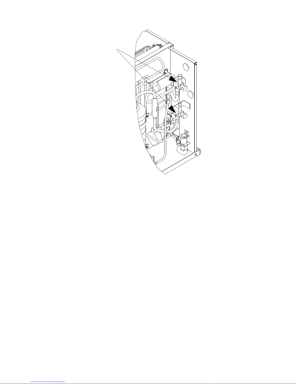
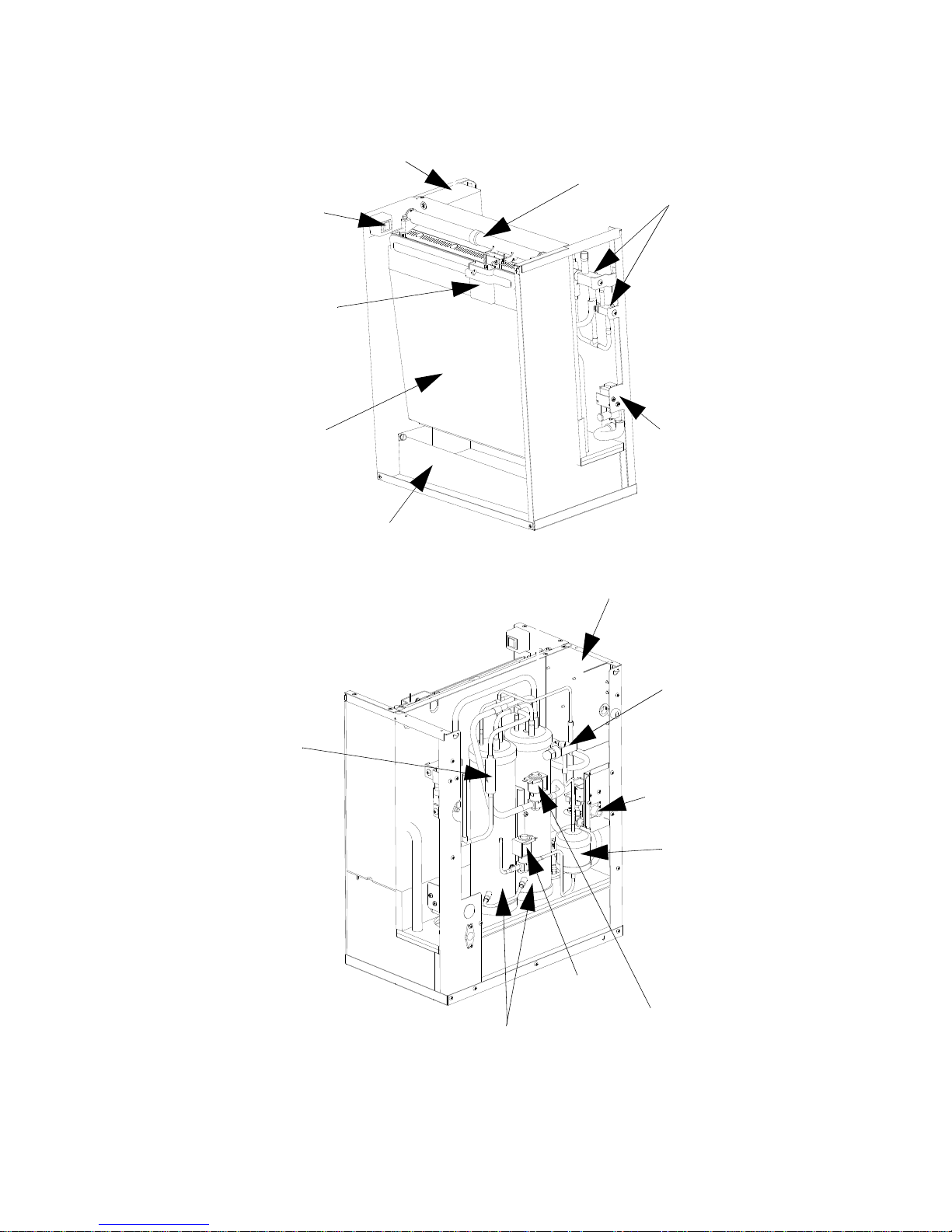
S1470C/S1870C/S2070C/S2170C
AIR
PUMP
DISTRIBUTION
TUBE
ICE
THICKNESS
PROBE
EVAPORATOR
SPLASH
SHIELD
BIN
SWITCH
WATER
TROUGH
SHIELD
ICE
DAMPER
WATER
TROUGH
WATER
PUMP
DUMP
VALVE
RECEIVER
LIQUID LINE
SOLENOID
VALVE
DRIER
ICE/OFF/
CLEAN
SWITCH
WATER
LEVEL
PROBE
LEFT SIDE
HARVEST
VALVE
TXV SENSING
BULB
BOOT
AIR
PUMP
EXPANSION
VALVE
WATER
INLET
VALVE
Page 69
Part Number 80-1505-3 6/11 69
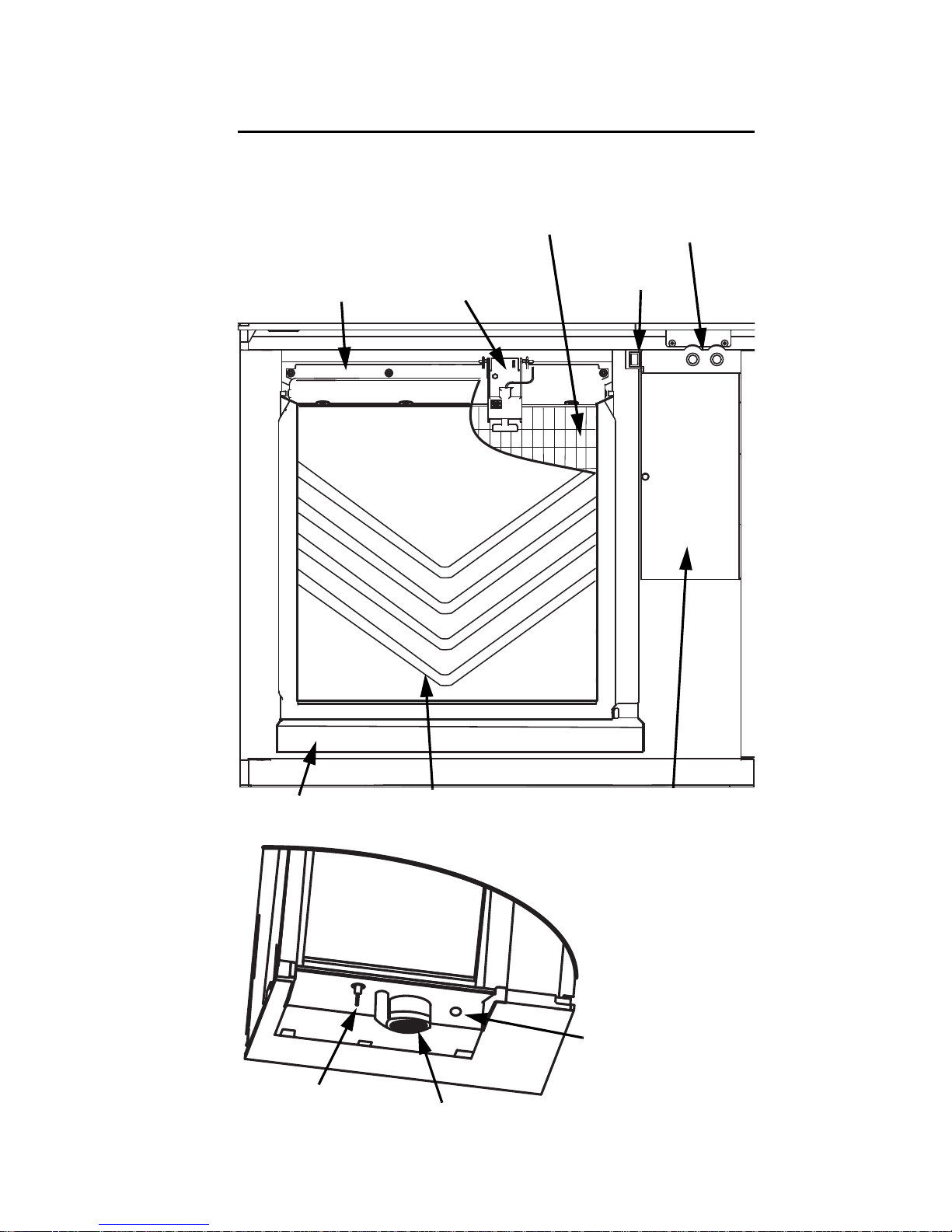
IB0600C/IB0680C/IB0800C/IB1000C
WATER
DISTRIBUTION
TUBE
WATER
CURTAIN
DUMP
VALVE
SHUT OFF
VALVES
ELECTRICAL
COMPARTMENT
ICE/OFF/CLEAN
TOGGLE
SWITCH
ICE
THICKNESS
PROBE
WATER
TROUGH
COOL
VAPOR
VALVE
LIQUID LINE
SOLENOID
VALVE
RECEIVERS
LIQUID
LINE
DRIER
WATER
INLET
VALVE
RECEIVER
SERVICE
VALVE
ELECTRICAL
COMPARTMENT
DISCHARGE
LINE
CHECK
VALVE
Page 70
70 Part Number 80-1505-3 6/11
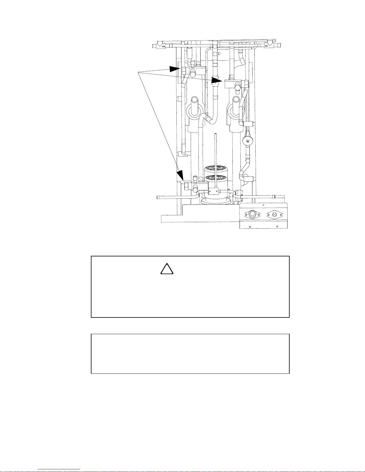
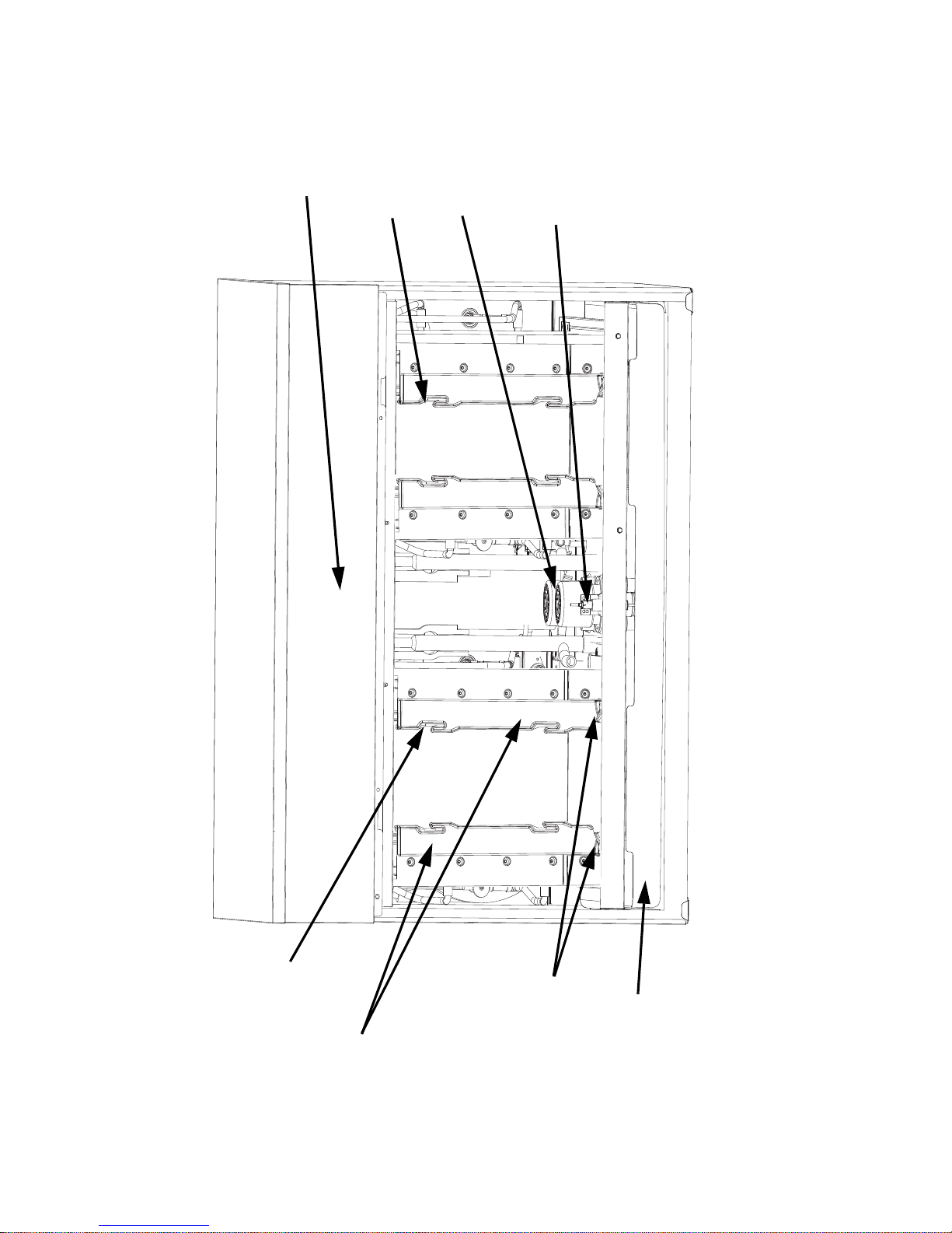
S3070C
WATER
PUMPS
WA TER LEVEL
PROBE
EV APORATORS
WATER
TROUGH
CONTROL
BOX
ICE DAMPERS
ICE
THICKNESS
PROBE
ICE
THICKNESS
PROBE
Page 71
Part Number 80-1505-3 6/11 71
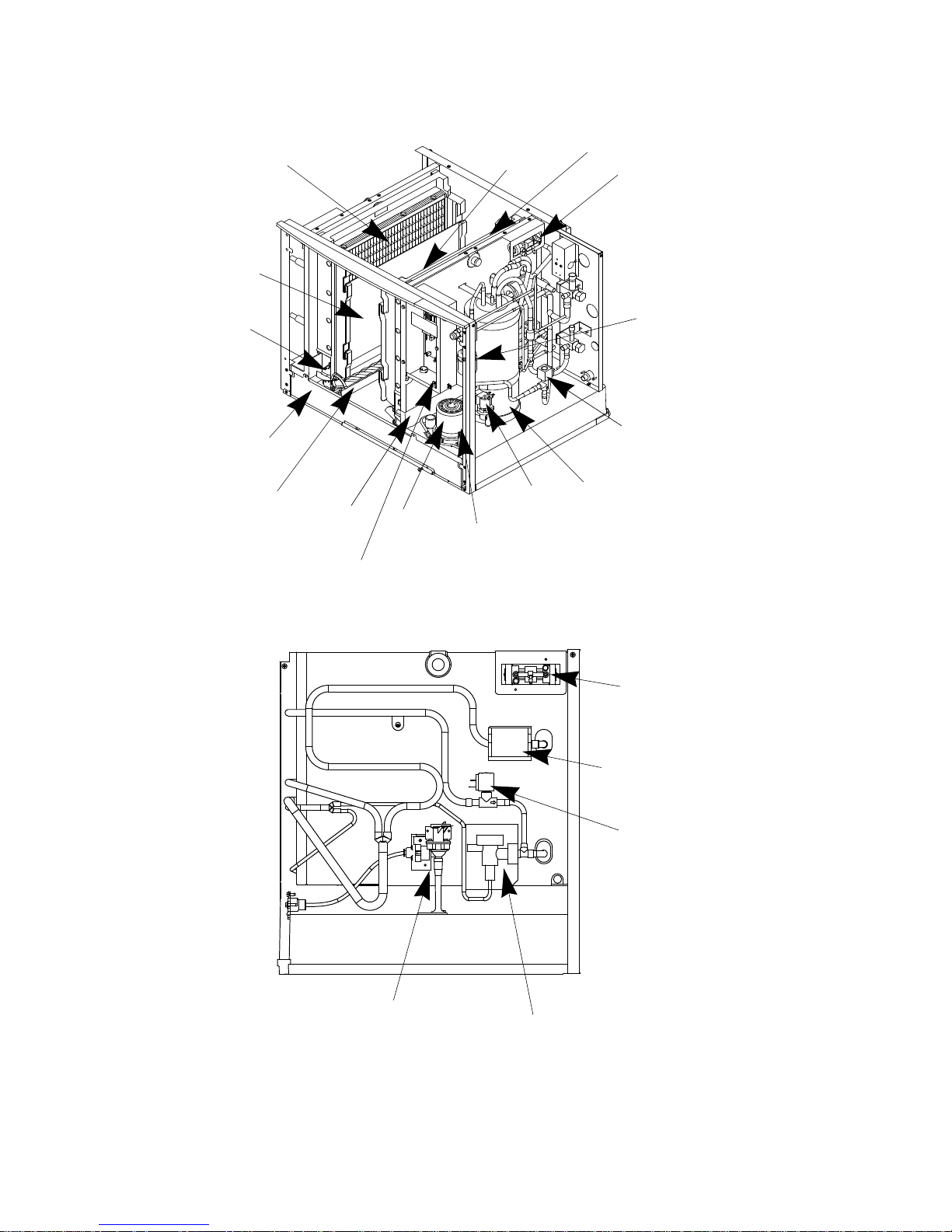
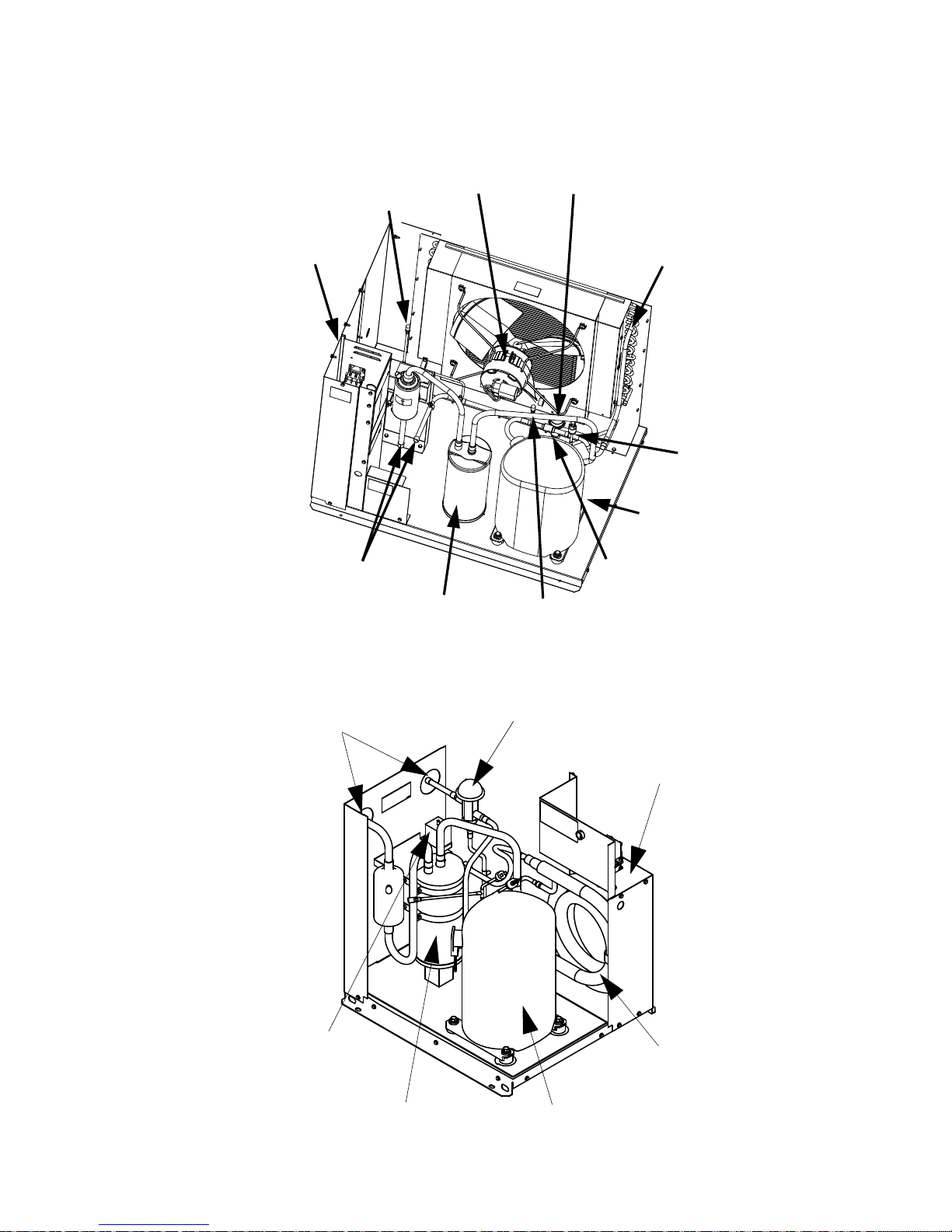
CVD® CONDENSING UNITS
CVD675/CVD685/CVD875/CVD885/CVD1075/CVD1085/
CVD1185/CVD1285/CVD1485
CVD1486
ACCESS
VALVE
CONDENSER
FAN MOTOR
HEAD PRESSURE
CONTROL VALVE
AIR
CONDENSER
COMPRESSOR
SUCTION
ACCUMULATOR
LIQUID LINE AND
SUCTION LINE
CONNECTION
POINTS
ELECTRICAL
COMPARTMENT
CHECK VALVE
ACCESS VALVE
LPCO
HEAD PRESSURE
CONTROL VALVE
ELECTRICAL
COMPARTMENT
COMPRESSOR
SUCTION
ACCUMULATOR
WATER
REGULA TING
VALVE
LIQUID LINE
AND SUCTION LINE
CONNECTION
POINTS
WATER
COOLED
CONDENSER
Page 72
72 Part Number 80-1505-3 6/11
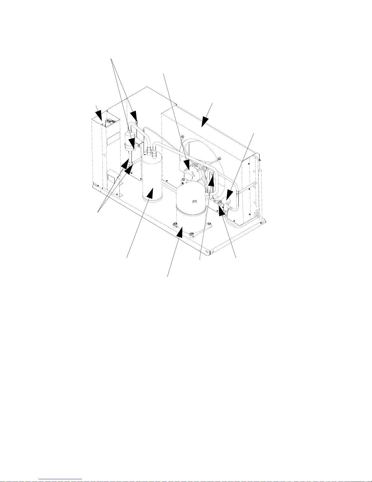
CVD1885/CVD2075/CVD2085/CVD3085
SUCTION
ACCUMULATOR
COMPRESSOR
LIQUID LINE
AND
SUCTION LINE
CONNECTION
POINTS
AIR
CONDENSER
HEAD PRESSURE
CONTROL VALV E
CONDENSER
FAN MOTOR
(CVD3085 HAS 2 FANS)
ACCESS
VALVES
ELECTRICAL
COMP.
CHECK VALVE
ACCESS VALVE
Page 73

Part Number 80-1505-3 6/11 73
Maintenance
General
Clean and sanitize the ice machine every six months
for efficient operation. If the ice machine requires more
frequent cleaning and sanitizing, consult a water care
professional to test the water quality and recommend
appropriate water treatment. An extremely dirty ice
machine must be taken apart for cleaning and
sanitizing.
Manitowoc Ice Machine Cleaner and Sanitizer are the
only products approved for use in Manitowoc ice
machines.
This Manitowoc Ice Machine has two separate
cleaning procedures.
Cleaning/Sanitizing Procedure
This procedure must be performed a minimum of once
every six months.
• The ice machine and bin must be disassembled
cleaned and sanitized
• All ice produced during the cleaning and sanitizing
procedures must be discarded
• Removes mineral deposits from areas or surfaces
that are in direct contact with water
Heavily Scaled Cleaning Procedure
Perform this procedure if you have some or all of these
symptoms.
• An IB600C/IB680C/IB800C/IB1000C
• Ice machine stops on Safety Shutdown
• Your water has a high concentration of minerals
• The ice machine has not been on a regular
maintenance schedule.
Page 74

74 Part Number 80-1505-3 6/11
Cleaning / Sanitizing Procedure
CLEANING PROCEDURE
Ice machine cleaner is used to remove lime scale and
mineral deposits. Ice machine sanitizer disinfects and
removes algae and slime.
NOTE: IB Models must be cleaned using the
procedure on page 91.
Step 1 Remove front door and top cover. This will
allow easiest access for adding cleaning and
sanitizing solutions.
!
Caution
Use only Manitowoc approved Ice Machine
Cleaner and Sanitizer for this application
(Manitowoc Cleaner part number 94-0546-3 and
Manitowoc Sanitizer part number 94-0565-3). It is
a violation of Federal law to use these solutions in
a manner inconsistent with their labeling. Read
and understand all labels printed on bottles
before use.
!
Caution
Do not mix Cleaner and Sanitizer solutions
together. It is a violation of Federal law to use
these solutions in a manner inconsistent with their
labeling.
!
Warning
Wear rubber gloves and safety goggles (and/or
face shield) when handling ice machine Cleaner
or Sanitizer.
Page 75

Part Number 80-1505-3 6/11 75
Step 2 Set the toggle switch to the OFF position after
ice falls from the evaporator at the end of a Harvest
cycle. Or, set the switch to the OFF position and allow
the ice to melt off the evaporator.
Step 3 Remove all ice from the bin.
Step 4 Place the toggle switch in the CLEAN
position. The water will flow through the water dump
valve and down the drain. Wait until the water trough
refills and water flows over the evaporator, then add
the proper amount of ice machine cleaner.
Step 5 Wait until the clean cycle is complete
(approximately *35 minutes). then place the toggle
switch in the OFF position and disconnect power to
the ice machine (and dispenser when used).
NOTE: *S307C Only - 80 minutes.
Step 6 Remove parts for cleaning.
Please refer to the proper parts removal for your
ice machine.
S600C/S680C/S850C/S1000C/S1200C - page 76.
S1470C/S1870C/S2070C/S2170C - page 77.
S3070C - page 80.
!
Caution
Never use anything to force ice from the
evaporator. Damage may result.
Model Amount of Cleaner
S0600C/S0680C/S0800C
S1000C/S1200C
5 ounces (150 ml)
S1470C/S1870C/
S2070C/S2170C
9 ounces (270 ml)
S3070C 16 ounces (475 ml)
!
Warning
Disconnect the electric power to the ice machine
at the electric service switch box.
Page 76

76 Part Number 80-1505-3 6/11
PARTS REMOVAL FOR CLEANING/
SANITIZING
S600C/S680C/S850C/S1000C/S1200C
A. Remove the water curtain
• Gently flex the curtain in the center and remove it
from the right side.
• Slide the left pin out.
B. Remove the ice thickness probe
• Compress the hinge pin on the top of the ice
thickness probe.
• Pivot the ice thickness probe to disengage one pin
then the other. The ice thickness probe can be
cleaned at this point without complete removal. If
complete removal is desired, disconnect the ice
thickness control wiring from the control board.
C. Remove the water trough
• Depress tabs on right and left side of the water
trough.
• Allow front of water trough to drop as you pull
forward to disengage the rear pins.
NOTE: Proceed to page 82, St ep 7.
A.
B.
C.
Page 77

Part Number 80-1505-3 6/11 77
S1470C/S1870C/S2170C
A. Remove Splash Shields.
• Grasp the top center of splash shields.
• Lift up and then out.
B. Remove ice thickness probe.
• Compress the hinge pin on the top of the ice
thickness probe.
• Pivot the ice thickness probe to disengage
one pin then the other. The ice thickness
probe can be cleaned at this point without
complete removal. If complete removal is
desired, disconnect the ice thickness control
wiring from the control board.
Page 78

78 Part Number 80-1505-3 6/11
C. Remove the water trough shield.
• Grasp the water trough shield in the center
and the left end.
• Flex th e water trough shie ld in the center and
pull the left end forward until clear of the side
wall. Repeat for the right end.
• Pull water trough shield forward to remove.
D. Remove the water trough.
• Depress the two tabs on the top of the water
trough.
• Turn left and right ice dampers down to clear
water trough.
• Pull forward on the water trough to remove.
NOTE: Proceed to page 82, St ep 7.
Page 79

Part Number 80-1505-3 6/11 79
A.
B.
C.
D.
Page 80

80 Part Number 80-1505-3 6/11
S3070C
A.Remove front evaporator shield.
• Remove four quarter turn connectors
• Remove splash shield
B.Remove Splash Shields.
NOTE: Each evaporator has a splash shield that must
be removed - total of four splash shields.
• Grasp the top center of splash shields.
• Lift up and then out.
C. Remove ice thickness probe.
• Compress the hinge pin on the top of the ice
thickness probe.
• Pivot the ice thickness probe to disengage one pin
then the other. The ice thickness probe can be
cleaned at this point without complete removal. If
complete removal is desired, disconnect the ice
thickness control wiring from the control board.
D. Remove the water pump assembly.
• Disconnect the vinyl distribution tube from both
water pumps.
• Disconnect the water pump and water level probe
electrical connections.
• After the wires are disconnected remove the two
thumbscrews and lift the water pump assembly out
of the ice machine.
E. Remove the water trough.
• Pull forward on the water trough to remove.
NOTE: Proceed to page 82, St ep 7.
Page 81

Part Number 80-1505-3 6/11 81
A
B
C
D
E
I
Page 82

82 Part Number 80-1505-3 6/11
Step 7 Mix a solution of cleaner and warm water.
Depending upon the amount of mineral buildup, a
larger quantity of solution may be required. Use the
ratio in the table below to mix enough solution to
thoroughly clean all parts.
Step 8 Use 1/2 of the cleaner/water mixture to clean
all components. The cleaner solution will foam when it
contacts lime scale and mineral deposits; once the
foaming stops use a soft-bristle nylon brush, sponge
or cloth (NOT a wire brush) to carefully clean the parts.
Soak parts for 5 minutes (15 - 20 minutes for heavily
scaled parts). Rinse all components with clean water.
Step 9 While components are soaking, use 1/2 of the
cleaner/water solution to clean all food zone surfaces
of the ice machine and bin (or dispenser). Use a nylon
brush or cloth to thoroughly clean the following ice
machine areas:
• Side walls
• Base (area above water trough)
• Evaporator plastic parts - including top, bottom,
and sides
• Bin or dispenser
Rinse all areas thoroughly with clean water.
Solution Type Water Mixed With
Cleaner 1 gal. (4 l)
16 oz (500 ml)
cleaner
Page 83

Part Number 80-1505-3 6/11 83
SANITIZING PROCEDURE
Step 10 Mix a solution of sanitizer and warm water.
Step 11 Use 1/2 of the sanitizer/water solution to
sanitize all removed components. Use a spray bottle
to liberally apply the solution to all surfaces of the
removed parts or soak the removed parts in the
sanitizer/water solution. Do not rinse parts after
sanitizing.
Step 12 Use 1/2 of the sanitizer/water solution to
sanitize all food zone surfaces of the ice machine and
bin (or dispenser). Use a spray bottle to liberally apply
the solution. When sanitizing, pay particular attention
to the following areas:
• Side walls
• Base (area above water trough)
• Evaporator plastic parts - including top, bottom and
sides
• Bin or dispenser
Do not rinse the sanitized areas.
Step 13 Replace all removed components.
Step 14 Wait 30 minutes.
Solution Type Water Mixed With
Sanitizer 6 gal. (23 l)
4 oz (120 ml)
sanitizer
Page 84

84 Part Number 80-1505-3 6/11
Step 15 Reapply power to the ice machine and place
the toggle switch in the CLEAN position.
Step 16 Wait until the water trough refills and water
flows over the evaporator (approximately 3 minutes).
Add the proper amount of Manitowoc Ice Machine
Sanitizer to the water trough by pouring between the
water curtain/splash shields and evaporator.
Step 17 Move the toggle switch to the ICE position
and replace the front panel. The ice machine will
automatically start ice making after the sanitize cycle
is complete (approximately 35 minutes,
S3070C - 80 minutes).
Model Amount of Sanitizer
S0600C/S0680C/S0800C
S1000C/S1200C
3 ounces (90 ml)
S1470C/S1870C/
S2070C/S2170C
12 ounces (355 ml)
S3070C 25 ounces (740 ml)
Page 85
Part Number 80-1505-3 6/11 85
Procedure to Clean Heavily Scaled
Ice Machines
IB models and Ice machines that are heavily scaled or
have not been cleaned on a regular basis will need to
run this procedure.
GENERAL
Clean and sanitize the ice machine every six months
for efficient operation. If the ice machine requires more
frequent cleaning and sanitizing, consult a qua lified
service company to test the water quality and
recommend appropriate water treatment. The ice
machine must be taken apart for cleaning and
sanitizing.
CLEANING PROCEDURE
!
Caution
Use only Manitowoc approved Ice Machine
Cleaner and Sanitizer for this application
(Manitowoc Cleaner part number 94-0546-3 and
Manitowoc Sanitizer part number 94-0565-3). It is
a violation of Federal law to use these solutions in
a manner inconsistent with their labeling. Read
and understand all labels printed on bottles
before use.
!
Caution
Do not mix Cleaner and Sanitizer solutions
together. It is a violation of Federal law to use
these solutions in a manner inconsistent with
their labeling.
!
Warning
Wear rubber gloves and safety goggles (and/or
face shield) when handling ice machine Cleaner
or Sanitizer.
Page 86
86 Part Number 80-1505-3 6/11
Ice machine cleaner is used to remove lime scale and
mineral deposits. Ice machine sanitizer disinfects and
removes algae and slime.
Step 1 Remove front door and top cover. This will
allow easiest access for adding cleaning and
sanitizing solutions.
Step 2 Set the toggle switch to the OFF position after
ice falls from the evaporator at the end of a Harvest
cycle. Or, set the switch to the OFF position and allow
the ice to melt off the evaporator.
Step 3 Remove all ice from the bin/dispenser.
Step 4 Place the toggle switch in the CLEAN
position. The water will flow through the water dump
valve and down the drain. Wait until the water trough
refills and water flows over the evaporator, then add
the proper amount of ice machine cleaner.
!
Caution
Never use anything to force ice from the
evaporator. Damage may result.
Model Amount of Cleaner
S0600C/S0680C/S0800C
S1000C/S1200C
5 ounces (150 ml)
IB620C/IB680C/
IB820C/IB1020C
5 ounces (150 ml)
S1470C/S1870C/
S2070C/S2170C
9 ounces (270 ml)
S3070C 16 ounces (475 ml)
Page 87

Part Number 80-1505-3 6/11 87
Step 5 Wait until the clean cycle is complete
(approximately *35 minutes) then place the toggle
switch in the OFF position and disconnect power to
the ice machine (and dispenser when used).
NOTE: *S3070C Only - 80 minutes.
Step 6 Remove parts for cleaning.
Please refer to the proper parts removal for your
ice machine.
S600C/S680C/S850C/S1000C/S1200C - page 88
IB620C/IB680C/IB820C/IB1020C - page 91
S1470C/S1870C/S2170C - page 95
S3070C - page 98
!
Warning
Disconnect the electric power to the ice machine
at the electric service switch box.
Page 88

88 Part Number 80-1505-3 6/11
PARTS REMOVAL FOR CLEANING/SANITIZING
S600C/S680C/S850C/S1000C/S1200C
A. Remove the water curtain
• Gently flex the curtain in the center and remove it
from the right side.
• Slide the left pin out.
B. Remove the ice thickness probe
• Compress the hinge pin on the top of the ice
thickness probe.
• Pivot the ice thickness probe to disengage one pin
then the other. The ice thickness probe can be
cleaned at this point without complete removal. If
complete removal is desired, disconnect the ice
thickness control wiring from the control board.
C. Remove the water distribution tube
NOTE: Distribution tube thumbscrews are retained to
prevent loss. Loosen thumbscrews but do not pull
thumbscrews out of distribution tube.
• Loosen the two outer screws (do not remove
screws completely they are retained to prevent
loss) and pull forward on the distribution tube to
release from slip joint.
• Disassemble distribution tube by loosening the two
(2) middle thumbscrews and dividing the
distribution tube into two pieces.
D. Remove the water trough
• Depress tabs on right and left side of the water
trough.
• Allow front of water trough to drop as you pull
forward to disengage the rear pins.
Page 89

Part Number 80-1505-3 6/11 89
E. Remove the water level probe
• Pull the water level probe straight down to
disengage.
• Lower the water level probe until the wiring
connector is visible.
• Disconnect the wire lead from the water level
probe.
• Remove the water level probe from the ice
machine.
F. Remove the water pump.
• Grasp pump and pull straight down on pump
assembly until water pump disengages and
electrical connector is visible.
• Disconnect the electrical connector.
• Remove the water pump assembly from ice
machine.
• Do not soak the water pump motor in cleaner or
sanitizer solution.
G. Remove the evaporator tray or water diverte r
from the bottom of the evaporator.
• Loosen thumbscrew on left side of tray.
• Allow left side of tray to drop as you pull the tray to
the left side. Continue until the outlet tube
disengages from the right side.
NOTE: Proceed to page 101, Step 7.
Page 90

90 Part Number 80-1505-3 6/11
A.
B.
C.
D.
E.
F.
G.
Page 91

Part Number 80-1505-3 6/11 91
IB620C/IB680C/IB820C/IB1020C
A. Remove the splash shield
• Remove quarter turn connector from the right side
of splash shield.
• Gently bow the center of the splash shield and lift
up and forward to remove.
B. Remove the water curtain
• Gently flex the curtain in the center and remove it
from the right side.
• Slide the left pin out.
C. Remove the ice thickness probe
• Compress the hinge pin on the top of the ice
thickness probe.
• Pivot the ice thickness probe to disengage one pin
then the other. The ice thickness probe can be
cleaned at this point without complete removal. If
complete removal is desired, disconnect the ice
thickness control wiring from the control board.
D. Remove the water level probe
• Loosen the screw that holds the water level probe
in place. The probe can easily be cleaned at this
point without complete removal. If complete
removal is desired, remove the top cover, left and
right side panels and control box cover. Disconnect
the wire lead from the control board inside the
electrical control box.
Important
Splash Shield must be reinstalled to prevent water
leakage.
Page 92

92 Part Number 80-1505-3 6/11
E. Remove the water trough
• Remove the quarter turn fasteners (turn
counterclockwise) securing the trough in place.
• Pull forward on the water trough until the rear pins
disengage from the water trough.
• Lift up and forward on the front of the water trough
while allowing the rear of the water trough to drop.
• Remove the water trough from the ice machine.
F. Remove the water distribution tube
• Remove the clamp from the vinyl water hose on
the right side of the distribution tube.
• Loosen the two thumbscrews which secure the
distribution tube.
• Lift the right side of the distribution tube up, and
then rotate it backward and to the right until the left
side of the distribution tube disengages the
thumbscrew.
• Pull the vinyl hose off the distribution tube.
Disassemble for cleaning:
• T wist both of the inner tube ends until the tabs line
up with the keyways.
• Pull the inner tube ends outward.
!
Caution
Do not force this removal. The lo cating tab must be
clear before rotating the distribution tube back.
Page 93

Part Number 80-1505-3 6/11 93
G. Remove the water pump.
• Note position of water pump outlet, and then
disconnect vinyl hose from the pump outlet.
• Rotate the thumbscrew that secures the pump to
the bulkhead 1/4 turn clockwise.
• Rotate the water pump assembly 1/4 turn
counterclockwise.
• Lower the pump assembly into the evaporator
compartment.
• Disconnect the water pump power cord.
• Remove water pump assembly from ice
machine.Do not soak the water pump motor in
cleaner or sanitizer solution
H. Remove the bin thermostat probe
• Loosen the 2 screws that holds the probe in place.
The probe can easily be cleaned at this point
without complete removal.
NOTE: Proceed to page 101, Step 7.
Page 94

94 Part Number 80-1505-3 6/11
A.
B.
C.
E.
F.
D.
G.
H.
Page 95

Part Number 80-1505-3 6/11 95
S1470C/S1870C/S2070C/S2170C
A. Remove Splash Shields.
• Grasp the top center of splash shields.
• Lift up and then out.
B. Remove ice thickness probe.
• Compress the hinge pin on the top of the ice
thickness probe.
• Pivot the ice thickness probe to disengage one pin
then the other. The ice thickness probe can be
cleaned at this point without complete removal. If
complete removal is desired, disconnect the ice
thickness control wiring from the control board.
C. Remove distribution tubes.
• Distribution tubes thumbscrews are retained to
prevent loss. Loosen thumbscrews but do not pull
thumbscrews out of distribution tube.
• Loosen the two outer screws and pull forward on
the distribution tube to release from slip joint.
• Disassemble distribution tube by loosening the two
(2) middle thumbscrews and dividing the
distribution tube into two pieces.
D. Remove the water trough shield.
• Grasp the water trough shield in the center and the
left end.
• Flex the water trough shield in the center and pull
the left end forward until clear of the side wall.
Repeat for the right end.
• Pull water trough shield forward to remove.
Page 96

96 Part Number 80-1505-3 6/11
E. Remove ice dampers.
• Grasp ice damper and apply pressure toward the
back mounting bracket.
• Apply pressure to the front mounting bracket with
thumb.
• Pull ice damper downward when the front ice
damper pin disengages.
F. Remove the water pump assembly.
• Disconnect the vinyl distribution tube from the
water pump.
• Disconnect the water pump and water level probe
electrical connections.
• After the wires are disconnected squeeze the two
tabs and lift the water pump assembly out of the
ice machine.
• Do not immerse the water pump motor in cleaner
or sanitizer solutions.
G. Remove the water trough.
• Depress the two tabs on the top of the water
trough.
• Turn left and right ice dampers down to clear water
trough.
• Pull forward on the water trough to remove.
NOTE: Proceed to page 101, Step 7.
Page 97
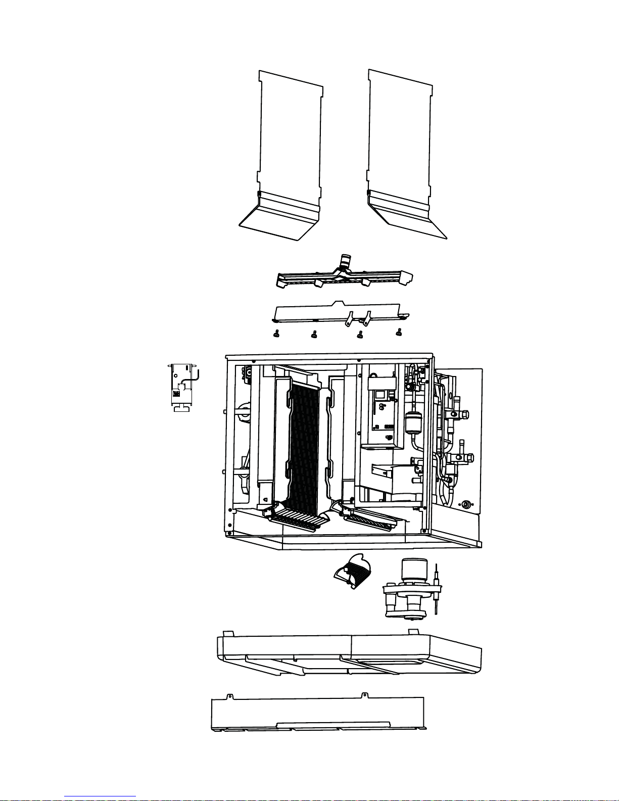
Part Number 80-1505-3 6/11 97
A.
B.
C.
D.
F.
G.
E.
Page 98

98 Part Number 80-1505-3 6/11
S3070C
A.Remove front evaporator shield.
• Remove four quarter turn connectors
• Remove splash shield
B.Remove left and right evaporator top covers.
• Remove two thumbscrews from the front of each
evaporator top cover.
• Lift front of cover, pull forward to remove.
C.Remove Splash Shields.
NOTE: Each evaporator has a splash shield that must
be removed - total of four splash shields.
• Grasp the top center of splash shields.
• Lift up and then out.
D. Remove ice thickness probe.
• Compress the hinge pin on the top of the ice
thickness probe.
• Pivot the ice thickness probe to disengage one pin
then the other. The ice thickness probe can be
cleaned at this point without complete removal. If
complete removal is desired, disconnect the ice
thickness control wiring from the control board.
Page 99

Part Number 80-1505-3 6/11 99
E. Remove distribution tubes.
NOTE: Each evaporator has a distribution that must
be removed - total of four distribution tubes.
• Distribution tube thumbscrews are retained to
prevent loss. Loosen thumbscrews but do not pull
thumbscrews out of distribution tube.
• Loosen the two outer screws and pull forward on
the distribution tube to release from slip joint.
• Disassemble distribution tube by loosening the two
(2) middle thumbscrews and dividing the
distribution tube into two pieces.
F. Remove ice dampers.
NOTE: Each evaporator has an ice damper that must
be removed - total of four ice dampers
• Grasp ice damper and apply pressure toward the
back mounting bracket.
• Apply pressure to the front mounting bracket with
thumb.
• Pull ice damper downward when the front ice
damper pin disengages.
G. Remove the water pump assembly.
• Disconnect the vinyl distribution tube from both
water pumps.
• Disconnect the water pump and water level probe
electrical connections.
• After the wires are disconnected remove the two
thumbscrews and lift the water pump assembly out
of the ice machine.
• Remove the thumbscrews securing the water
pumps (2 each pump) and remove water pumps.
Do not immerse the water pump motor in cleaner
or sanitizer solutions.
• Remove the water level probe from the assembly
housing.
H. Remove the water trough.
• Pull forward on the water trough to remove.
NOTE: Proceed to page 101, Step 7.
Page 100

100 Part Number 80-1505-3 6/11
A
B
C
D
E
F
G
H
 Loading...