

Page 1

Manitowoc
Ice Machine Parts List for
Series G-0800 Cuber Models
GR-0800A
GD-0802A
GD-0892N
GY-0805W
GR-0801W
Manufactured October 1984 through August 1992
GD-0803W
GY-0804A
GY-0894N
R-502 System
G0800 – 1
Updated: 10/10
Page 2
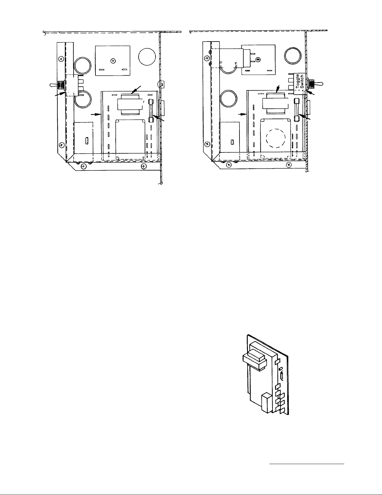
G-0800 CONTROL BOX
1231
4
7
1
Transformer
Board
Sensor
Module
High
Pressure
Control
Water
Pump
Delay
Timer
Toggle
Switch
Water
Pump Delay
5
2
6
8
2
High
Pressure
Control
Sensor
Module
6
Transformer
Board
5
7
1
4
Low
Pressure
Control
3
8
CONTROL BOX - AIR & CONTROL BOX - REMOTE UNITS
UNITIZED SENSOR BOARD
#76-2375-3
CONTROL BOX PART NO.
1 Fuse . . . . . . . . . . . . . . . . . . . . . . . . . . . . . . . . . . . . . . . . . . . . . . . . . . . . . . . . . . . . . . . . . . . . . . . . . . † 25-1037-9
2 High Pressure Control Up to SN 870860000 . . . . . . . . . . . . . . . . . . . . . . . . . . . . . . . . . . . . . . . . . . . 23-5521-3
2a High Pressure Control After SN 870860000. . . . . . . . . . . . . . . . . . . . . . . . . . . . . . . . . . . . . . . . . . . . † 23-5524-3
3 Low Pressure Control Up to SN 870860000. . . . . . . . . . . . . . . . . . . . . . . . . . . . . . . . . . . . . No Longer Available
3a Low Pressure Control After SN 870860000 . . . . . . . . . . . . . . . . . . . . . . . . . . . . . . . . . . . . . . . . . . . . 23-5527-3
4 Main Toggle Switch. . . . . . . . . . . . . . . . . . . . . . . . . . . . . . . . . . . . . . . . . . . . . . . . . . . . . . . . . . . . . . . † 23-0084-9
5 Mounting Track for Transformer Board. . . . . . . . . . . . . . . . . . . . . . . . . . . . . . . . . . . . . . . . . . . . . . . . 44-0801-3
6 Sensor Module Use . . . . . . . . . . . . . . . . . . . . . . . . . . . . . . . . . . . . . . . . . . . . . . . . . . . . . . . . . . . . . . † 76-2375-3
7 Transformer Board 230V Use. . . . . . . . . . . . . . . . . . . . . . . . . . . . . . . . . . . . . . . . . . . . . . . . . . . . . . . † 76-2375-3
8 Timer - Pump Delay Up to SN 870960837 (Using siphon). . . . . . . . . . . . . . . . . . . . . . . . . . . . . . . . . † 24-0642-3
8a Interval Timer After SN 870960837 (Using dump valve) . . . . . . . . . . . . . . . . . . . . . . . . . . . . . . . . . . † 24-0643-3
9 Water Shield Used When Stacking. . . . . . . . . . . . . . . . . . . . . . . . . . . . . . . . . . . . . . . . . . . . . . . . . . . 76-2388-3
Unitized sensor board is used to replace both the transformer board and sensor module . . . . . . . † 76-2375-3
† Refer to Cross Reference Guide
Updated: 6/08
G0800 – 2
Page 3
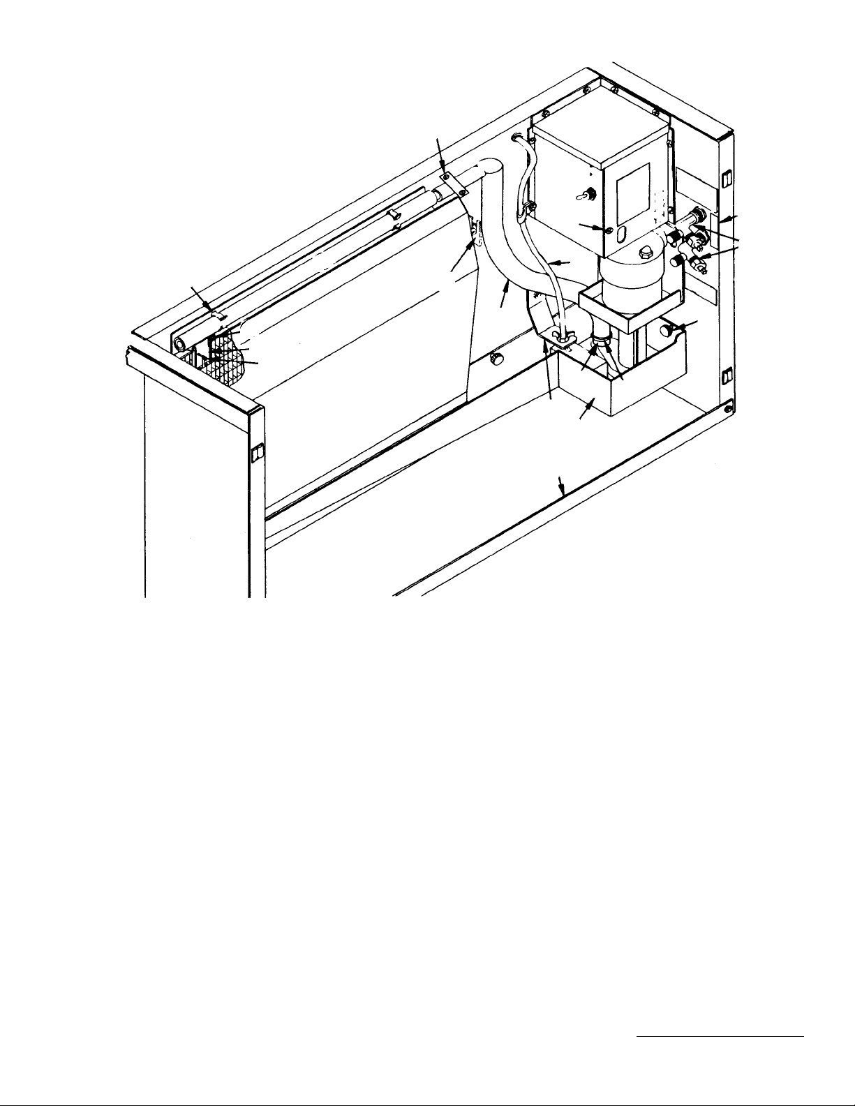
G-0800 WATER DISTRIBUTION
1232
5
27
13
16
17, 18
20
32, 33
26
22
15
23
21
11
12
4
24
10
34
35
36
28
2
3
EVAPORATOR AND WATER
DISTRIBUTION PART NO.
1 Activating Pin Assembly. . . . . . . . . . . 76-2025-3
2 Control Box Front Cover . . . . . . . . . . † 76-2150-3
3 Control Box Top Cover. . . . . . . . . . . . † 660771-4
4 Distribution Tube Assembly . . . . . . . . 76-2162-3
5 Distribution Tube Spring Clip . . . . . . . † 56-5047-9
6 Evaporator, Regular Cube . . . . . . . .
No Longer Available
7 Evaporator, Dice Cube. . . . . . . . . . No Longer Available
8 Evaporator, Half Dice Cube . . . . . . . . † 76-2073-9
9 Float Valve. . . . . . . . . . . . . . . . . . . . . † 83-6905-9
10 Float Valve Bracket . . . . . . . . . . . . . . † 76-2140-3
11 Ice Thickness Control. . . . . . . . . . . . . † 76-1996-3
12 Ice Thickness Control - Bracket. . . . . 618581-4
Ice Thickness Control Screw . . . . . . . † 50-2237-9
13 Label (For high and low side
service valve). . . . . . . . . . . . . . . . . . † 81-3147-3
14 Nylon Nut (For mounting 43-0201-3). † 54-2945-9
15 Screw 10-24 Phillips Head
(Pkg. of 12) . . . . . . . . . . . . . . . . . . . † 52-0205-9
16 Service Valve, High and Low Side . . . † 83-7310-9
17 Sump Trough (Units using siphon). . . 684234-4
18 Sump Trough (Units using
dump valve). . . . . . . . . . . . . . . . . . . † 687791-9
Overflow Tube in Sump Trough. . . . . 44-2056-3
19 Sump Trough Support Pin . . . . . . . . . † 43-0201-9
20 Support Angle, Front . . . . . . . . . . . . . † 658031-9
PART NO.
21 Thumb Screw for Ice
Thickness Control . . . . . . . . . . . . . . † 50-1210-9
22 Thumb Screw (Mounting
sump trough) . . . . . . . . . . . . . . . . . . † 53-0504-9
23 Tubing, Polyflow
(Fresh water inlet to float valve) . . . 44-2029-1
24 Water Curtain. . . . . . . . . . . . . No Longer Available
25 Water Curtain Hanger
(White plastic) . . . . . . . . . . . . . . . . . † 56-5045-9
26 Water Curtain Side Bracket
(Set of left and right hand). . . . . . . . † 76-2177-3
27 Water Flow Clamp Assembly. . . . . . . 76-2054-3
28 Water Pump 50/60 Hz 220V . . . . . . . † 76-2601-3
29 Water Inlet Strainer . . . . . . . . . . . . . . † 12-6003-3
30 Water Pump Lead w/ Female Plug
31 Water Siphon Tube Assembly
32 Pump Discharge Tube Assembly
(See Page 4) . . . . . . . . . . . . . . . . . . 76-2091-3
(Siphon). . . . . . . . . . . . . . . . . . . . .
No Longer Available
No Longer Available
33 Pump Discharge Tube Assembly
(Dump valve). . . . . . . . . . . . . . . . . . † 44-2033-3
34 Pump Discharge Tube Clamp . . . . . . † 56-5053-9
35 Reducer Assembly. . . . . . . . . . . . . . . 76-2377-3
36 Barbed Tee. . . . . . . . . . . . . . . . . . . . . 83-9102-3
† Refer to Cross Reference Guide
G0800 – 3
Updated: 10/10
Page 4
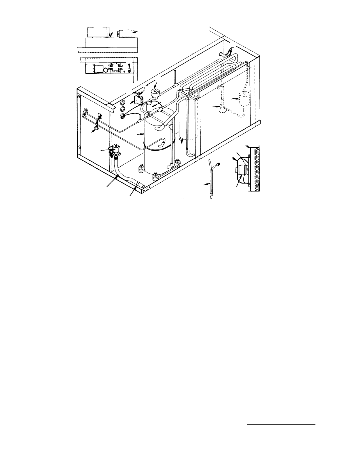
G-0800 AIR-COOLED
1233
5
27
4
26
START COMPONENT BOX
36
17
29
36, 37
39
40
1
15
11
25
23
7
30
20
19
21
12
22, 34
31, 35
24, 32
14
Used only on units
without dump solenoid.
2
AIR-COOLED PART NO.
1 Compressor Assembly 1 Phase,
60 Hz 220V . . . . . . . . . . . . . . . . . . . † 76-2815-3
1a Compressor Assembly 3 Phase . . . . . † 76-2816-3
2 Contactor - 1 Phase . . . . . . . . . . . . . . † 24-1016-9
2a Contactor - 3 Phase . . . . . . . . No Longer Available
3 Delay Timer (Air and water) . . . . . . . . † 24-0635-3
4 Run Capacitor. . . . . . . . . . . . . . . . . . . . See Page 9
5 Start Capacitor . . . . . . . . . . . . . . . . . . .See Page 9
6 Start Relay . . . . . . . . . . . . . . . . . . . . . . See Page 9
7 Accumulator . . . . . . . . . . . . No Longer Available
8 Adapter (Fresh water inlet). . . . . . . . . 600242-1
9 Adapter, Inlet Union . . . . . . . . . . . . . . 13-6096-1
10 Adapter, Sump Drain . . . . . . . . . . . . . 17-0602-1
11 Activating Pin Assembly. . . . . . . . . . . 76-2025-3
12 Air Condenser with Shroud. . . No Longer Available
13 Air Condenser Only . . . . . . . . No Longer Available
14 Bin Switch. . . . . . . . . . . . . . . . . . . . . . † 23-0111-9
15 Bin Switch Bracket . . . . . . . . . . . . . . . 617531-4
16 Bin Switch Mylar Insulation. . . . . . . . . 619961-4
17 Cable Clamp, Nylon . . . . . . . . . . . . . . † 56-5004-9
18 Drain Overflow Tube. . . . . . . . . . . . . . † 626511-4
19 Drier . . . . . . . . . . . . . . . . . . . . . . . . . . † 89-3027-9
20 Expansion Valve . . . . . . . . . . . . . . . . . † 76-2707-3
21 Expansion Valve Stainless Steel
Bulb Clamp. . . . . . . . . . . . . . . . . . . . † 56-5052-9
22 Fan Blade Prior to SN 870260500
For Motors ESP-OL5OEM2 and
ESP-OL5OEM28 . . . . . . . . . . . . . . . 24-1608-3
NOTE: FOR 50 CYCLE PARTS, SEE PAGE 8
22a Fan Blade Prior to SN 870260500 For
Fan Motor K33HXCEJ-948 . . . . . . . 24-1617-3
23 Fan Cycle Control. . . . . . . . . . . . . . . . 23-0115-3
24 Fan Motor Prior to SN 870260500 . . . † 76-2638-3
25 Hot Gas Solenoid Valve Assembly . . . 24-0433-3
26 Run Capacitor Bracket . . . . . . . . . . . . 623341-4
27 Start Capacitor Bracket. . . . . . . . . . . . 85-0309-3
28 Tubing, 5/8" ID . . . . . . . . . . . . . . . . . . † 44-2038-3
29 Water Pump Female Lead . . No Longer Available
30 Water Siphon Assembly . . . . . . . . . . . 76-2091-3
31 Motor Mounting Bracket Up to
SN 870260500. . . . . . . . . . . . . . . . . 34-0621-3
32 Fan Motor After SN 870260500 . . . . . 24-1243-3
33 Fan Capacitor After SN 870260500 . .
No Longer Available
34 Fan Blade After SN 870260500 . . . . . 24-1612-3
35 Motor Mounting Bracket After
SN 870260500. . . . . . . . . . . . . . . . . 34-0616-3
To Retrofit New Fan Motor To Ice Machines
Prior to SN 870260500 Use. . . . . . . 76-2286-3
36 Water Dump Solenoid
Coil Only (Dole) . . . . . . . . . . . . . . . . 24-0464-3
37 Water Dump Solenoid
(Alco) . . . . . . . . . . . . . . . . . . . . . . . . 000001768
38 Air Baffle (Not shown). . . . . . . . . . . . . † 76-2195-3
39 Vinyl Tubing . . . . . . . . . . . . . . . . . . . . † 44-2033-3
40 Hose Clamp . . . . . . . . . . . . . . . . . . . . † 56-5060-9
To Replace Siphon With Water Dump
Solenoid Use Refrofit. . . . . . . . . . . . † 76-2308-3
PART NO.
Updated: 10/10
G0800 – 4
† Refer to Cross Reference Guide
Page 5

G-0800 WATER-COOLED
1234
28
24
5
23
4
21
START COMPONENT BOX
3
6
2
14
22
10
15
12
11
19
20
26
27
17
1
25
7
16
18
WATER-COOLED PART NO.
1 Compressor Assembly, 60 Hz 220V . † 76-2815-3
2 Contactor . . . . . . . . . . . . . . . . . . . . . . † 24-1016-9
3 Delay Timer (Air and water). . . . . . . . † 24-0635-3
4 Run Capacitor . . . . . . . . . . . . . . . . . . . See Page 9
5 Start Capacitor. . . . . . . . . . . . . . . . . . . See Page 9
6 Start Relay . . . . . . . . . . . . . . . . . . . . . . See Page 9
7 Accumulator
. . . . . . . . . . . . . . . . . . . . . . . . . . No Longer Available
8 Activating Pin Assembly. . . . . . . . . . . 76-2025-3
9 Adapter, Fresh Water Inlet . . . . . . . . . 600242-1
10 Adapter, Sump Drain . . . . . . . . . . . . . 17-0602-1
11 Bin Switch . . . . . . . . . . . . . . . . . . . . . † 23-0111-9
12 Bin Switch Bracket. . . . . . . . . . . . . . . 617531-4
13 Bin Switch Mylar Insulation . . . . . . . . 619961-3
14 Cable Clamp, Nylon. . . . . . . . . . . . . . † 56-5004-9
15 Drain Overflow Tube . . . . . . . . . . . . . † 626511-4
NOTE: FOR 50 CYCLE PARTS, SEE PAGE 8
PART NO.
16 Drier. . . . . . . . . . . . . . . . . . . . . . . . . . † 89-3027-9
17 Expansion Valve. . . . . . . . . . . . . . . . . † 76-2707-3
18 Expansion Valve Stainless Steel
Bulb Clamp . . . . . . . . . . . . . . . . . . . † 56-5052-9
19 Hot Gas Solenoid Valve Assembly. . . 24-0433-3
20 Receiver. . . . . . . . . . . . . . . . . . . . . . . 12-0003-1
21 Run Capacitor Bracket. . . . . . . . . . . . 623341-4
22 Screw 10-24 Slot Head . . . . . . . . . . . † 52-0205-9
23 Start Capacitor Bracket . . . . . . . . . . . 85-0309-3
24 Tubing, 5/8" ID. . . . . . . . . . . . . . . . . . † 44-2038-3
25 Water Condenser . . . . . . . . . . . . .
26 Water Condenser Outlet Adapter. . . . 87-0610-3
27 Water Regulator. . . . . . . . . . . . . . . . . † 83-7206-9
28 Water Pump Female Lead. . . . . . .
No Longer Available
No Longer Available
G0800 – 5
† Refer to Cross Reference Guide
Updated: 10/10
Page 6

G-0800 REMOTE UP TO SN 880960000
1235
22
8
26
28
14
7
25
29
6
16
20
10
11
17
26
19
18
30
1
15
4
27
24
3
START COMPONENT BOX
5
9
2
23
REMOTE SYSTEM
COMPRESSOR COMP ARTMENT PART NO.
1 Compressor Assembly 1 Phase,
60 Hz 220V . . . . . . . . . . . . . . . . . . . † 76-2815-3
2 Contactor . . . . . . . . . . . . . . . . . . . . . . † 24-1016-9
3 Run Capacitor. . . . . . . . . . . . . . . . . . . . See Page 9
4 Start Capacitor . . . . . . . . . . . . . . . . . . .See Page 9
5 Start Relay . . . . . . . . . . . . . . . . . . . . . . See Page 9
6 Accumulator . . . . . . . . . . . . . No Longer Available
7 Adapter, Sump Drain . . . . . . . . . . . . . 17-0602-1
8 Bin Switch. . . . . . . . . . . . . . . . . . . . . . † 23-0111-9
9 Cable Clamp, Nylon . . . . . . . . . . . . . . † 56-5004-9
10 Coupling . . . . . . . . . . . . . . . . . . . . . . . † 83-6037-3
11 Coupling . . . . . . . . . . . . . . . . . No Longer Available
12 Coupling “0” Ring for 83-6037-3. . . . . † 83-6022-9
13
Coupling “0” Ring for Male Coupling, 1-1/8" x 3/8 OD . † 83-6023-9
14 Drain Overflow Tube. . . . . . . . . . . . . . † 626511-4
15 Drier . . . . . . . . . . . . . . . . . . . . . . . . . . † 89-3027-9
16 Expansion Valve . . . . . . . . . . . . . . . . . † 76-2707-3
17 Expansion Valve Stainless Steel
Bulb Clamp. . . . . . . . . . . . . . . . . . . . † 56-5052-9
18 Heater (On discharge line) . . . . . . . . . † 76-2013-3
19 Hot Gas Solenoid Valve Assembly . . . 24-0433-3
20 Liquid Line Pump Down Valve
Assembly 208/230V 50/60 Hz
(Danfoss) . . . . . . . . . . . . . . . . . . . . . † 76-3008-1
21 Liquid Line Pump Down Valve
Coil Only Alco . . . . . . . . . . . . . . . . . † 24-0448-3
22 Pressure Limiter Switch . . . . . No Longer Available
23 Receiver . . . . . . . . . . . . . . . . . . . . . . . † 76-2958-3
24 Run Capacitor Bracket . . . . . . . . . . . . 623341-4
25 Screw 10-24 x 5/8" . . . . . . . . . . . . . . . † 52-0205-9
26 Service Valve For Receiver . . . . . . . . † 83-7316-9
27 Start Capacitor Bracket. . . . . . . . . . . . 85-0309-3
28 Tubing, 5/8" ID . . . . . . . . . . . . . . . . . . † 44-2038-3
29 Water Siphon Assembly . . . . . . . . . . . 76-2091-3
30 3 Phase Compressor . . . . . . . . . . . . . 76-2180-3
PARTS LOCATED IN REMOTE CONDENSER
Fan Motor. . . . . . . . . . . . . . . . . . . . . . . . . . † 76-1984-3
Head Pressure Control. . . . . . . . . . . . . . . . † 83-6806-9
Female Coupling Kit. . . . . . . . . . . . . . . . . . 07-0066-3
NOTE: FOR 50 CYCLE PARTS, SEE PAGE 8
PART NO.
Updated: 10/10
† Refer to Cross Reference Guide
G0800 – 6
Page 7

G-0800 REMOTE AFTER SN 880960000
1236
25
1
11
19
10
16
3
17
18
6
26
17
15
14
8
21
22
23
24
12
9
4
5
20
13
2
7
PA RT NO.
1 Bin Switch . . . . . . . . . . . . . . . . . . . . . † 23-0111-9
2 Bin Switch Bracket. . . . . . . . . . . . . . . 617531-4
3 Check Valve. . . . . . . . . . . . . . . . . . . . † 83-7314-9
4 Compressor Assembly, 1 PH 60 Hz
220V . . . . . . . . . . . . . . . . . . . . . . . . † 76-2815-3
5 Compressor Assembly, 3 Phase . . . . † 76-2816-3
6 Coupling Assembly, 1/2" . . . . . . . . . . † 83-6037-3
7 Coupling Assembly, 3/8" . . . . . . . .
8 Drain Fitting . . . . . . . . . . . . . . . . . . . . 17-0602-1
9 Expansion Valve. . . . . . . . . . . . . . . . . † 76-2707-3
10 Harvest Pressure Expansion Valve . . 83-6731-3
No Longer Available
11 Low Pressure Control - Pump Down . 23-5527-3
12 Process Valve . . . . . . . . . . . . . . . . . . † 83-7310-9
13 Receiver. . . . . . . . . . . . . . . . . . . . . . . † 76-2958-3
13a Receiver Mounting Bracket . . . . . . . . 600056-1
14 Receiver Safety Plug . . . . . . . . . . . . . † 628451-9
15 Receiver Service Valve . . . . . . . . . . . † 83-7316-9
16 Solenoid Valve, Hot Gas . . . . . . . . . . 24-0433-3
17 Solenoid Valve, Liquid Line or Harvest
Assist 208/230V 50/60 Hz
(Danfoss). . . . . . . . . . . . . . . . . . . . . † 76-3008-1
18 Stainless Steel Worm Drive Clamp . . † 56-5052-9
19 Suction, Pressure Cut-out Switch . .
No Longer Available
20 Tee, Barbed . 83-9102-3
21 Tube, 5/8" OD x 2" Long . . . . . . . . . . 623451-4
22 Tubing, 1/2" 1D x 3/4" OD . . . . . . . . . † 44-2033-3
23 Water Dump Solenoid Valve . . . . . . . † 24-0462-9
24 Dump Valve Bracket. . . . . . . . . . . . . . 626031-4
25 Water Pump Lead . . . . . . . . . . . . .
No Longer Available
26 Drier. . . . . . . . . . . . . . . . . . . . . . . . . . † 89-3027-9
NOTE: FOR 50 CYCLE PARTS, SEE PAGE 8
PART NO.
† Refer to Cross Reference Guide
G0800 – 7
Updated: 10/10
Page 8

G-0800 OUTER PANELS
1237
7, 8, 9
11
4
23
12
1
22
24
5
15, 20
16, 21
13, 18
14, 19
2
COMMON PARTS PART NO.
1 Front Support Angle . . . . . . . . . . . . . . † 658031-9
2 Front Panel Trim. . . . . . . . . . . . . . . . . † 81-3137-3
3 Front Panel Seal. . . . . . . . . . . . . . . . . † 92-0250-9
4 Front Panel Catches Only
(Pkg. of 12). . . . . . . . . . . . . . . . . . . . 76-2064-3
5 Front Panel Strike Only (Pkg. of 25). . 76-2063-3
6 Front Panel Strike-n-Catch
(Pkg. of 4 each) . . . . . . . . . . . . . . . . 76-2029-3
7 Rear Panel (Air-cooled) . . . . . . . . . . . 76-2020-3
8 Rear Panel (Water-cooled). . . . . . . . . 76-2021-3
9 Rear Panel (Remote) . . . . . . . . . . . . . 76-2022-3
10 #10-24 Phillips Head Screw (Mounting
control box cover) (Pkg. of 12). . . . . † 52-0205-9
11 #10-24 Slot Head Screw (Mounting
outer panels) (Pkg. of 12). . . . . . . . . † 52-0206-9
12 #10-24 Phillips Head Screw (Mounting
front angle support) (Pkg. of 12) . . . † 52-0209-9
OUTER PANELS - FAWN PART NO.
13 Front Panel - Textured Fawn . No Longer Available
14 Left Hand End Panel. . . . . . . No Longer Available
15 Right Hand End Panel . . . . . . No Longer Available
16 Top Cover - Fawn. . . . . . . . . . . . . . . . 683851-4
17 Fawn Touch Up Paint . . . . . . . . . . . . . 94-0093-1
OUTER PANELS - STAINLESS STEEL
18 Front Panel. . . . . . . . . . . . . . . . . . . . . 76-2158-3
18 Front Panel - McDonalds . . . No Longer Available
19 Left Hand End Panel. . . . . . . . . . . . . . † 686153-4
20 Right Hand End Panel . . . . . . . . . . . . † 76-2159-3
21 Top Cover - Stainless . . . . . . . No Longer Available
LATE PRODUCTION FRONT PANEL
22 Front Panel Screw . . . . . . . . . . . . . . . † 50-2668-9
23 Cage Nut . . . . . . . . . . . . . . . . . . . . . . † 54-2910-9
24 Hole Plug (Black) . . . . . . . . . . . . . . . . † 43-0155-9
25 Spacer for Front Panel Screw. . . . . . . † 37-1819-9
MODEL G-0800 50 HZ MODELS ONLY PART NO.
Use same parts as previously listed for standard G-0800 except for the following:
Compressor Assembly . . . . . . . . . . . . . . . . . . . . . . . . . . . . . . . . . . . . . . . . . . . . . . . . . . . . . . . . . . . . . . . . † 76-2817-3
Compressor Start Components . . . . . . . . . . . . . . . . . . . . . . . . . . . . . . . . . . . . . . . . . . . . . . . . . . . . . . . . . . See Page 9
Remote Fan Motor - (Located in remote condenser unit). . . . . . . . . . . . . . . . . . . . . . . . . . . . . . . . . . . . . . † 76-1985-3
Control Board . . . . . . . . . . . . . . . . . . . . . . . . . . . . . . . . . . . . . . . . . . . . . . . . . . . . . . . . . . . . . . . . . . . . . . . † 76-2396-3
Updated: 2/10
† Refer to Cross Reference Guide
G0800 – 8
Page 9

COMPRESSOR COMPONENTS FOR G-0800
230V/60 HZ/1 PH
Start Start Run
Compressor Model Number Relay Capacitor Capacitor
Tecumseh AB5524G . . . . . . . . . . . . . . . . . . . . . . . . † 20-0799-3 † 85-0314-3
Bristol M52B143BBCB. . . . . . . . . . . . . . . . . . . . . . . † 76-2611-3 85-0364-3 20-1014-3
Bristol M53B143BBCB. . . . . . . . . . . . . . . . . . . . . . . 85-0425-3 85-0314-3
Tecumseh AWA7512ZXD . . . . . . . . . . . . . . . . . . . . 20-0757-9 85-0551-3 † 20-1013-3
230V/50 HZ/1 PH
Start Start Run
Compressor Model Number Relay Capacitor Capacitor
Tecumseh AB5530G . . . . . . . . . . . . . . . . . . . . . . . . 85-0362-3 † 85-0314-3
Bristol H25B32QABHB . . . . . . . . . . . . . . . . . . . . . . 20-0755-9 85-0441-3 † 000000028
Bristol M52B183BBCB. . . . . . . . . . . . . . . . . . . . . . . 85-0392-3 85-0364-3 85-0393-3
Tecumseh AWA7512ZXC . . . . . . . . . . . . . . . . . . . . 85-0561-3 85-0383-3 † 20-1013-3
No Longer Available
No Longer Available
No Longer Available
G0800 – 9
† Refer to Cross Reference Guide
Updated: 9/10
Page 10

REMOTE CONDENSER AC-0895
1238
25
30
29
26
27
28
9
8
15, 16, 25
17, 18, 25
7
5
11
23
24
13
12
31
23
2, 4
1
19, 20,
21, 22
10
6
11
24
23
15
PA RT NO.
1 Air Condenser. . . . . . . . . . . . . . . . . . . † 88-5062-9
2 Fan Motor, 60 Hz 230V*. . . . . . . . . . . † 76-2941-3
3 Run Capacitor (Emerson)* . . . . . . . . . 85-0335-3
3a Run Capacitor (Magnatec) . . . . . . .
No Longer Available
4 Fan Blade* . . . . . . . . . . . . . . . . . . . . . 24-1611-3
5 Fan Motor 50 Hz 230V* . . . . . . . . . . . † 76-2941-3
6 Rain Shield* . . . . . . . . . . . . . . . . . . . . 24-1505-3
7 Head Pressure Control. . . . . . . . . . . . † 83-6806-9
8 Fan Grill . . . . . . . . . . . . . . . . . . . . . . . 34-0064-3
9 Top Cover . . . . . . . . . . . . . . . . . . . . . . † 601775-1
10 Rear Panel . . . . . . . . . . . . . . . . . . . . . † 76-2261-3
11 Panel, Right and Left End. . . . . . . . . . 76-2231-3
12 Front Panel. . . . . . . . . . . . . . . . . . . . . † 601772-1
13 Bracket, Fan Motor and Base. . . . . . . † 601768-1
14 Legs (Condenser mounting). . . . . . . . † 601769-1
15 Coupling Mounting Flange . . . . . . . . . 83-6018-3
16 Coupling Assembly 3/8 OD. . . . . . . .
*Early models used a single bracket to mount the fan motor. Those units use the following parts:
No Longer Available
17 Coupling Mounting Flange . . . . . . . . . 83-6017-3
18 Coupling Assembly 1/2 OD . . . . . . . . † 83-6037-3
19 Lockwasher 5/16 Split. . . . . . . . . . . . . † 55-7313-9
20 Flatwasher . . . . . . . . . . . . . . . . . . . . . † 55-7309-9
21 Hex Nut 5/16 - 18 . . . . . . . . . . . . . . . . † 54-2975-9
22 Screw 5/16-18 Hex Head . . . . . . . . . . † 50-3565-9
23 Lockwasher #8 . . . . . . . . . . . . . . . . . . † 55-4459-9
24 Screw 8-1/2 . . . . . . . . . . . . . . . . . . . . † 51-2153-9
25 Screw 10-24 x 5/8. . . . . . . . . . . . . . . . † 52-0205-9
26 Hex Nut 1/4-20 . . . . . . . . . . . . . . . . . . † 54-2952-9
27 Flatwasher 1/4". . . . . . . . . . . . . . . . . . † 55-7304-9
28 Lockwasher 1/4" Split. . . . . . . . . . . . . † 55-4511-9
29 Screw 1/2-20 x 5/8 . . . . . . . . . . . . . . . † 50-3345-9
30 Lockwasher #10 . . . . . . . . . . . . . . . . . † 55-4464-9
31 Screw, 8-32 x 1/2 . . . . . . . . . . . . . . . . † 50-2624-9
32 Female Coupling Kit . . . . . . . . . . . . . . 07-0066-3
PART NO.
Fan Motor, 60 Hz 230V. . . . . . . . . . . . . . . . . . . . . . . . . . . . . . . . . . . . . . . . . . . . . . . . . . . . . . . . . . . . . . . . † 76-1984-3
Fan Motor, 50 Hz 230V. . . . . . . . . . . . . . . . . . . . . . . . . . . . . . . . . . . . . . . . . . . . . . . . . . . . . . . . . . . . . . . . † 76-1985-3
Rain Shield. . . . . . . . . . . . . . . . . . . . . . . . . . . . . . . . . . . . . . . . . . . . . . . . . . . . . . . . . . . . . . . . . . . No Longer Available
Fan Blade. . . . . . . . . . . . . . . . . . . . . . . . . . . . . . . . . . . . . . . . . . . . . . . . . . . . . . . . . . . . . . . . . . . . . . . . . . 24-1607-3
Run Capacitor. . . . . . . . . . . . . . . . . . . . . . . . . . . . . . . . . . . . . . . . . . . . . . . . . . . . . . . . . . . . . . . . . . . . . . . 24-1502-3
Updated: 6/08
G0800 – 10
† Refer to Cross Reference Guide
Page 11

1239
16
10, 11
7
14
25, 26
25, 26
24
8, 9
13
16
18
12
25, 26
8, 9
24
10, 11
17
19
20
21
15
1, 2
32, 33, 34, 35
25
5
6
15
4
7
3
27, 28, 29, 30
24
31
1
2
5
25
15
REMOTE CONDENSER DC-0896
1 Fan Motor, 115V 60 Hz . . . . . . . . . . . . . . . . . . . . . . . . . . . . . . . . . . . . . . . . . . . . . . . . . . . . . . . . . . . . † 76-2942-3
2 Fan Motor, 230V 50/60 Hz. . . . . . . . . . . . . . . . . . . . . . . . . . . . . . . . . . . . . . . . . . . . . . . . . . . . . . . . . . † 76-2941-3
3 Fan Blade. . . . . . . . . . . . . . . . . . . . . . . . . . . . . . . . . . . . . . . . . . . . . . . . . . . . . . . . . . . . . . . . . . . . . . . 24-1611-3
4 Rain Slinger . . . . . . . . . . . . . . . . . . . . . . . . . . . . . . . . . . . . . . . . . . . . . . . . . . . . . . . . . . . . . . . . . . . . . 24-1505-3
5 Air Condenser DC0896A (Uses 2). . . . . . . . . . . . . . . . . . . . . . . . . . . . . . . . . . . . . . . . . . . . . . . . . . . . † 88-5062-9
6 Headmaster Control - R-502 . . . . . . . . . . . . . . . . . . . . . . . . . . . . . . . . . . . . . . . . . . . . . . . . . . . . . . . . † 83-6806-9
7 Fan Guard . . . . . . . . . . . . . . . . . . . . . . . . . . . . . . . . . . . . . . . . . . . . . . . . . . . . . . . . . . . . . . . . . . . . . . 34-0064-3
8 Male Coupling, 1-1/8 x 3/8 OD. . . . . . . . . . . . . . . . . . . . . . . . . . . . . . . . . . . . . . . . . . . . . . . . No Longer Available
9 Coupling Flange for Male Coupling, 1-1/8" x 3/8 OD. . . . . . . . . . . . . . . . . . . . . . . . . . . . . . . . . . . . . . 83-6018-3
10 Male Coupling, 1-7/16 - 16 x 1/2 OD . . . . . . . . . . . . . . . . . . . . . . . . . . . . . . . . . . . . . . . . . . . . . . . . . . † 83-6037-3
11 Coupling Flange for 83-6037-3 . . . . . . . . . . . . . . . . . . . . . . . . . . . . . . . . . . . . . . . . . . . . . . . . . . . . . . 83-6017-3
12 Hole Plug for 7/8" Hole. . . . . . . . . . . . . . . . . . . . . . . . . . . . . . . . . . . . . . . . . . . . . . . . . . . . . . . . . . . . . 43-0146-3
13 Base. . . . . . . . . . . . . . . . . . . . . . . . . . . . . . . . . . . . . . . . . . . . . . . . . . . . . . . . . . . . . . . . . . . . . . . . . . . 601779-1
14 Condenser Mounting Angle . . . . . . . . . . . . . . . . . . . . . . . . . . . . . . . . . . . . . . . . . . . . . . . . . . . . . . . . . 601777-1
15 Base Bracket for Fan Mounting . . . . . . . . . . . . . . . . . . . . . . . . . . . . . . . . . . . . . . . . . . . . . . . . . . . . . . † 601768-1
16 Support Bracket . . . . . . . . . . . . . . . . . . . . . . . . . . . . . . . . . . . . . . . . . . . . . . . . . . . . . . . . . . . . . . . . . . † 601778-1
17 Top Cover. . . . . . . . . . . . . . . . . . . . . . . . . . . . . . . . . . . . . . . . . . . . . . . . . . . . . . . . . . . . . . . . . . . . . . . 601789-1
18 Front Panel. . . . . . . . . . . . . . . . . . . . . . . . . . . . . . . . . . . . . . . . . . . . . . . . . . . . . . . . . . . . . . . . . . . . . . † 601794-1
19 Electrical Box Cover. . . . . . . . . . . . . . . . . . . . . . . . . . . . . . . . . . . . . . . . . . . . . . . . . . . . . . . . . . . . . . . † 601776-1
20 Relay . . . . . . . . . . . . . . . . . . . . . . . . . . . . . . . . . . . . . . . . . . . . . . . . . . . . . . . . . . . . . . . . . . . No Longer Available
21 Relay Mounting Bracket. . . . . . . . . . . . . . . . . . . . . . . . . . . . . . . . . . . . . . . . . . . . . . . . . . . . . . . . . . . . 600000-1
22 Transformer (Not shown). . . . . . . . . . . . . . . . . . . . . . . . . . . . . . . . . . . . . . . . . . . . . . . . . . . . . . . . . . . 24-1027-3
23 Electrical Junction Box (Not shown). . . . . . . . . . . . . . . . . . . . . . . . . . . . . . . . . . . . . . . . . . . . . . . . . . . 25-1501-3
24 Screw, #10-24 x .62. . . . . . . . . . . . . . . . . . . . . . . . . . . . . . . . . . . . . . . . . . . . . . . . . . . . . . . . . . . . . . . † 52-0205-9
25 Screw, #8 x .50. . . . . . . . . . . . . . . . . . . . . . . . . . . . . . . . . . . . . . . . . . . . . . . . . . . . . . . . . . . . . . . . . . . † 51-2153-9
26 Lockwasher, #8 . . . . . . . . . . . . . . . . . . . . . . . . . . . . . . . . . . . . . . . . . . . . . . . . . . . . . . . . . . . . . . . . . . † 55-4459-9
27 Screw, .25 x .62 . . . . . . . . . . . . . . . . . . . . . . . . . . . . . . . . . . . . . . . . . . . . . . . . . . . . . . . . . . . . . . . . . . † 50-3345-9
28 Lockwasher .25 Split SS . . . . . . . . . . . . . . . . . . . . . . . . . . . . . . . . . . . . . . . . . . . . . . . . . . . . . . . . . . . † 55-4511-9
29 Washer - Flat .25 SS . . . . . . . . . . . . . . . . . . . . . . . . . . . . . . . . . . . . . . . . . . . . . . . . . . . . . . . . . . . . . . † 55-7304-9
30 Nut .25-20 Steel Hex . . . . . . . . . . . . . . . . . . . . . . . . . . . . . . . . . . . . . . . . . . . . . . . . . . . . . . . . . . . . . . † 54-2952-9
31 Lockwasher #10. . . . . . . . . . . . . . . . . . . . . . . . . . . . . . . . . . . . . . . . . . . . . . . . . . . . . . . . . . . . . . . . . . † 55-4464-9
32 Screw, 31-18 x .62 Hex Head . . . . . . . . . . . . . . . . . . . . . . . . . . . . . . . . . . . . . . . . . . . . . . . . . . . . . . . † 50-3565-9
33 Nut .31-18 Steel Hex Head . . . . . . . . . . . . . . . . . . . . . . . . . . . . . . . . . . . . . . . . . . . . . . . . . . . . . . . . . † 54-2975-9
34 Washer, Flat .31 ID . . . . . . . . . . . . . . . . . . . . . . . . . . . . . . . . . . . . . . . . . . . . . . . . . . . . . . . . . . . . . . . † 55-7309-9
35 Lockwasher .31 Split Zinc . . . . . . . . . . . . . . . . . . . . . . . . . . . . . . . . . . . . . . . . . . . . . . . . . . . . . . . . . . † 55-7313-9
36 Back Panel (Not shown). . . . . . . . . . . . . . . . . . . . . . . . . . . . . . . . . . . . . . . . . . . . . . . . . . . . . . . . . . . . † 601788-1
NOTE: Items 20, 21, 22 and 23 are used only when the optional K-00095 relay/transformer kit has been installed.
G0800 – 11
† Refer to Cross Reference Guide
Updated: 6/09
PART NO.
Page 12

INTENTIONALLY LEFT BLANK
G0800 – 12
 Loading...