

Page 1

Installation Use and Care Manual
EC Series
Ice Machines
Part Number 80-1652-3
03/05
Page 2

Table of Contents
Table of Contents
Section 1 - General Information
Model Numbers................................................................................................................................................1-1
Model/Serial Number Location......................................................................................................................1-1
Section 2 - Installation Instructions
Ice Machine Dimensions..................................................................................................................................2-1
Location of Ice Machine..................................................................................................................................2-2
Ice Machine Heat of Rejection........................................................................................................................2-2
Leveling the Ice Machine.................................................................................................................................2-3
Electrical Service..............................................................................................................................................2-4
Water Service/Drains.......................................................................................................................................2-5
Installation Checklist.......................................................................................................................................2-7
Before Starting the Ice Machine.....................................................................................................................2-7
Section 3 - Ice Machine Operation
Component Identification ...............................................................................................................................3-1
Ice Making Sequence of Operation ...............................................................................................................3-2
Energized Parts Chart.....................................................................................................................................3-3
Operational Checks
General.......................................................................................................................................................3-4
Siphon System ........................................................................................................................................... 3-4
Water Level ............................................................................................................................................... 3-5
Ice Bridge Thickness................................................................................................................................. 3-5
i
Page 3

Table of Contents
Table of Contents (cont.)
Section 4 - Maintenance
General..............................................................................................................................................................4-1
Ice Machine Inspection....................................................................................................................................4-1
Exterior Cleaning.............................................................................................................................................4-1
Cleaning the Condenser ..................................................................................................................................4-1
Interior Cleaning and Sanitizing....................................................................................................................4-3
Removal of Parts for Cleaning/Sanitizing.....................................................................................................4-5
Removal from Service/Winterization.............................................................................................................4-10
ii
Page 4

Section 1 General Information
r
p
Section 1
General Information
It is recommended that this ice machine be inspected and installed by a qualified service technician.
Model Numbers
This manual covers the following models:
Self-Contained
Air-Cooled
ECV100AB
ECV100AL
Follow all recommendations and instructions for
proper installation and safe operation of this ice
machine.
If you do not understand the procedures or the
safety precautions that must be followed, call you
local service representative to perform the necessary
installation
rocedures for you.
WARNING
Model/Serial Number Location
WARNING
PERSONAL INJURY POTENTIAL
Do not operate equipment that has been misused,
abused, neglected, damaged, or altered/modified
from that of original manufactured specifications.
ECV model ice machines do not have a water curtain
covering the evaporator. The ice damper performs the
functions of the water curtain see Section 4 for
details.
MODEL/SERIAL
NUMBER PLATE
MODEL/SERIAL
NUMBER PLATE
Model/Serial Number Location
Ice Machine
Model Number
Serial Number
1-1
Page 5

General Information Section 1
THIS PAGE INTENTIONALLY LEFT BLANK
1-2
Page 6

Section 2 Installation Instructions
Section 2
Installation Instructions
Ice Machine Dimensions
ECV ICE MACHINES
26.00"
66CM
19.00"
48.2CM
26.50"
67.3CM
SV1688
2.12"
15.25"
38.7CM
12.28"
31.2CM
10.25"
3.27"
8.3CM
ICE MAKING
WATER/BIN DRAIN
ICE MAKING
WATER INLET
32.50"
82.5CM
6.00″
15.2CM
ELECTRICAL INLET
CONDENSER WATER
OUTLET
CONDENSER WATER
INLET
SV1688B
2-1
Page 7

Installation Instructions Section 2
Location of Ice Machine
Ice Machine Heat of Rejection
The location selected for the ice machine must meet
the following criteria. If any of these criteria are not
met, select another location.
• The location must be indoors.
• The location must be free of airborne and other
contaminants.
• The air temperature must be at least 1.7°C, but
must not exceed 43.4°C.
• The location must not be near heat-generating
equipment or in direct sunlight.
• The location must be capable of supporting the
weight of the ice machine and a full bin of ice.
• The location must allow enough clearance for
water, drain and electrical connections in the rear
of the ice machine.
• The location must not obstruct airflow through or
around the ice machine (condenser airflow is in
and out the front). Refer to the chart below for
clearance requirements.
Series Heat of Rejection*
Ice Machine Air Conditioning** Peak
ECV100 2400 3400
* B.T.U./Hour
** Because the heat of rejection varies during the ice making
cycle, the figure shown is an average.
Ice machines, like other refrigeration equipment,
reject heat through the condenser. It is helpful to
know the amount of heat rejected by the ice machine
when sizing air conditioning equipment where selfcontained air-cooled ice machines are installed.
Self-Contained
Air-Cooled
Top/Sides 203 mm* 127 mm*
Back 127 mm* 127 mm*
*
NOTE: The ice machine may be built into a cabinet.
Self-Contained
Water-Cooled
There is no minimum clearance requirement for the
top or left and right sides of the ice machine.
The
listed values are recommended for efficient operation
and servicing only.
CAUTION
The ice machine must be protected if it will be
subjected to temperatures below 0°C. Failure
caused by exposure to freezing temperatures is not
covered by the warranty.
See “Removal from Service/Winterization” on page
4-11.
2-2
Page 8

Section 2 Installation Instructions
Leveling the Ice Machine
1. Screw the leveling legs onto the bottom of the ice
machine.
2. Screw the foot of each leg in as far as possible.
CAUTION
The legs must be screwed in tightly to prevent them
from bending.
3. Move the ice machine into its final position.
4. Level the ice machine to assure that the siphon
system functions correctly. Use a level on top of
the ice machine. Turn each foot as necessary to
level the ice machine from front to back and side
to side.
THREAD
LEVELING LEG
INTO BASE OF
CABINET
THREAD “FOOT”
IN AS FAR AS
POSSIBLE
Checking Ice Machine Level
SV1606
2-3
Page 9

Installation Instructions Section 2
Electrical Service
GENERAL
WARNING
All wiring must conform to local, state and national
codes.
VOLTAGE
The maximum allowable voltage variation is ± 10%
of the rated voltage on the ice machine model/serial
number plate at start-up (when the electrical load is
highest).
The ice machines are factory pre-wired with a 6’
power cord only, no plug is supplied.
WARNING
The ice machine must be grounded in accordance
with national and local electrical codes.
FUSE/CIRCUIT BREAKER
A separate fuse/circuit breaker must be provided for
each ice machine. An electrical disconnect switch
must be provided if the ice machine is hard wired
(wired without a plug).
TOTAL CIRCUIT AMPACITY
The total circuit ampacity is used to help select the
wire size of the electrical supply.
The wire size (or gauge) is also dependent upon
location, materials used, length of run, etc., so it
must be determined by a qualified electrician.
ECV ICE MACHINES
Voltage Air-Cooled Water Cooled
Ice Machine Phase
Cycle
ECV100 230/1/50 15 4 15 4
Maximum
Fuse/Circuit
Breaker
Total Amps Maximum
Fuse/Circuit
Breaker
Total Amps
For United Kingdom Only
As the colours of the wires in the mains lead of the appliance may not correspond with
the coloured markings identifying the terminals in your plug, proceed as follows:
• The wire which is coloured green and yellow must be connected to the terminal in the
plug which is marked with the letter E or by the earth ground symbol
green or green and yellow.
• The wire coloured
blue must be connected to the terminal which is marked with the
letter N or coloured black.
• The wire coloured brown must be connected to the terminal which is marked with the
letter L or coloured red.
or coloured
2-4
Page 10

Section 2 Installation Instructions
Water Service/Drains
WATER SUPPLY
Local water conditions may require treatment of the
water to inhibit scale formation, filter sediment,
remove chlorine, and improve taste and clarity.
DRAIN CONNECTIONS
Follow these guidelines when installing drain lines
to prevent drain water from flowing back into the
ice machine and storage bin:
WATER INLET LINES
Follow these guidelines to install water inlet lines:
• Do not connect the ice machine to a hot water
supply. Be sure all hot water restrictors installed
for other equipment are working. (Check valves
on sink faucets, dishwashers, etc.)
• If water pressure exceeds the maximum
551.5 kPA recommended pressure, obtain a
water pressure regulator.
• Install a water shut-off valve and union for both
the ice making and condenser water lines.
• Insulate water inlet lines to prevent
condensation.
• Drain lines must have a 2.5 cm drop per meter
and must not create traps.
• The floor drain must be large enough to
accommodate drainage from all drains.
• Run separate bin and water-cooled condenser
drain lines. Insulate them to prevent
condensation.
• Vent the bin drain to the atmosphere.
2-5
Page 11

Installation Instructions Section 2
V
WATER SUPPLY AND DRAIN LINE SIZING/CONNECTIONS
CAUTION
Plumbing must conform to state and local codes.
Location
Ice Making
Water Inlet
Condenser
Water Inlet
Condenser
Water Drain
Bin Drain
Water
Temperature
0.6°C Min.
32.2°C Max.
0.6°C Min.
32.2°C Max.
--- ---
--- ---
Water
Pressure
137.9 kPA Min.
551.5 kPA Max.
137.9 kPA Min.
1034.2 kPA Max.
Ice Machine
Fitting
3/8” Female Pipe
Thread
1/2” Female Pipe
Thread
1/2” Female Pipe
Thread
1/2” Female Pipe
Thread
Tubing Size Up to Ice
Machine Fitting
9.5 mm
minimum inside
diameter
12.7 mm
minimum inside
diameter
12.7 mm
minimum inside
diameter
1/2” (12.7 mm)
minimum inside
diameter
Typical Water Supply Drain Installation
ENT TUBING
20CM LONG
CONDENSER WATER
INLET TUBING
1.27 CM MIN. I.D.
2-6
SV1691
BIN DRAIN
CONDENSER WATER
DRAIN TUBING
1.27 CM MIN. I.D.
WATER SHUTOFF
VALVE
ICE MAKING WATER
INLET TUBING
.95 CM MIN. I.D.
Page 12

Section 2 Installation Instructions
Installation Checklist
Before Starting the Ice Machine
Is the ice machine level?
Has all of the internal packing been removed?
Have all of the electrical and water connections
been made?
Has the supply voltage been tested and checked
against the rating on the nameplate?
Is there proper clearance around the ice
machine for air circulation?
Has the ice machine been installed where
ambient temperatures will remain in the range
of 1.7° - 43.3°C?
Has the ice machine been installed where the
incoming water temperature will remain in the
range of 0.6° - 32.2°C?
Are all electrical leads free from contact with
refrigeration lines and moving equipment?
Has the owner/operator been instructed
regarding maintenance and the use of Cleaner
and Sanitizer?
All ice machines are factory-operated and adjusted
before shipment. Normally, new installations do not
require any adjustment.
To ensure proper operation, follow the Operational
Checks in this manual. Starting the ice machine and
completing the Operational Checks are the
responsibilities of the owner/operator.
Adjustments and maintenance
procedures outlined in this manual
are not covered by the warranty.
WARNING
PERSONAL INJURY POTENTIAL
Do not operate equipment that has been misused,
abused, neglected, damaged, or altered/modified
from that of original manufactured specifications.
Has the ice machine and bin been sanitized?
Has this manual been given to the
owner/operator?
Is the float valve in the OPEN position?
2-7
Page 13

Installation Instructions Section 2
THIS PAGE INTENTIONALLY LEFT BLANK
2-8
Page 14

Section 3 Ice Machine Operation
Ice Machine Operation
Component Identification
DISTRIBUTION TUBE
(Q210/Q270 SHOWN)
SV1695G
ICE THICKNESS PROBE
FLOAT VALVE
SIPHON CAP
BIN SWITCH
WATER TROUGH
ICE DAMPER
WATER PUMP
SV1695A
CONDENSER AIR FILTER
SV1686G
ON/OFF/WASH
TOGGLE SWITCH
COMPRESSOR COMPARTMENT
ACCESS SCREWS
3-1
Page 15

Ice Machine Operation Section 3
Ice Making Sequence of Operation
INITIAL START-UP OR START-UP AFTER
AUTOMATIC SHUT-OFF
1. Pressure Equalization
Before the compressor starts the hot gas valve is
energized for 15 seconds to equalize pressures during
the initial refrigeration system start-up.
2. Refrigeration System Start-Up
The compressor starts after the 15-second pressure
equalization, and remains on throughout the entire
Freeze and Harvest Sequences. The hot gas valve
remains on for 5 seconds during initial compressor
start-up and then shuts off.
At the same time the compressor starts, the condenser
fan motor (air-cooled models) is supplied with power
throughout the entire Freeze and Harvest Sequences.
The fan motor is wired through a fan cycle pressure
control, therefore it may cycle on and off. (The
compressor and condenser fan motor are wired
through the relay. As a result, any time the relay coil
is energized, the compressor and fan motor are
supplied with power.)
FREEZE SEQUENCE
3. Prechill
The compressor is on for 30 seconds prior to water
flow to Prechill the evaporator.
4. Freeze
The water pump starts after the 30-second Prechill.
An even flow of water is directed across the
evaporator and into each cube cell, where it freezes.
HARVEST SEQUENCE
5. Harvest
The water pump de-energizes stopping flow over the
evaporator. The rising level of water in the sump
trough diverts water out of the overflow tube, purging
excess minerals from the sump trough. The hot gas
valve also opens to divert hot refrigerant gas into the
evaporator.
The refrigerant gas warms the evaporator causing the
cubes to slide, as a sheet, off the evaporator and into
the storage bin. The sliding sheet of cubes contacts
the ice damper, opening the bin switch.
The momentary opening and re-closing of the bin
switch terminates the Harvest Sequence and returns
the ice machine to the Freeze Sequence (steps 3 - 4).
AUTOMATIC SHUT-OFF
6. Automatic Shut-Off
When the storage bin is full at the end of a Harvest
Sequence, the sheet of cubes fails to clear the ice
damper and will hold it down. After the ice damper is
held open for 7 seconds, the ice machine shuts off.
The ice machine remains off for 3 minutes before it
can automatically restart.
The ice machine remains off until enough ice has
been removed from the storage bin to allow the ice to
fall clear of the damper. As the ice damper swings
back to the operating position, the bin switch recloses and the ice machine restarts (steps 1 - 2),
provided the 3-minute delay period is complete.
When sufficient ice has formed, the water flow (not
the ice) contacts the ice thickness probe. After
approximately 7 seconds of continual water contact,
the Harvest Sequence is initiated. The ice machine
cannot initiate a Harvest Sequence until a 6-minute
freeze time has been surpassed.
3-2
Page 16

Section 3 Ice Machine Operation
ECV SELF-CONTAINED ICE MACHINES
ENERGIZED PARTS CHART
ICE MAKING SEQUENCE OF OPERATION
1 2 3 3A 3B
INITIAL START-UP/
START UP AFTER
AUTO SHUT-OFF:
1. Pressure
Equalization
2. Refrigeration
System Start-up
FREEZE
SEQUENCE:
3. Pre-Chill
4. Freeze
HARVEST
SEQUENCE:
5. Harvest
CONTROL BOARD RELAYS RELAY
WATER PUMP HOT GAS VALVE RELAY COIL
OFF
OFF
OFF
ON
OFF
ON
ON
OFF
OFF
ON
OFF
ON
ON
ON
ON
LENGTH
COMPRESSOR
OFF
ON
ON
ON
ON
CONDENSER ∗
FAN MOTOR
OFF
ON
ON
ON
ON
of “ON”
TIME
15
Seconds
5
Seconds
30
Seconds
Until 7 sec.
water contact
with ice
thickness
probe
Bin switch
activation
AUTOMATIC
SHUT-OFF:
6. Auto Shut-Off
OFF
OFF
OFF
OFF
OFF
Until
bin switch
re-closes
∗ Condenser Fan Motor: The fan motor is wired through a fan cycle pressure control, therefore, it may cycle on and off.
3-3
Page 17

Ice Machine Operation Section 3
Operational Checks
GENERAL
Your ice machine was factory-operated and adjusted
before shipment. Normally, a newly installed ice
machine does not require any adjustment.
To ensure proper operation, always follow these
Operational Checks when starting the ice machine:
• for the first time
• after a prolonged out of service period
• after cleaning and sanitizing
Routine adjustments and maintenance procedures
outlined in this manual are not covered by the
warranty.
SIPHON SYSTEM
To reduce mineral build-up and cleaning frequency,
the water in the sump trough must be purged during
each harvest cycle.
When the water pump de-energizes the level in the
water trough rises above the standpipe starting a
siphon action. The siphon action stops when the
water level in the sump trough drops. When the
siphon action stops, the float valve refills the water
trough to the correct level.
WATER FLOAT VALVE CHECK
Before water will flow into the water trough the float
valve shut-off must be in the OPEN position.
PRESS TO
OPEN
PRESS TO
CLOSE
Siphon System Check
Follow steps 1 through 6 under water level check.
WATER LEVEL
SIPHON
CAP
STANDPIPE
DRAIN
SV1689-2
3-4
Page 18

Section 3 Ice Machine Operation
A
WATER LEVEL CHECK
Check the water level while the ice machine is in
the ice mode and the water pump is running. The
correct water level is 6.3mm to 9.5mm below the
top of the standpipe a line in the water trough
indicates the correct level.
SET THE WATER LEVEL TO THE LINE
IN THE WATER TROUGH
SIPHON CAP
ICE BRIDGE THICKNESS CHECK
The ice thickness probe is factory-set to maintain
the ice bridge thickness at 3.2 mm.
1. Inspect the bridge connecting the cubes. It
should be about 3.2 mm thick.
2. If adjustment is necessary, turn the ice thickness
probe adjustment screw clockwise to increase
bridge thickness, or counterclockwise to
decrease bridge thickness.
SV1689-2
Water Level
The float valve is factory-set for the proper water
level. If adjustments are necessary:
1. Verify the ice machine is level.
2. Remove the siphon cap from the standpipe.
3. Place the main ON/OFF/WASH toggle switch
to the ON position, and wait until the float valve
stops adding water.
4. Adjust the water level to (6.3 to 9.5 mm below
the standpipe) the line in the water trough:
A Loosen the two screws on the float valve
bracket.
NOTE: Turning the adjustment 1/3 of a turn will
change the ice thickness about 1.5 mm.
DJUSTING
SCREW
3.2MM ICE
BRIDGE
THICKNESS
SV1208
Ice Thickness Check
Make sure the ice thickness probe wire and the
bracket do not restrict movement of the probe.
B Raise or lower the float valve assembly as
necessary, then tighten the screws.
5. Move the main ON/OFF/ WASH toggle switch
to the OFF position. The water level in the
trough will rise above the standpipe and run
down the drain.
6. Replace the siphon cap on the standpipe, and
verify water level and siphon action by
repeating steps 3 through 5.
3-5
Page 19

Ice Machine Operation Section 3
THIS PAGE INTENTIONALLY LEFT BLANK
3-6
Page 20

Section 4 Maintenance
Section 4
Maintenance
General
You are responsible for maintaining the ice machine
in accordance with the instructions in this manual.
Maintenance procedures are not covered by the
warranty.
WARNING
If you do not understand the procedures or the
safety precautions that must be followed, call your
local service representative to perform the
maintenance procedures for you.
We recommend that you perform the following
maintenance procedures at least every six months to
ensure reliable, trouble-free operation and maximum
ice production.
Ice Machine Inspection
Check all water fittings and lines for leaks. Also,
make sure the refrigeration tubing is not rubbing or
vibrating against other tubing, panels, etc.
Do not put anything (boxes, etc.) in front of the ice
machine. There must be adequate airflow through
and around the ice machine to maximize ice
production and ensure long component life.
Exterior Cleaning
Clean the area around the ice machine as often as
necessary to maintain cleanliness and efficient
operation.
Sponge any dust and dirt off the outside of the ice
machine with mild soap and water. Wipe dry with a
clean, soft cloth.
A commercial grade stainless steel cleaner/polish can
be used as necessary.
Cleaning the Condenser
WARNING
Disconnect electric power to the ice machine at the
electric service switch before cleaning the
condenser.
AIR-COOLED CONDENSER
A dirty condenser restricts airflow, resulting in
excessively high operating temperatures. This
reduces ice production and shortens component life.
Clean the condenser at least every six months. Follow
the steps below.
WARNING
The condenser fins are sharp. Use care when
cleaning them.
1. The washable aluminum filter on self-contained
ice machines is designed to catch dust, dirt, lint
and grease. This helps keep the condenser clean.
Clean the filter with a mild soap and water
solution.
2. Clean the outside of the condenser with a soft
brush or a vacuum with a brush attachment. Clean
from top to bottom, not side to side. Be careful
not to bend the condenser fins.
3. Shine a flashlight through the condenser to check
for dirt between the fins. If dirt remains:
A. Blow compressed air through the condenser
fins from the inside. Be careful not to bend
the fan blades.
B. Use a commercial condenser coil cleaner.
Follow the directions and cautions supplied
with the cleaner.
4. Straighten any bent condenser fins with a fin
comb.
Continued on next page...
4-1
Page 21

Maintenance Section 4
5. Carefully wipe off the fan blades and motor with
a soft cloth. Do not bend the fan blades. If the fan
blades are excessively dirty, wash with warm,
soapy water and rinse thoroughly.
CAUTION
If you are cleaning the condenser fan blades with
water, cover the fan motor to prevent water
damage.
“COMB”
DOWN
ONLY
CONDENSER
FIN COMB
4-2
Page 22

Section 4 Maintenance
Interior Cleaning and Sanitizing
GENERAL
Clean and sanitize the ice machine every six months
for efficient operation. If the ice machine requires
more frequent cleaning and sanitizing, consult a
qualified service company to test the water quality
and recommend appropriate water treatment.
If required, an extremely dirty ice machine may be
taken apart for cleaning and sanitizing.
CAUTION
Use only approved Ice Machine Cleaner and
Sanitizer. It is a violation of Federal law to use
these solutions in a manner inconsistent with their
labeling. Read and understand all labels printed on
bottles before use.
CAUTION
Do not mix Ice Machine Cleaner and Sanitizer
solutions together. It is a violation of Federal law to
use these solutions in a manner inconsistent with
their labeling.
WARNING
Wear rubber gloves and safety goggles (and/or face
shield) when handling Ice Machine Cleaner or
Sanitizer.
CLEANING PROCEDURE
Ice machine cleaner is used to remove lime scale or
other mineral deposits. It is not used to remove algae
or slime. Refer to “Sanitizing Procedure” on the next
page for removal of algae and slime.
Step 1 Set the toggle switch to the OFF position
after ice falls from the evaporator at the end of a
Harvest cycle. Or, set the switch to the OFF position
and allow the ice to melt off the evaporator.
CAUTION
Never use anything to force ice from the
evaporator. Damage may result.
Step 2: Remove all ice from the bin.
Step 3 To start a cleaning cycle, move the toggle
switch to the WASH position.
Step 4 Add the proper amount of Ice Machine
Cleaner to the water trough.
Model Amount of Cleaner
ECV100 60 ml
Step 5 The ice machine will automatically time out a
ten-minute cleaning cycle, followed by five rinse
cycles, and then stop. This entire cycle lasts
approximately 22 minutes.
Step 6 When the cleaning process stops, move the
toggle switch to the OFF position. Refer to
“Sanitizing Procedure”.
Step 7 The ice machine may be set to start and finish
a cleaning procedure, and then automatically start ice
making again.
A. Wait about one minute into the cleaning
cycle, then move the toggle switch from
WASH to ON position.
B. When the cleaning cycle is completed, an ice
making sequence will start automatically.
4-3
Page 23

Maintenance Section 4
SANITIZING PROCEDURE
Use sanitizer to remove algae or slime. Do not use it
to remove lime scale or other mineral deposits.
Step 1 Set the toggle switch to the OFF position
after ice falls from the evaporator at the end of a
Harvest cycle. Or, set the switch to the OFF position
and allow the ice to melt off the evaporator.
Step 7 Install the removed parts, restore power and
place toggle switch in the WASH position.
Step 8 Add the proper amount of Ice Machine
Sanitizer to the water trough.
Model Amount of Sanitizer
ECV100 90ml
Step 9 The ice machine will automatically time out a
CAUTION
Never use anything to force ice from the
evaporator. Damage may result.
Step 2: Remove all ice from the bin.
Step 3 Refer to removal of parts for cleaning /
sanitizing and remove ice machine parts.
Step 4 Mix a solution of 15 liters of water with
90 ml sanitizer.
Step 5 Use the sanitizing solution and a sponge or
ten-minute sanitizing cycle, followed by five rinse
cycles, and then stop. This entire cycle lasts
approximately 22 minutes.
Step 10 When the sanitizing process stops, move the
toggle switch to the ICE position.
cloth to sanitize (wipe) all parts and interior surfaces
of the ice machine. Sanitize the following areas:
• Side Walls
• Base (area above water trough)
• Evaporator plastic parts
• Bin or dispenser
Step 6 Rinse all sanitized areas with clear water.
4-4
Page 24

Section 4 Maintenance
REMOVAL OF PARTS FOR
CLEANING/SANITIZING
1. Disconnect power to the ice machine at the
electric switch box.
2. Turn off the water supply to the ice machine at
the water service valve.
WARNING
Disconnect electric power to the ice machine at the
electric switch box before proceeding.
3. Remove the parts or components you want to
clean or sanitize. See the following pages for
removal procedures for these parts.
WARNING
Wear rubber gloves and safety goggles (and/or face
shield) when handling Ice Machine Cleaner or
Sanitizer.
4. Soak the removed part(s) in a properly mixed
solution.
Solution Type Water Mixed With
Cleaner 4 l 500 ml cleaner
Sanitizer 15 l 30 ml sanitizer
5. Use a soft-bristle brush or sponge (NOT a wire
brush) to carefully clean the parts.
CAUTION
Do not mix Cleaner and Sanitizer solutions
together. It is a violation of Federal law to use these
solutions in a manner inconsistent with their
labeling.
CAUTION
BIN DOOR REMOVAL
1. Disconnect the electric power to the ice machine
and remove ice from bin.
2. Grasp the rear of the bin door and pull bin door
forward approximately 12.7 cm.
3. Slide bin door to the rear while applying upward
pressure (The rear door pins will ride up into the
track slot and slide backward to the stop tab).
4. While applying pressure against the bin door pull
down on the rear of each bin door track until the
door pins clear the stop tabs.
5. Slide the rear door pins off the end and then
below the door track. Slide bin door forward
allowing the back of the door to lower into the
bin. Continue forward with the bin door until the
front pins bottom out in the track.
6. Lift right side of door until the front pins clear the
track.
7. Remove door from bin.
PRESS DOWN
TO RELEASE
DOOR
TRACK
SLOT
STOP TAB
SLIDE
DOOR
FORWARD
Do not immerse the water pump motor in the
cleaning or sanitizing solution.
6. Use the solution and a brush to clean the top,
sides, and bottom evaporator extrusions; the
inside of the ice machine panels; and the entire
inside of the bin.
7. Thoroughly rinse all of the parts and surfaces
with clean water.
8. Install the removed parts.
9. Turn on the water and electrical supply.
4-5
Page 25

Maintenance Section 4
ICE THICKNESS PROBE REMOVAL
1. Compress the side of the ice thickness probe near
the top hinge pin and remove it from the bracket.
ICE
THICKNESS
PROBE
WATER TROUGH REMOVAL
1. Apply downward pressure on the siphon tube and
remove from the bottom of the water trough.
2. Remove the water pump.
3. Remove the upper thumbscrew.
4. While supporting the water trough remove the
two thumbscrews from beneath the water trough.
5. Remove the water trough from the bin area
COMPRESS SIDES OF
ICE THICKNESS PROBE
SV1138A
Ice Thickness Probe Removal
NOTE: At this point, the ice thickness probe can
easily be cleaned. If complete removal is desired,
continue with step 2 below.
WARNING
Disconnect the electric power to the ice machine at
the electric service switch box.
2. Follow the ice thickness probe wire to the
bulkhead grommet (exit point) in the back wall.
Pop the bulkhead grommet out of the back wall
by inserting fingernails or a flat object between
the back wall and the grommet and prying
forward. Pull the bulkhead grommet and wire
forward until the connector is accessible, then
disconnect the wire lead from the connector.
Ice Thickness Probe Cleaning
1. Mix a solution of ice machine cleaner and water
(59 ml of cleaner to 473 ml of water) in a container.
2. Soak ice thickness probe in container of cleaner/water
solution while disassembling and cleaning water circuit
components (soak ice thickness probe for 10 minutes or
longer).
3. Clean all ice thickness probe surfaces including all plastic
parts (do not use abrasives). Verify the ice thickness probe
cavity is clean. Thoroughly rinse ice thickness probe
(including cavity) with clean water, then dry completely.
Incomplete rinsing and drying of the ice thickness probe
can cause premature harvest.
4. Reinstall ice thickness probe, then sanitize all ice machine
and bin/dispenser interior surfaces.
UPPER
THUMBSCREW
SV1689-1
LOWER
THUMBSCREWS
REMOVE SIPHON
TUBE
SV1689-2
4-6
Page 26

Section 4 Maintenance
WATER DISTRIBUTION TUBE REMOVAL
1. Remove the ice thickness probe.
2. Disconnect the water hose from the distribution
tube.
DISTRIBUTION
TUBE
THUMBSCREW
1. LIFT UP
2. SLIDE BACK
3. SLIDE TO RIGHT
2
3
1
THUMBSCREW
LOCATING PIN
SV1217
Water Distribution Tube Removal
3. Loosen the two thumbscrews, which secure the
distribution tube.
4. Lift the right side of the distribution tube up off
the locating pin, then slide it back and to the
right.
CAUTION
Do not force this removal. Be sure the locating pin
is clear of the hole before sliding the distribution
tube out.
5. Disassembly for cleaning.
A. Twist both of the inner tube ends until the
tabs line up with the keyways.
B. Pull the inner tube ends outward.
INNER
TUBE
KEYWAY
INNER
TUBE
TAB
Water Distribution Tube Disassembly
SV1211
4-7
Page 27
Maintenance Section 4
FLOAT VALVE REMOVAL
1. Turn off the water supply to the ice machine at
the water service valve.
2. Turn the splash shield counterclockwise one or
two turns.
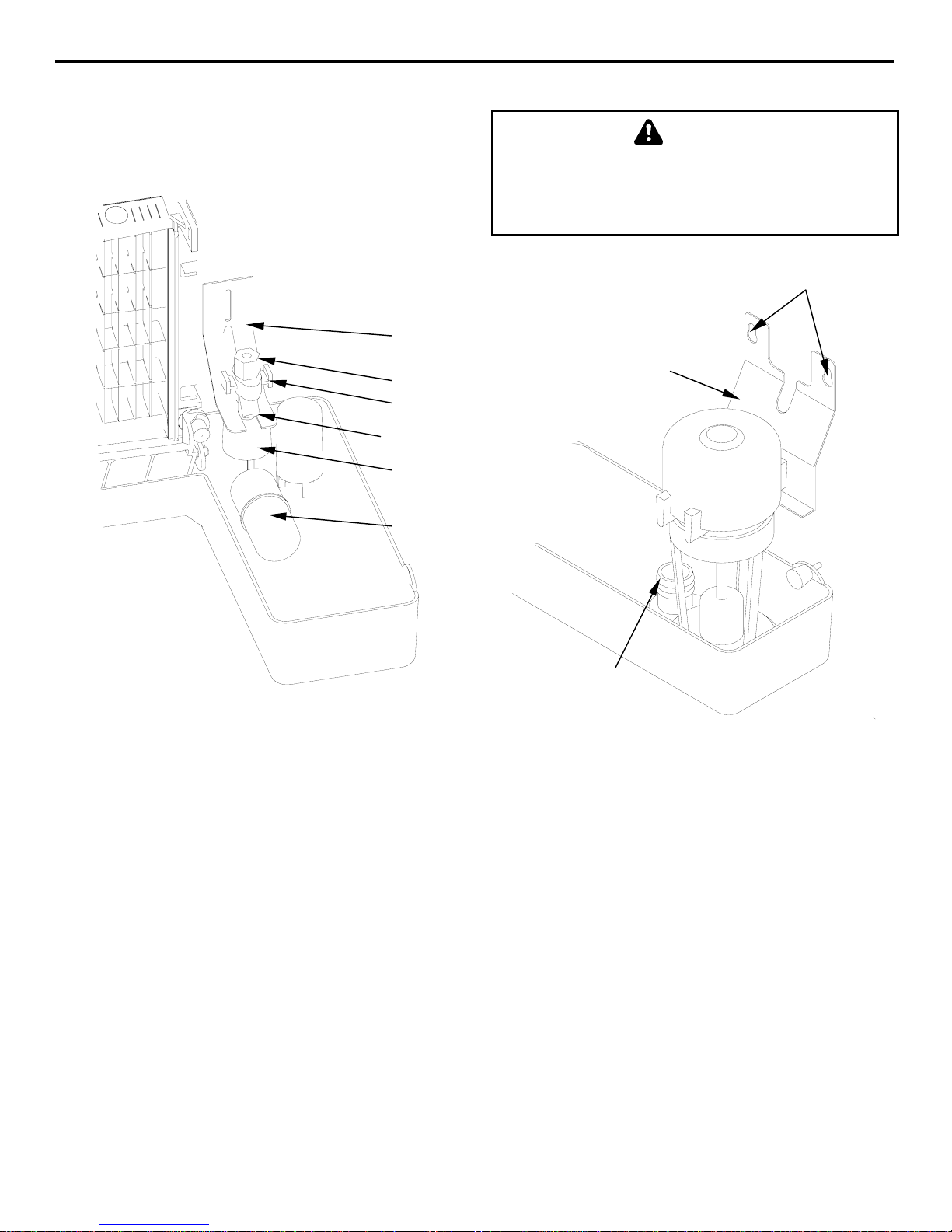
WATER PUMP REMOVAL
WARNING
Before removing any parts, unplug or disconnect
the electric power to the ice machine at the electric
service switch box, and turn off the water supply to
the ice machine.
SCREWS
FLOAT VALVE
BRACKET
COMPRESSION
FITTING
SHUT-OFF
VALVE
CA R P AND FILTE
SCREEN
SPLASH SHIELD
FLOAT
SV1695-2
Float Valve Removal
3. Pull the float valve forward and off the mounting
bracket.
4. Disconnect the water inlet tube from the float
valve at the compression fitting.
5. Remove the cap and filter screen for cleaning.
PUMP
MOUNTING
BRACKET
PUMP
OUTLET
SV1694-1
Water Pump Removal
1. Disconnect the water pump power cord.
2. Disconnect the hose from the pump outlet.
3. Loosen the screws securing the pump-mounting
bracket to the bulkhead.
4. Lift the pump and bracket assembly off the
mounting screws.
4-8
Page 28

Section 4 Maintenance
ICE DAMPER REMOVAL/INSTALLATION
Removal
1. Grasp ice damper and apply pressure toward the
left hand mounting bracket.
2. Apply pressure to the right hand mounting
bracket with thumb.
3. Pull ice damper forward when the right hand ice
damper pin disengages.
Installation
1. Place ice damper pin in left hand mounting
bracket and apply pressure toward the left hand
mounting bracket.
2. Apply pressure to the right hand mounting
bracket with thumb.
3. Push ice damper toward evaporator until right
hand damper pin engages.
STEP 1
STEP 2
STEP 3
STEP 2
SV1742A
STEP 1
STEP 3
SV1742H
4-9
Page 29

Maintenance Section 4
Removal from Service/Winterization
GENERAL
Special precautions must be taken if the ice machine
is to be removed from service for an extended period
of time or exposed to ambient temperatures of 0°C or
below.
CAUTION
If water is allowed to remain in the ice machine in
freezing temperatures, severe damage to some
components could result. Damage of this nature is
not covered by the warranty.
Follow the applicable procedure below.
SELF-CONTAINED AIR-COOLED
ICE MACHINES
1. Disconnect the electric power at the circuit
breaker or the electric service switch.
2. Turn off the water supply.
3. Remove the water from the water trough.
4. Disconnect and drain the incoming ice-making
water line at the rear of the ice machine.
5. Blow compressed air in both the incoming water
and the drain openings in the rear of the ice
machine until no more water comes out of the
inlet water lines or the drain.
6. Make sure water is not trapped in any of the
water lines, drain lines, distribution tubes, etc.
Pry Open the Water Regulating Valve
4-10
Page 30

Section 4 Maintenance
THIS PAGE INTENTIONALLY LEFT BLANK
4-11
Page 31

Maintenance Section 4
THIS PAGE INTENTIONALLY LEFT BLANK
4-12
Page 32

Page 33

 Loading...