

Manitowoc ECG080A, ECG018A, ECG023A, ECS031A,ECS031W, ECS018A Installation Use And Care Manual
...Page 1
Part Number 80-1651-3
Installation Use and Care
EC Series
Ice Machines
This manual is updated as new informati on an d models ar e rel eased. Visit our websit e for the latest man ua l.
www.manitowocice.com
05/10
Page 2

Table of Contents
Table of Contents
Section 1 - Installation Instructions
MODEL/SERIAL NUMBER LOCATION ............................................................................................... 1-1
LOCATION OF ICE MACHINE .............................................................................................................. 1-2
LEVELING THE ICE MACHINE ............................................................................................................ 1-2
ELECTRICAL SERVICE.......................................................................................................................... 1-3
WATER SERVICE/DRAINS ..................................................................................................................... 1-4
ICE MACHINE DIMENSIONS ................................................................................................................ 1-5
INSTALLATION CHECKLIST ................................................................................................................ 1-6
Section 2 – Component identification
EVAPORATOR COMPONENTS ............................................................................................................. 2-1
CONDENSER, CONTROLS, AND AIR FILTER .................................................................................... 2-2
Section 3 – Ice Making Sequence Of Operation
ICE MAKING SEQUENCE OF OPERATION ........................................................................................ 3-1
OPERATIONAL CHECKS ....................................................................................................................... 3-2
Section 4 – Maintenance
MAINTENANCE CHART ......................................................................................................................... 4-1
CLEANING CONDENSER ....................................................................................................................... 4-2
CLEANING PROCEDURE ....................................................................................................................... 4-3
SANITIZING PROCEDURE ..................................................................................................................... 4-4
REMOVAL FOR WINTERIZATION ...................................................................................................... 4-5
BEFORE CALLING FOR SERVICE ....................................................................................................... 4-6
Page 3
Installation Instructions
Section 1
Self-Contained
Air-Cooled
Self-Contained
Water-Cooled
Not Available
Not Available
ECS023A
ECS023W
ECG023A
ECG023W
ECS031A
ECS031W
ECG031A
ECG031W
ECS041A
ECS041W
ECG041A
ECG041W
ECS051W
ECG051A
ECG051W
ECS065A
ECS065W
ECG065A
ECG065W
ECS080A
ECS080W
ECG080A
ECG080W
from that of original manufactu r ed specifications.
installation procedures for yo u.
Ice Machine Model
Ice Cube Size
S - Standard Cube
Ice Machine Series
Condenser Type
A - Air - Cooled
General Information
It is recommen ded that this ice machine be inspect ed and
inst alled by a qual ified ser vi ce technician.
If you do not understand the procedures or the
safety precaut io ns that must be fo llow ed, call your
local service represent ative to perform the necessa ry
WARNING
Model Numbers
Th i s manual cove rs the follo wing mod e l s :
ECS018A
ECG018A
Follow all recommendations and instructions for proper
installation and safe operation of this ice machine.
WARNING
PERSONAL IN JU RY POTENTIA L
Do not operate equipment that has been misused,
abused, neglected, damaged, or altered/modified
ECS051A
Model Numbers Identification
EC S 018 A
G - Large Cube
W - Water- Cooled
1-1
Page 4
Installation Instructions
Section 1
Self-Contained
Air-Cooled
Self-Contained
Water-Cooled
Top/Sides
203 mm (8 in.)*
127 mm (5 in.)*
Back
127 mm (5 in.)*
127 mm (5 in.)*
he ice machine must be protected if it will be
Failure caused by exposure to freezing
THREAD
Location of Ice Machine
Leveling the Ice Machine
The loca tion selected for th e ice machine mu st meet the
follo wing crit er ia. If any of these crit er ia are not met, select
another location.
• The location m ust be indoor s.
• The location must be free of airborne and other
contaminants.
• The air temperature must be at least 10°C (50°F), but must
not ex ceed 4 3 °C (110°F).
• The location must not be near heat-generating equipment or
in direct sunl ight.
• The location m ust be ca pable of supp orting the weight of the
ice ma ch ine and a full bin of ice.
• The loca tion must al low enough cl earance for water, dra in
and el ectrical con nection s in th e rear of the ice machine.
• The location must no t obstruct airflow through or a roun d the
ice machine (condenser airflow is in and out the front). Refer
to the ch ar t below for cl earance r ecom mendations.
* NOTE: The ice machine may be built into a ca binet.
There is no minimum clearance requirement for the top or left
and ri ght sides of th e ice machin e. Th e listed valu es are
recomm ended for effi cient oper ation and s er vi cing only.
CAUTION
T
subjected to temperatures below 0°C (32°F).
temperatures is not covered by the warranty.
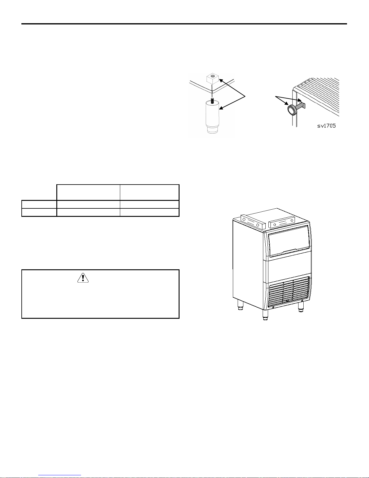
Leveler s a r e in clud ed wit h all i ce m ach in e. Legs a r e an available
option.
1. Screw the legs or levelers into the bottom of the ice
machine.
LEVELING LEG
INTO BASE OF
CABINET
2. Screw th e foot of each leg or level er in as far as possible.
Move the ice machine into its final position.
3. Level the ice machine correct ly. Use a level on top of the ice
machine. Turn each fo ot as necessary to level the ice
machine from front to
back and side to side.
1-2
Checking Ice Machin e Level
Page 5
Installation Instructions
Section 1
must conform to
local, stat e and national codes.
complete..
Air-Cooled
Water Cooled
Maximum
230/1/50
10 Amp
4.4
10 Amp
4.0
230/1/60
10 Amp
4.4
10 Amp
4.0
Electrical Servi ce
GENERAL
WARNING
All wiring and ground connections
VOLTAGE
The maximum allowable voltage variation is ± 6% of the rated
volta g e on the ice machine model/serial num ber plate at s tart-up
(when the electrical load is highest).
All ice m achines ar e factory pr e-wired with a 2 meter (6 ft)
power cord, no plug is supplied
FUSE/CIRCUIT BREAKER
A separ at e fu s e/ circuit break er m u st be pr ovi d ed f or each ice
machine. An electr ical di scon nect swit ch mu s t be provided if the
ice machine is hard wired (wired without a plug).
TOTAL CIRCUIT AMPACITY
The tot al circuit ampacity is u sed to help select the wir e si ze of
the electrical s u p p ly.
The wire size (or gauge) is also dependent upon location,
materials used, length of run, etc., This must be determined by a
quali fi ed electrician.
.
WARNING
Risk Of Electri cal Sho ck
This ice machine must be properly grounded and
connected to the field wiring ter minal in
accordance with all applicab le national and local
electrical codes by a qualif ied e lect r ician. Be fore
connecting wires, d isco nnect po wer at the electrical
disconnect and lock out to prevent accidentally
energizing.Con nect all electrical wiring before use do not energize ice mach ine until installation is
1. Connect –the three suppl y lead wir es (Blue, Brown,
and Yellow/Gr een) to t he field wiring terminal, “L”, “N”,
and “G”, the Yellow/Green wir e m ust c onnec t to the
“G”(ground).
2. After connecting the wiring to the terminal strip, the
supply lead must be secured to the cabinet with a
strain relief near the terminal strip.
3. Verify wiri ng is cont ained in the electrical wiring box.
Ice Machine
EC018
EC020
EC030
EC040
EC050
EC065
EC080
Voltage
Phase
Cycle
230/1/50 10 Amp 2.2 N/A N/A
230/1/60 10 Amp 2.2 N/A N/A
230/1/50 10 Amp 2.5 10 Amp 2.3
230/1/60 10 Amp 2.5 10 Amp 2.3
230/1/50 10 Amp 3.4 10 Amp 3.2
230/1/60 10 Amp 3.4 10 Amp 3.2
230/1/50 10 Amp 3.4 10 Amp 3.1
230/1/60
230/1/50 10 Amp 4.0 10 Amp 3.7
230/1/60 10 Amp 4.0 10 Amp 3.7
230/1/50 10 Amp 4.2 10 Amp 3.8
230/1/60 10 Amp 4.2 10 Amp 3.8
Maximum
Fuse/Circuit Breaker
10 Amp 3.4 10 Amp 3.1
Total Amps
Fuse/Circuit Breaker
Total Amps
1-3
Page 6
Installation Instructions
Section 1
Important
cooled condenser.
for water-c ooled condenser.
Water
Pressure
Ice Machine
Fitting
Tubing Size Up to Ice
Machine Fitting
**Drain Connection
18mm (3/4”) Minimum
0.6ºC (33ºF) Min.
32.2ºC (90ºF) Max.
140 kPa (20 Psi) Min.
3/8” Female pipe
15mm (1/2”) Inside
Condenser Water Outlet
1/2” Female pipe
15mm (1/2”) Minimum
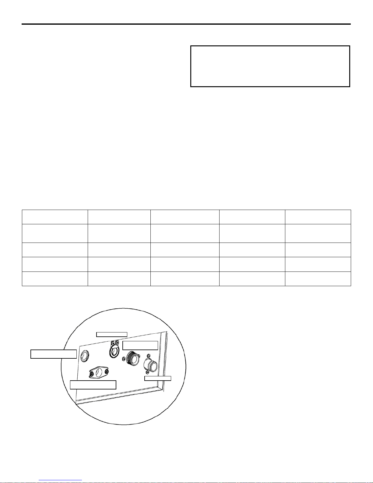
ELECTRICAL
DRAIN
POTABLE WATER
INLET
WATER COOLED
CONDENSER INLET
CONDENSER OUTLET
Water Service/Drains
WATER SUPPLY
Local wa ter cond itions may r eq uire treatment of the water to
inhibit scale formation, filter sediment, remove chlorine, and
impr ove t aste and clarity.
If you are installing a water filter system, make sure that
you use a separate line for waterFilt er life w ill be greatly reduced if filt ered water is u sed
WATER INLET LIN ES
Follow these guidelines to install water inlet lines:
• Do not connect th e ice machine to a hot water suppl y. Be
sure all ho t w ater restrictors install ed for other eq u ipment ar e
working. (Che c k valve s on sink fau c e ts, dishwa sher s, etc.)
• Water pressure t o the machine should be between 1.4 t o 5.5
bar (20 to 80 psi).
• If water pressure ex ceed s t he maximu m 5 bar recommended
press ure, obtain a water pressure re gula tor fr om your
Manitowoc distri butor. Adjust pressur e to 2.5 bar (37 psi).
• Install a wate r shut-off va l ve.
• Connect to a pot able water s upply only.
DRAIN CONNECTIONS
Follow t hese guidelines when installing dra in lines to pr event
drain water from flowing back into the ice machine and storage
bin:
• Dra i n line s must have a 3.8 cm (1 .5 in ch) drop of run for
each meter (3 feet), and must not create traps.
• The floor drain must be lar ge enou gh to ac c ommodate
drainage from all drains.
• Run sep ar ate bin and water-cooled condens er drain lines.
Insulate them to prevent condens ation
WATER SUPPLY AND DRAIN LINE SIZING/CONNECTIONS
.
Water Temperat ure
*Ice Making
Water Inlet
Outlet
Condenser Water Inlet
10ºC (50ºF) Min.
32ºC (90ºF) Max.
-----
----- -----
WATER COOLED
140 kPa (20 Psi) Min.
550 kPa (80 Psi) Max
1030 kPa (150 Psi) Max
3/4” Male Pip e
Thread
----- 7/8” Barb connection
Thread
Thread
* Water inle t hose supplie d with machine.
3/4” Female Pip e Thread/ 2 meters long.
** Drain hose supplied with mach ine.
7/8” (22.2mm) hose/ 2 meters long.
15mm (1/2”) Inside
Diameter Minimum
Inside Diameter
Diameter Minimum
Inside Diameter
1-4
Page 7
Installation Instructions
Section 1
MODEL
H W D 1 6 2 7 4 9 5 10 3 8
MM
635
343
420
NA
NA
NA
NA
63.5
88.9
50.8
140
76.2
38.1
INCH
25.0
13.5
16.5
NA
NA
NA
NA
2.5
3.5
2.0
5.5
3.0
1.5
EC020
EC030
MM
650
450
475
100.5
53.4
45.5
138.4
125.5
118.4
45.3
225
125.5
183.4
EC040
EC050
MM
800
550
550
108
77.5
68
123
87.5
221
68
275
108
168
EC065
EC080
MM
902
700
600
114.3
82.6
76.2
120.7
95.25
222.25
82.6
279.4
120.7
171.5
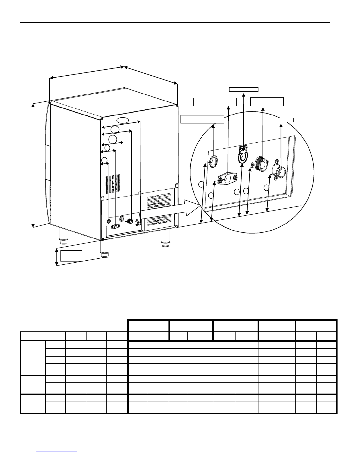
D
W
H
1 2 4
5 3 6
7 8 9
10
152.4 mm
(6in.)
ELECTRICAL
DRAIN
POTABLE WATER
INLET
WATER COOLED
CONDENSER INLET
WATER COOLED
CONDENSER OUTLET
Dimensions
EC018
Condenser Water
Inlet
Condenser Water
Outlet
Potable Water Inlet Drain Electrical
&
&
&
INCH
INCH
INCH
25.59 17.72 18.7 3.96 2.1 1.79 5.45 4.94 4.66 1.78 8.86 4.94 7.22
31.5 21.65 21.65 4.25 3.05 2.68 4.82 3.44 8.71 2.68 10.83 4.25 6.59
35.5 27.5 23.5 4.5 3.25 3.0 4.75 3.75 8.75 3.25 11.0 4.75 6.75
1-5
Page 8
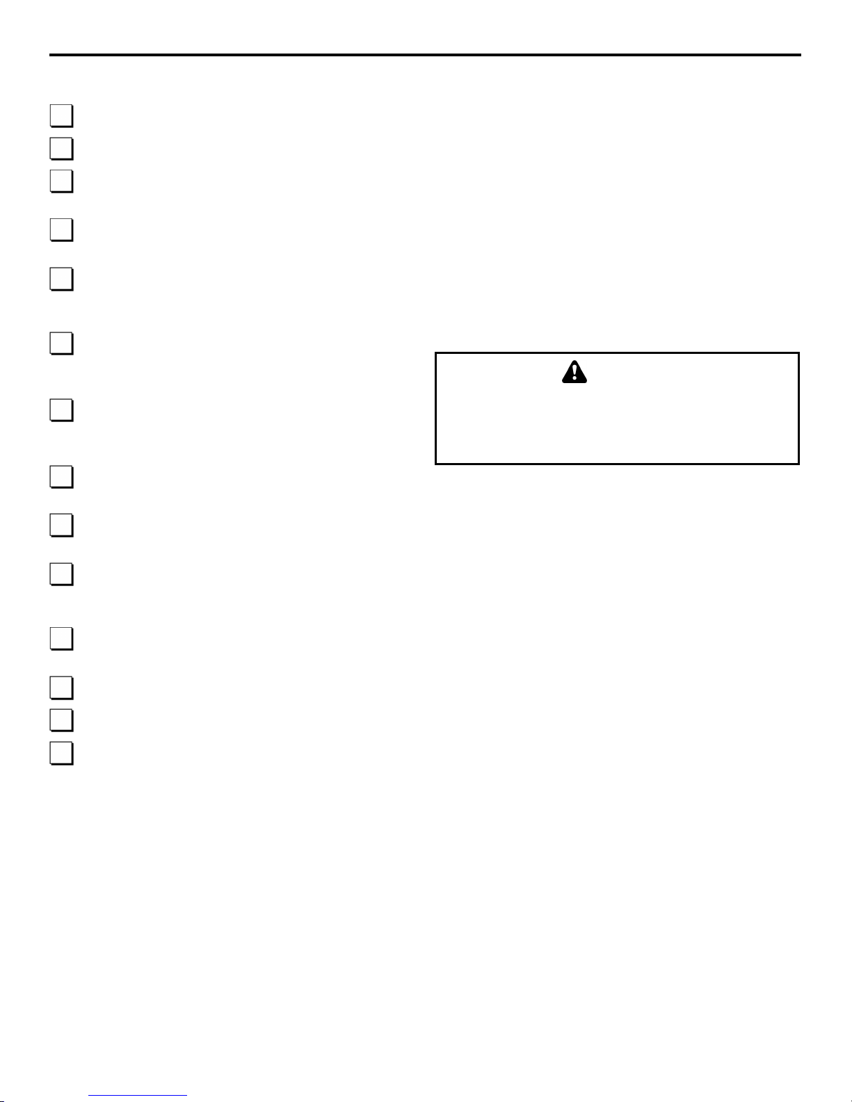
Installation Instructions
Section 1
Is the ice machin e level ?
Has all of the internal packing been removed?
Have all of t he electr ical and water con nections been
Has th e s upply voltag e been tested and checked ag ainst
Are all components installed as shown in Section 3?
Has th e ice machine been instal l ed where ambi en t
Has th e ice machine been instal l ed where the incoming
Is ther e a s ep ar ate drain line for the wat er-cooled
Are al l el ectrica l l eads free from con tact with
Has th e own er/operator been instructed r eg arding
Has th e own er/operator completed the warr anty
Has th e ice machine an d bin been sanitized?
Has thi s man u al been given to the owner/operat or?
Is the ice -off - wash switch set to the ice position?
from that of original manufactu r ed specifications.
Installation Checklist
Before Starting the Ice Machine
made?
the rating on the nameplate?
Water s pray bar, ice chute, wat er curtain and su mp drain
overflo w t u b e are all in pl a ce?
temperatures will remain in the range of 10° - 43°C
(50° - 110°F)?
water t emperature wi ll remain in the range of 10° - 32°C
(50° - 90°F)?
condenser?
All ice m achines ar e factory-operated and ad ju s ted before
shipment. Normally, new installations do not require any
adjustment.
To ensure proper operation, follow th e Operational Checks in
section 3 of thi s manual. Starting the ice machine and completin g
the Oper ational Checks are th e responsibilities of the
owner/operator.
Adjustments and maintenance
procedures outlined i n this manual
are not covered by the warranty.
WARNING
PERSONAL INJURY POTENTIAL
Do not op erat e equ ipment that has be en misu se d,
abused, neglected, damaged, or altered/modified
refrige r ation lines a nd mo ving equipment?
maintenance an d the use of Manit owo c Cleaner an d
Sanitizer?
regi s tr ation car d ?
1-6
Page 9

Section 2
Component Identification & Removal
AIR COOLED
CONDENSER
ON/OFF/WASH
TOGGLE SWITCH
TOGGLE SWITCH
Component Identification
WATER CURTAIN
WATER SUMP TROUGH
TIMER MECHANISM
ICE CHUTE
EVAPORATOR
SPRAY BAR
SPRAY NOZZLES
2-1
Page 10

Component Identification & Removal
Section 2
REMOVE TWO SCREWS – SLIDE
ALIGN DOOR PINS WITH TRACK SLOTS , THEN LIFT
DOOR OUT OF TRACK
Top Cover
For easiest access t o t he evapor ator compartment, th e top cover
can be r em oved.
1. Remove tw o screws on the rear of the ice machine.
2. Slid e t op cover back to disengag e th e three pins fr om th e
front panel.
COVER BACK TO REMOVE
Bin Door
Allows access to the storage bin.
1. Remove top co v er.
2. Slide door up until rear pins align with slot in door tracks.
3. Lift rear door pins out and slide door up un til fr ont door
pins align with s lot
4. Lift door out of door track.
2-2
Page 11

Section 2
Component Identification & Removal
ICE CHUTE
Water Curtain
The ice curtain is des igned t o keep th e s praying water from
escaping the evapor ator c ompartment. Removal of the bin door
is not r eq uired, but enhances a cces s.
1. Grasp one end of the ice curtain an d li ft up.
2. Pivot water curt ain and disen ga g e r emaining end.
3. To re-install int o ice ma chine , gras p one en d of the water
curtain, install one end, pivot the opposite end and pull
down int o position. Make sure ta bs a re sec ure in grooves.
Ice Chute
The ice ch ute is positioned over the spray noz z les and allows the
ice to easily fall into the bin. It must be firmly positioned on the
Water Distribution Assembly, with the front edge inside the
water trough or t he spr ay noz z les will not be aligned wi t h the
spray holes, and spray water will fall into bin.
1. Gra b protruding spray hol es on on e end and lift up.
2. Pivot ice chute and remove.
3. To re-install ice chute, gr asp protr uding s pray holes a nd
position over Water Distribution Assembly. Make sure rear
supports are ove r Water Di s t ribution Assem bly, and fr ont
edge is inside of water trough.
WATER CURTAIN
2-3
Page 12

Component Identification & Removal
Section 2
OVERFLOW TUBE
Spray Bar
The spray bar supplies water to the individual ice-making cups.
Water from the Water P um p s prays through the nozzl es , located
on the upper portion of the tubes.
Sump Drain Overfl ow Tube
The sump drain overflow tube is located in the evapor ator water
sump.
1. Remove shutters and ice chute.
1. Gra s p one end of the spray bar , lift u p and remove fr om
se a t formed in w ater trough.
2. Remove bot h plastic c lips on water i nlet tubin g by graspin g
both ears on clip and sep arating
3. Apply food grade lubricate to ease re-assembly of spray bar
components when necessary.
4. To re-install spray bar, position water inlet tubing on inlet
por ts, an d squeeze clips until tight.
5. Reposition assembly on water trough seat.
Nozzl es and inser ts can be removed for clean ing by unscrewing
nozzles. Inserts are located inside the spray bar ports. The spray
bar also d isass e mbles for easy cleaning.
2. Lift spr ay bar or dis con nect and rem ove for easiest access.
3. Pul l up on over flow tube to re move.
4. To replace plug, insert in hole, and push with force to make
a tight sea l.
2-4
Page 13

Section 2
Component Identification & Removal
Door Frame
It is not n eces sary to remove the door frame to clea n the ice
machine.
1. Remove top cover and bi n door .
2. Remove two screws (1 on each side of door track).
3. Lift door track out of i c e machine.
REMOVE 2 SCREWS
2-5
Page 14

Section 2
Component Identification & Removal
PAGE INTENTIONALLY LEFT BLANK
2-6
Page 15

Section 3
Ice Machine Operation
Prior to start up of this machine, a thorough
cleaning and sanitization should be performed.
t h is m a n u al.
Ice Machine Operation
Ice Making Sequence of Operation
Important
Follow instructions in the maintenance section of
Initial Start-Up
1. Water Inlet
Turn the toggle switch to wash/fill,the water fill valve and pump
are en ergized, wait for 90 seconds, th en turn the switch to off
position.The water inlet valve on thi s machine energ i zes i n the
harvest cycle, therefore pr i ming the system with water will allow
the system to start up next cycle with a full reservoir of water.
2. Freez e Cyc le
Turn the on/off/wash switch t o on. Th e compre s sor, and wate r
pump wil l start, thu s s tarting th e fr eezing cycle. The pump spr ays
water in to the inverted cups. The water freez es layer by layer,
until an ice cube forms in each cup.
At th e same time the comp ressor star ts, the condenser fan motor
(air-cooled models) is supplied with power throughout th e freeze
and harvest cycles. The freeze cycle continues and t he eva porator
therm ostat reach es the adjust ed s et point.
• EC18/20
A harvest cycle starts.
3. Harvest Cycle
The compressor con tinues to operate an d the water pump is deenergized. The hot gas val ve e nergiz es, allowin g hot gas to ent e r
and warm th e eva porat or .. The water va lve is also ener gized,
aiding with harvest, as well as filling up the sump with fresh
water for a new freeze cycl e.
The ice fa lls from th e cu p s an d i s directed into the bin by the ice
chut e. Th e h arvest cycle c ontinues until:
• EC18/20
The evaporator thermostat changes position.
• EC30/40/50/65/80
The timer reaches the factory setting of 3 minutes.
The hot ga s valve, and water va lve de-energi ze. If ice cubes are
not contacting th e bin thermostat a new freez e cycle is initiated
as the water pump energizes and sprays water into the cups,.
4. Automatic Shut-Off
When th e storage bin is full, the ice will come in contact with the
bin thermostat which is located inside the bin. The machine will
stop after approximately one minute of continuous ice contact
with the bi n thermostat probe.
The ice machine remains off until enough ice has been removed
from the storage bin to allow the ice to fall clear of the bin
therm ostat probe. A s the ice cl ears the probe, the bin ther mostat
warm s up an d the machine starts another freeze cycle.
• EC30/40/50/65/80
The thermostat energizes the tim e d elay relay. When the timer
reach es setpoint (1 0 min u tes factor y setting) th e harvest cycle is
initiated.
3-1
Page 16

Ice Machine Operation
Section 3
Important
It is recommended that adjustments made to this ice machine
seriously affect the life of this ice machine.
40
38
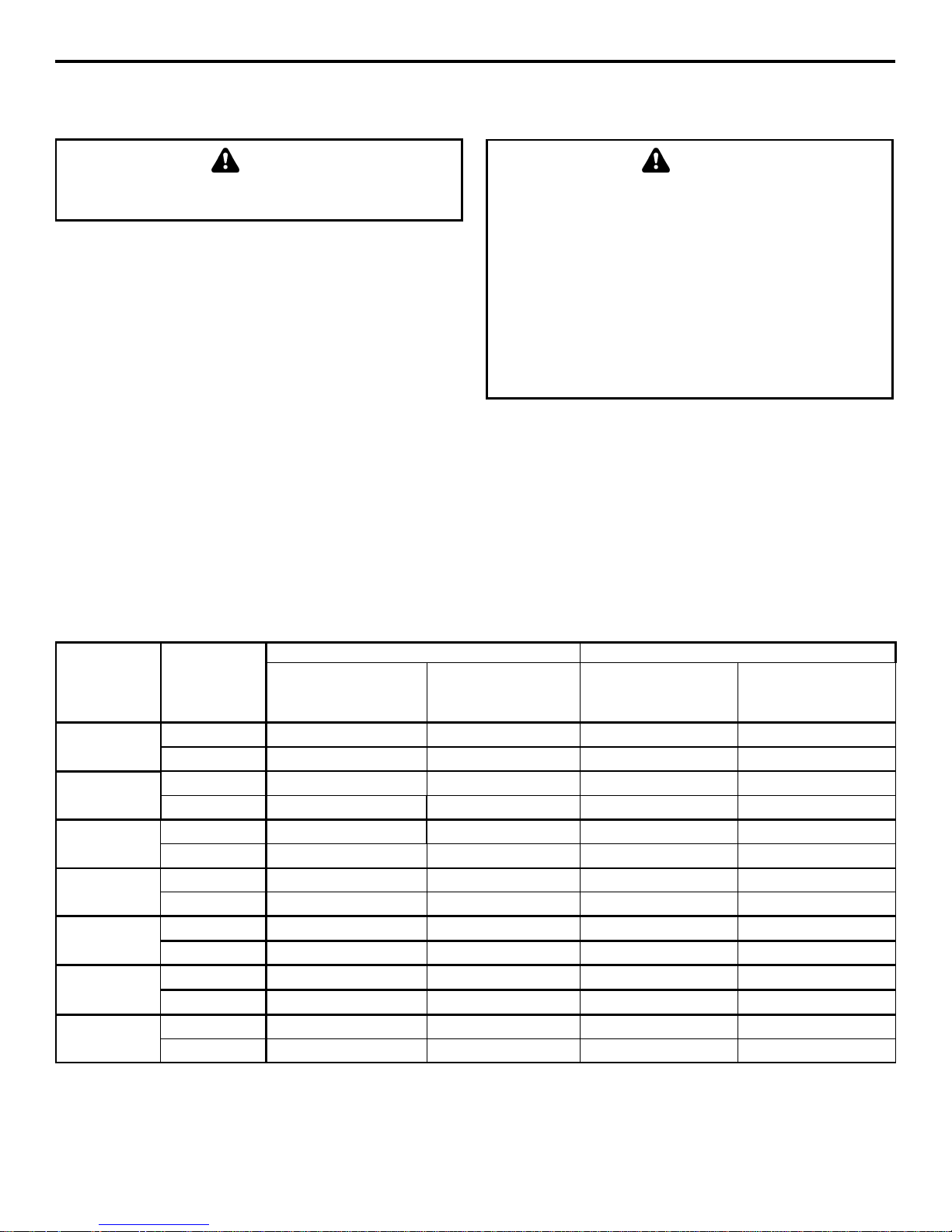
Large cube 32g
Dimple
33
34
Fig. 6
Operational Checks
GENERAL
Your i ce machine was fa ctory-operated an d ad ju s ted before
shipment. Normally, a newly installed ice machine does not
require any adjustment.
To ensure proper operation, always follow these Operational
Check s when starting the ice ma ch ine:
• for the first time
• afte r a prolonged out of service period
• after cleaning and s an itizing
Routine adjustments and maintenance procedures outlined in this
manua l are not cover ed b y the warranty.
be made by a qualified technician. Improper adjustment, may
CUBE SHAPE
The standard cu be has an average wei g ht of 19 grams, while th e large cube ha s an average wei ght of 32 gram s .
Notice t he normal d im ple in the center of the cube.
ICE CUBE THICKNESS CHECK
The ice cu be t hickness is factor y-set to maint ain the ice cube
thickness at the proper size and weight.
1. Allow the ice machine to operate for thr ee com p lete cycles.
The cubes should ha ve a s ma ll dimple in th e cen ter
2. Cycle ti mes vary, according to su r roundin g air and water
inlet temperat ures.
3. If cubes are n ot full (large dimple), turn evaporator
thermostat o ne increme nt towards t he right t o inc rease c ube
size. Allow ice machine to complet e th ree cycles. C heck
cube
4. If cubes are too full, ( no dimple), turn evaporator thermostat
one in cr ement towar d s th e left to decrease cube si z e. Allow
ice ma ch ine to operat e th ree compl ete cycles.
Standard cube 19g
3-2
Page 17

Section 4
Maintenance
Semi
Clean cabinet ext er ior
X X X Sanitize Ice Bin
X X X Clean Evaporator
X S S Sanitize Evaporator
X S S
S
Check I ce Quality
X S S
S
local service representative to perform the
Section 4
Maintenance
General
The end u ser is respon sible for main taining the ice machin e in
accord ance with the instructions in this manual.
procedu res are not covered by the warrant y.
If you do not understand the procedures or the
safety precaut ions that must be fo llowed, ca ll your
necessary maintenance procedures for you.
WARNING
Maintenance Weekly Monthly
Maintenance
Basic hygiene and maintenance of your I ce Mach ine, will
increase its reliability, increase performance, and help save on
water an d power consu mp tion. Ice pr od u ction will be m aintain ed
within the manufacturers guidelines, and unwanted repairs due to
maintenance issues will be minimized.
The char t below is an overvi ew of the maintenance that the en d
user an d service tech nician sh ould perfor m, and the fr equency.
These figures are the minimum required. If the Ice Machine is
supplied with hard water, more frequent evaporator cleaning
should be performed. If the condenser air filter is totally blocked,
after on e week, more frequent cl eaning is recom mended.
Annual
Annual
After pr olonged
shutdown
At Start-up
Clean Condenser Coil X S S
X = End User
S = Service Com p any
4-1
Page 18

Maintenance
Section 4
tch before performing
The condenser fins are sharp. Use care when
cleaning them.
FIN COMB
CONDENSER
Cleaning the Conden ser
WARNING
Disconnect e lectric power to the ice machine at the
electric service swi
maintenance on equipment.
AIR-COOLED CONDENSER
A dirty condenser r es tr icts air fl ow, resulting in excessi v ely high
operating temperatures. This reduces ice production and shortens
component life.
Clean th e condenser at least every six months.
1. Remove Plastic Front Grill removing two Phillips head
screws. C lean Grill opening s before repl a cing.
2. Clean the outside of the condenser with a soft brush or a
vacuum with a brush attachment. Clean from top to bottom,
not sid e to side. Be car eful not to bend the condenser fins.
WARNING
“COMB”
DOWN
ONLY
3. Shine a flashlight through the condenser to check for dirt
between the fins. If dirt remains:
A. Blow compr essed air through the condenser fins. Be
careful not to bend the fan blades.
B. If dirt or grease remains between fins, consult your
service representati ve.
4. Straighten any bent condenser fins with a fin comb.
WATER-COOLED CONDENSER
AND WATER REGULATING VALVE
The water-cooled con d enser and wa ter-regulating valve may
require cleaning due to scale build-up.
Low ice production, high water consumption and high oper ating
temperatures and pressures all may be symptoms of restrictions
in the condenser water circu i t.
Because the clean ing procedures requ ire special pumps and
cleaning solu ti ons, quali fi ed mainten ance or ser vi ce p ersonnel
must perform them.
4-2
Page 19

Section 4
Maintenance
d Ice Machine Cleaner and
and Sanitizer solut ions together
hine Cleaner or
Cleaner
Water
500 ml (16 oz)
4 l (1 gal)
Never use anything to force ice from the
Interior Cleaning and Sanitizing
CLEANING PROCEDURE
GENERAL
Clean and sanitiz e the ice machine every six m on ths for effic ient
opera tion. If th e ice machine r eq u ires more freq u ent cleaning and
sani ti zing, con su lt a qualifi ed s ervice company to test the water
quality and recommend appropriate water treatment.
If requ ired, an extremely dirty ice machine may be tak en apart
for cl ean ing and sani tizing.
CAUTION
Use only approve
Sanitizer. Read and u nderstand all labels printed o n
bottles before use. Do not mix Ice Machine Clean er
WARNING
Wear rubber glo ves and safety goggles (and/o r face
shield) when handling Ice Mac
Sanitizer.
Ice mach ine cleaner is used to remove lime scale or other mineral
deposits. It is not used to remove algae or slime. Refer to
“San itizing Pr ocedure” on the next page for r emoval of alg ae and
slime.
Mix 4 liters of water with 500 ml of cleaner in a plastic or
stain l es s container .
Step 1 Set the toggle switch to the OFF position at the end of a
Harvest Cycle, aft er ice releases from the evapora tor. Or, set th e
switch to the OFF position and allow the ice to melt off the
evaporator.
CAUTION
evaporator. Damage may resu lt.
Step 2 Remove all ice from the bin.
WARNING
Disconnect e lectric power to the ice machine at the
electric switch box before p roc eeding .
Step 3 Remove al l parts as described in S ection 3, Component
Identification & Removal.
4-3
Page 20

Maintenance
Section 4
Sanitizer
Water
60 ml (1 oz)
12 l (3 gal)
Never use anything to force ice from the
Step 4 Take all components to sink and with 2 liters
Clean er/Water mixture clean all comp onents with a soft n yl o n
brush. Disassem ble spray bar, remove nozzles and inserts and
soak for 5 minutes. For heavily scaled parts, soak in solution for
15–20 minutes. Rinse all components with clean water.
Step 5 While components are soaking, use nylon brush to scrub
insi d e of ice bi n. Scrub inside of door, door track, bin, sump
trough, and evaporator moldings. With clean water, rinse all of
these areas thoroughly.
Step 6 Replace s ump overflow tube and pour r e maining 2 lit ers
of mixture into the water sump. Replace all parts.
Step 7 Disconnect the incom i ng ice -making wat er line.
Step 8 To start a cleanin g cycl e, set th e tog g le switch t o the
WASH position.
Step 9 After 10 minutes, set the toggle switch to the OFF
position. Remove water cur tain, ice ch ut e and over flow t u be
from the water sump. Allow all water to drai n from the sump.
Replace drain plug and fill sump with 2 liters of water. Set toggle
switch to Wash and circulate for 10 minutes.
Step 10 After 10 minutes, set toggle switch to off position.
Remove wat er curta in , ice chute, water sump over flow tube.
Drain water from sump and replace tube.
Mix 4 liters of water with 30 ml of sanitizer in a plastic or
stain l es s container .
Step 11 Set the toggle switch to the OFF position at the end of a
harvest cycle, a fter ice rel eases from th e eva p orator. Or, set the
switch to the OFF position and allow the ice to melt off the
evaporator.
CAUTION
evaporator. Damage may resu lt.
Step 12 Remo ve a ll ice from th e bin.
Step 13 Remove Water Curtain and Ice Chute as described in
Section 3, Component Identification & Removal.
4-4
Page 21

Section 4
Maintenance
Step 14 Take all components to sink and with 2 liters
Sanitizer/Water mixture clean all components with a soft nylon
brush. Rinse all Components with clean water .
Step 15 Use brush to scrub ins ide of i c e bin. S crub inside of
door, door track, bin, water sump, water distribution assembly
and eva p orator moldings. With clean water , r inse all of thes e
areas thoroughly.
Step 18 After 10 minutes, set the toggle switch to the OFF
position. Remove water curtain an d ice chute Rem ove ov er flow
tube from water sump. Allow all water to drain from sump.
Replace over flow tube and fill sump with 2 liters of water. Set
toggle switch to Wash and allow circulation for 10 minutes.
Step 19 Repla ce a ll parts. Connect the incoming i ce-making
water line.
Step 16 Replace s ump drain ove r flow tube, and transfer
remaining 2 liters of solution to the sump trough. Replace all
components.
Step 17 To start a sanitizing cycle, set the tog g le switch to the
WASH position.
Step 20 Place t ogg le switch in WASH/FILL f or 90 seconds and
then to ICE position, ice machine will go into ice making cycle.
4-5
Page 22

Section 4
Maintenance
temperatures, severe damage to some
Exterior Cleaning
Clean the area around the ice machine as often as necessary to
maintain cleanliness and efficien t operat ion.
Spong e any dust and dir t off the out side of the ice machine with
mild soap and water. Wipe dry with a clean, soft cloth.
A commercial gra d e st ainless steel cleaner and poli sh may be
used.
Removal f rom Service/ W interization
GENERAL
Specia l precautions must be t aken if the ice machine i s t o be
removed from ser vi ce f or an exten d ed p er iod of time or exposed
to ambient temperatures of 32°F (0°C) or be low.
CAUTION
If water is allowed to remain in the ice machine in
freezing
components cou ld resu lt. Da mage of this nature is
not covered by the warranty.
Follow the appli cable procedure below.
WATER-COOLED ICE MACHINES
1. Perform steps 1-6 under “Air-Cooled Ice Machines.”
2. Disconnect the incoming water and drain lines from the
water-cooled cond enser.
3. Insert a large screwdriver between the bottom spring coils of
the wat er r eg u lating val ve. P ry upward t o open the valve.
AIR-COOLED ICE MACHINES
1. Disconnect the electric p ower at the circu it breaker or the
electric ser vi ce s witch.
2. Turn off the water supply.
3. Drain the water from the water sump and water pump by
disconnecting th e water pump tubing.
4. Disconnect and drain the incoming ice-m aking water line
and disconnect the tubing from the water inlet valve outlet
and allow water to drain.
5. Blow compressed air in the drain opening and water valve
ou t let ho se, then rea t tac h.
6. Make sure water is not trapped in any of the water or drain
lines.
Pry Open the Water Regulating Valve
4. Hold t he valve open and blow compressed air through the
condenser unti l wa ter no longer exits.
SV1624
4-6
Page 23

Section 4
Maintenance
Problem
Cause
Correction
Ice Machine Will Not Run
Toggle switch is not in ice position
Place toggle switch in ice position
No Power – Breaker off, fuse blown,
unplugged
Restore power
Bin Thermostat incor r ectly adjusted
Adjust bin thermostat
Ice machine runs and no ice is
No water to ice machine
Correct water supply
Water sump overflow tube out of
Re pos itio n/ inst al l overf low tube
Evaporator thermostat incorrectly
adjusted or faulty
Adjust or replace evaporator
thermostat
Freeze cycle long – low
Dirty condenser
Clean condenser
Water temperature too high
Connect to a cold water supp ly,
other equipment work properly
Refrigeration problem
Call for se rvice
Freeze Cyc l e
Shallow, incomplete or white
Ice machine is dirt y
Clean & sanitize the ice machine
Water pressure supp ly incorr ect
Verify water pressure is co r r ect
Air temperature around ice machine is
too high
Vent area or move ice machine
Evaporator thermostat incorrectly
adjusted
Adjust evaporator thermostat
Harvest Cycle
Will not initiate a harvest cycle
Evaporator thermostat incorrectly
Adjust or replace evapor ato r
Timer Problem
Call for se rvice
Ice cubes do not release
Ice machine is dirt y
Clean and sanitize the ice mach ine
Low ambient around ice machine
Adjus t t imer or move ice machine
Evaporator thermostat incorrectly
Adjust evaporator thermostat
Before Calling for Service
If a problem arises during oper ation of your ice machine, follow the chart below before ca lling for serv ice.
Routine adjust ments and maintenance procedures are not co vered by the warranty.
produced
position
production
verify check valves in faucet s and
ice cubes
adjusted or faulty
adjusted (cubes too large)
thermostat
to warmer area
4-7
Page 24

Section 4
Maintenance
4-8
Page 25

Owner Warranty Registration Card
Important
Complete and mail the OWNER WARRANTY
GENERAL
The packet containing this manua l also includes
warranty information. Warranty coverage begins the
day you r new ice mac h in e is ins t a lle d.
REGISTRATION CARD as soon as possible to
validate the installation date.
If you do not return your OWNER WARRANTY
REGISTRATION CARD, the date of sale to the
Manitowoc Distributor will be used as the first day of
warranty coverage for your new ice machine.
Warranty Coverage
GENERAL
The follow ing Warranty outline is provided for your
convenience. For a det ailed explanation, read the
warranty bond shipped with each product.
Contact your local Manitowoc representative or
Manitowo c Ice if you need further war r ant y
information.
PARTS
1. Manitowo c warrant s t he ice machine against
defects in materials and wor kmanship, under
norma l us e and service for two (2) years fro m the
date of original installation.
LABOR
1. Labor required to rep air or replace de fective
components is covered for one (1) year from the
date of original installation.
AUTHORIZED WARRANTY SERVICE
To comply with th e prov isions of the warrant y, a
refrigerat ion service co mpa n y qualif ied and
authorized by your distributor must perform the
warranty repair.
EXCLUSIONS
The following ite ms are not included in the ice
machine’s warranty coverage:
1. Normal maintenance, adjustments and cleaning.
2. Repairs due to unautho r ized modifications to the
ice machine or use of non-standard parts without
prior wr itten app roval from t he manufacturer.
3. Damage caused by improp er insta llation of the ice
machine, electrical supply, water supply or
drainage, or damage caused b y floo ds, sto r ms, or
other acts of God..
4. Parts or assemblies subjected to misuse, abuse,
neglect or accidents.
5. Damage or problems caused by inst allation,
cleaning and/or maintenance procedures
inconsistent with the t ech nica l instr uctions
provided in this manual.
6. Premium labor rate s due to holidays, overtime,
etc.; travel time; flat rate service call charges;
mileage and miscellaneo us to ols and material
char ges not lis ted on the payment s chedule.
Additional labor charges resulting from the
inaccessibility o f equip me nt ar e also excluded
SERVICE CALLS
Normal maintenance, adjustments and cleaning as
outlined in this manual are not covered by the
warranty. If you have followed the procedures listed
on the “Before Calling For Service” chart in this
manual, and the ice machine st ill does no t p er form
properly, call your author ized service company.
NOTE: If the dealer you purchased the ice machine
from is not author ized to per for m warranty service,
contact your distributor for the name of the nearest
authorized service repr esentative.
Page 26

We reserve the right to make product improvements at any time.
MANITOWOC ICE
EC DECLARATION OF CONFORMITY
05
Specification s and design are subject to change without noti c e.
We hereb y declare th at our product s , ice machines and Mult iplex refrigerat ion equipm en t com ply with all the essent ial
requirements of the listed EC- directives.
Manufacturer: European Distribu tor:
Mani towoc Ice, Inc. _____________________________________________
2110 South 26
Manitowoc Wisconsin 5421-1720 _____________________________________________
Representati ve Of Manitowoc Ice, Inc: Repres e ntative o f European D istribut or:
Randy Haack, Engineering Manager ______________________________________________
th
Street _____________________________________________
______________________________________________
Model and Serial No. Applied EC Di rectives:
Low Voltage 73/23/EEC
EMC 89/336/EEC
Pressure Equipment 97/23/EC
Applied Standards
EN60335-1 Safet y of hou se hold and si m ilar elect ri c al ap pl iances EN55014 Electrical Mot o r Operated A p pl i an ces (Emis sions)
EN60335-2-24 Part icul a r re quirem ents re frige r ators, fo od freez ers and i ce makers EN55104 Electro magnetic compatibility (Immunity)
EN378-1 to –4 Refrigeration plants
8201043
Website - www.manitowocice.com
2010 Manitowoc Ice
 Loading...