

Page 1
OPERATOR MANUAL
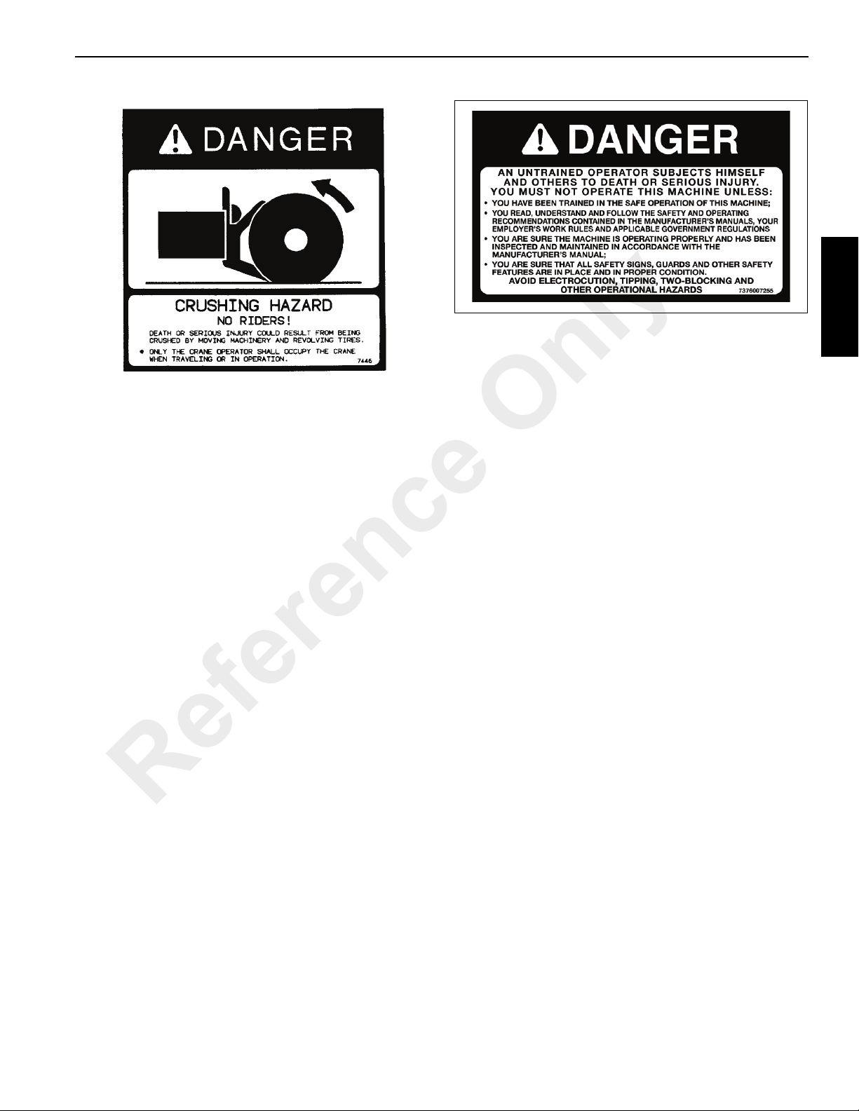
An untrained operator subjects himself and others to death or
serious injury. Do not operate this crane unless:
• You are trained in the safe operation of this crane. Manitowoc is not
responsible for qualifying personnel.
• You read, understand, and follow the safety and operating
recommendations contained in the crane manufacturer’s manuals and
load charts, your employer’s work rules, and applicable government
regulations.
• Y ou are sure that all safety signs, guards, and other safety features are
in place and in proper condition.
• The Operator Manual and Load Chart are in the holder provided on
crane.
DANGER
!
Supplement
Crane Warm-up Procedures
Reference Only
© 2015 Manitowoc
Published 3-10-2015, Control # 571-00
Page 2

SECTION CONTENTS
Crane Warm-up Procedures. . . . . . . . . . . . . . . . . . . . . . . . . . . . . . . . . . . . . . . . . . . 1
Engine. . . . . . . . . . . . . . . . . . . . . . . . . . . . . . . . . . . . . . . . . . . . . . . . . . . . . . . . . . 1
Transmission . . . . . . . . . . . . . . . . . . . . . . . . . . . . . . . . . . . . . . . . . . . . . . . . . . . . 1
Hoist . . . . . . . . . . . . . . . . . . . . . . . . . . . . . . . . . . . . . . . . . . . . . . . . . . . . . . . . . . . 1
Swing Drive and Turntable Bearing . . . . . . . . . . . . . . . . . . . . . . . . . . . . . . . . . . . 1
Axles. . . . . . . . . . . . . . . . . . . . . . . . . . . . . . . . . . . . . . . . . . . . . . . . . . . . . . . . . . . 2
Hydraulic Oil System . . . . . . . . . . . . . . . . . . . . . . . . . . . . . . . . . . . . . . . . . . . . . . 2
Reference Only
Page 3

This Supplement provides information regarding the proper
warm-up procedures for operating the crane in colder
temperatures. The information pro vided her e sup plements
the Operator and Service Manuals and must b e used in
conjunction with these manuals.
CRANE WARM-UP PROCEDURES
The following procedures detail the actions that must be
taken to properly warm the different crane components
before operating the crane.
NOTE: For temperatures below -9°C (15°F) refer to arctic
lubricants and conditions in th e Operator and
Service Manuals.
Before starting the crane, ensure the appropriate lubricants
are used to provide lubrica tion for th e prevailing ambient
temperatures in which the crane will operate in (a list of
lubricants and their temperature ranges can be found in the
Lubrication section of your crane’s Operator Manual, by
contacting your local Manitowoc distributor, or by contacting
Manitowoc Crane Care directly).
Operating the transmission with a sump temperature below
normal operating temperature is limited to:
• operating in the neutral gear or
• driving with an unloaded crane while not exceeding
1500 engine RPM and not exceeding half throttle.
Alternate Warm-up Procedures for Tr uck Mount (TM/
TMS) Cranes:
1. Setup the crane on outriggers.
2. Engage the transmission and allow crane to run at idle
until the temperature of the transmission sump reaches
normal operating temperature.
Hoist
Performing a warm-up procedure is recommended at every
startup and is required at ambient temperatures below 4°C
(40°F).
Warm-up Procedures:
1. Without operating the hoist function, warm the hydraulic
oil (see Hydraulic Oil System, page 2).
CAUTION
Crane Damage Hazard!
Operating the crane with the inc orrect lubricants and
fluids for the prevailing ambient temperature and/or fail ing
to adequately w arm the crane prior to cold weather
operation can lead t o a f ailu re o f a crane co mpo ne nt o r
system.
Always use Manitowoc recom mended lubrica nts and
fluids for the prevailing ambient temperature and properly
start and warm the crane using the cold weather
procedures found in this Operator Manual and
supplement before operating the crane at full load.
Engine
NOTE: For National Crane engine warm-up procedures,
refer to chassis manufacturer’s manual.
Warm-up Procedures for All Temperature Ranges:
1. Upon startup, allow the engine to idle for 3 to 5 minutes
before operating with a load.
2. Cold Engine Startup: After allowing the engine to warm
by idling it for 3 to 5 minutes, slowly increase the engine
speed to provide adequate lubrication to the bearings
and to allow the oil pressure to stabili ze.
Reference Only
T ransmission
NOTE: For National Crane transmission warm-up
procedures, refer to chassis manufacturer’s
manual.
2. Once the hydraulic system is warm, operate the
unloaded hoist, in both directions, at low speeds several
times to prime all hydraulic lines with warm hydraulic oil
and to circulate gear lubricant through the planetary
gear sets.
Swing Drive and T urnt able Bearing
Warm-up Procedures for Temperatures Above -7°C
(20°F):
1. Setup the crane on fully extended outriggers, with the
boom fully retracted and near maximum lift angle with no
load applied.
2. Rotate the superstructure at a speed of less than one
RPM for at least one complete revolution in one
direction, then rotate the superstructure at a speed of
less than one RPM for at least one complete revolution
in the opposite direction.
Warm-up Procedures for Temperatures Below -7°C
(20°F):
1. Ensure the boom is fully retracted and near maximum lift
angle with no load applied.
2. Rotate the superstructure at a speed of less than onehalf RPM for at least two complete revolutions in one
direction, then rotate the superstructure at a speed of
less than one-half RPM for at least two complete
revolutions in the opposite direction.
National Crane Published 3-10-2015, Control# 571-00 1
Page 4

Axles
NOTE: For National Crane axle warm-up procedures, refer
to chassis manufacturer’s manual.
Hydraulic Oil System
Operating Limits and Warm-up Procedures:
• From 4°C to -10°C (40°F to 15°F): Crane operation
without
medium function speed (joystick position) until the fluid
reaches at le a st 10 °C ( 50°F). It is th e n r eco mm en de d
that all crane functions be cycled to remove cold fluid
from all components and cylinders of the hydraulic
system. If there is any unusual sound coming from the
a load is allowed with medium engine RPM and
crane’s hydraulic pumps or motors, s top the ope ra tion
and engine immediately and contact a Manitowoc
distributor.
• From 10°C to 4°C (50°F to 40°F): Crane operation with
a load is allowed with medium engine RPM and medium
function speed (joystick position) until the fluid reaches
at least 10°C (50°F).
• From 95°C to 10°C (200°F to 50°F): Crane operation
with a load is allowed with no restrictions.
• Above 95°C (200°F): No crane operation is allowed. Let
the crane’s hydraulic oil cool by running the engine at
idle with no functions actuated.
Reference Only
2 Published 3-10-2015, Control# 571-00
Page 5
An untrained operator subjects himself and others to death or
serious injury. Do not operate this crane unless:
• You are trained in the safe operation of this crane. Manitowoc is not
responsible for qualifying personnel.
• You read, understand, and follow the safety and operating
recommendations contained in the crane manufacturer’s manuals and
load charts, your employer’s work rules, and applicable government
regulations.
• Y ou are sure that all safety signs, guards, and other safety features are
in place and in proper cond
ition.
• The Operator’s Manual and Load Chart are in the holder provided on
crane.
DANGER
!
1
2
3
4
5
6
National Crane
OPERATOR MANUAL
This manual has been prepared for and is considered part of the
500E2
This Manual is divided into the following sections:
SECTION 1 INTRODUCTION
SECTION 2 SAFETY PRECAUTIONS
SECTION 3 OPERATING CONTROLS AND PROCEDURES
SECTION 4 SET-UP
SECTION 5 LUBRICATION PROCEDURE AND CHARTS
SECTION 6 MAINTENANCE CHECKLIST
NOTICE
The crane serial number is the only me thod your distribu tor or th e factor y
has of providing you with correct parts and service information.
The crane serial number is identified on the builder’s decal att ached to the
right side of the turret. Always furnish crane serial number when
ordering parts or communicating service problems with your distributor or
the factory.
Reference Only
© 2011 Manitowoc
10-20-2011 Control # 111-05
Page 6

CALIFORNIA
PROPOSITION 65 WA RNING
Diesel engine exhaust and some of its constituents are
known to the State of California to cause cancer, birth
defects, and other reproductive harm.
CALIFORNIA
PROPOSITION 65 WA RNING
Battery posts, terminals, and related accessories contain
chemical lead and lead compounds, chemicals known to
the State of California to cause cancer, birth defects or
other reproductive harm. Wash hands after handling.
Reference Only
Page 7

500E2 OPERATOR’S MANUAL TABLE OF CONTENTS
1
SECTION 1 . . . . . . . . . . . . . . . . . . . . . . . . . . . . . . . . . . . . . . . . . . . . Introduction
General . . . . . . . . . . . . . . . . . . . . . . . . . . . . . . . . . . . . . . . . . . . . . . . . . . . . . . . . . . . . . . 1-1
Supplemental Information. . . . . . . . . . . . . . . . . . . . . . . . . . . . . . . . . . . . . . . . . . . . . 1-1
Safety Information. . . . . . . . . . . . . . . . . . . . . . . . . . . . . . . . . . . . . . . . . . . . . . . . . . . 1-1
New Owner. . . . . . . . . . . . . . . . . . . . . . . . . . . . . . . . . . . . . . . . . . . . . . . . . . . . . . . . 1-1
SECTION 2 . . . . . . . . . . . . . . . . . . . . . . . . . . . . . . . . . . . . . . Safety Precautions
Safety Messages. . . . . . . . . . . . . . . . . . . . . . . . . . . . . . . . . . . . . . . . . . . . . . . . . . . . . . . 2-1
General. . . . . . . . . . . . . . . . . . . . . . . . . . . . . . . . . . . . . . . . . . . . . . . . . . . . . . . . . . . 2-1
Safety Alert Symbol . . . . . . . . . . . . . . . . . . . . . . . . . . . . . . . . . . . . . . . . . . . . . . . . .2-1
Signal Words. . . . . . . . . . . . . . . . . . . . . . . . . . . . . . . . . . . . . . . . . . . . . . . . . . . . . . . 2-2
General . . . . . . . . . . . . . . . . . . . . . . . . . . . . . . . . . . . . . . . . . . . . . . . . . . . . . . . . . . . . . . 2-2
Accidents. . . . . . . . . . . . . . . . . . . . . . . . . . . . . . . . . . . . . . . . . . . . . . . . . . . . . . . . . . . . . 2-2
Operator’s Information. . . . . . . . . . . . . . . . . . . . . . . . . . . . . . . . . . . . . . . . . . . . . . . . . . . 2-2
Operator’s Qualifications . . . . . . . . . . . . . . . . . . . . . . . . . . . . . . . . . . . . . . . . . . . . . . . . .2-3
Operational Aids . . . . . . . . . . . . . . . . . . . . . . . . . . . . . . . . . . . . . . . . . . . . . . . . . . . . . . . 2-3
Load Moment Indication (LMI) Systems (If Equipped) . . . . . . . . . . . . . . . . . . . . . . . 2-4
Anti-Two-Blocking Device. . . . . . . . . . . . . . . . . . . . . . . . . . . . . . . . . . . . . . . . . . . . . 2-4
Work Area Definition System (WADS) (If Equipped) . . . . . . . . . . . . . . . . . . . . . . . . 2-5
Crane Stability/Structural Strength . . . . . . . . . . . . . . . . . . . . . . . . . . . . . . . . . . . . . . . . .2-5
Load Charts . . . . . . . . . . . . . . . . . . . . . . . . . . . . . . . . . . . . . . . . . . . . . . . . . . . . . . .2-6
Work Site . . . . . . . . . . . . . . . . . . . . . . . . . . . . . . . . . . . . . . . . . . . . . . . . . . . . . . . . .2-6
Wind Forces . . . . . . . . . . . . . . . . . . . . . . . . . . . . . . . . . . . . . . . . . . . . . . . . . . . . . . . 2-6
Lifting Operations . . . . . . . . . . . . . . . . . . . . . . . . . . . . . . . . . . . . . . . . . . . . . . . . . . . 2-7
Counterweight. . . . . . . . . . . . . . . . . . . . . . . . . . . . . . . . . . . . . . . . . . . . . . . . . . . . . . 2-8
Outrigger Lift Off . . . . . . . . . . . . . . . . . . . . . . . . . . . . . . . . . . . . . . . . . . . . . . . . . . . .2-8
Multiple Crane Lifts. . . . . . . . . . . . . . . . . . . . . . . . . . . . . . . . . . . . . . . . . . . . . . . . . . 2-8
Electrocution Hazard . . . . . . . . . . . . . . . . . . . . . . . . . . . . . . . . . . . . . . . . . . . . . . . . . . . .2-8
Set-Up and Operation. . . . . . . . . . . . . . . . . . . . . . . . . . . . . . . . . . . . . . . . . . . . . . . 2-10
Electrocution Hazard Devices. . . . . . . . . . . . . . . . . . . . . . . . . . . . . . . . . . . . . . . . . 2-10
Electrical Contact . . . . . . . . . . . . . . . . . . . . . . . . . . . . . . . . . . . . . . . . . . . . . . . . . . 2-11
Special Operating Conditions and Equipment . . . . . . . . . . . . . . . . . . . . . . . . . . . . 2-11
Personnel Handling . . . . . . . . . . . . . . . . . . . . . . . . . . . . . . . . . . . . . . . . . . . . . . . . . . . .2-11
Environmental Protection. . . . . . . . . . . . . . . . . . . . . . . . . . . . . . . . . . . . . . . . . . . . . . . . 2-12
Maintenance . . . . . . . . . . . . . . . . . . . . . . . . . . . . . . . . . . . . . . . . . . . . . . . . . . . . . . . . . 2-12
Service and Repairs . . . . . . . . . . . . . . . . . . . . . . . . . . . . . . . . . . . . . . . . . . . . . . . . 2-13
Lubrication . . . . . . . . . . . . . . . . . . . . . . . . . . . . . . . . . . . . . . . . . . . . . . . . . . . . . . . 2-13
Tires . . . . . . . . . . . . . . . . . . . . . . . . . . . . . . . . . . . . . . . . . . . . . . . . . . . . . . . . . . . . 2-14
Wire Rope. . . . . . . . . . . . . . . . . . . . . . . . . . . . . . . . . . . . . . . . . . . . . . . . . . . . . . . . 2-14
Sheaves . . . . . . . . . . . . . . . . . . . . . . . . . . . . . . . . . . . . . . . . . . . . . . . . . . . . . . . . . 2-15
Batteries . . . . . . . . . . . . . . . . . . . . . . . . . . . . . . . . . . . . . . . . . . . . . . . . . . . . . . . . . 2-16
Engine. . . . . . . . . . . . . . . . . . . . . . . . . . . . . . . . . . . . . . . . . . . . . . . . . . . . . . . . . . . 2-16
Transporting the Crane . . . . . . . . . . . . . . . . . . . . . . . . . . . . . . . . . . . . . . . . . . . . . . . . . 2-16
Travel Operation . . . . . . . . . . . . . . . . . . . . . . . . . . . . . . . . . . . . . . . . . . . . . . . . . . . . . . 2-16
Reference Only
Work Practices. . . . . . . . . . . . . . . . . . . . . . . . . . . . . . . . . . . . . . . . . . . . . . . . . . . . . . . . 2-18
Personal Considerations. . . . . . . . . . . . . . . . . . . . . . . . . . . . . . . . . . . . . . . . . . . . . 2-18
Crane Access . . . . . . . . . . . . . . . . . . . . . . . . . . . . . . . . . . . . . . . . . . . . . . . . . . . . . 2-18
Job Preparation. . . . . . . . . . . . . . . . . . . . . . . . . . . . . . . . . . . . . . . . . . . . . . . . . . . . 2-18
Working. . . . . . . . . . . . . . . . . . . . . . . . . . . . . . . . . . . . . . . . . . . . . . . . . . . . . . . . . . 2-18
Lifting . . . . . . . . . . . . . . . . . . . . . . . . . . . . . . . . . . . . . . . . . . . . . . . . . . . . . . . . . . . 2-19
Hand Signals. . . . . . . . . . . . . . . . . . . . . . . . . . . . . . . . . . . . . . . . . . . . . . . . . . . . . . 2-20
Boom Extension. . . . . . . . . . . . . . . . . . . . . . . . . . . . . . . . . . . . . . . . . . . . . . . . . . . . . . . 2-22
Parking and Securing . . . . . . . . . . . . . . . . . . . . . . . . . . . . . . . . . . . . . . . . . . . . . . . . . .2-22
Shut-Down. . . . . . . . . . . . . . . . . . . . . . . . . . . . . . . . . . . . . . . . . . . . . . . . . . . . . . . . . . . 2-22
Cold Weather Operation . . . . . . . . . . . . . . . . . . . . . . . . . . . . . . . . . . . . . . . . . . . . . . . . 2-22
Temperature Effects on Hydraulic Cylinders. . . . . . . . . . . . . . . . . . . . . . . . . . . . . . . . . 2-23
National Crane 1-1
Page 8

TABLE OF CONTENTS OPERATOR’S MANUAL 500E2
Overload Inspection . . . . . . . . . . . . . . . . . . . . . . . . . . . . . . . . . . . . . . . . . . . . . . . . . . . 2-25
Boom Inspection . . . . . . . . . . . . . . . . . . . . . . . . . . . . . . . . . . . . . . . . . . . . . . . . . . 2-26
Superstructure Inspection . . . . . . . . . . . . . . . . . . . . . . . . . . . . . . . . . . . . . . . . . . . 2-28
Carrier Inspection . . . . . . . . . . . . . . . . . . . . . . . . . . . . . . . . . . . . . . . . . . . . . . . . . 2-30
SECTION 3 . . . . . . . . . . . . . . . . . . . . . . . .Operating Controls And Procedures
Truck Cab Controls. . . . . . . . . . . . . . . . . . . . . . . . . . . . . . . . . . . . . . . . . . . . . . . . . . . . . 3-1
Power Take-Off . . . . . . . . . . . . . . . . . . . . . . . . . . . . . . . . . . . . . . . . . . . . . . . . . . . . 3-1
Park Brake. . . . . . . . . . . . . . . . . . . . . . . . . . . . . . . . . . . . . . . . . . . . . . . . . . . . . . . . 3-2
Cold Weather Operation . . . . . . . . . . . . . . . . . . . . . . . . . . . . . . . . . . . . . . . . . . . . . 3-2
Unattended Crane . . . . . . . . . . . . . . . . . . . . . . . . . . . . . . . . . . . . . . . . . . . . . . . . . . . . . 3-2
Crane Controls . . . . . . . . . . . . . . . . . . . . . . . . . . . . . . . . . . . . . . . . . . . . . . . . . . . . . . . . 3-2
Turn . . . . . . . . . . . . . . . . . . . . . . . . . . . . . . . . . . . . . . . . . . . . . . . . . . . . . . . . . . . . . 3-2
Swing Speed Adjustment. . . . . . . . . . . . . . . . . . . . . . . . . . . . . . . . . . . . . . . . . . . . . 3-2
Boom . . . . . . . . . . . . . . . . . . . . . . . . . . . . . . . . . . . . . . . . . . . . . . . . . . . . . . . . . . . . 3-2
Boom Telescope . . . . . . . . . . . . . . . . . . . . . . . . . . . . . . . . . . . . . . . . . . . . . . . . . . . 3-2
Hoist. . . . . . . . . . . . . . . . . . . . . . . . . . . . . . . . . . . . . . . . . . . . . . . . . . . . . . . . . . . . . 3-2
Stabilizers Up/Down . . . . . . . . . . . . . . . . . . . . . . . . . . . . . . . . . . . . . . . . . . . . . . . . 3-2
Stabilizers Extend/Retract . . . . . . . . . . . . . . . . . . . . . . . . . . . . . . . . . . . . . . . . . . . . 3-2
Outriggers . . . . . . . . . . . . . . . . . . . . . . . . . . . . . . . . . . . . . . . . . . . . . . . . . . . . . . . . 3-3
Foot Throttle . . . . . . . . . . . . . . . . . . . . . . . . . . . . . . . . . . . . . . . . . . . . . . . . . . . . . . 3-3
Emergency Stop Switch. . . . . . . . . . . . . . . . . . . . . . . . . . . . . . . . . . . . . . . . . . . . . . 3-3
Horn. . . . . . . . . . . . . . . . . . . . . . . . . . . . . . . . . . . . . . . . . . . . . . . . . . . . . . . . . . . . . 3-3
Hydraulic Capacity Alert System (HCA) Load Range Gauge . . . . . . . . . . . . . . . . . 3-3
HCA Overload Light. . . . . . . . . . . . . . . . . . . . . . . . . . . . . . . . . . . . . . . . . . . . . . . . . 3-3
Anti-Two-Block/Jib Overload Light. . . . . . . . . . . . . . . . . . . . . . . . . . . . . . . . . . . . . . 3-3
Key Override Switch . . . . . . . . . . . . . . . . . . . . . . . . . . . . . . . . . . . . . . . . . . . . . . . . 3-3
Override Button . . . . . . . . . . . . . . . . . . . . . . . . . . . . . . . . . . . . . . . . . . . . . . . . . . . . 3-3
Load Chart. . . . . . . . . . . . . . . . . . . . . . . . . . . . . . . . . . . . . . . . . . . . . . . . . . . . . . . . 3-3
Boom Angle Indicator . . . . . . . . . . . . . . . . . . . . . . . . . . . . . . . . . . . . . . . . . . . . . . . 3-3
Boom length Indicator . . . . . . . . . . . . . . . . . . . . . . . . . . . . . . . . . . . . . . . . . . . . . . . 3-3
Outrigger Status Indicator . . . . . . . . . . . . . . . . . . . . . . . . . . . . . . . . . . . . . . . . . . . . 3-3
Hoist System Operation . . . . . . . . . . . . . . . . . . . . . . . . . . . . . . . . . . . . . . . . . . . . . . . . . 3-5
Using Multiple Part Lines. . . . . . . . . . . . . . . . . . . . . . . . . . . . . . . . . . . . . . . . . . . . . 3-5
General Rules When Operating Hoist . . . . . . . . . . . . . . . . . . . . . . . . . . . . . . . . . . . 3-5
Lifting the Load . . . . . . . . . . . . . . . . . . . . . . . . . . . . . . . . . . . . . . . . . . . . . . . . . . . . 3-5
Optional Hoist Burst of Speed (BOS). . . . . . . . . . . . . . . . . . . . . . . . . . . . . . . . . . . . . . . 3-6
Anti-Two Block System. . . . . . . . . . . . . . . . . . . . . . . . . . . . . . . . . . . . . . . . . . . . . . . . . . 3-6
Outrigger Monitoring System (OMS) (Optional—Standard in North America) . . . . . . . . 3-6
Hydraulic Capacity Alert System . . . . . . . . . . . . . . . . . . . . . . . . . . . . . . . . . . . . . . . . . . 3-7
System Description . . . . . . . . . . . . . . . . . . . . . . . . . . . . . . . . . . . . . . . . . . . . . . . . . 3-7
Indicator Lights . . . . . . . . . . . . . . . . . . . . . . . . . . . . . . . . . . . . . . . . . . . . . . . . . . . . 3-7
HCA Load Range Gauge. . . . . . . . . . . . . . . . . . . . . . . . . . . . . . . . . . . . . . . . . . . . . 3-7
HCA System Operation . . . . . . . . . . . . . . . . . . . . . . . . . . . . . . . . . . . . . . . . . . . . . . . . . 3-8
Pressure Sensing Switch. . . . . . . . . . . . . . . . . . . . . . . . . . . . . . . . . . . . . . . . . . . . . 3-8
Reference Only
Jib Load Limiting Device. . . . . . . . . . . . . . . . . . . . . . . . . . . . . . . . . . . . . . . . . . . . . . . . . 3-8
System Description . . . . . . . . . . . . . . . . . . . . . . . . . . . . . . . . . . . . . . . . . . . . . . . . . 3-8
System Operation . . . . . . . . . . . . . . . . . . . . . . . . . . . . . . . . . . . . . . . . . . . . . . . . . . 3-8
Three Section Boom Operation . . . . . . . . . . . . . . . . . . . . . . . . . . . . . . . . . . . . . . . . . . . 3-9
Anti-two-block Weight Installation . . . . . . . . . . . . . . . . . . . . . . . . . . . . . . . . . . . . . 3-10
Installing Cable On The Hoist. . . . . . . . . . . . . . . . . . . . . . . . . . . . . . . . . . . . . . . . . . . . 3-10
Wedge Socket Installation . . . . . . . . . . . . . . . . . . . . . . . . . . . . . . . . . . . . . . . . . . . . . . 3-10
1-2
SECTION 4 . . . . . . . . . . . . . . . . . . . . . . . . . . . . . . . . . . . . . . . . . . . . . . . . .Set-Up
Equipment Familiarization . . . . . . . . . . . . . . . . . . . . . . . . . . . . . . . . . . . . . . . . . . . . . . . 4-1
Equipment Checks. . . . . . . . . . . . . . . . . . . . . . . . . . . . . . . . . . . . . . . . . . . . . . . . . . 4-1
Pre-Operation Inspection and Calibration Verification. . . . . . . . . . . . . . . . . . . . . . . 4-1
Page 9

1
500E2 OPERATOR’S MANUAL TABLE OF CONTENTS
Work Site Selection. . . . . . . . . . . . . . . . . . . . . . . . . . . . . . . . . . . . . . . . . . . . . . . . . . 4-2
Before Leaving the Cab . . . . . . . . . . . . . . . . . . . . . . . . . . . . . . . . . . . . . . . . . . . . . . 4-2
Lifting Over the Rear. . . . . . . . . . . . . . . . . . . . . . . . . . . . . . . . . . . . . . . . . . . . . . . . . 4-2
Lifting Over the Front with a Front Stabilizer. . . . . . . . . . . . . . . . . . . . . . . . . . . . . . . 4-3
Before Making the Lift. . . . . . . . . . . . . . . . . . . . . . . . . . . . . . . . . . . . . . . . . . . . . . . . 4-3
Reading and understanding the load Charts. . . . . . . . . . . . . . . . . . . . . . . . . . . . . . . . . . 4-3
Set-Up. . . . . . . . . . . . . . . . . . . . . . . . . . . . . . . . . . . . . . . . . . . . . . . . . . . . . . . . . . . . 4-4
Operation . . . . . . . . . . . . . . . . . . . . . . . . . . . . . . . . . . . . . . . . . . . . . . . . . . . . . . . . . 4-4
Definitions. . . . . . . . . . . . . . . . . . . . . . . . . . . . . . . . . . . . . . . . . . . . . . . . . . . . . . . . . 4-5
Determining Load Capability . . . . . . . . . . . . . . . . . . . . . . . . . . . . . . . . . . . . . . . . . . . . . . 4-6
Load Determination Examples . . . . . . . . . . . . . . . . . . . . . . . . . . . . . . . . . . . . . . . . . 4-6
Jib Operation Safety . . . . . . . . . . . . . . . . . . . . . . . . . . . . . . . . . . . . . . . . . . . . . . . . . . . . 4-8
Side Folding-Swing Around Jib Operation. . . . . . . . . . . . . . . . . . . . . . . . . . . . . . . . . . . 4-10
Deployment Procedure. . . . . . . . . . . . . . . . . . . . . . . . . . . . . . . . . . . . . . . . . . . . . . 4-10
Stowing Procedure . . . . . . . . . . . . . . . . . . . . . . . . . . . . . . . . . . . . . . . . . . . . . . . . . . . .4-10
Jib Maintenance . . . . . . . . . . . . . . . . . . . . . . . . . . . . . . . . . . . . . . . . . . . . . . . . . . . 4-11
Jib Removal . . . . . . . . . . . . . . . . . . . . . . . . . . . . . . . . . . . . . . . . . . . . . . . . . . . . . . 4-11
Jib Jack Procedures . . . . . . . . . . . . . . . . . . . . . . . . . . . . . . . . . . . . . . . . . . . . . . . . 4-12
Adjustable Swing Speed Valve . . . . . . . . . . . . . . . . . . . . . . . . . . . . . . . . . . . . . . . . . . . 4-12
SECTION 5 . . . . . . . . . . . . . . . . . . . . . . . . . Lubrication Procedure and Charts
General . . . . . . . . . . . . . . . . . . . . . . . . . . . . . . . . . . . . . . . . . . . . . . . . . . . . . . . . . . . . . . 5-1
Lubricants . . . . . . . . . . . . . . . . . . . . . . . . . . . . . . . . . . . . . . . . . . . . . . . . . . . . . . . . . 5-1
Arctic Conditions Below -18°C (0°F). . . . . . . . . . . . . . . . . . . . . . . . . . . . . . . . . . . . . 5-1
Chassis Grease. . . . . . . . . . . . . . . . . . . . . . . . . . . . . . . . . . . . . . . . . . . . . . . . . . . . .5-1
Extreme Pressure Multipurpose Gear Lubricant (EPGL) . . . . . . . . . . . . . . . . . . . . . 5-1
Open Gear Lubricant . . . . . . . . . . . . . . . . . . . . . . . . . . . . . . . . . . . . . . . . . . . . . . . .5-2
Chassis Grease Low Temp. . . . . . . . . . . . . . . . . . . . . . . . . . . . . . . . . . . . . . . . . . . . 5-2
Anti-wear Additives. . . . . . . . . . . . . . . . . . . . . . . . . . . . . . . . . . . . . . . . . . . . . . . . . . 5-2
Hydraulic OIL . . . . . . . . . . . . . . . . . . . . . . . . . . . . . . . . . . . . . . . . . . . . . . . . . . . . . . 5-2
Standard Hydraulic Oil . . . . . . . . . . . . . . . . . . . . . . . . . . . . . . . . . . . . . . . . . . . . . . . 5-2
Intermediate Hydraulic Oil. . . . . . . . . . . . . . . . . . . . . . . . . . . . . . . . . . . . . . . . . . . . . 5-2
Wide Range Intermediate Hydraulic Oil.. . . . . . . . . . . . . . . . . . . . . . . . . . . . . . . . . . 5-2
Arctic Hydraulic Oil.. . . . . . . . . . . . . . . . . . . . . . . . . . . . . . . . . . . . . . . . . . . . . . . . . . 5-2
Lubrication Points . . . . . . . . . . . . . . . . . . . . . . . . . . . . . . . . . . . . . . . . . . . . . . . . . . . . . . 5-2
Surface Protection for Cylinder Rods . . . . . . . . . . . . . . . . . . . . . . . . . . . . . . . . . . . . 5-3
Internal Cable Sheave Lubrication . . . . . . . . . . . . . . . . . . . . . . . . . . . . . . . . . . . . . . 5-5
Inner Boom Pad Lubrication . . . . . . . . . . . . . . . . . . . . . . . . . . . . . . . . . . . . . . . . . . .5-5
Side and Bottom Boom Wear Pad Lubrication . . . . . . . . . . . . . . . . . . . . . . . . . . . . .5-5
Hoist Gearbox Oil . . . . . . . . . . . . . . . . . . . . . . . . . . . . . . . . . . . . . . . . . . . . . . . . . . . 5-6
Hoist Brake Oil . . . . . . . . . . . . . . . . . . . . . . . . . . . . . . . . . . . . . . . . . . . . . . . . . . . . . 5-6
Hydraulic Oil Reservoir Level . . . . . . . . . . . . . . . . . . . . . . . . . . . . . . . . . . . . . . . . . . . . .5-7
Wire Rope Lubrication. . . . . . . . . . . . . . . . . . . . . . . . . . . . . . . . . . . . . . . . . . . . . . . . . . . 5-7
Reference Only
SECTION 6 . . . . . . . . . . . . . . . . . . . . . . . . . . . . . . . . . . . Maintenance Checklist
Crane Inspection And Maintenance. . . . . . . . . . . . . . . . . . . . . . . . . . . . . . . . . . . . . . . . . 6-1
Inspection . . . . . . . . . . . . . . . . . . . . . . . . . . . . . . . . . . . . . . . . . . . . . . . . . . . . . . . . . 6-1
Daily Inspections. . . . . . . . . . . . . . . . . . . . . . . . . . . . . . . . . . . . . . . . . . . . . . . . . . . . 6-2
Weekly Inspections. . . . . . . . . . . . . . . . . . . . . . . . . . . . . . . . . . . . . . . . . . . . . . . . . . 6-2
Monthly Inspections . . . . . . . . . . . . . . . . . . . . . . . . . . . . . . . . . . . . . . . . . . . . . . . . . 6-2
Periodic/Annual Inspection . . . . . . . . . . . . . . . . . . . . . . . . . . . . . . . . . . . . . . . . . . . .6-3
Special Boom Inspection . . . . . . . . . . . . . . . . . . . . . . . . . . . . . . . . . . . . . . . . . . . . .6-3
Stability . . . . . . . . . . . . . . . . . . . . . . . . . . . . . . . . . . . . . . . . . . . . . . . . . . . . . . . . . . .6-3
Hoist Cable Inspection and Maintenance . . . . . . . . . . . . . . . . . . . . . . . . . . . . . . . . . . . . 6-3
Keeping Records . . . . . . . . . . . . . . . . . . . . . . . . . . . . . . . . . . . . . . . . . . . . . . . . . . .6-3
Environmental Conditions. . . . . . . . . . . . . . . . . . . . . . . . . . . . . . . . . . . . . . . . . . . . . 6-4
Dynamic Shock Loads . . . . . . . . . . . . . . . . . . . . . . . . . . . . . . . . . . . . . . . . . . . . . . . 6-4
National Crane 1-3
Page 10

TABLE OF CONTENTS OPERATOR’S MANUAL 500E2
Precautions and Recommendations During Inspection. . . . . . . . . . . . . . . . . . . . . . 6-4
Inspection . . . . . . . . . . . . . . . . . . . . . . . . . . . . . . . . . . . . . . . . . . . . . . . . . . . . . . . . 6-4
Wire Rope Replacement . . . . . . . . . . . . . . . . . . . . . . . . . . . . . . . . . . . . . . . . . . . . . 6-5
Care of Wire Rope. . . . . . . . . . . . . . . . . . . . . . . . . . . . . . . . . . . . . . . . . . . . . . . . . . 6-5
Rope Construction. . . . . . . . . . . . . . . . . . . . . . . . . . . . . . . . . . . . . . . . . . . . . . . . . . 6-6
Crane Adjustments and Repairs. . . . . . . . . . . . . . . . . . . . . . . . . . . . . . . . . . . . . . . . . . . 6-6
Jib Jack Service and Maintenance. . . . . . . . . . . . . . . . . . . . . . . . . . . . . . . . . . . . . . . . . 6-6
Adding Oil . . . . . . . . . . . . . . . . . . . . . . . . . . . . . . . . . . . . . . . . . . . . . . . . . . . . . . . . 6-6
Changing Oil . . . . . . . . . . . . . . . . . . . . . . . . . . . . . . . . . . . . . . . . . . . . . . . . . . . . . . 6-6
Lubrication. . . . . . . . . . . . . . . . . . . . . . . . . . . . . . . . . . . . . . . . . . . . . . . . . . . . . . . . 6-6
Rust Prevention. . . . . . . . . . . . . . . . . . . . . . . . . . . . . . . . . . . . . . . . . . . . . . . . . . . . 6-6
Oil Cooler Service and Maintenance (Optional). . . . . . . . . . . . . . . . . . . . . . . . . . . . . . . 6-7
Jib Load Limiting Device. . . . . . . . . . . . . . . . . . . . . . . . . . . . . . . . . . . . . . . . . . . . . . . . . 6-7
Single Character Display. . . . . . . . . . . . . . . . . . . . . . . . . . . . . . . . . . . . . . . . . . . . . 6-7
Hydraulic System Trouble Diagnosis . . . . . . . . . . . . . . . . . . . . . . . . . . . . . . . . . . . . . . . 6-8
Jib Jack Troubleshooting. . . . . . . . . . . . . . . . . . . . . . . . . . . . . . . . . . . . . . . . . . . . 6-11
Tire Load And Inflation Table. . . . . . . . . . . . . . . . . . . . . . . . . . . . . . . . . . . . . . . . . 6-12
Specifications . . . . . . . . . . . . . . . . . . . . . . . . . . . . . . . . . . . . . . . . . . . . . . . . . . . . . . . . 6-15
Hydraulic Pump . . . . . . . . . . . . . . . . . . . . . . . . . . . . . . . . . . . . . . . . . . . . . . . . . . . 6-15
Hydraulic System. . . . . . . . . . . . . . . . . . . . . . . . . . . . . . . . . . . . . . . . . . . . . . . . . . 6-15
Reservoir . . . . . . . . . . . . . . . . . . . . . . . . . . . . . . . . . . . . . . . . . . . . . . . . . . . . . . . . 6-15
HCA. . . . . . . . . . . . . . . . . . . . . . . . . . . . . . . . . . . . . . . . . . . . . . . . . . . . . . . . . . . . 6-15
Hoist Speed and Pull. . . . . . . . . . . . . . . . . . . . . . . . . . . . . . . . . . . . . . . . . . . . . . . 6-15
Crane Operating Speeds. . . . . . . . . . . . . . . . . . . . . . . . . . . . . . . . . . . . . . . . . . . . 6-16
Reference Only
1-4
Page 11

500E2 OPERATORS MANUAL INTRODUCTION
1
SECTION 1
INTRODUCTION
SECTION CONTENTS
General . . . . . . . . . . . . . . . . . . . . . . . . . . . . . . . . . . 1-1
Supplemental Information. . . . . . . . . . . . . . . . . . . 1-1
GENERAL
This manual has been compiled to assist you in properly
operating and maintaining your Model 500E2 Series
National Crane.
Before placing the crane in service, all operators and
persons working around the crane must thoroughly read and
understand the contents of the manual pertaining to Safety,
Operation and Maintenance. Before moving a vehicle
equipped with the crane, information relating to transporting
the vehicle must be read and observed.
This manual must be retained with the machine for use by
subsequent operating personnel.
Information in this manual does not rep lac e fe de ra l, state or
local regulations, safety codes or insurance requirements.
The National Crane has been designed for maximum
performance with minimum maintenance. With proper care,
years of trouble-free service can be expected.
Safety Information . . . . . . . . . . . . . . . . . . . . . . . . . 1-1
New Owner . . . . . . . . . . . . . . . . . . . . . . . . . . . . . . 1-1
parts for options such as remote controls, augers, varying
control configurations, baskets, grapples, etc. is included in
separate sections of this manual, if applicable.
Engine operating procedures and routine maintenance
procedures are supplied in a separate manual with each
crane, and should be referred to for detailed information.
Whenever a question arises regarding your National product
or this publication, please consult your National Dealer for
the latest information. Your National Dealer is equipped with
the proper tools, necessary National parts and trained
service personnel to properly maintain and service your
crane.
DANGER
Failure to observe all the instructions contained in this
manual will result in death or serious injury to the operator
or bystanders or damage to the equipment.
Constant improvement and engineering progress makes it
necessary that we reserve the right to make specification
and equipment changes without notice.
National Crane and our Dealer Network want to ensure your
satisfaction with our products and customer support. Your
local dealer is the best equipped and most knowledgeable to
assist you for parts, service and warranty issues. They have
the facilities, parts, factory trained personnel, and the
information to assist you in a timely manner. We request that
you first contact them for assistance. If you feel you need
factory assistance, please ask the dealer’s service
management to coordinate the contact on your behalf.
Reference Only
Supplemental Information
Supplemental Information regarding Safety and Operation,
Specifications, Service and Maintenance, Installation, and
National Crane Published 10-20-2011 Control # 111-05 1-1
Safety Information
A Safety Compact Disc (CD) which includes sections on
Operation, Safety and Maintenance for Nation al Crane
operators and owners is supplied when the crane is
purchased new. Additional copies are available from your
local distributor.
New Owner
If you are the new owner of a Manitowoc crane, please
register it with Manitowoc Crane Care so we have the ability
to contact you if the need arises. Go to:
www.manitowoccranes.com/MCG_CARE/Includes/EN/
changeOfOwnership.cfm and complete the form.
Page 12
INTRODUCTION OPERATORS MANUAL 500E2
Item Component
1Hoist
2 Boom
3 Sheaves
4 Boom Rest
5 Stabilizers
6 Hydraulic Reservoir
7 Control Console
8 Outriggers
Item Component
NOTICE TO OWNER/USER
Should this crane become involved in a property damage accident,
please contact your local National distributor immediately and relate
details of incident including serial number of crane. The Dealer will notify
National Crane Corporation.
If accident involves personal injury notify your local distributor and
immediately contact the National Crane Corporation Manager of
Product Safety and Reliability at the contact numbers listed in the front
of this Handbook.
500E2 Series Major Components
Reference Only
1-2 Published 10-20-2011 Control # 111-05
Page 13

2
500E2 OPERATORS MANUAL SAFETY PRECAUTIONS
SECTION 2
SAFETY PRECAUTIONS
SECTION CONTENTS
Safety Messages. . . . . . . . . . . . . . . . . . . . . . . . . . . 2-1
General. . . . . . . . . . . . . . . . . . . . . . . . . . . . . . . . . 2-1
Safety Alert Symbol . . . . . . . . . . . . . . . . . . . . . . . 2-1
Signal Words . . . . . . . . . . . . . . . . . . . . . . . . . . . . 2-2
General . . . . . . . . . . . . . . . . . . . . . . . . . . . . . . . . . . 2-2
Accidents. . . . . . . . . . . . . . . . . . . . . . . . . . . . . . . . . 2-2
Operator’s Information. . . . . . . . . . . . . . . . . . . . . . 2-2
Operator’s Qualifications. . . . . . . . . . . . . . . . . . . . 2-3
Operational Aids. . . . . . . . . . . . . . . . . . . . . . . . . . . 2-3
Load Moment Indication (LMI) Systems
(If Equipped) . . . . . . . . . . . . . . . . . . . . . . . . . . . . . 2-4
Anti-Two-Blocking Device. . . . . . . . . . . . . . . . . . . 2-4
Work Area Definition System (WADS)
(If Equipped) . . . . . . . . . . . . . . . . . . . . . . . . . . . . . 2-5
Crane Stability/Structural Strength. . . . . . . . . . . . 2-5
Load Charts . . . . . . . . . . . . . . . . . . . . . . . . . . . . . 2-6
Work Site . . . . . . . . . . . . . . . . . . . . . . . . . . . . . . . 2-6
Wind Forces . . . . . . . . . . . . . . . . . . . . . . . . . . . . . 2-6
Lifting Operations . . . . . . . . . . . . . . . . . . . . . . . . . 2-7
Counterweight. . . . . . . . . . . . . . . . . . . . . . . . . . . . 2-8
Outrigger Lift Off . . . . . . . . . . . . . . . . . . . . . . . . . . 2-8
Multiple Crane Lifts. . . . . . . . . . . . . . . . . . . . . . . . 2-8
Electrocution Hazard . . . . . . . . . . . . . . . . . . . . . . . 2-8
Set-Up and Operation. . . . . . . . . . . . . . . . . . . . . 2-10
Electrocution Hazard Devices. . . . . . . . . . . . . . . 2-10
Electrical Contact . . . . . . . . . . . . . . . . . . . . . . . . 2-11
Special Operating Conditions and Equipment . . 2-11
Personnel Handling . . . . . . . . . . . . . . . . . . . . . . . 2-11
Environmental Protection. . . . . . . . . . . . . . . . . . . 2-12
Maintenance. . . . . . . . . . . . . . . . . . . . . . . . . . . . . . 2-12
Service and Repairs . . . . . . . . . . . . . . . . . . . . . . 2-13
Lubrication. . . . . . . . . . . . . . . . . . . . . . . . . . . . . . 2-13
Tires. . . . . . . . . . . . . . . . . . . . . . . . . . . . . . . . . . . 2-14
Wire Rope . . . . . . . . . . . . . . . . . . . . . . . . . . . . . . 2-14
Sheaves. . . . . . . . . . . . . . . . . . . . . . . . . . . . . . . . 2-15
Batteries. . . . . . . . . . . . . . . . . . . . . . . . . . . . . . . . 2-16
Engine . . . . . . . . . . . . . . . . . . . . . . . . . . . . . . . . . 2-16
Transporting the Crane. . . . . . . . . . . . . . . . . . . . . 2-16
Travel Operation . . . . . . . . . . . . . . . . . . . . . . . . . . 2-16
Work Practices. . . . . . . . . . . . . . . . . . . . . . . . . . . . 2-18
Personal Considerations . . . . . . . . . . . . . . . . . . . 2-18
Crane Access . . . . . . . . . . . . . . . . . . . . . . . . . . . 2-18
Job Preparation . . . . . . . . . . . . . . . . . . . . . . . . . . 2-18
Working . . . . . . . . . . . . . . . . . . . . . . . . . . . . . . . . 2-18
Lifting. . . . . . . . . . . . . . . . . . . . . . . . . . . . . . . . . . 2-19
Hand Signals . . . . . . . . . . . . . . . . . . . . . . . . . . . . 2-20
Boom Extension . . . . . . . . . . . . . . . . . . . . . . . . . . 2-22
Parking and Securing . . . . . . . . . . . . . . . . . . . . . . 2-22
Shut-Down . . . . . . . . . . . . . . . . . . . . . . . . . . . . . . . 2-22
Cold Weather Operation . . . . . . . . . . . . . . . . . . . . 2-22
Temperature Effects on Hydraulic Cylinders . . . 2-23
Overload Inspection . . . . . . . . . . . . . . . . . . . . . . . 2-25
Boom Inspection . . . . . . . . . . . . . . . . . . . . . . . . . 2-26
Superstructure Inspection . . . . . . . . . . . . . . . . . . 2-28
Carrier Inspection . . . . . . . . . . . . . . . . . . . . . . . . 2-30
SAFETY MESSAGES
Reference Only
safety alert symbol and a signal word to identify the hazard’s
degree of seriousness.
General
Safety Alert Symbol
The importance of safe operation and maintenance cannot
be overemphasized. Carelessness or neglect on the part of
operators, job supervisors and planners, rigging personnel,
and job site workers can result in their death or injury and
costly damage to the crane and property.
To alert personnel to hazardous operating practices and
maintenance procedures, safety messages are used
throughout the manual. Each safety message contains a
National Crane Published 10-20-2011 Control # 111-05 2-1
Become alert - your safety is involved! Obey all safety
messages that follow this symbol to avoid possible death
or injury .
This safety alert symbol means ATTENTION!
Page 14

SAFETY PRECAUTIONS OPERATORS MANUAL 500E2
Signal Words
DANGER
Identifies hazards that will result in death or serious injury
if the message is ignored.
WARNING
Identifies hazards that may result in death or serious
injury if the message is ignored.
Identifies hazards that could result in minor or moderate
injury if the message is ignored.
CAUTION
CAUTION
Without the safety alert symbol, identifies hazards that
could result in property damage if the message is ignored.
NOTE: Emphasizes operation or maintenance
procedures.
failure or misuse and should not be relied upo n in place of
good operating practices.
You are the only one who can be relied upon to assure the
safety of yourself and those ar ou nd you. Be a professional
and follow the rules of safety.
Remember, failure to follow just one safety precaution could
cause an accident that results in death or serious injury to
personnel or damage to equipment. You are responsible for
the safety of yourself and those around you.
ACCIDENTS
Following any accident or damage to equipment, the
Manitowoc dealer must be immediately advised of the
incident and consulted on necessary inspections and
repairs. Should the dealer not be immediately available,
contact should be made directly with Manitowoc Product
Safety at the address below. The crane must not be returned
to service until it is thoroughly inspected for any evidence of
damage. All damaged parts must be repaired or replaced as
authorized by your Manitowoc dealer and/or Manitowoc
Crane Care.
If this crane becomes involved in a property damage and/or
personal injury accident, immediately contact your
Manitowoc dealer. If the dealer is unknown and/or cannot be
reached, contact Product Safety at:
The Manitowoc Company, Inc.
1565 East Buchanan Trail
Shady Grove, PA 17256-0021
GENERAL
It is impossible to compile a list of safety precautions
covering all situations. However, there are basic principles
that must be followed during your daily routine. Safety is
your primary responsibility, since any piece of equipment
is only as safe as the person at the controls.
Read and follow the information located in Model Specific
Information near the end of this section.
This information has been provided to assist in promoting a
safe working atmosphere for yourself and those around you.
It is not meant to cover every conceivable circumstance
which could arise. It is intended to present basic safety
precautions that should be followed in daily operation.
Because you are the only part of the crane that can think and
reason, your responsibility is not lessened by the addition of
operational aids or warning devices. Indeed, you must guard
against acquiring a false sense of security when using them.
They are there to assist, not direct the operation. Operational
aids or warning devices can be mechanical, electrical,
electronic, or a combination thereof. They are subject to
Reference Only
Phone: 888-777-3378 (888-PSR.DEPT)
Fax: 717-593-5152
E-mail: product.safety@manitowoc.com
OPERATOR’S INFORMATION
You must read and understand this Operator’s Manual and
the Load Chart before operating your new crane. You must
also view and understand the supplied safety video. This
manual and Load Chart must be readily available to the
operator at all times and must remain in the cab (if equipped)
or operator’s station while the crane is in use.
The Operator’s Manual supplied with and considered part of
your crane must be read and completely understood by each
person responsible for assembly, disassembly, operation
and maintenance of the crane.
No personnel shall be allowed to climb onto the crane or
enter the crane cab or operator’s station unless performance
of their duties require them to do so, and then only with
knowledge of the operator or other qualified person.
Allow No One
while the crane is operating or moving, unless they are
seated in a two-man cab.
other than the operator to be on the crane
2-2 Published 10-20-2011 Control # 111-05
Page 15
2
500E2 OPERATORS MANUAL SAFETY PRECAUTIONS
An untrained operator subjects himself and others to death
or serious injury.
Y ou must not operate this machine unless:
Do not remove the Load Chart, this Operator’s Manual, or
any decal from this crane.
Inspect the crane every day (before the start of each shift).
Ensure that routine maintenance an d lubricat ion are being
dutifully performed. Don’t operate a damaged or poorly
maintained crane. You risk lives when operating faulty
machinery - including your own.
If adjustments or repairs are necessary, the operator shall
notify the next operator.
OPERATOR’S QUALIFICATIONS
Qualified person is defined as one who by reason of
knowledge, training and experience is thoroughly familiar
with crane operations and the hazards involved. Such a
person shall meet the operat or qualif ications s pecified in
Occupational Safety and Health Administration (OSHA)
Regulations (United States Federal Law), in ASME B30.5
American National Standard, or in any other applicable
federal, state or local laws.
Ensure that all personnel working around the crane are
thoroughly familiar with safe operating practices. You must
be thoroughly familiar with the location and content of all
placards and decals on the crane. Decals provide important
instructions and warnings and must be read prior to any
operational or maintenance function.
You must be familiar with the regulations and standards
governing cranes and their operation. Work practice
requirements may vary slightly between governme nt
regulations, industry standards, and employer policies so a
thorough knowledge of all such relevant work rules is
necessary.
Reference Only
• You have been trained in the safe operation of this
machine.
• You read, understand, and follow the safety and
operating recommendations contained in the
manufacturer’s manuals, your employer’s work rules,
and applicable government regulations.
• You are sure the machine has been inspected and
maintained in accordance with the manufacturer’s
manuals and is operating properly .
• You are sure that all safety signs, guards, and other
safety features are in place and in proper condition.
Do not attempt to operate the crane unless you are trained
and thoroughly familiar with all operational functions.
Controls and design may vary from crane to crane; therefore,
it is important that you have specific training on the particular
crane you will be operating.
Training is ESSENTIAL for proper crane operation. Never
jeopardize your own well-being or that of others by
attempting to operate a crane on which you have not been
trained.
You must be mentally and physically fit to operate a crane.
Never attempt to operate a crane while under the influen ce
of medication, narcotics, or alcohol. Any type of drug could
impair physical, visual and mental reactions, and
capabilities.
As operator of this crane, you are granted the authority to
stop and refuse to lift loads until safety is assured.
OPERATIONAL AIDS
Manitowoc remains committed to providing reliable products
that enable users and operators to safely lift and position
loads. Manitowoc has been an industry leader in the
incorporation of operational aids into the design of its cranes.
Federal law requires that cranes be properly maintained and
National Crane Published 10-20-2011 Control # 111-05 2-3
Page 16

SAFETY PRECAUTIONS OPERATORS MANUAL 500E2
kept in good working condition. The manuals that Manitowoc
provides that are specific for each crane and the
manufacturer’s manuals for the operational aids shall be
followed. If an operational aid should fail to work properly , the
crane user or owner must assure that repair or recalibration
is accomplished as soon as is rea sonably possible. If
immediate repair or recalibration of an operational aid is not
possible and there are ex ceptional circu mstances whic h
justify continued short-term use of the crane when
operational aids are inoperative or malfunctioning, the
following requirements shall apply for continued use or
shutdown of the crane:
• Steps shall be taken to schedule repairs and
• When a Load Indicator, Rated Capacity Indicator, or
• When a Boom Angle or Radius Indicator is inoperative
• When an Anti-Block Device, Two-Blocking Damage
• When a Boom Length Indicator is inoperative or
• When a Level Indicator is inoperative or malfunctioning,
Load Moment Indication (LMI) Systems (If
recalibration immediately. The operational aids shall be
put back into service as soon as replacem ent parts, if
required, are available and the repairs and recalibration
can be carried out. Every reasonable effort must be
made to expedite repairs and recalibration.
Rated Capacity Limiter is inoperative or malfunctioning,
the designated person responsible for supervising the
lifting operations shall establish procedures for
determining load weights and shall ascertain that the
weight of the load does not exceed the crane ratings at
the radius where the load is to be handled.
or malfunctioning, the radius or boom angle shall be
determined by measurement.
Prevention or Two-Block Warning Device is inoperative
or malfunctioning, the designated person responsible for
supervising the lifting operations shall establish
procedures, such as assigning an additional signal
person to furnish equivalent protection . This d oes not
apply when lifting personnel in load-line supported
personnel platforms. Personnel shall not be lifted when
anti-two-block devices are not functioning properly .
malfunctioning, the designated person responsible for
supervising the lifting operations shall establish the
boom lengths at which the lift will be made by actual
measurements or marking on the boom.
Reference Only
other means shall be used to level the crane.
Equipped)
Your crane may be equipped with an LMI system wh ich is
intended to aid the operator. Test daily for proper operation.
Never interfere with the proper funct ioning of opera tional
aids or warning devices.
Under no condition should it be relied upon to replace the
use of Load Charts and operating instructions. Sole reliance
upon these electronic aids in place of good operating
practices can cause an accident.
Know the weight of all loads and always check the capacity
of the crane as shown on the Load Chart before making any
lifts.
NEVER exceed the rated capacity shown on the Load Chart.
Always check the Load Chart to ensure the load to be lifted
at the desired radius is within the rated capacity of the crane.
For detailed information concerning the operation and
maintenance of the load moment indicating system installed
on the crane, see the manufacturer’s manual supplied with
the crane.
Anti-T wo-Blocking Device
This crane should have a functional Anti-Two-Block and
Control Lock-Out System. T est daily for proper operation.
Two-blocking occurs when the load block (hook block,
headache ball, rigging, etc.) comes into physical contact with
the boom (boom nose, sheaves, boom extension, etc.). Twoblocking can cause hoist lines (wire rope), rigging, reeving,
and other components to become highly stressed and
overloaded in which case the wire rope may fail allowing the
load, block, etc. to free fall.
Two-blocking is more likely to occur when both the main and
auxiliary hoist lines are reeved over the main boom nose and
boom extension nose respectively. An operator,
concentrating on the specific line being used, may telescope
or lower the boom allowing the other hoist line attachment to
contact the boom or boom extension nose, thus causing
damage to the sheaves, or causing the wire rope to fail,
dropping the lifting device to the ground and possibly injuring
personnel working below.
Caution must be used when lowering the boom, extending
the boom or hoisting up. Let out load line(s) simultaneously
to prevent two-blocking the boom tip(s) and the hook block,
etc. The closer the load is carried to the boom nose the more
important it becomes to simultaneously let out wire rope as
the boom is lowered. Keep load handling devices a minimum
of 42 in (107 cm) below the boom nose at all times.
Two-blocking can be prevented. Operator awareness of the
hazards of two-blocking is the most important factor in
preventing this condition. An Anti-Two-Block System is
intended to assist the operator in preventing dangerous twoblock conditions. It is not a replacement for operator
awareness and competence.
Never interfere with the proper functioning of operational
aids or warning devices.
2-4 Published 10-20-2011 Control # 111-05
Page 17

500E2 OPERATORS MANUAL SAFETY PRECAUTIONS
2
Work Area Definition System (W ADS) (If Equipped)
If your crane is equipped with a WADS, you must read and
understand the manufacturer’s Operator’s Manual before
operating the system. Become familiar with all proper
operating procedures and with the identification of symbol
usage.
The work area definition system is intended as an aid to the
operator. It is not a substitute for safe crane operating
practices, experience and good operator judgements.
CRANE STABILITY/S TRUCTURAL STRENGTH
To avoid death or serious injury, ensure that the crane is on a
firm surface with load and crane’s configuration within
capacity as shown on the crane’s Load Chart and notes.
Ensure all pins and floats are properly installed and outrigger
beams are properly extended before lifting on outriggers. On
National Crane Published 10-20-2011 Control # 111-05 2-5
Reference Only
models equipped with outriggers th at ca n be pinn ed at the
mid-extend position (vertical strip, if applicable), the
outriggers must also be pinned when operating from the midextend position.
Use adequate cribbing under outrigger floats to distribute
weight over a greater area. Check frequently for settling.
Page 18

SAFETY PRECAUTIONS OPERATORS MANUAL 500E2
Read and follow the following safety decal for cranes with
center front stabiliers.
Carefully follow the procedures in this Operator’s Manual
when extending or retracting the outriggers. Death or serious
injury could result from improper crane setup on outriggers.
The operator must select the proper Load Chart and Load
Moment Indicating (LMI) System program for the outrigger
position selected.
Before swinging the superstructure over the side when the
outriggers are retracted, check the Load Chart for backwards
stability.
Long cantilever booms can create a tipping condition when
in an extended and lowered position. Retract the boom
proportionally with reference to the capacity of the applicable
Load Chart.
Check crane stability before lifting loads. Ensure the
outriggers (or tires if lifting on rubber) are firmly positioned on
solid surfaces. Ensure the crane is level, brakes are set, and
the load is properly rigged and attached to the hook. Check
the Load Chart against the weight of the load. L ift the load
slightly off the ground and recheck the stability before
proceeding with the lift. Determine the weight of the load
before you attempt the lift.
Unless lifting within On Rubber capacities, outrigger beams
and jack cylinders (plus center front stabilizer, if equipped)
must be properly extended and set to provide precise
leveling of the crane. Tires must be clear of the ground
before lifting on outriggers.
Reference Only
KEEP THE BOOM SHORT. Swinging loads with a long line
can create an unstable condition and possible structural
failure of the boom.
Load Charts
Load Charts represent the absolute maximum allowable
loads, which are based on either tipping or structural
limitations of the crane under specific conditions. Knowing
the precise load radius, boom length, and boom angle
should be a part of your routine planning and operation.
Actual loads, including necessary allowances, should be
kept below the capacity shown on the applicable Load Chart.
Load Chart capacities are based on freely suspended loads.
You must use the appropriate Load Chart when determining
the capability of the crane in the configuration required to
perform the lift.
Maximum lifting capacity is available at the shortest radius,
minimum boom length, and highest boom angle.
Do not remove the Load Charts from the crane.
Work Site
Prior to any operation, you must inspect the entire work site,
including ground conditions, where the crane will travel and
operate. Be sure that the surfaces will support a load greater
than the crane’s weight and maximum capacity .
Be aware of all conditions that could adv ersely affect the
stability of the crane.
Wind Forces
Wind can have a significant affect on loads that may be lifted
by a crane. Wind forces act differently on a crane depending
2-6 Published 10-20-2011 Control # 111-05
Page 19

500E2 OPERATORS MANUAL SAFETY PRECAUTIONS
2
upon the direction from which the wind is blowing (e.g., wind
on the rear of the boom can res ult in decrea sed forward
stability, wind on the underside of the boom can result in
decreased backward stability, wind on the side of the boom
can result in structural damages, etc.). To assist you in
determining prevailing wind conditions, refer to Table 2-1.
Wind forces can exert extreme dynamic loads. Manitowoc
recommends that a lift not be made if the wind can cause
T able 2-1
Wind Force
Beauford
Scale
Zero (0) Calm less than 1 (<2) No wind; smoke rises vertically
1 Light Air 1-3 (2-5) Wind direction seen by smoke but not by wind vanes
2 Light Breeze 4-7 (6-11) Wind felt on face; leaves rustle; wind vane moves slightly
3 Gentle Breeze 8-12 (13-19) Leaves/small twigs in constant motion: wind extends flag
4
Reduce crane load ratings and operating parameters at 20 mph (32 km/h)
5 Fresh Breeze 19-24 (31-39)
6 Strong Breeze 25-31 (40-50)
Cease all craning operations at 30 mph (48 km/h); lower & retract boom
7 Moderate Gale 32-38 (52-61) Whole trees in motion; walking against wind is inconvenient
Designation
Moderate
Breeze
Wind V elocity
mph (km/h)
13-18 (21-29) Raises dust & loose paper; moves small branches
Small trees in leaf begin to sway; on ponds, crested wavelets
form
Large branches in motion; telegraph wires whistle; umbrellas
used with difficulty
a loss of control in handling the load. Manitowoc
recommends that, if the wind speed (velocity) is between 20
mph (32 km/h) to 30 mph (48 km/h), the load capacities shall
be reduced to account for the size and shape of the load and
the wind direction in relation to the machine for all boom and
boom extension lengths. Further, operation of the crane in
wind velocities over 30 mph (48 km/h) is not recommended.
Visible Indicator
Effects of wind as observed on land
Lifting Operations
Before lifting, position the crane on a firm surface, properly
extend and set the outriggers, and level the crane.
Depending on the nature of the supporting surface,
adequate cribbing may be required to obtain a larger bearing
surface.
The crane is equipped with a bubble level that sh ould be
used to determine whether the crane is level. The load line
can also be used to estimate the levelness of the crane by
checking to be sure it is in-line with the center of the boom at
all points on the swing circle.
If the boom extension, or auxiliary boom nose is to be used,
ensure the electrical cable and the weight f or the An ti-TwoBlock Switch are properly installed and the LMI is
programmed for the cran e conf igura tion. Refe r to the LM I
handbook supplied with the crane.
Verify the crane’s capacity by checking the Load Chart
against the weight of the load. Then, lift the load slightly at
first to ensure stability before proceeding with the lift.
Be sure the load is properly rigged and attached. Always
determine the weight of the load be fo re you a tte mpt to lift it
Reference Only
and remember that all rigging (slings, etc.) and lifting devices
(hook block, boom extension, etc.) must be considered part
of the load.
Measure the load radius before making a lift and stay within
approved lifting areas based on the range diagrams and
working area diagrams on the crane’s Load Chart.
Always keep the load as near to the cra ne and as close to
the ground as possible.
Do not overload the crane by exceeding the capacities
shown on the appropriate Load Chart. Death or serious
injury could result from the crane tipping over or failing
structurally from overload.
The crane can tip over or fail structurally if:
• The load and crane’s configuration is not within the
capacity as shown on the applicable Load Chart and
notes.
• The ground is soft and/or the surface conditions are
poor.
• Outriggers are not properly extended and set. On
models equipped with outriggers that can be pinned at
National Crane Published 10-20-2011 Control # 111-05 2-7
Page 20

SAFETY PRECAUTIONS OPERATORS MANUAL 500E2
the mid-extend position, the outriggers must also be
pinned when operating from the mid-extend position.
• Cribbing under the outrigger pads is inadequate.
• The crane is improperly operated.
Do not rely on the crane’s tippin g to dete rmine y our lifting
capacity.
Be sure the hoist line is vertical before lifting. Do not subject
the crane to side loading. A side load can tip the crane or
cause it to fail structurally.
Load Chart capacities are based on freely suspended loads.
Do not pull posts, pilings, or submerged articles. Be sure the
load is not frozen or otherwise attached to the ground before
lifting.
If you should encounter a tipping condition, immediately
lower the load with the hoist line and retract or elevat e the
boom to decrease the load radius. Never lower or extend the
boom; this will aggravate the condition.
Use tag lines whenever possible to help control the
movement of the load.
When lifting loads, the crane will lean toward the boom and
the load will swing out, increasing the load radius. Ensure the
crane’s capacity is not exceeded when this occurs.
Do not strike any obstruction with the boom. If the boom
should accidentally contact an object, stop immediately.
Inspect the boom. Remove the crane from service if the
boom is damaged.
Never push or pull with the crane boom.
Avoid sudden starts and stops when moving the load. The
inertia and an increased load radius could tip the crane over
or cause it to fail structurally .
Use only one hoist at a time when lifting loads.
Always use enough parts-of-line to accommodate the load to
be lifted. Lifting with too few parts-of-line can result in failure
of the wire rope.
Counterweight
On cranes equipped with removable counterweights, ensure
the appropriate counterweight sections are properly installed
for the lift being considered.
Do not add material to the count erweight to increase
capacity. United States Federal law prohibits modification or
additions which affect the capacity or safe operation of the
equipment without the manufacturer’s written approval.
[29CFR 1926.1434]
Outrigger Lift Off
Regarding “lifting” of an outrigger pad during craning
activities, be advised that the rated loads for these cranes,
Reference Only
as indicated on the crane’s Load Chart, do not exceed 85%
of the tipping load on outriggers as determined by SAE J765
OCT80 “Cranes Stability Test Code.” An outrigger pad may
lift off the ground during operation of the crane within the
capacity limits of the Load Chart, yet the crane will not have
reached instability. The “balance point” for stability testing
according to SAE and Manitowoc criteria is a condition of
loading wherein the load moment acting t o overturn the
crane is equal to the maximum moment of the crane
available to resist overturning. This balance point or point of
instability for a crane does not depend on “lifting” of an
outrigger but rather on comparison of the “opposing” load
moments.
The occurrence of an outrigger lifting from the ground is often
attributed to the natural flex in the crane’s frame. This may
happen when lifting a load in certain configurations within the
capacity limits of the Load Chart and is not necessarily an
indication of an unstable condition.
Provided the crane is properly set up, the crane is in good
working condition, that all operator ’s aids are properly
programmed, that the qualified crane o perator a dheres to
the instructions found in the applicable Load Chart,
Operator’s Manual and decals on the crane, the crane
should not be unstable.
Multiple Crane Lifts
Multiple crane lifts are not recommended.
Any lift that requires more that one crane must be precisely
planned and coordinated by a qualified engineer .
If it is necessary to perform a multi-crane li ft, the operator
shall be responsible for assuring that the following minimum
safety precautions are taken:
• Secure the services of a qualified engineer to direct the
operation.
• Use one qualified signal person.
• Coordinate lifting plans with the operators, engineer, and
signal person prior to beginning the lift.
• Maintain communication between all parties throughout
the entire operation. If possible, provide approved radio
equipment for voice communication between all parties
engaged in the lift.
• Use cranes and rigging of equal capabilities and use the
same boom length.
• Use outriggers on cranes so equipped.
• Be certain cranes are of adequate lifting capacity.
• Calculate the amount of weight to be lifted by each crane
and attach slings at the correct points for proper weight
distribution.
2-8 Published 10-20-2011 Control # 111-05
Page 21

500E2 OPERATORS MANUAL SAFETY PRECAUTIONS
2
• Ensure the load lines are directly over the attach points
to avoid side loading and transfer of loading from one
crane to the other.
• Do not travel. Lift only from a stationary position.
ELECTROCUTION HAZARD
To avoid deat h or s eriou s in jury, keep all parts of the crane,
rigging and load at least 20 feet (6 meters) away from any
energized power line. You must follow the OSHA
requirements set forth in 29CFR 1926.1407 through
1926.1411.
This crane is not designed or equipped for use within 10 feet
(3 meters) of energized power lines [Refer to
29CFR1926.1410 Table A]. If operation within 10 feet (3
meters) of any power lines cannot be avoided, the power
utility must be notified and the power lines must be deenergized and grounded before performing any work.
If contact is ever accidentally made with a power line and any
part of this crane, its rigging or load, never touch the crane or
even approach or come near the crane.
Electrocution can occur even without direct contact with the
crane.
Crane operation is dangerous when close to an energized
electrical power source. Exercise extreme caution and
prudent judgement. Operate slowly and cautiously when in
the vicinity of power lines.
Before operating this crane in the vicinity of electrical power
lines or equipment, notify the power utility company. Obtain
positive and absolute assurance that the power has been
turned off.
This crane is not insulated. Always consider all parts of the
load and the crane, including the wire rope, hoist cable,
pendant cables, and tag lines, as conductors. You, the
operator, are responsible for alerting all personnel of
dangers associated with electrical power lines and
equipment. Do not allow unnecessary personnel in the
vicinity of the crane while operating. Permit no one t o le an
against or touch the crane. Permit no one, including riggers
and load handlers, to hold the load, load lines, tag lines, or
rigging gear.
National Crane Published 10-20-2011 Control # 111-05 2-9
Reference Only
If the load, wire rope, boom, or any portion of the crane
contacts or comes too close to an electrical power source,
everyone in, on, and around the cra ne can be serio usly
injured or killed.
Most overhead power lines are not insulated. Treat all
overhead power lines as being energized unless y ou ha ve
reliable information to the contrary from the utility company
or owner.
The rules in this Operator’s Manual must be followed at all
times, even if the electrical power lines or equipment have
been de-energized.
The safest way to avoid electrocution is to stay away from
electrical power lines and electrical power sources.
It is not always necessary to contact a power line or power
source to become electrocuted. Electricity, depending on
magnitude, can arc or jump to any part of the load, load line,
or crane boom if it comes too close to an electrical power
source. Low voltages can also be dangerous.
Page 22

SAFETY PRECAUTIONS OPERATORS MANUAL 500E2
Thoroughly read, understand, and abide by all applicable
federal, state, and local regulations.
Set-Up and Operation
During crane use, assume that every line is energized (“hot”
or “live”) and take the necessary precautions.
Set up the crane in a positio n su ch that t he loa d, b oom, or
any part of the crane and its attachment s cannot be moved to
within 20 ft (6 m) of electrical power lines or equipment. This
includes the crane boom (fully extended to maximum height,
radius, and length) and all attachments (boom extensio ns,
rigging, loads, etc.). Overhead lines tend to blow in the wind
so allow for lines’ movement when determining safe
operating distance.
A suitable barricade should be erected to physically restrain
the crane and all attachments (including the load) from
entering into an unsafe distance from electrical power lines
or equipment.
Plan ahead and always plan a safe route before traveling
under power lines. Rider poles should be erected on each
side of a crossing to assure sufficient clearance is
maintained.
Electrocution Hazard Devices
The use of insulated links, insulated boom cages/guards,
proximity warning devices, or mechanic al limit sto ps does
not assure that electrical contact will not occur . Even if codes
or regulations require the use of such devices, failure to
follow the rules listed here may result in serious injury or
death. You should be aware that such devices have
limitations and you should follow the rules and precautions
outlined in this manual at all times even if the crane is
equipped with these devices.
Insulating links installed into the load line afford limited
protection from electrocution hazards . Links are limited in
their lifting abilities, insulating properties, and other
properties that affect their performance. Moisture, dust, dirt,
oils, and other contaminants can cause a link to conduct
electricity. Due to their capacity ratings, some links are not
effective for large cranes and/or high voltages/currents.
The only protection that may be afforded by an insulated link
is below the link (electrically downstream), provided the link
has been kept clean, free of contamination, has not been
scratched or damaged, and is periodically tested (just before
use) for its dielectric integrity .
Boom cages and boom guards afford limited protection from
electrocution hazards. They are designed to cover only the
boom nose and a small portion of the boom. Performance of
boom cages and boom guards is limited by their physical
size, insulating characteristics, and operating environme nt
(e.g. dust, dirt, moisture, etc.). The insulating characteristics
of these devices can be compromised if not kep t cle an , fr ee
of contamination, and undamaged.
Proximity sensing and warning devices are available in
different types. Some use boom nose (localized) sensors
and others use full boom length sensors. No warning may be
given for components, cables, loads, and other attachments
located outside of the sensing area. Much reliance is placed
upon you, the operator, in selecting and properly setting the
sensitivity of these devices.
United States OSHA regulations require a flagman when
operating in close proximity to energized power lines.
Appoint a reliable and qualified signal person, equipped with
a loud signal whistle or horn and voice communication
equipment, to warn the operator when any part of the crane
or load moves near a power source. This person should
have no other duties while the crane is working.
Tag lines should always be made of non-conductive
materials. Any tag line that is wet or dirty can conduct
electricity.
Do not store materials under power lines or close to
electrical power sources.
Reference Only
Never rely solely on a device to protect you and your fellow
workers from danger.
Some variables you must know and understand are:
• Proximity devices are advertised to detect the existence
of electricity and not its quantity or magnitude.
• Some proximity devices may detect only alternating
current (AC) and not direct current (DC).
• Some proximity devices detect radio frequency (RF)
energy and others do not.
• Most proximity devices simply provide a signal (audible,
visual, or both) for the operator; this signal mu st not be
ignored.
2-10 Published 10-20-2011 Control # 111-05
Page 23

500E2 OPERATORS MANUAL SAFETY PRECAUTIONS
2
• Sometimes the sensing portion of the proximity devices
becomes confused by complex or differing arrays of
power lines and power sources.
Do not depend on grounding. Grounding of a crane affords
little or no protection from electrical hazards. The
effectiveness of grounding is limited by the size of the
conductor (wire) used, the condition of the ground, the
magnitude of the voltage and current present, and numerous
other factors.
Electrical Contact
If the crane should come in contact with an energized power
source, you must:
1. St ay in the crane cab. Don’t panic.
2. Immediately warn personnel in the vicinity to stay away.
3. Attempt to move the crane away from the contacted
power source using the crane’s controls which are likely
to remain functional.
4. Stay in the crane until the power company has been
contacted and the power source has been de-energized.
No one must attempt to come close to the crane or load
until the power has been turned off.
Only as a last resort should an operator attempt to leave the
crane upon contacting a power source. If it is absolutely
necessary to leave the operator’s station, jump completely
clear of the crane. Do not step off. Hop away with both feet
together. Do not walk or run.
Following any contact with an energized electrical source,
the Manitowoc dealer must be immediately advised of the
incident and consulted on necessary inspections and
repairs. Thoroughly inspect the wire rope and all points of
contact on the crane. Should the dealer not be immediately
available, contact Manitowoc Crane Care. The crane must
not be returned to service until it is thoroughly inspected for
any evidence of damage and all damaged parts are repaired
or replaced as authorized by your Manitowoc dealer or
Manitowoc Crane Care.
Special Operating Conditions and Equipment
Reference Only
Never operate the crane during an electrical thunderstorm.
When operating near transmitter/communication towers
where an electrical charge can be induced into the crane or
load:
• The transmitter shall be deenergized OR,
• Tests shall be made to determine if an electrical charge
will be induced into the crane or load.
• The crane must be provided an electrical ground.
• If taglines are used, they must be non-conductive.
• Every precaution must be taken to dissipate induced
voltages. Consult a qualified RF (radio frequency)
Consultant. Also refer to local, state, and federal codes
and regulations.
When operating cranes equipped with elec trom agne ts, you
must take additional precautions. Permit no one to touch the
magnet or load. Alert personnel by sounding a warning
signal when moving a load. Do not allow the co ver of the
electromagnet power supply to be open during operation or
at any time the electrical system is activated. Shut down the
crane completely and open the magnet controls switch prior
to connecting or disconnecting magnet lead s. Use only a
non-conductive device when positioning a load. Lower the
magnet to the stowing area and shut off power before
leaving the operator’s cab (if equipped) or operator’s station.
PERSONNEL HANDLING
The American Society of Mechanical Engineers issued a
new American National Standard entitled, Personnel Lifting
Systems, ASME B30.23-2005. This standard provides,
“lifting and lowering of personnel using ASME B30 Standard
hoisting equipment shall be undertaken only in
circumstances when it is not possible to accomplish the task
by less hazardous means. Unless all of the applicable
requirements of this volume are met, the lifting or lowering of
personnel using ASME B30 Standard equipment is
prohibited.” This new standard is consistent with the U.S.
Department of Labor, Occupational Safety and Health
Administration (OSHA) regulations for Construction that
state, in 29CFRI926.1431: “General requirements. The use
of a crane or derrick to hoist employees on a personnel
platform is prohibited, except when the erection, use, and
dismantling of conventional means of reaching the worksite,
such as a personnel hoist, ladder, stairway, aerial lift,
elevating work platform or scaffold, would be more
hazardous or is not possible because of structural design or
worksite conditions.” Additional requirements for crane
operations are stated in ASME B30.5, Mobile And
Locomotive Cranes, and in OSHA regulations
29CFRI910.180 for General Industry and 29CFRI926.1431
for Construction.
Use of a Manitowoc crane to handle personnel is acceptable
provided:
• The requirements of the applicable national, state and
local regulations and safety codes are met.
• A determination has been made that use of a crane to
handle personnel is the least hazardous means to
perform the work.
• The crane operator shall be qualified to operate the
specific type of hoisting equipment used in the
personnel lift.
• The crane operator must remain at the crane controls at
all times when personnel are off the ground.
National Crane Published 10-20-2011 Control # 111-05 2-11
Page 24

SAFETY PRECAUTIONS OPERATORS MANUAL 500E2
• The crane operator and occupants have been instructed
in the recognized hazards of personnel platform lifts.
• The crane is in proper working order .
• The crane must be equipped with a boom angle
indicator that is visible to the crane operator.
• The crane's Load Chart is affixed at the operator’s
station and readily accessible to the operator. The total
weight of the loaded personnel platform and related
rigging shall not exceed 50 percent of the rated capacity
for the radius and configuration of the crane.
• The crane is level within one percent of level grade and
• The crane's Operator's Manual and other operating
• The platform meets the requirements as prescribed by
• For wire rope suspended platforms:
• For boom mounted platforms:
To avoid death or serious injury:
• NEVER use this crane for bungee jumping or any form
• NEVER handle personnel on the loadline unless the
located on a firm footing. Cranes with outriggers shall
have them all deployed following manufacturer's
specifications.
manuals are at the operator’s station and readily
accessible to the operator.
applicable standards and regulations.
- The crane is equipped with a hook that can be
closed and locked, eliminating the throat opening.
- The crane is equipped with a functional Anti-Two-
Block Device.
- The platform is properly attached and secured to the
load hook.
- Use only Manitowoc approved personnel platforms
attached to the boom.
- The platform is properly attached and secure.
of amusement or sport.
requirements of applicable national, state and local
regulations and safety codes are met.
Reference Only
• NEVER permit anyone to ride loads, hooks, slings or
• NEVER get on or off a moving crane.
• NEVER allow anyone other than the operator to be on
The following standards and regulations regarding personnel
handling are available by mail at the following addresses:
• ASME (formerly ANSI) B30 Series American National
other rigging for any reason.
this crane while the machine is operating or traveling.
Safety Standards For Cableways, Cranes, Derricks,
Hoists, Hooks, Jacks, and Slings; ASME B30.5, Mobile
And Locomotive Cranes, and ASME B30.23, Personnel
Lifting Systems, are available by mail from the ASME, 22
Law Drive, Fairfield, New Jersey , 0700-2900
• US DOL/OSHA Rules and Regulations are available by
mail from the Superintendent of Documents, PO Box
371954, Pittsburgh, P A, 152 50-7954.
ENVIRONMENTAL PROTECTION
Dispose of waste properly! Improperly disposing of waste
can threaten the environment.
Potentially harmful waste used in Manitowoc cranes includes
— but is not limited to — oil, fuel, grease, coolant, air
conditioning refrigerant, filters, batteries, and cloths which
have come into contact with these environmentally harmful
substances.
Handle and dispose of waste according to local, state, and
federal environmental regulations.
When filling and draining crane components, observe the
following:
• Do not pour waste fluids onto the ground, down any
drain, or into any source of water .
• Always drain waste fluids into leak proof containers that
are clearly marked with what they contain.
• Always fill or add fluids with a funnel or a filling pump.
• Immediately clean up any spills.
MAINTENANCE
The crane must be inspected prior to use on each work shift.
The owner, user, and operator must ensure that routine
maintenance and lubrication are being dutifully performed.
Never operate a damaged or poorly maintained crane.
Manitowoc continues to recommend that cranes be properly
maintained, regularly inspected and repaired as necessary.
Manitowoc reminds crane owners to ensure that all safety
decals are in place and legible. Manitowoc continues to urge
crane owners to upgrade their cranes with load moment
indicator (LMI) and control lever lockout systems for all lifting
operations.
Shut down the crane while making repairs or adjustments.
Always perform a function check after repairs have been
made to ensure proper operation. Load tests should be
performed when structural or lifting members are involved.
Follow all applicable safety precautions in this manual when
performing crane maintenance as well as crane operations.
Keep the crane free of mud, dirt, an d grease at a ll times.
Dirty equipment introduces hazards, wears-out faster, and
makes proper maintenance difficult. Cleaning solutions used
2-12 Published 10-20-2011 Control # 111-05
Page 25

500E2 OPERATORS MANUAL SAFETY PRECAUTIONS
2
should be non-flammable, non-toxic and appropriate for the
job.
Routine maintenance and inspection of this crane must be
performed by a qualified person(s) according to the
recommendations in the Manitowoc Crane Care
Maintenance and Inspection Manual. Any questio ns
regarding procedures and specifications should be directed
to your Manitowoc dealer.
Service and Repairs
WARNING
Fall Hazard!
Working at elevated heights without using proper fall
protection can result in severe injury or death.
Always use proper fall protection as required by local,
state or federal regulations.
Service and repairs to the crane must only be performed by a
qualified person. All service and repairs must be performed
in accordance with manufacturer’s recommendations, this
manual, and the service manual for this machine. If there is
any question regarding maintenance procedures or
specifications, contact your Manitowoc dealer for assistance.
Qualified person is defined as one who by reason of
knowledge, training and experience is thoroughly familiar
with the crane’s operation and required maintenance as well
as the hazards involved in performing these tasks.
Training and qualification of maintenance and repair
personnel are crane owner’s responsibility.
Any modification, alteration, or change to a crane which
affects its original design and is not authorized and approved
by Manitowoc is strictly prohibited. All replacement parts
must be Manitowoc approved. Such action invalidates all
warranties and makes the owner/user liable for any resultant
accidents.
Hydraulic Fluid:
• Do not use your hand or any part of your body to check
for hydraulic fluid leaks when the engine is running or
the hydraulic system is under pressure. Fluid in the
hydraulic system can be under enough pressure that it
will penetrate the skin, causing serious injury or death.
Use a piece of cardboard, or piece of paper, to search
for leaks. Wear gloves to protect your hands from
spraying fluid.
• If any hydraulic fluid is injected into the skin, obtain
medical attention immediately or gangrene may result.
Reference Only
• Do not attempt to repair or tighten any hydraulic hose or
fitting while the engine is running, or when the hydraulic
system is under pressure.
• Never disconnect any hydraulic lines unless the boom is
fully lowered, the engine is shut off, and the hydraulic
pressure is relieved. To relieve hydraulic pressure, stop
the engine and move the hydraulic controls in both
directions several times.
• Hot hydraulic fluid will cause severe burns. Wait for the
fluid to cool before disconnecting any hydraulic lines.
• Hydraulic fluid can cause permanent eye injury. Wear
appropriate eye protection.
Moving Parts:
• Do not place limbs near moving parts. Amputation of a
body part may result. Turn off the engine and wait until
the fan and belts stop moving before servicing crane.
• Pinch points, which result from relative motion between
mechanical parts, are areas of the machine that can
cause personal injury or death. Do not place limbs or
your body in contact with pinch points either on or
around the machine. Care must be taken to prevent
motion between pinch points when performing
maintenance and to avoid such areas when mov eme nt
is possible.
• Do not allow persons to stand near extending or
lowering outriggers. Foot crushing could occur
Before performing any maintenance, service or repairs on
the crane:
• The boom should be fully retracted and lowered and the
load placed on the ground.
• Do not get under a raised boom unless the boom is
blocked up safely. Always block up the boom before
doing any servicing that requires the boom to be raised.
• Stop the engine and disconnect the battery .
• Controls should be properly tagged. Never operate the
crane if it is tagged-out nor attempt to do so until it is
restored to proper operating condition and all tags have
been removed by the person(s) who installed them.
After maintenance or repairs:
• Replace all guards and covers that have been removed.
• Remove all tags, connect the battery, and perform a
function check of all operating controls.
• Consult with Manitowoc Crane Care to determine if load
testing is required after a structural repair is performed.
Lubrication
The crane must be lubricated according to the
manufacturer’s recommendations for lubrication points, time
National Crane Published 10-20-2011 Control # 111-05 2-13
Page 26

SAFETY PRECAUTIONS OPERATORS MANUAL 500E2
intervals, and types. Lubricat e at more frequent intervals
when working under severe conditions.
Exercise care when servicing the hydraulic system of the
crane, as pressurized hydraulic oil can cause serious injury.
The following precautions must be taken when servicing the
hydraulic system:
• Follow the manufacturer’s recommendations when
adding oil to the system. Mixing the wrong fluids could
destroy seals, causing component failure.
• Be certain all lines, components, and fittings are tight
before resuming operation.
Tires
Possible equipment damage and/or
Driving the crane with a tire and split-rim assembly under
inflated at 80% or less of its recommended pressure can
cause the wheel and/or tire to fail. Per OSHA Standard
1910.177(f)(2), when a tire has been driven under inflated
at 80% or less of its recommended pressure, it must first
be completely deflated, removed from the axle,
disassembled, and inspected before re-inflation.
WARNING
personal injury!
Inspect the tires for nicks, cuts, embedded material, and
abnormal wear.
Ensure all lug nuts are properly torqued.
Ensure pneumatic tires are inflated to the proper pressure
(refer to the Load Chart). When inflating tires, use a tire
gauge, clip-on inflator, and extension hose which will permit
standing clear of the tire while inflating.
Wire Rope
Use only the wire rope specified by Manitowoc as indicated
on the crane’s Load Chart. Substitution of an alternate wire
rope may require the use of a different permissible line pull
and, therefore, require different reeving.
NOTE: Wire rope may be purchased by contacting
Always make daily inspections of the wire rope, keeping in
mind that all wire rope will eventually deteriorate to a point
where it is no longer usable. Refuse to work with worn or
damaged wire rope. Wire rope shall be taken out of service
when any of the following conditions exist:
• For rotation-resistant running ropes: more than two (2)
Reference Only
Manitowoc Crane Care.
broken wires in a length of rope equal to six (6) times the
rope diameter, or more than four (4) broken wires in a
length of rope equal to thirty (30) times the rope
diameter.
• For running ropes other than rotation resistant: six (6)
broken wires in one rope lay or three (3) broken wires in
one strand.
• One valley break where the wire fractures between
strands in a running rope is cause for removal.
• Abrasion of the rope resulting in wear of the individual
outside wires of 1/3 of the original wire diameter.
• Any kinking, bird caging, crushing, corrosion, or other
damage resulting in distortion of the rope structure.
• Rope that has been in contact with a live power line or
has been used as a ground in an electric circuit (eg.
welding) may have wires that are fused or annealed and
must be removed from service.
• In standing ropes, more than three (3) breaks in one
rope lay in sections beyond the end connection or more
than two (2) broken wires at an end connection.
• Core deterioration, usually observed as a rapid
reduction in rope diameter, is cause for immediate
removal of the rope.
The following is a brief outline of the basic information
required to safely use wire rope.
• Wire ropes wear out. The strength of a wire rope begins
to decrease when the rope is put to use and continues to
decrease with each use. Wire rope will fail if worn-out,
overloaded, misused, damaged or improperly
maintained.
• The nominal strength, sometimes called catalog
strength, of a wire rope applies only to a new, unused
rope.
• The nominal strength of a wire rope should be
considered the straight line pull which will actually break
a new unused rope. The nominal strength of a wire rope
should never be used as its working load.
• Each type of fitting attached to a wire rope has a specific
efficiency rating which can reduce the working load of
the wire rope assembly or rope system.
• Never overload a wire rope. This means never use the
wire rope where the load applied to it is greater than the
working load determined by the rope manufacturer .
• Never “shock load” a wire rope. A sudden application of
force or load can cause both visible external and internal
damage. There is no practical way to estimate the force
applied by shock loading a rope. The sudden release of
a load can also damage a wire rope.
• Lubricant is applied to the wires and strands of a wire
rope when it is manufactured. The lubricant is depleted
when the rope is in service and should be replaced
2-14 Published 10-20-2011 Control # 111-05
Page 27
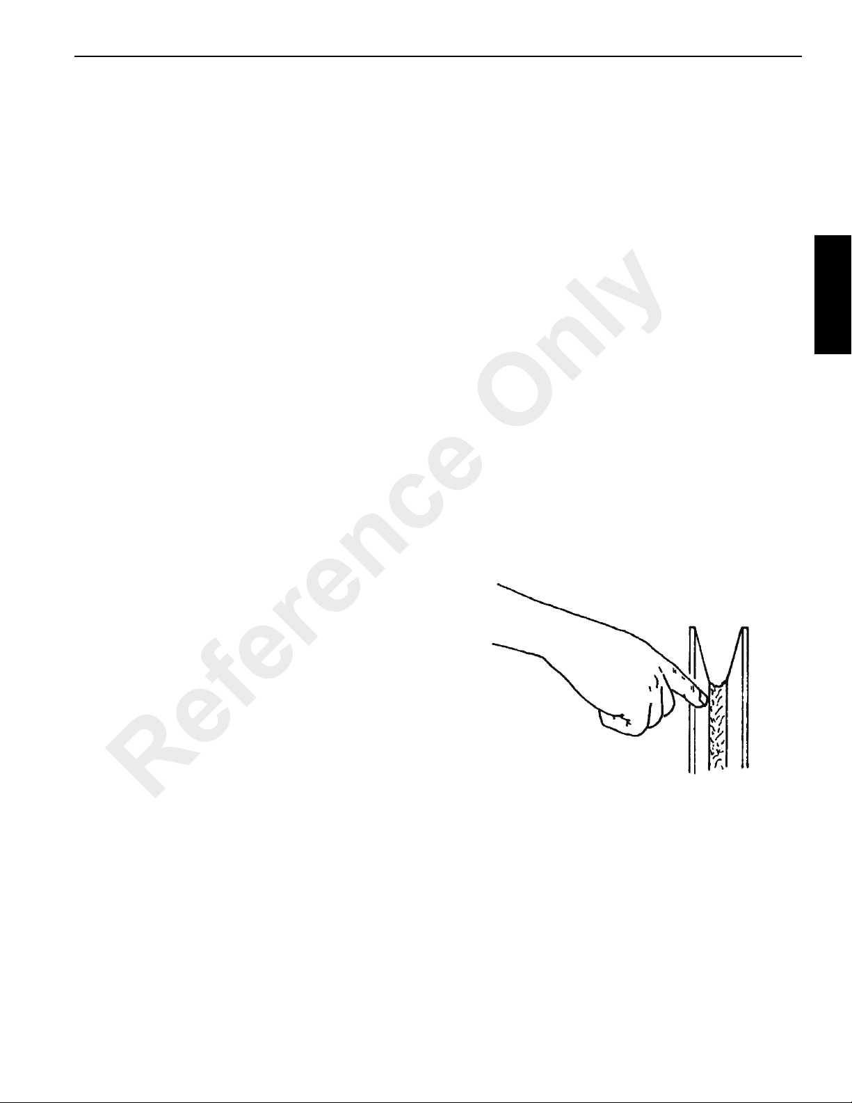
500E2 OPERATORS MANUAL SAFETY PRECAUTIONS
2
periodically. Refer to the Service Manual for more
information.
• In the U.S.A., regular inspections of the wire rope and
keeping of permanent records signed by a qualified
person are required by OSHA for almost every wire rope
application. The purpose of the inspection is to
determine whether or not a wire rope may continue to be
safely used on the application. Inspection criteria,
including number and location of broken wires, wear and
elongation, have been established by OSHA, ANSI,
ASME and similar organizations. See the Service
Manual for inspection procedures.
When inspecting wire ropes and attachments, keep all
parts of your body and clothing away from rotating hoist
drums and all rotating sheaves. Never handle the wire
rope with bare hands.
Some conditions that lead to problems in wire rope
systems include:
- Sheaves that are too small, worn or corrugated
cause damage to a wire rope.
- Broken wires mean a loss in strength.
- Kinks permanently damage a wire rope and must be
avoided.
- Wire ropes are damaged by knots. Wire rope with
knots must never be used.
- Environmental factors such as corrosive conditions
and heat can damage a wire rope.
• When a wire rope has been removed from service
because it is no longer suitable for use, it must not be
reused on another application.
When installing a new rope:
• Keep all parts of your body and clothing away from
rotating hoist drums and all rotating sheaves.
• Never handle the wire rope with bare hands.
• Follow proper instructions for removing rope from a reel.
• Apply back tension to the storage/payoff reel of the new
rope to insure tight, even spooling onto the hoist drum.
• Operate the new rope - first through several cycles at
light load and then through several cycles at
intermediate load to allow the rope to adjust to operating
conditions.
When using a wedge socket:
• Always inspect socket, wedge, and pin for correct size
and condition.
• Do not use parts that are damaged, cracked, or
modified.
• Assemble the wedge socket with live end of rope aligned
with the centerline of pin and assure proper length of tail
(dead end) protrudes beyond the socket.
Sheaves
- Lack of lubrication can significantly shorten the
useful life of a wire rope.
- Contact with electrical wires and resulting arcing will
damage a wire rope.
• An inspection should include verification that none of the
specified removal criteria for this usage are met by
checking for such things as:
- Surface wear; nominal and unusual.
- Broken wires; number and location.
- Reduction in diameter.
Reference Only
- Rope stretch (elongation).
- Integrity of end attachments.
- Evidence of abuse or contact with another object.
- Heat damage.
- Corrosion.
NOTE: A more detailed wire rope inspection procedure is
given in the Service Manual.
Inspect the boom nose and hook block sheav es fo r proper
operation, excessive wear, and damage every 50 hours or
weekly. Inoperable, damaged and/or worn sheaves cause
rapid deterioration of wire rope.
Ensure sheaves carrying ropes that can be momentarily
unloaded are equipped with close fitting guards or other
devices to guide the rope back into the groove when the load
is reapplied. Ensure sheaves in the lower load block are
equipped with close fitting guards that will prevent the ropes
from becoming fouled when the block is lying on the ground
with loose ropes.
National Crane Published 10-20-2011 Control # 111-05 2-15
Page 28

SAFETY PRECAUTIONS OPERATORS MANUAL 500E2
To attain maximum wire rope life and minimize hook block
rotation, it is recommended that even numbers o f parts-ofline be used in multiple-part reeving whenever possible.
The use of nylon (nylatron) sheaves, as compared with
metallic sheaves, may change the replacement criteria of
rotation-resistant wire rope.
NOTE: The use of cast nylon (nylatron) sheaves will
Batteries
Battery electrolyte must not be allowed to contact the skin or
eyes. If this occurs, flush the contacted area with water and
consult a doctor immediately .
When checking and maintaining batteries, exercise the
following procedures and precautions:
• Wear safety glasses when servicing batteries.
substantially increase the service life of wire rope.
However, conventional rope retirement criteria
based only upon visible wire breaks may prove
inadequate in predicting rope failure. The user of
cast nylon sheaves is therefore cautioned that a
retirement criteria should be established based
upon the user’s experience and the demands of his
application.
• If equipped, disconnect battery with the battery
disconnect switch before disconnecting the ground
battery cable.
• Do not break a live circuit at the battery terminal.
• Do not short across the battery posts to check charge.
• Maintain battery electrolyte at the proper level. Check
• If applicable to your crane, check battery test indicator
• Check battery condition only with proper test equipment.
Disconnect the ground battery cable first when removing
a battery and connect it last when installing a battery.
Short circuit, spark, or flame could cause battery
explosion.
the electrolyte with a flashlight.
on maintenance-free batteries.
Batteries shall not be charged except in an open, well-
ventilated area that is free of flame, smoking, sparks,
and fire.
Reference Only
Engine
Fuel the crane only with the engine turned off. Do not smoke
while fueling the crane. Do not store flammable materials on
the crane.
Be familiar with the location and use of the nearest fire
extinguisher.
Be careful when checking the engine coolant level. The fluid
may be hot and under pressure. Sh ut do wn the eng in e a nd
allow the radiator time to cool before removing the radiator
cap.
Shut down the engine and disconnect the battery before
performing maintenance. If unable to do so for the task
required, keep hands clear of the engine fan and other
moving parts while performing maintenance.
Be careful of hot surfaces and hot fluid s when perf orming
maintenance on or around the engine.
Do not use ether to start the engine on cranes equipped with
intake manifold grid heaters.
TR ANSPORTING THE CRANE
Before transporting the crane, check the suitability of the
proposed route with regard to the crane height, width, length,
and weight.
Check load limits of bridges on the travel route and ensure
they are greater than the combined weight of the crane and
transporting vehicle.
When loading or unloading the crane on a trailer or railroad
car, use a ramp capable of supporting the weight of the
crane.
Ensure the crane is adequately secured to the transporting
vehicle.
Before transporting the crane on a road or high way, first
check state and local restrictions and regulations.
When using hookblock tie downs, excessive loading can be
applied by pulling the cable too tight, particularly when
reeved with multiple part lines. When the cable is hooked
into the hookblock tie down, the cable should be merely
“snugged-up” with slack provided at the center line of sheave
to anchor point. Care must be exercised anytime any crane
function is being performed while the cable is hooked into the
hookblock tie down. Do not draw cable taut.
TRAVEL OPERATION
Only the crane operator shall occupy the crane when
traveling.
When traveling, the boom should be completely retracted
and lowered to the travel position and the turntable pin swing
lock should be engaged. If equipped with boom rest, lower
the boom into the boom rest and engage the turntable lock.
Strictly adhere to the guidelines and restrictions in the Load
Chart for pick and carry operations.
This machine is manufactured with no axle suspension
system. Traveling at high speeds, especially on rough
ground, may create a bouncing affect that can result in loss
of control. If bouncing occurs, reduce travel speed. (RT and
Shuttle Lift Only)
2-16 Published 10-20-2011 Control # 111-05
Page 29

500E2 OPERATORS MANUAL SAFETY PRECAUTIONS
2
Death or serious injury could result from being crushed by
revolving tires.
“Stunt” driving and “horse-play” are strictly prohibited. Never
allow anyone to hitch a ride or get on or off a moving crane.
Follow the instructions in this manual when preparing the
crane for travel.
If using a boom dolly/trailer, thoroughly read and understand
all the steps and safety precautions in this manual for setup
and travel.
When driving the crane, ensure the cab is level, if equipped
with a tilting cab.
Secure the hook block and other items before mov ing the
crane.
Watch clearances when traveling. Do not take a chance of
running into overhead or side obstructions.
When moving in tight quarters, post a signal p erso n to he lp
guard against collisions or bumping structures.
Before traveling a crane, check suitability of proposed route
with regard to crane height, width, and length.
Never back up without the aid of a signal person to verify the
area behind the crane is clear of obs tructions and/or
personnel.
On cranes equipped with air-operated brakes, do not attempt
to move the crane until brake system air pressure is at
operating level.
Check load limit of bridges. Before traveling across bridge s,
ensure they will carry a load greater than the crane’s weight.
If it is necessary to take the crane on a road or highway,
check state and local restrictions and regulations.
Keep lights on, use traffic warning flags and signs, an d u se
front and rear flag vehicles when necessary . Check state and
local restrictions and regulations.
Always drive the crane carefully obeyin g speed limits and
highway regulations.
Stay alert a t the wheel.
If equipped, ensure that the hoist access platform hand rail
and step are in the travel configuration.
Slopes:
- Pick and carry on level surfaces only.
- Refer to the Operation Section for more detailed
information on traveling on slopes.
- Driving across a slope is dangerous, as unexpected
changes in slope can cause tip over. Ascend or
descend slopes slowly and with caution.
- Ascend or descend slopes with the boom pointing
up the slope.
- When operating on a downhill slope, reduce travel
speed and downshift to a low gear to permit
compression braking by the engine and aid the
application of the service brakes.
Reference Only
National Crane Published 10-20-2011 Control # 111-05 2-17
Page 30

SAFETY PRECAUTIONS OPERATORS MANUAL 500E2
WORK PRACTICES
Personal Considerations
Always adjust the seat and lock it in position, and fasten the
seat belt securely before you start the engine.
Do not wear loose clothing or jewelry that can get caught on
controls or moving parts. Wear the protective clothing and
personal safety gear issued or called for by the job
conditions. Hard hat, safety shoes, ear protectors, reflective
clothing, safety goggles, and heavy gloves may be required.
Crane Access
Working at elevated heights without using proper fall
protection can result in severe injury or death.
Always use proper fall protection as required by local,
state or federal regulations.
You must take every precaution to ensure you do not slip
and/or fall off the crane. Falling from any elevation could
result in serious injury or death.
Never exit or enter the crane cab or deck by any other means
than the access system(s) provided (i.e., steps and grab
handles). Use the recommended hand-holds and steps to
maintain a three-point contact when getting on or off the
crane.
If necessary, use a ladder or aerial work platform to access
the boom nose.
Do not make modifications or additions to the crane’s access
system that have not been evaluated and approved by
Manitowoc Crane Care.
Do not step on surfaces on the crane that are not approved
or suitable for walking and working. All walking and working
surfaces on the crane should be clean, dry, slip-resistant,
and have adequate supporting capacity. Do not walk on a
surface if slip-resistant material is missing or excessively
worn.
Do not use the top of the boom as a walkway.
Do not step on the outrigger beams or outrigger pads (floats)
to enter or exit the crane.
Use the hoist access platform (if equipped) when working in
the hoist area.
Wear shoes with a highly slip-resistant sole material. Clean
any mud or debris from shoes before entering the crane cab/
operator’s station or climbing onto the crane superstructure.
Excessive dirt and debris on the hand-holds, access steps,
WARNING
Fall Hazard!
Reference Only
or walking/working surfaces could cause a slipping accident.
A shoe that is not clean might slip off a control pedal during
operation.
Do not allow ground personnel to store their personal
belongings (clothing, lunch boxes, water coolers, and the
like) on the crane. This practice will prevent ground
personnel from being crushed or electrocuted when they
attempt to access personal belongings stored on the crane.
Job Preparation
Before crane use:
• Barricade the entire area where the crane is working and
keep all unnecessary personnel out of the work area.
• Ensure that the crane is properly equipped including
access steps, covers, doors, guards, and controls.
• Conduct a visual inspection for cracked welds, damaged
components, loose pins/bolts, and wire connections.
Any item or component that is f ound to be loose or
damaged (broken, chipped, cracked, worn-through, etc.)
must be repaired or replaced. Inspect for evidence of
improper maintenance (consult your Service Manual).
• Check for proper functioning of all controls and operator
aids (e.g. LMI).
• Check all braking (e.g. wheel, hoist, and swing brakes)
and holding devices before operation.
You must ensure that the outriggers and stabilizers are
properly extended and set before performing any lifting
operations. On models equipped with outriggers that can be
pinned at the mid-extend position, the outriggers must also
be pinned when operating from the mid-extend position.
Clear all personnel from the outrigger area before extending
or retracting the outriggers. Carefully f ollow t he pro ce du res
in this Operator’s Manual wh en ex tending o r ret racting the
outriggers. Death or serious injury could result from improper
crane set up on outriggers.
Be familiar with surface conditions and the presence of
overhead obstructions and power lines.
Working
Operator shall be responsible for all operations under his/her
direct control. When safety of an operation is in doubt,
operator shall stop the crane’s functions in a controlled
manner. Lift operations shall resume only after safety
concerns have been addressed or the continuation of crane
operations is directed by the lift supervisor.
Know the location and function of all machine controls.
Make sure all persons are away from th e crane and the
Travel Select Lever is in the “N” (Neutral) position with the
parking brake engaged before starting the engine.
2-18 Published 10-20-2011 Control # 111-05
Page 31

2
500E2 OPERATORS MANUAL SAFETY PRECAUTIONS
Sparks from the crane’s electrical system and/or engine
exhaust can cause an explosion. Do not operate this crane
in an area with flammable dust or vapors, unless good
ventilation has removed the hazard.
Carbon monoxide fumes from the engine exhaust can cause
suffocation in an enclosed area. Good ventilation is very
important when operating the crane.
Before actuating swing or any other crane function, sound
the horn and verify that all personnel are clear of rotating and
moving parts.
Never operate the crane when darkness, fog, or other
visibility restrictions make operation unsafe. Never operate a
crane in thunderstorms or high winds.
Always be aware of your working environment during
operation of the crane. Avoid contacting any part o f the crane
with external objects.
Clear all personnel from the counterweight and
superstructure area before removing the counterweight.
Keep unauthorized personnel clear of the working area
during operation.
Only the crane operator shall occupy the crane when in
operation.
You must always be aware of everything around the crane
while lifting or traveling. If you are unable to clearly see in the
direction of motion, you must post a look out or signal person
before moving the crane or making a lift. Sound the h orn to
warn personnel
Operate the crane only from the operator’s seat. Do not
reach in a window or door to operate any controls.
Operate the crane slowly and cautiously, looking carefully in
the direction of movement.
A good practice is to make a “dry run” without a load before
making the first lift. Become familiar with all factors peculiar
to the job site.
Ensure the wire rope is properly route d on the ho ok block
and boom nose and that all rope guards are in place.
Reference Only
Lifting
Use enough parts of line for all lifts and check all lines,
slings, and chains for correct attachment. To obtain
maximum lifting capacities, the hook block must be set up
with enough parts of line. Too few parts of line can result in
failure of the wire rope or hoist. No less than three wraps of
wire rope should remain on the hoist drum. When slings, ties,
hooks, etc., are used, make certain they are correctly
positioned and secured before raising or lowering the loads.
Be sure the rigging is adequate before lifting. Use tag lines
when possible to position and restrain loads. Personnel
using tag lines should be on the ground.
Be sure good rigging practices are being used. Refuse to
use any poorly maintained or damaged equipment. Never
wrap the hoist cable around a load.
If using a clam bucket, do not exceed 8 0% of the crane’s
capacity.
Make certain the boom tip is centered directly over the load
before lifting.
Ensure that all slings, ties, and hooks are correctly placed
and secured before raising or lowering the load.
Be sure the load is well secured and attached to the hook
with rigging of proper size and in good condition.
National Crane Published 10-20-2011 Control # 111-05 2-19
Page 32

SAFETY PRECAUTIONS OPERATORS MANUAL 500E2
Check the hoist brake by raising the load a few inches,
stopping the hoist and holding the load. Be sure the hoist
brake is working correctly before continuing the lift.
When lowering a load always slow down the load’s descent
before stopping the hoist. Do not attempt to change speeds
on multiple-speed hoists while the hoist is in motion.
Watch the path of the boom and load when swinging. Avoid
lowering or swinging the boom and load into ground
personnel, equipment, or other objects.
Lift one load at a time. Do not lift two or more separately
rigged loads at one time, even if the loads are within the
crane’s rated capacity.
Never leave the crane with a load suspended. Should it
become necessary to leave the crane, lower the load to the
ground and stop the engine before leaving the operator’s
station.
Remember, all rigging equipment must be considered as
part of the load. Lifting capacities vary with working areas. If
applicable, permissible working areas are listed in the Load
Chart. When swinging from one working area to another,
ensure Load Chart capacities are not exceeded. Know your
crane!
Stop the hook block from swinging when unhooking a load.
Swinging rapidly can cause the load to swin g out and
increase the load radius. Swing th e lo ad slo wly. Swing with
caution and keep the load lines vertical.
Look before swinging your crane. Even though the original
setup may have been checked, situations do change.
Never swing or lower the boom into the carrier cab (if
applicable).
Do not pull posts, pilings, or submerged articles. Be sure the
load is not frozen or attached to the ground before lifting.
Never push or pull loads with the crane’s boom; never drag a
load.
Do not subject crane to side loading. A side load can tip the
crane or cause it to fail structurally .
If the boom should contact an object, sto p immediat ely and
inspect the boom. Remove the crane from service if the
boom is damaged.
When lifting a load the boom may deflect causing the load
radius to increase—this condition is made worse when the
boom is extended. Ensure weight of load is within crane’s
capacity on Load Chart.
Avoid sudden starts and stops when moving the load. The
inertia and an increased load radius could tip the crane over
or cause it to fail structurally .
Use tag lines (as appropriate) for positioning and restraining
loads. Check the load slings before lifting.
Be sure everyone is clear of the crane and work area before
making any lifts.
Never swing over personnel, regardless of whether load is
suspended from or attached to the boom.
Hand Signals
A single qualified signal person shall be used at all times
when:
• Working in the vicinity of power lines.
• The crane operator cannot clearly see the load at all
times.
• Moving the crane in an area or direction in which the
operator cannot clearly see the path of travel.
At all times use standardized hand signals - previously
agreed upon and completely understood by the operator and
signal person.
If communication with the signal person is lost, crane
movement must be stopped until communications are
restored.
Keep your attention focused on the crane’s operation. If for
some reason you must look in another direction, stop all
crane movement first.
Obey a signal to stop from anyone.
Reference Only
2-20 Published 10-20-2011 Control # 111-05
Page 33

2
500E2 OPERATORS MANUAL SAFETY PRECAUTIONS
Reference Only
National Crane Published 10-20-2011 Control # 111-05 2-21
Page 34

SAFETY PRECAUTIONS OPERATORS MANUAL 500E2
!
BOOM EXTENSION
To avoid death or serious injury, follow the procedures in this
manual during erection, stowage, and use of the boom
extension.
Install and secure all pins properly.
Control movement of boom extension at all times.
Do not remove right side boom nose pins unless boom
extension is properly pinned and secured on front and rear
stowage brackets.
T o avoid death or serious injury, follow procedures in Load
Chart, safety, and operation manuals during erection,
stowage and use of boom extension. Install and secure all
pins properly and control boom extension movement at all
times.
Do not remove all the pins from both front and rear stowage
brackets unless the boom extension is pinned to the right
side of the boom nose.
Properly inspect, maintain, and adjust boom extension and
mounting.
When assembling and disassembling boom extension
sections, use blocking to adequately support each section
and to provide proper alignment.
Stay out side of boom extension sections and lattice work.
Watch for falling or flying pins when they are being removed.
PARKING AND SECURING
Boom Extension Hazard!
DANGER
WARNING
When parking the crane and leaving it unattended follow
the instructions in Section 3 of this manual.
Failure to comply with these instructions may cause death
or serious injury
When parking on a grade, apply the parking brake and chock
the wheels.
Tipping Hazard!
Reference Only
Section 3 of this manual provides instructions for parking and
securing a crane when it is to be left unattended. These
instructions are intended to allow the crane to be placed in
the most stable and secure position. However, Manitowoc
recognizes that certain jobsite conditions may not permit the
boom and boom extension of a crane to be fully lowered to
the ground. When a qualified person at a jobsite determines
that it is not practical to lower the boom to the ground, we
recommend the following additional instructions be followed:
• The crane should be left in the smallest, most stable,
valid operational configuration that the job site
practically allows.
• The crane can not be left running, with a load on the
hook, or in erection mode, or in wind conditions in
excess of allowed values.
• The boom should be retracted as far as is practical, the
crane configured in as stable a configuration as possible
(boom angle, superstructure orientation, boom
extension angle, etc.)
• In high winds the boom and boom extensions should be
lowered, or secured. Changing weather conditions
including but not limited to: wind, ice accumulation,
precipitation, flooding, lightning, etc. should be
considered when determining the location and
configuration of a crane when it is to be left unattended.
SHUT-DOWN
Use the following steps when shutting down the crane:
• Engage the parking brake.
• Fully retract and lower the boom.
• Engage the swing lock pin or 360 degree swing lock.
• Place controls in neutral position.
• Shut down the engine and remove the ignition key.
• Chock the wheels, if not on outriggers.
• Lock the operator’s cab (if applicable) and install vandal
guards, if used.
In cold weather, never park the crane where the tires can
become frozen to the ground.
COLD WEATHER OPERATION
Cold weather operation requires additional c aution o n the
part of the operator .
Check operating procedures in this manual for cold weather
starting.
Don’t touch metal surfaces that could freeze you to them.
Clean the crane of all ice and snow .
Allow ample time for hydraulic oil to warm up.
In freezing weather, park the crane in an area where it
cannot become frozen to the ground. The drive line can be
damaged when attempting to free a frozen crane.
If applicable to your crane, frequently check all air tanks for
water in freezing weather.
2-22 Published 10-20-2011 Control # 111-05
Page 35

500E2 OPERATORS MANUAL SAFETY PRECAUTIONS
2
If applicable to your crane, always handle propane tanks
according to the supplier’s instructions.
Never store flammable materials on the crane.
If cold weather starting aids are provided on your crane, use
them. The use of aerosol spray or other types of starting
fluids containing ether/volatiles can cause explosions or fire.
T EMPERATURE EFFECT S O N HOOK BLOCKS
The following information applies to Gunnebo Johnston
crane hook blocks:
“Never use a crane block in extreme
temperatures...Sudden failure can occur.
Crane blocks shall not be heated above 180 degrees F.
Craneblock Working Load Limit is valid between 180
degrees F and service temperature given on the
identification tag with normal lifting precautions.
Additional lifting precautions are required below the service
temperature given on the identification tag because cold
temperture begins to affect the crane block material
properties.
Lifting above 75% of the Working Load Limit (WLL), at
temperatures between the service temperature given on the
identification tag and -40 degrees F, must (be) done at a
slow and steady rate to avoid stress spikes common in
normal hoisting dynamics.
75% of the WLL must not be exceeded, when lifting in
temperatures below -40 degrees F.”
T EMPERATURE EFFECT S ON HYDRAULIC CYLINDERS
Hydraulic oil expands when heated and contracts when
cooled. This is a natural phenomena that happens to all
liquids. The coefficient of expansion for API Group 1
hydraulic oil is approximately 0.00043 cubic inches per cubic
inch of volume for 1°F of temperature change. Thermal
contraction will allow a cylinder to retract as the
hydraulic fluid which is trapped in the cylinder cools.
The change in the length of a c ylinde r is p rop ortion al to t he
extended length of the cylinder and to the change in
temperature of the oil in the cylinder. For example, a cylinder
extended 25 ft in which the oil cools 60°F would retract
Reference Only
approximately 7 3/4 in (see chart below). A cylinder
extended 5 feet in which the oil cools 60°F would only retract
approximately 1 1/2 in. The rate at which the oil cools
depends on many factors and will be more noticeable with a
larger difference in oil temperature verses the ambient
temperature.
Thermal contraction coupled with improper lubrication or
improper wear pad adjustments may, under certain
conditions, cause a “stick-slip” condition in the boom. This
“stick-slip” condition could result in the load n ot moving
smoothly. Proper boom lubrication and wear pad adjustment
is important to permit the boom sections to slide freely. Slow
movement of the boom may be und ete cted by the op erat or
unless a load is suspended for a long period of time. To
minimize the effects of thermal contraction or “Stick-slip” it is
recommended that the telescope control lever is activated
periodically in the extend position to mitigate the effects of
cooling oil.
If a load and the boom is allowed to remain stationary for a
period of time and the ambient temperature is cooler than the
trapped oil temperature, the trapped oil in the cylinders will
cool. The load will lower as the telescope cylinder(s) retracts
allowing the boom to come in. Also, the boom angle will
decrease as the lift cylinder(s) retracts causing an increase
in radius and a decrease in load height.
This situation will also occur in reverse. If a crane is set up in
the morning with cool oil and the daytime ambient
temperature heats the oil, the cylinders will extend in similar
proportions.
Table 2-2 and Table 2-3 have been prepared to assist you in
determining the approximate amount of retrac tion/ ex ten sion
that may be expected from a hydraulic cylinder as a result of
change in the temperature of the hydraulic oil inside the
cylinder. The chart is for dry rod cylinders. If the cylinder rod
is filled with hydraulic oil, the contra ction ra te is some what
greater.
NOTE: Operators and service personnel must be aware
that load movement, as a result of this phenomena,
can be easily mistaken as leaking cylinder seals or
faulty holding valves. If leaking seals or faulty
holding valves are suspected to be the problem,
refer to Service Bulletin dealing with testing
telescope cylinders. (Bulletin 98-036 applies to
TMS700 and bulletin G06-005A applies to RT890
and RT9130.
T able 2-2: Boom Drif t Chart (Cylinder length change in inches)
National Crane Published 10-20-2011 Control # 111-05 2-23
Page 36

SAFETY PRECAUTIONS OPERATORS MANUAL 500E2
Coeff. = 0.00043
(in
3
/in3/ °F)
STRO KE Temperature Change (°F)
(FT.)102030405060708090100
5 0.260.520.771.031.291.551.812.062.322.58
10 0.52 1.03 1.55 2.06 2.58 3.10 3.61 4.13 4.64 5.16
15 0.77 1.55 2.32 3.10 3.87 4.64 5.42 6.19 6.97 7.74
20 1.03 2.06 3.10 4.13 5.16 6.19 7.22 8.26 9.29 10.32
25 1.29 2.58 3.87 5.16 6.45 7.74 9.03 10.32 11.61 12.90
30 1.55 3.10 4.64 6.19 7.74 9.29 10.84 12.38 13.93 15.48
35 1.81 3.61 5.42 7.22 9.03 10.84 12.64 14.45 16.25 18.06
40 2.06 4.13 6.19 8.26 10.32 12.38 14.45 16.51 18.58 20.64
45 2.32 4.64 6.97 9.29 11.61 13.93 16.25 18.58 20.90 23.22
50 2.58 5.16 7.74 10.32 12.90 15.48 18.06 20.64 23.22 25.80
55 2.84 5.68 8.51 11.35 14.19 17.03 19.87 22.70 25.54 28.38
60 3.10 6.19 9.29 12.38 15.48 18.58 21.67 24.77 27.86 30.96
Length c hange in inches = Stroke ( Ft.) X Temperature Chan ge ( °F) X Coeff. ( in
3
/in3/ ° F) X 12 in/ft
Coeff. = 0.000774
(1/ °C)
18 69.66 139.32 208.98 278.64 348.30 417.96 487.62 557.28 626.94 696.60 766.26
T able 2-3BoomDrif t Chart (Cylinder length change in millimeters)
STROKE Temperature Change (°C)
(m) 5 10 15 20 25 30 35 40 45 50 55
1.5 5.81 11.61 17.42 23.22 29.03 34.83 40.64 46.44 52.25 58.05 63.86
3 11.61 23.22 34.83 46.44 58.05 69.66 81.27 92.88 104.49 116.10 127.71
4.5 17.42 34.83 52.25 69.66 87.08 104.49 121.91 139.32 156.74 174.15 191.57
6 23.22 46.44 69.66 92.88 116.10 139.32 162.54 185.76 208.98 232.20 255.42
7.5 29.03 58.05 87.08 116.10 145.13 174.15 203.18 232.20 261.23 290.25 319.28
9 34.83 69.66 104.49 139.32 174.15 208.98 243.81 278.64 313.47 348.30 383.13
10.5 40.64 81.27 121.91 162.54 203.18 243.81 284.45 325.08 365.72 406.35 446.99
12 46.44 92.88 139.32 185.76 232.20 278.64 325.08 371.52 417.96 464.40 510.84
13.5 52.25 104.49 156.74 208.98 261.23 313.47 365.72 417.96 470.21 522.45 574.70
15 58.05 116.10 174.15 232.20 290.25 348.30 406.35 464.40 522.45 580.50 638.55
16.5 63.86 127.71 191.57 255.42 319.28 383.13 446.99 510.84 574.70 638.55 702.41
THIS PAGE BLANK
Length change in mm = Stro k e (m) X T em perat ure Change ( °C) X Coeff. (1/ °C) X 1000 mm/m
Reference Only
2-24 Published 10-20-2011 Control # 111-05
Page 37

2
500E2 OPERATORS MANUAL SAFETY PRECAUTIONS
OVERLOAD INSPECTION
This information supplements the Load Moment Indicator
(LMI) manual supplied with each Grove crane.
When the LMI system has acknowledged an overload on
your crane, you must carry out specified inspections on
the crane.
These inspections apply only to overloads up to 50%. For
overloads of 50% or higher, crane operation must be
stopped immediately and Crane Care must be conta cted
for corrective action.
To avoid an accident caused by overload damage to
your crane:
• Perform the inspections outlined in this
publication for overloads up to 50%.
• Stop operating the crane and contact Manitowoc
Crane Care immediately for overloads of 50% and
higher.
NOTE: If your crane is equipped with CraneSTAR, an
overload warning will be posted to the web site
for review by the crane owner.
Overload warnings do NOT indicate real time
events! Warnings could be sent 24 hours (or
more) after the actual event.
WARNING
Overload Hazard!
Reference Only
National Crane Published 10-20-2011 Control # 111-05 2-25
Page 38

SAFETY PRECAUTIONS OPERATORS MANUAL 500E2
4
8
1
7
5
6
1
2, 3
9, 10
9, 10
Boom Inspection
Reference Only
2-26 Published 10-20-2011 Control # 111-05
Page 39

2
500E2 OPERATORS MANUAL SAFETY PRECAUTIONS
Overload less than 25%
Sheaves,
1
Rope Guides
Collar-Wear
2
Pads, Pad
Retainers
Overload from 25% to 49%
Sheaves,
1
Rope Guides
Collar-Wear
2
Pads, Pad
Retainers
3 Collar-welds Inspect all for damage.
4 Pinning Areas Inspect all for cracks.
Inspect all for damage.
Inspect for damage.
Inspect all for damage.
Inspect all for damage.
Telescopic
5
Sections
Lift Cylinder
6
Head Area
Turret-Base
7
Section
8 Jib Section
9 Welds Inspect for cracks.
10 Paint
Inspect for bent or twisted sections. Check the boom
for straightness.
Inspect for bends or cracked welds.
Inspect for cracked welds.
Inspect for bent or twisted section. Check for
straightness.
Inspect for cracked paint which could indicate twisted,
stretched, or compressed members.
Reference Only
National Crane Published 10-20-2011 Control # 111-05 2-27
Page 40

SAFETY PRECAUTIONS OPERATORS MANUAL 500E2
2
7
1
3
8
10,11
6
5
4
9
Superstructure Inspection
Reference Only
2-28 Published 10-20-2011 Control # 111-05
Page 41

500E2 OPERATORS MANUAL SAFETY PRECAUTIONS
2
Overload less than 25%
1 Lift Cylinder Inspect for leaking.
2 Wire Rope Inspect all for damage.
Turntable
3
Bearing
Overload from 25% to 49%
1 Lift Cylinder Inspect for leaking.
2 Wire Rope Inspect all for damage.
Turntable
3
Bearing
4 Hoist/Drums Inspect each for damage.
5 Hoist Brakes Brakes must hold rated line pull.
Bearing Main
6
Boom Pivot
Pin
Lift Cylinder-
7
Lower Mount
8 Turret Area Inspect for deformation, cracked welds.
Mounting
9
Studs
Check bolts for proper torque.
Check bolts for proper torque.
Inspect for deformation, cracked welds.
Inspect pin and welds.
Check bolts for proper torque.
See topic in Introduction section
of Service Manual.
See topic in Swing section of
Service Manual.
See topic in Introduction section
of Service Manual.
See topic in Swing section of
Service Manual.
10 Welds Inspect for cracks.
11 Paint
Inspect for cracked paint which could indicate twisted,
stretched, or compressed members.
Reference Only
National Crane Published 10-20-2011 Control # 111-05 2-29
Page 42

SAFETY PRECAUTIONS OPERATORS MANUAL 500E2
3
1
1
1
2
2
2
3
3
4
4
5, 6
Carrier Inspection
Reference Only
2-30 Published 10-20-2011 Control # 111-05
Page 43

2
500E2 OPERATORS MANUAL SAFETY PRECAUTIONS
Overload less than 25%
Stabilizer
1
Cylinders
Outrigger
2
Pads
Overload from 25% to 49%
Stabilizer
1
Cylinders
Outrigger
2
Pads
Outrigger
3
Beams
Outrigger
4
Boxes
5 Welds Inspect for cracks.
Inspect for leaking.
Inspect for deformation and cracked welds.
Inspect for leaking.
Inspect for deformation and cracked welds.
Inspect for deformation and cracked welds.
Inspect for deformation and cracked welds.
6 Paint
Inspect for cracked paint which could indicate twisted,
stretched, or compressed members.
Reference Only
National Crane Published 10-20-2011 Control # 111-05 2-31
Page 44

SAFETY PRECAUTIONS OPERATORS MANUAL 500E2
THIS PAGE BLANK
Reference Only
2-32 Published 10-20-2011 Control # 111-05
Page 45

3
500E2 OPERATORS MANUAL OPERATING CONTROLS AND PROCEDURES
SECTION 3
OPERATING CONTROLS AND PROCEDURES
SECTION CONTENTS
Truck Cab Controls . . . . . . . . . . . . . . . . . . . . . . . . 3-1
Power Take-Off. . . . . . . . . . . . . . . . . . . . . . . . . . . 3-1
Park Brake . . . . . . . . . . . . . . . . . . . . . . . . . . . . . . 3-2
Cold Weather Operation. . . . . . . . . . . . . . . . . . . . 3-2
Unattended Crane. . . . . . . . . . . . . . . . . . . . . . . . . . 3-2
Crane Controls . . . . . . . . . . . . . . . . . . . . . . . . . . . . 3-2
Turn . . . . . . . . . . . . . . . . . . . . . . . . . . . . . . . . . . . 3-2
Swing Speed Adjustment . . . . . . . . . . . . . . . . . . . 3-2
Boom . . . . . . . . . . . . . . . . . . . . . . . . . . . . . . . . . . 3-2
Boom Telescope. . . . . . . . . . . . . . . . . . . . . . . . . . 3-2
Hoist . . . . . . . . . . . . . . . . . . . . . . . . . . . . . . . . . . . 3-2
Stabilizers Up/Down . . . . . . . . . . . . . . . . . . . . . . . 3-2
Stabilizers Extend/Retract. . . . . . . . . . . . . . . . . . . 3-2
Outriggers. . . . . . . . . . . . . . . . . . . . . . . . . . . . . . . 3-3
Foot Throttle . . . . . . . . . . . . . . . . . . . . . . . . . . . . . 3-3
Emergency Stop Switch . . . . . . . . . . . . . . . . . . . . 3-3
Horn . . . . . . . . . . . . . . . . . . . . . . . . . . . . . . . . . . . 3-3
Hydraulic Capacity Alert System (HCA) Load
Range Gauge . . . . . . . . . . . . . . . . . . . . . . . . . . . . 3-3
HCA Overload Light . . . . . . . . . . . . . . . . . . . . . . . 3-3
Anti-Two-Block/Jib Overload Light . . . . . . . . . . . . 3-3
Key Override Switch . . . . . . . . . . . . . . . . . . . . . . . 3-3
Override Button. . . . . . . . . . . . . . . . . . . . . . . . . . . 3-3
Load Chart . . . . . . . . . . . . . . . . . . . . . . . . . . . . . . 3-3
Boom Angle Indicator . . . . . . . . . . . . . . . . . . . . . . 3-3
Boom length Indicator . . . . . . . . . . . . . . . . . . . . . . 3-3
Outrigger Status Indicator . . . . . . . . . . . . . . . . . . . 3-3
Hoist System Operation . . . . . . . . . . . . . . . . . . . . . 3-5
Using Multiple Part Lines. . . . . . . . . . . . . . . . . . . . 3-5
General Rules When Operating Hoist . . . . . . . . . . 3-5
Lifting the Load . . . . . . . . . . . . . . . . . . . . . . . . . . . 3-5
Optional Hoist Burst of Speed (BOS) . . . . . . . . . . 3-6
Anti-Two Block System. . . . . . . . . . . . . . . . . . . . . . 3-6
Outrigger Monitoring System (OMS)
(Optional—Standard in North America) . . . . . . . . 3-6
Hydraulic Capacity Alert System . . . . . . . . . . . . . . 3-7
System Description . . . . . . . . . . . . . . . . . . . . . . . . 3-7
Indicator Lights . . . . . . . . . . . . . . . . . . . . . . . . . . . 3-7
HCA Load Range Gauge. . . . . . . . . . . . . . . . . . . . 3-7
HCA System Operation. . . . . . . . . . . . . . . . . . . . . . 3-8
Pressure Sensing Switch. . . . . . . . . . . . . . . . . . . . 3-8
Jib Load Limiting Device . . . . . . . . . . . . . . . . . . . . 3-8
System Description . . . . . . . . . . . . . . . . . . . . . . . . 3-8
System Operation . . . . . . . . . . . . . . . . . . . . . . . . . 3-8
Three Section Boom Operation . . . . . . . . . . . . . . . 3-9
Anti-two-block Weight Installation . . . . . . . . . . . . 3-10
Installing Cable On The Hoist. . . . . . . . . . . . . . . . 3-10
Wedge Socket Installation . . . . . . . . . . . . . . . . . . 3-10
TR UCK CAB CONTROLS
Power T ake-Off
Manual Shift Control
The PTO’s are engaged when the knobs on dash or floor are
pulled out and disengaged when the knobs are pushed in.
The truck gear shift lever must be in neutral and the clutch
depressed whenever the knobs are moved.
Air Shift Control
The PTO is engaged when the switch is moved to apply air to
PTO and disengaged when switch in off positio n. The tr uck
gear shift lever must be in neutral and clutch depressed
when switch is moved. The transmission selector lever must
be returned to “N” for stationary vehicle operation. The
National Crane Published 10-20-2011 Control # 111-05 3-1
Reference Only
power take-off may be disengaged while in any transmission
range provided that the load has first been removed from the
PTO.
Electric Shift Control
Full torque electric shift PTO’s are controlled by a switch. To
operate, disengage the clutch, shift to fourth or fifth gear , and
operate the switch down to engage the PTO or up to
disengage the PTO. Return the gear shift to neutral and
engage the clutch.
Power Shift Control
If the vehicles equipped with automatic transmission, the
power take-off must be engaged with the engine at idle.
Refer to transmission manufacturers instructions for special
procedures.
Page 46

OPERATING CONTROLS AND PROCEDURES OPERATORS MANUAL 500E2
Park Brake
The truck brake must be firmly set before leaving cab to
begin operation. If the ground surface is icy or slick or is
sloped, you may be required to help immobilize the truck with
wheel chocks.
Cold Weather Operation
The following recommendations are for operating National
cranes in very low (i.e., sub-zero) temperatures.
Cranes should have appropriate hydraulic oil, lubricants, and
other auxiliary items required for operation in sub -zero
temperatures. Operate individual crane functions to ensure
they are sufficiently warmed prior to performing a lift.
Only experienced operators should operate cranes at full
rated capacities between 0° F (-18° C) and -40° F (-40° C)
and for derated capacities in colder temperatures to ensure
smooth operation. Shock loading shall be avoided.
Derated capacities for each °C below -40°C
Derate the rated load shown on the capacity charts 3.67
percent for each degree celsius below -40° C.
Derated capacities for each °F below -40°F
complete control of boom rotation, boom elevation, boom
extension, hoist, outriggers, engine foot t hro ttle, th e e ngine
emergency stop switch, and a horn switch. All control
handles except the outrigger controls are positione d in the
same order at both control stations.
Turn
Operate the turn control lever to RIGHT to rotate the boom in
a clockwise direction as viewed from the top of t he crane.
Operate the turn control lever to LEFT to rotate the boom in a
counterclockwise direction as viewed from the top on the
crane.
For cranes NOT equipped with continuous rotation, a
mechanical rotation stop pulls the turn control lever b ack to
the center position when engaged. Boom rotation is stopped
over the front of the chassis. On rear mounted cranes NOT
equipped with continuous rotation, rotate the boom over the
passenger side of the chassis when stowing and unstowing
to prevent immediate contact with the mechanical rotation
stop.
Swing Speed Adjustment
Located on turn motor inside frame. Turn knob in to increase
maximum swing speed. Turn knob out to decrease maximum
swing speed.
Derate the rated load shown on the capacity charts 2 percent
for each degree fahrenheit below -40° F
UNATTENDED CRANE
Changing weather conditions including but not limited to:
wind, ice accumulation, precipitation, flooding, lightning,
etc. should be considered when determining the location
and configuration of a crane when it is to be left
unattended.
Failure to comply with these instructions may cause death
or serious injury .
The configuration in which the crane should be left while
unattended shall be determined by a qualified, designated
individual familiar with the job site, configuration, conditions,
and limitations.
Reference Only
WARNING
Tipping Hazard!
CRANE CONTROLS
The crane is equipped with control stations on each side of
the main frame. Decals on the contro l kno bs or next to the
lever indicate the direction to actuate the controls for the
various unit functions. Each station is complete and provides
Boom
Operate the lever to DOWN to lower the boom. Operate the
lever to
UP to raise the boom.
Boom T elescope
Operate the lever to OUT to extend the boom. Operate the
lever to I
N to retract the boom.
Hoist
Operate the lever to DOWN to payout and lower the loadline.
Operate the lever to
Refer to hoist system operation section for additional
information
UP to reel in and raise the loadline.
DANGER
Payout loadline before extending bo om. Failure t o d o so
will cause the loadline to break or damage the crane.
Stabilizers Up/Down
Operate the lever to DOWN to lower and UP to raise.
Stabilizers Extend/Retract
Operate the lever to extend to move beams out and to retract
to move beams in.
3-2 Published 10-20-2011 Control # 111-05
Page 47

500E2 OPERATORS MANUAL OPERATING CONTROLS AND PROCEDURES
3
Outriggers
Operate the lever to up to raise the outrigger legs. Operate
the lever to down to lower the outrigger legs.
Foot Throttle
Depress the foot throttle to accelerate the truck engine
speed. Release to return to idle speed. Increasing truck
speed increases operating speed.
Emergency Stop Switch
Operate the switch to kill the truck engine under emergency
conditions. Switch must be reset to the “on ” position to
operate truck from cab.
Horn
Operate horn button to warn fellow workers on construction
site of pending movement of crane.
Hydraulic Capacity Alert System (HCA) Load Range Gauge
DANGER
Do not use the Load Range Gauge with a jib. Refer to
“Hydraulic Capacity Alert System” for more information
The HCA Load Range Gauge aids in determining the load
condition of crane. The gauge has three colors on the dial
face: (1) Green OK, (2) Yellow Caution, and (3) Red
Overload.
.
Key Override Switch
Turn key switch to enable or disable HCAS, jib load limiting
device, and A TB override. Some units may be equipped with
an optional manual reset valve which does not have an
override key switch.
Override Button
With the override key switch in the on position, depress the
button to override the HCAS jib load limiting device and the
ATB system. Do not use the override to continue lifting
operations in an overload or two-blocked condition.
Load Chart
This chart shows capacities of crane at various operating
areas and hoist capacities with appropriate reeving.
Boom Angle Indicator
Located on either side of the base boom section and used to
determine main boom angle with respect to horizontal. For
reference only .
Boom length Indicator
Located on either side of the second boom section. The
letters on the intermediate boom lengths correspond to the
letters on the load chart. The length indicators are used to
define boom length and with the load chart and load radius
are used to determine the maximum loads that may be safely
lifted. Actual radius must be measured from the centerline of
rotation.
Outrigger Status Indicator
HCA Overload Light
Indicator light illuminates when HCA detects crane overload.
Boom down, extend out and hoist up functions are disabled
when light illuminates.
Anti-T wo-Block/Jib Overload Light
Indicator light illuminates when a two block or jib overload
conditions detected. On Jib equipped units an Audible Alert
sounds when two-block or jib overload conditions are
detected.
National Crane Published 10-20-2011 Control # 111-05 3-3
Reference Only
The Outrigger Status Indicator is part of the Outrigger
Monitoring System and communicates to th e operato r the
position of the outriggers and stabilizers. The Outrigger
Status Indicator is a bi-color LED located at each control
station. When power is on and the outrigger and stabilizer
beams are extended to a point at which t hey provide
maximum stability (stabilizers beams shall be fully extended
on cranes equipped with Rear Stabilizer Out and Down
(RSOD)), the Outrigger Status Indicator illuminates constant
green, indicating a lift can be made. If power is on and one or
more outrigger or stabilizer beams are not extended to a
position which provides maximum stability, the Outrigger
Status Indicator flashes red, indicating a lift should not be
made. If the Outrigger Status Indicator illuminates constant
red, there is a fault in the OMS.
Page 48

OPERATING CONTROLS AND PROCEDURES OPERATORS MANUAL 500E2
Item Component
1 HCAS Load Range Gauge
2 Boom Up/Down
3Hoist
4 Telescope In/Out
5 Turn Left/Right
6 Emergency Stop Switch
7Horn
8 O/R This Side
9 O/R Other Side
10 Stabilizer This Side
11 Stabilizer Other Side
12 Front Stabilizers
13 HCAS Overload Light
Item Component
14 A2B/Jib Overload Light
15 Boom Angle Indicator
16 Load Chart
17 Swing Speed Adjustment
18 Level Indicator
19 Front Throttle
20
HCA-A TB Override Key
Switch
21 Boom Length Indicator
22 HCA-ATB Override Button
23 Torsion Box
24 Fuse (10 amp)
25 Outrigger Status Indicator
Item Component
21
15
23
19
18
17
16
1
7
6
12
5
4
3
2
11
8
9
14
22
13
20
2
3
4
5
6
8
9
10
11
12
7
1
10
NOTE: Item 20 is located behind the
access door on the operators
console as shown.
24
25
25
Reference Only
3-4 Published 10-20-2011 Control # 111-05
Page 49

500E2 OPERATORS MANUAL OPERATING CONTROLS AND PROCEDURES
3
7636
HOIST SYSTEM OPERATION
The hoist is mounted at the rea r of the boom and has
capacities independent from the rest of the crane The hoist
can normally pull more than the crane itself can withstand.
Therefore, care must be taken to insure that the load being
lifted is within boom rating. To lift some of the heavier loads
on the load chart, it will be necessary to multiple part reeve
the hoist block to increase the lifting capacity of the hoist (the
speeds will be proportionately slower) and remain in the
strength limitations of the hoist and wire rope.
Using Multiple Part Lines
The hoist load rating chart on each machine provides the
information for pull limitations on the hoist with various
applicable part reevings. These ratings are based on
providing the proper operating safety factor on the wire rope
supplied with the machine. Therefore, any replacement rope
must meet the rope specification sections of this manual.
General Rules When Operating Hoist
1. Always payout the loadline while extending the boom.
This will maintain clearance between the boom tip and
loadline hook.
2. Do not rely on the A TB System to eliminate two blocking.
Use the system as a backup to safe operation.
3. Make certain the hoist cables are not twisted or kinked
and that cables are properly seated on the drum and in
the sheaves.
4. Before lifting a load, always make certain that three full
wraps of rope will remain on the drum at all times
throughout the lift.
5. When lifting a load approaching the rated hoist load,
raise the load a few inches and return the control to
neutral to determine if the brake is working properly.
6. Do not drag loads in any direction with the hoist.
7. Never attempt to lift loads which are not loose and free,
such as frozen down material or poles out of ground.
8. Maintain tension on the loadline at all times to prevent
the cable from becoming twisted or kinked or improperly
seated on the hoist drum or sheaves.
Reference Only
Lifting the Load
of the crane and hoist reeving system proceed with lifting the
load.
1. Rotate, extend or move up or down until boom tips
directly over the load.
2. The crane is normally equipped with a rotation stop. It is
important that you be aware of the position of the stop
before lifting in order to assure maximum rotation and
prevent excessive handling of the load.
3. During operations, the controls should always be
metered when beginning or terminating movement to
prevent sudden starting or stopping, which imposes
undue shock loads on the equipment. This is especially
true when handling heavy loads. The control should be
slightly actuated to begin movement and then slowly
increased to desired operating speed. The results
obtained from metering the oil flow with the control lever
can also be aided by carefully coordinating the throttle
control.
4. Lower loadline and attach load.
5. Control load by use of a non-conductive tag line.
6. Do not leave crane unattended with the boom elevated
in operating position. Always secure the boom in the
boom rest before leaving the work area.
After the vehicle and crane have been properly set up and it
has been determined the load to be lifted is within the ratings
National Crane Published 10-20-2011 Control # 111-05 3-5
Page 50

OPERATING CONTROLS AND PROCEDURES OPERATORS MANUAL 500E2
BOS
Handle
Note: Maximum Capacity with “BOS”
• One Part Line - 3000 lb (1361 kg)
• Two Part Line - 6000 lb (2722 kg)
• Three Part Line - 9000 lb (4082 kg)
• Maximum line speed on third layer - 271 FPM
(73mpm), fourth layer - 294 FPM (81 mpm)
Hoist Lever
OPTIONAL HOIST BURST OF SPEED (BOS)
The “Burst of Speed” increases hoist line speed 50% over
normal operation by diverting oil from the multi-bank control
valve to the hoist valve.
The “BOS” is engaged by operating the hoist c ontrol valv e
lever while pulling up on the BOS handle below the hoist
knob. The “BOS” feature should only be operated in a
temporary manner to reduce oil heat build up, prevent truck
PTO overloading, and provide independent operation of the
crane and hoist (normal hoist speed will not decrease when
crane functions are used). If the “BOS” feature is run
continuously or with an overload, damage to the crane or
truck could occur. To start the “BOS” smoothly, first pull up on
the BOS handle then operate the hoist lever. To stop the
“BOS” smoothly, return the hoist lever to its neutral position
then release the BOS handle.
.
If the BOS feature Is run continuously or with an overload,
damage to the crane or truck could occur .
CAUTION
hoist cable and end attachments contact the underside of the
sheave case, whether by hoisting up or extending the boom
without paying out the hoist cable, the hoist cable can be
damaged by crimping or over tensioning.
The anti-two-block system provided on your National Crane
can help prevent cable damage by sensing the position of
the hoist cable end attachments with respect to the sheave
case and disabling the functions that can cause a two block
condition.
The anti-two-block system consists of normally open, work
port unloader valves in the main and hoist control valves.
When the cartridge solenoid is energized, the crane
functions normally, when de-energized, the oil to the boom
extend, boom down, and hoist up crane functions are
diverted to tank. These solenoids are controlled by a limit
switch, which is attached to the boom or jib sheave case.
This switch is held in the closed position by a chain
suspended weight. The weight, which is looped around the
hoist cable, causes the contacts to remain closed until the
hoist cable end attachments contact the weight and release
the tension on the switch. At this point the contacts in the
switch open, breaking electrical continuity through the circuit
provided by the internal anti-two-block cord routed through
the boom. When this continuity is broken, the unloader
cartridges de-energize and divert the function oil to tank. An
indicator light is provided on the control console to alert the
operator when a two-block condition is detected.
On machines equipped with an optional Load Moment
Indicator (LMI) System, the anti-two-block system is integral
with the LMI wiring and display . An audible, visual warning of
the two block condition is provided in the display console.
See LMI Operators Handbook for additional information.
Reference Only
ANTI-T WO BLOCK SYSTEM
With untrained or inexperienced or distracted operators, two
blocking the hoist cable is a very real possibility. When the
3-6 Published 10-20-2011 Control # 111-05
Normal functioning is restored by hoisting down (or retracting
boom) until the weight is once ag ain suspended free ly.
Occasionally if the hoist up and boom extend functions are
operated at maximum speed in the dump mode, the back
pressure induced in the circuit will cause the hoist up or
boom extend functions to creep slightly (with no load on the
hook). Such a condition is not cause for alarm, as the back
pressure is not of sufficient magnitude to damage the cable
or end connections.
OUTRIGGER MONITORING SYSTEM (OMS) (OPTIONAL—STANDARD IN NORTH AMERICA)
The Outrigger Monitoring System (OMS) aids the operator in
ensuring that the crane is properly setup on outriggers and
stabilizers. The OMS utilizes one sensor in each outrigger
and one proximity switch in each horizontally extending
stabilizer to identify when the outriggers and stabilizer beams
are extended to a point in which they provid e maximum
stability.
Page 51

500E2 OPERATORS MANUAL OPERATING CONTROLS AND PROCEDURES
3
The OMS utilizes an LED indicator to commu nicate t o the
operator the position of the outriggers and stabilizers. The
Outrigger Status Indicator is a bi-color LED located at each
control station. When power is on and the outrigger and
stabilizer beams are extended to a point at which they
provide maximum stability (stabilizers beams shall be fully
extended on cranes equipped with Rear Stabilizer Out and
Down (RSOD)), the Outrigger Status Indicator illuminates
constant green, indicating a lift can be made. If power is on
and one or more outrigger or stabilizer beams are not
extended to a position which provides maximum stability, the
Outrigger Status Indicator flashes red, indicating a lift should
not be made. If the Outrigger Status Indicator illuminates
constant red, there is a fault in the OMS.
HYDRAULIC CAPACITY ALERT SYSTEM
System Description
The Hydraulic Capacity Alert System (HCA) is a hydraulically
operated, maximum capacity sensing device that will stop all
of the normal crane functions that cause overload when
maximum capacity is exceeded.
In the event that an over capacity condition occurs, the HCA
is actuated by sensing excessive pressure in the lift cylinder.
The following systems will be inoperative:
• boom down
• extend out
• hoist up
These are the functions that increase the over capacity
condition. This system allows for continued operation of the
hoist down, boom up and boom retract functions, the
functions that normally allow the operator to bring the load to
a shorter operating radius or set the load down in order to
eliminate an over capacity condition. Once the excessive
cylinder pressure has been reduced by bringing the load to a
shorter radius or setting the load down, normal operation can
be resumed. This hydraulic capacity alert system uses the
work port unloader solenoids in the anti-two-block system as
the hydraulic system dump circuit.
The hydraulic capacity alert system has an override switch
and button located on the operator’s console that
momentarily overrides the hydraulic capacity alert and antitwo-block systems and restores power to crane functions.
Reference Only
Indicator Lights
Two indicator lights located on the operator’s console alert
the operator of function power loss and discriminate between
the HCA and the Anti-Two-Block or jib load limiting systems
as the cause of power loss.
CAUTION
Do not use the override to continue lifting operations in an
overload or two blocked condition.
HCA Load Range Gauge
The HCA provides a load range gauge at each operator
station. This gauge has three colors on the dial face: (1)
Green – OK, (2) Yellow – Caution, and (3) Red – Overload.
The gauge is plumbed directly to the lift cylinder and the
indicator position can be used as an aid in determining the
load condition of the crane. The lift control lever must be
moved from boom up position to the neutral position to get
the most accurate reading when using load range gauge.
The load range gauge is provided to aid the operator when
operating near the rated capacity of the crane.
NOTE: The gauge only provides accurate indication when
the lift control lever is in neutral.
The gauge movement is not proportional to the load on the
hook. Its not unusual for the indicator to be in the red area at
less than rated load condition when operating the lift control,
especially during boom down operation
.
CAUTION
Do not use the load range gauge with a jib.
National Crane Published 10-20-2011 Control # 111-05 3-7
Page 52

OPERATING CONTROLS AND PROCEDURES OPERATORS MANUAL 500E2
The load range gauge is provided to aid the operator when
operating near the rated capacity of the crane. The gauge
only provides accurate indication when the lift control lever is
in neutral. The gauge movement is not proport ional to the
load on the hook. It is not unusual for the indicator t o be in
the red area at less than rated load condition when operating
the lift control, especially during boom down operation.
HCA SYSTEM OPERATION
Once an over-capacity conditions reached, th e HCA will not
allow the operator to move the load to a greater radius.
Pressure Sensing Switch
When trip pressure is reached, the pressure sensing switch
breaks electrical continuity to the work port unloader
solenoid in the main control valve.When power is removed
from this solenoid, the unloader valves allow the oil flowing to
hoist up, telescope out and boom down to flow to tank. This
path to tank will prevent further operation of these functions.
When the overload condition is corrected by hoisting down,
retracting the boom, or raising the boom, the pressure
sensing switch allows the work port unloader solenoids to be
powered thereby allowing the crane to function normally .
During the operation at near capacity loads, care must be
taken to operate the controls smoothly or the system may be
shocked into the dump mode prematurely.
Caution should be exercised when operating near 80° of
boom elevation. If the boom lift cylinder is fully extended and
pressurized above trip pressure, the system solenoid will
deactivate and the boom will remain locked at 80°. T o correct
this condition, momentarily actuate the ov erride swit ch an d
boom down approximately 5°. Some units may be equipped
with a Manual Reset Valve Option that can be used to unlock
the unit from 80°. See Controls and Hydraulics Section for
additional description of this system.
The override system consists of a key switch and a
momentary push button switch.The key switch pr ovides
power to the momentary push button switch located on the
console.To momentarily override, activate key switch and
depress push button on console. This will activ ate the work
port unloader solenoid and return power to hoist up,
telescope out, and boom down functions.The override switch
is not to be used during normal use of the crane or as an aid
in using the crane in an overload or anti-two blocked
condition.
Reference Only
JIB LOAD LIMITING DEVICE
System Description
The jib load limiting device is an electro-mechanically
operated, maximum capacity sensing device that stops all
normal crane functions that cause overload when maximum
capacity of the jib is exceeded. In the event that an over
capacity condition occurs, the jib load limiting device is
actuated by sensing excessive force on a load cell which
causes the boom down, extend out, and hoist up functions to
become inoperative. These are the functions that incre ase
the over capacity condition. On jibs with a manually
extendable section, a configuration switch operated by the
extension retaining pin distinguishes between an extended
jib and a retracted jib. This system allows for continued
operation of the hoist down, boom up, and boom retract
functions, the functions that normally allow the operator to
bring the load to a shorter operating radius or set the load
down in order to eliminate an over capacity condition. Once
the excessive force on the load cell has been reduced by
bringing the load to a shorter radius or setting the load down,
normal operation can be resumed. This system uses the
work port unloader solenoid in the anti-two-block system as
the hydraulic system dump circuit.
The jib load limiting system has an override switch and
button located on the operator’s console that momentarily
overrides the hydraulic capacity alert, the jib load limiting
device, and the anti-two-block system and restores power to
crane functions. Two indicator lights located on the
operator’s console alert the o pera to r of fu nctio n power lo ss
and discriminate between the hydraulic capacity alert and
the anti-two-block or jib load limiting systems as the cause of
power loss. In the event of a two-block or jib overload
condition, an audible alarm will sound in addition to the
lighting of the indicator light.
Do not use the override to continue lifting operations in an
overload or two blocked condition.
System Operation
The jib load limiting device will operate as stated in the
System Description Section. Once an over-capacity
condition is reached, the system will not allow the operator to
move the load to a greater radius. The truck may have to be
repositioned closer to the load in order to set the load at the
desired location.
3-8 Published 10-20-2011 Control # 111-05
Page 53

500E2 OPERATORS MANUAL OPERATING CONTROLS AND PROCEDURES
3
Item Component
1. Base
2 Extend Cable
3Tip
4
3
rd
Section
THREE SECTION BOOM
5
2
nd
Section
6 Retract Cable
7
1
st
Section
Item Component
1
6
5
7
4
2
3
When trip force is reached, the jib load limiting device breaks
electrical continuity to the work port unloader solenoid in the
main control valve. When power is removed from this
solenoid, the unloader valves allow the oil flowing to hoist up,
telescope out and boom down to flow to tank. This path to
tank will prevent further operation of these function s. Wh en
the overload condition is corrected by hoisting down,
retracting the boom, or raising the boom, the jib load limiting
device allows the work port unloader solenoid to be powered
thereby allowing the crane to function normally .
During operation at near capacity loads, care must be taken
to operate the controls smoothly or the system may be
shocked into the dump mode prematurely.
The override system consists of a key switch and a
momentary push button switch. The key switch p rovides
power to the momentary push button switch located on the
console. To momentarily override, activate key switch and
depress push button on console. This will ac tivate the work
port unloader solenoid and return power to hoist up,
telescope out, and boom down functions. The override
switch is not to be used during normal use of the crane or as
an aid in using the crane in an overload or two-blocked
condition.
These systems do not prevent structural or stability
overloads to the crane or hoist caused by:
1. Freely swinging loads or operating in an out-of-level
condition which will result in excessive side loading.
2. Side loading due to pulling sideways on the boom with
boom rotation or load hoist. Load must always be
directly under boom tip.
3. Sudden load movements from erratic operation of the
crane functions which will result in excessive shock
loading.
4. Improper loadline reeving for loads larger than single
line pull capacity .
5. Extending the boom without first paying out the loadline
which can result in deadheading (two blocking) the
loadline against the boom tip.
6. Loads with lift cylinder fully retracted.
7. Excessive induced loading during auger system
operation.
8. Operation without outriggers and stabilizers fully
deployed or inadequate footing for the outriggers and
stabilizers.
The HCA and the Jib Load Limiting Device are intended to
be used as only aids to prevent overload conditions. Do
not use the Hydraulic Capacity Alert System and the Jib
Load Limiting Device as substitutes for safe operating
practices as out lined in this manual.
Do not expect the Hydraulic Capacity Alert System and th e
Jib Load Limiting Device to detect all possible overload
conditions.
CAUTION
THREE SECTION BOOM OPERATION
A rod-fed, double-acting cylinder, attached to the 1
boom sections, supports and propels the 2nd boom section.
The extend cables attach to the ba se end of the 1
section, are reeved around sheaves attached to the cylinder,
rd
and attach to the base end of the 3
support and extension of the 3
boom section providing
rd
boom section.
st
and 2
st
boom
nd
Reference Only
National Crane Published 10-20-2011 Control # 111-05 3-9
Page 54

OPERATING CONTROLS AND PROCEDURES OPERATORS MANUAL 500E2
The anti-two-block chain must be
installed between the slot in the
weight and the hoist cable.
Anti-two-block Weight
Hoist
Cable
Slot
Chain Length
16 inches (40 cm) Do
not shorten the chain.
Upper Link
Lower Link
FIGURE 3-1
1
2
2
3
7312
7196
The retract cables attach to the tip end of the 1st boom
section and are reeved around sheaves attached to the 2
boom section. They are attached to the base end of t he 3
boom section providing retraction of the 3rd boom section.
This type of boom operation ensures that the 2
section booms extend and retract equally. Proper service
and maintenance is required to insure smoo th and pro per
operation
Anti-two-block Weight Installation
To prevent the h oist cable f rom slipping out of th e ant-twoblock weight, rig the weight as shown below .
nd
nd
and 3
3. Insert the cable through the slot and position around the
anchor wedge (1) Figure 3-1.
rd
NOTE: The end of the cable should be even with the
bottom of the slot for the anchor wedge.
rd
INSTALLING CABLE ON THE HOIST
If cable is wound from the storage drum, the reel should
be rotated in the same direction as the hoist.
NOTE: The cable should preferably be straightened before
Install cable on the hoist drum in accordance with the
following procedure.
1. Position the cable over the boom nose sheave and route
2. Position the hoist drum with the cable anchor slot on top.
installation on the hoist drum.
Reference Only
to the hoist drum.
CAUTION
4. Position the anchor wedge in the drum slot; pull firmly on
the free end (2) of the cable to secure the wedge.
NOTE: If the wedge does not seat securely in the slot,
carefully tap (3) the top of the wedge with a mallet.
5. Slowly rotate the drum, ensuring the first layer of cable is
evenly wound onto the drum.
6. Install the remainder of the cable, as applicable.
WEDGE SOCKET INST ALLATION
1. Properly match socket, wedge and clip to wire rope size.
The wire rope must pass through the “go” ho le in the
wedge. It must not pass through the “no go” hole in the
wedge.
2. Align live end of rope, with center line of pin.
3. Secure dead end section of rope.
4. Tighten nuts on clip to recommended torque. (See
Table)
3-10 Published 10-20-2011 Control # 111-05
Page 55

500E2 OPERATORS MANUAL OPERATING CONTROLS AND PROCEDURES
3
Dead
End
Dead
End
Live End is
Entering
Wrong Side
Live
End
20 x Cable Dia
Minimum
RIGHT
WRONG
Wedge Socket
Torque Value Table
Cable Size (inches) 3/8 7/16 1/2 9/16 5/8 3/4 7/8 1 1-1/8 1-1/4
Torque ft/lbs 45 65 65 95 95 130 225 225 225 360
Torque values shown are based upon clean dry threads free of lubrication.
T erminator Wedge Socket
5. Do not attach dead end to live end or install wedge
backwards.
6. Use a hammer to seat Wedge and Rope as deep into
socket as possible before applying first load.
.
Reference Only
National Crane Published 10-20-2011 Control # 111-05 3-11
Page 56

OPERATING CONTROLS AND PROCEDURES OPERATORS MANUAL 500E2
THIS PAGE BLANK
Reference Only
3-12 Published 10-20-2011 Control # 111-05
Page 57

500E2 OPERATORS MANUAL SET-UP
4
SECTION 4
SET-UP
SECTION CONTENTS
Equipment Familiarization. . . . . . . . . . . . . . . . . . . 4-1
Equipment Checks . . . . . . . . . . . . . . . . . . . . . . . . 4-1
Pre-Operation Inspection and Calibration
Verification . . . . . . . . . . . . . . . . . . . . . . . . . . . . . . 4-1
Work Site Selection . . . . . . . . . . . . . . . . . . . . . . . 4-2
Before Leaving the Cab . . . . . . . . . . . . . . . . . . . . 4-2
Lifting Over the Rear. . . . . . . . . . . . . . . . . . . . . . . 4-2
Lifting Over the Front with a Front Stabilizer. . . . . 4-3
Before Making the Lift. . . . . . . . . . . . . . . . . . . . . . 4-3
Reading and understanding the load Charts. . . . 4-3
Set-Up. . . . . . . . . . . . . . . . . . . . . . . . . . . . . . . . . . 4-4
Operation . . . . . . . . . . . . . . . . . . . . . . . . . . . . . . . 4-4
Definitions . . . . . . . . . . . . . . . . . . . . . . . . . . . . . . . 4-5
Determining Load Capability . . . . . . . . . . . . . . . . . 4-6
Load Determination Examples. . . . . . . . . . . . . . . . 4-6
Jib Operation Safety . . . . . . . . . . . . . . . . . . . . . . . . 4-8
Side Folding-Swing Around Jib Operation. . . . . 4-10
Deployment Procedure . . . . . . . . . . . . . . . . . . . . 4-10
Stowing Procedure . . . . . . . . . . . . . . . . . . . . . . . . 4-10
Jib Maintenance. . . . . . . . . . . . . . . . . . . . . . . . . . 4-11
Jib Removal. . . . . . . . . . . . . . . . . . . . . . . . . . . . . 4-11
Jib Jack Procedures . . . . . . . . . . . . . . . . . . . . . . 4-12
Adjustable Swing Speed Valve . . . . . . . . . . . . . . 4-12
EQUIPMENT FAMILIARIZATION
All members of the crew should become familiar with the
location and operation of controls, the correct operating
procedure, the maximum lifting capacities, and the safety
precautions applicable to the unit before operating. This
crane is a complex piece of equipment and can be
overloaded in many ways. Carefully follow the operating
procedures outlined below and in the inst ruct ional pages of
the load rating chart at the operator’s station.
Equipment Checks
Perform the following checks prior to placing the unit in
operation:
• Inspect for any unusual conditions such as pools of
hydraulic fluid or lubricating oil under the chassis, any
outrigger which may have crept down or up and any
signs of damage or improper maintenance.
• Check that the tires are inflated to the proper pressure.
• Check the level of the hydraulic reservoir .
• Check the operation of the “stop” and horn circuits.
• Check for missing and loose bolts, pins, and ring
retainers
• Check for damaged structural members and welds.
• Check all rope guides and cable keepers.
• Check all sheaves for free turning.
Reference Only
• Check the loadline cable for kinks, broken strands or
other damage in accordance with instructions in the
Lubrication and Maintenance Sections.
• Check to see that the hydraulic hoses and fittings are in
good condition and show no signs of leaking. The hoses
should be free from cuts and abrasions and there should
be no evidence of binding. Any damage or leakage
should be repaired immediately .
• Check HCA, anti-two-block system and jib load limiting
device for proper operation.
NOTE: Consult truck manufacturer’s manual for vehicle
checks.
Pre-Operation Inspection and Calibration Verification
1. Check the electrical wiring connecting the various parts
of the system for physical damage.
2. Check the anti-two-block switches and weights for free
movement.
DANGER
The following tests shall be performed with care to
prevent damage to the machine or injury to personnel.
Proper functioning of the system requires successful
completion of these tests before operating the machine..
National Crane Published 10-20-2011 Control # 111-05 4-1
Page 58

SET-UP OPERATORS MANUAL 500E2
If the operator cannot see the load handling device
approaching the boom nose, he shall have an assistant
(signal person) watch the load handling device. The
operator shall be prepared to stop the machine immediately
should the anti-two-block system not function properly as
indicated by lighting the red warning light, sounding the
audible alarm (jib-equipped cranes) and locking the crane
movements, hoist up, telescope out and boom down.
Check the anti-two-block alarm light and the audible a larm
(jib-equipped cranes) by performing one of th e following
tests:
• By manually lifting the weight attached to the anti-two-
• Slowly raise the main boom load handling device to
• Slowly extend (telescope) the boom to create a potential
If the light and audible alarm (jib-equipped cranes) do not
function as described and the crane movements are not
stopped, the system is not working properly. The
malfunction shall be corrected before operating the crane.
• If the crane is equipped with a boom extension (jib) that
Work Site Selection
Always seek the best possible work site when parking the
crane. An ideal parking location at a job site is firm, level, dry
ground or pavement located in close proximity to the work
station. Avoid uneven, rocky or muddy terrain, steep grades
or locations with unnecessary overhead obstructions .
Location should be selected such that outriggers can be fully
extended and leg comes down on firm level surface.
Particular care must be taken when in the vicinity of
overhead power lines so that proper clearance conditions
can be maintained. Do not select a location at which the
boom could not come within minimum recommended
distance of the power lines at full extension.
block switches. When the weight is lifted, the audible
alarm (jib-equipped cranes) should sound, the an ti-t wo-
block alarm light should light.
create a potential two-block condition. When the load
handling device lifts the weight, the audible alarm (jib-
equipped cranes) should sound, the anti-two-block
alarm light should light and the motion of the load
handling device should be stopped. Lower the load
handling device slightly to eliminate this condition.
two-block condition. When the load handlin g dev ice lifts
the weight, the audible alarm (jib-equipped cranes)
should sound, the anti-two-block alarm light should light
and the boom telescope out function should be stopped.
Lower the load handling device slightly to eliminate this
condition.
CAUTION
is deployed and rigged for work, repeat the test
procedure for the boom extension (jib) anti-two-block
switch.
Reference Only
Its best to select a location on the site such that most of the
lifting can be done over the outrigger support or rear of the
truck.
Before Leaving the Cab
1. Position the truck so that the outriggers can be extended
without encountering obstructions. Set the truck park
brake securely and turn front wheels into the curb.
Wheel chocks may be required under certain conditions.
2. With the gear shift in neutral, depress clutch (if equipped
with a manual transmission), and engage the power
takeoff by pulling out the shifting knob.
3. Bring the hydraulic system up to operating temperature
(oil reservoir warm to the touch) by allowing the system
to operate by actuating the outrigger retract switch with
all outriggers fully retracted.
DANGER
To prevent the crane from tipping over.
• Make sure crane is level.
• Do not operate the boom until all outriggers are
extended and set providing firm support.
• Make sure the tires are clear of ground.
If operating on sloping ground provide blocks. When lifting is
to be done on soft terrain or hot asphalt, support the
outrigger and stabilizer pads with bearing pads. Some
concrete and asphalt surfaces are relatively thin and cannot
support outrigger or stabilizer loading. Concrete can break
through and cause instability .
Variation in chassis, outrigger, and mounting configurations
will cause outrigger foot loading to differ on each crane,
however, outrigger foot loads can be as high as 40,000 lbs
(18,145 kg) when outriggers are at full span (131 psi
(0.9 MPa) on standard outrigger pads). Support surface
bearing capacities vary by a large amount from 833 psi
(5.7 MPa) on bed rock down to 14 psi (0.1 MPa) on soft clay.
Loose sand or soft asphalt will support even less load. It is
imperative that the operator take proper precautions to
insure the outrigger foot has adequate cribbing for existing
soil conditions.
If specific outrigger foot loading is required for an individual
crane, contact National Crane with actual chassis weights
and crane details.
Lifting Over the Rear
Before conducting any boom operations, extend both
outriggers until the chassis weights removed from the
wheels. Level the crane from side-to-side. A level indicator is
provided at either control station. Then extend and lower the
stabilizers to level the crane front-to-back. Again refer to the
4-2 Published 10-20-2011 Control # 111-05
Page 59

500E2 OPERATORS MANUAL SET-UP
4
180°
360°
Block
+
Sling
+
Load
Total Rated
Load
level indicator to insure that the cra ne is properly leveled.
Always keep the load as close to the ground as possible.
Check to ensure that the jib, if so equipped, is stowed
correctly on the first section boom.
Lifting Over the Front with a Front St abilizer
Before Making the Lift
A front stabilizer is required when loads are to be lifted over
the front of the vehicle. Before conducting any boom
operations, extend both outriggers until the chassis weight is
removed from the wheels. Level the crane side-to-side using
the level indicator located at either control station as a
reference. Then extend and lower the rear stabilizers to level
the crane front-to-back. Again refer to the level indicator to
insure that the crane is properly leveled. After the crane is
leveled side-to-side and front-to-back, ex tend the front
stabilizer leg(s) until firm contact is made with the ground.
Always keep the load as close to the ground as possible.
Do not operate outriggers unless they are visible to either
the operator or a designated signal person to avoid
crushing injury
Reference Only
DANGER
1. Check all controls for proper operation by operating
each system through one complete cycle. This is
particularly important after the unit has been serviced or
repaired. If any abnormal operations are detected,
correct the condition before continuing.
2. During all operations, the controls should be metered
when beginning or terminating a movement to prevent
sudden starting or stopping which imposes undue shock
loads on the equipment. This metering can be
performed by metering the control lever and the foot
throttle.
READING AND UNDERSTANDING THE LOAD CHARTS
The structures and components of your unit are designed to
provide satisfactory service if the unit is not loaded in excess
of the maximum rated loads specified on the load chart.
Overloading can create serious potential safety hazards and
can also shorten the service life of your unit. It is important
that you know the weight and radius of any load that you are
attempting to handle. This should be done b y use of a
dynamometer and tape measure or by contacting your
supervisor.
Overloading a crane can cause
many types of failure depending on
the configuration and working
position of the crane, such as
structural damage to almost any part
of the crane, hoist or cable failure
and tipping the unit over.
National Crane Published 10-20-2011 Control # 111-05 4-3
Page 60

SET-UP OPERATORS MANUAL 500E2
The load chart shows the maximum rated loads including
load (weight being lifted), load handling equipment such as
slings, buckets, and downhaul weight that can be handled by
the crane and the hoist. The weight of the lo ad handling
equipment and boom attachments must be deducted from
the maximum load rating shown on the load chart to
determine the payload which can be lifted. Additional
reduction may be necessary to make allowance for such
factors as the effects of freely swinging loads, wind, ground
conditions, out-of-level conditions and operating speeds.
The ratings shown on the outrigger full span load chart are
maximum loads and are based on:
The stability or non shaded areas represent a stability tipping
factor of 85% (Note: For New York City approved units, the
stability or non shaded areas represent a stability tipping
factor of 75%) when:
1. All outriggers are extended with positive contact on firm,
2. The proper amount of counterweight has been installed,
3. The unit is mounted in accordance with factory
4. The weight of load handling devices is considered as a
5. The correct loadline reevings used for the load to be
6. Adverse environmental conditions such as wind are not
7. The operator controls the loads smoothly .
8. Tires are inflated to the proper pressure.
9. The load to be handled does not exceed the maximum
10. The loads are lifted in the proper area around the truck.
- the structural integrity of the crane in shaded areas,
- the stability of the crane in non shaded areas.
level surface, the tires are free of the ground and the
machines level within 1.
if required.
instructions on a vehicle with proper specifications.
part of the load being lifted.
lifted.
present.
capacity at the boom length and loaded radius.
A stability test should have been performed on this crane
and can be repeated by referring to the Installation Section of
the Service Manual.
All capacities are given in direct relationship to the boom
length and loaded radius at which the loads being handled.
• All radii are measured from the centerline of rotation to
• All variances of loads and radii of operation are shown
• Boom angle should be used as reference only to aid in
the loadline with the load suspended.
on the load chart mounted on the main frame.
determining radius.
Reference Only
• The correct loaded radius must be measured and not
exceeded during any point of the lifting operation.
• The placards located at the operators platform for the
purpose of informing the operator wh en a loa d can or
cannot be handled.
• Load ratings cannot be interpolated between load points
shown on the chart in the boom areas.
• When boom length or radius or both are between points
listed on load chart, the smallest load shown at either the
next larger radius or boom length shall be used.
• Capacities of the jib cannot be interpolated between
angles nor at reduced lengths because the strength of
the jib and its attachment point to the boom doe s not
increase when the boom is shortened.
NOTE: Rated loads shown on the load chart pertain to this
machine as originally manufactured and equipped.
Modifications to the machine or use of equipment
that is not factory sp ecified or approve d can be
hazardous. Refer to capacity deduction chart for
weights which must be deducted from rated loads
when accessories are attached to boom or
loadline.
Set-Up
1. Inspect vehicle and crane including crane operation
prior to use each day .
2. Load ratings shown on the chart are maximum allowable
loads with the crane mounted on a factory approved
truck and all outriggers set on a firm level surface so the
crane is level; ensure the Outrigger Status Indicator
illuminates green before making a lift. This crane is not
rated for use without outriggers.
3. Depending on the nature of the supporting surface,
structural supports under the outrigger floats may be
necessary to spread the load to a larger bearing surface.
4. Always level the crane with the level indicator located at
the operator stations located on either side of the crane
frame.
Operation
1. Operation of this equipment in excess of maximum load
rating and disregard of instructions is hazardous. Always
refer to the load chart for load and area limits before
operating the crane. Rated loads at rated radius shall
not be exceeded. Over loading this crane may cause
structural collapse or instability. Do not rely on the HCA
system or the jib load limiting device to weigh the load
and control limiting boom angle and radius. Use these
system as a backup to safe operation.
2. Use the angle indicator as a reference only. When lifting
maximum loads, measure radius.
4-4 Published 10-20-2011 Control # 111-05
Page 61

500E2 OPERATORS MANUAL SET-UP
4
Block
+
Sling
+
Load
Total Rated
Load
Full Capacity
Work Area
3. Rated loads do not exceed 85% of the tipping load as
determined by SAE Crane Stability Test Code J765a
when mounted on a factory recommended truck
NOTE: For New York City approved units, rated load do
not exceed 75% of the tipping load as determined
by SAE Crane Stability Test Code J765a when
mounted on a factory recommended truck.
4. Structural limited ratings on the load chart are shaded.
Stability limited loads are not shaded. Machine will not
always tip before structural damage occurs.
5. Rated loads include the weight of the hook block, slings,
other lifting devices and boom accessories. Their
weights must be subtracted from the listed rated load to
determine the net load that can be lifted.
6. Rated loads are based on
freely suspended loads.
Always position the boom
tip directly over the load
before lifting. No attempt
shall be made to push
down with the boom or
move the load sideways in
any direction by pulling or
dragging the load.
15. Do not allow personnel to ride on hook, hook block, load
or any device attached to the loadline. Use only National
Crane approved baskets.
16. Operate controls slowly and smoothly to avoid damage
to crane or personnel.
17. Boom must be in carrying rack and outriggers fully
retracted for travel.
18. Do not operate crane within 10 feet (3.05m) of live power
lines.
Definitions
Load Radius
Horizontal distance from the centerline of rotation before
loading to the center of the vertical load line or block with
load applied.
Loaded Boom Angle
Loaded boom angle is the angle between the first section
boom and the horizontal, after lifting the rated load at the
rated radius. The boom angle before loading should be
greater to account for deflections. The loaded boom angle
combined with the boom length give only an approximat ion
of the operating radius.
7. The user shall operate at reduced ratings to allow for
adverse job conditions such as soft or uneven ground,
high winds or erratic operation which produce swinging
(side) loads, experience of personnel, two machine lifts,
or other hazardous conditions for safe operation.
8. When boom length or radius or both are between points
listed on load chart, the smallest load shown at either the
next larger radius or boom length shall be used.
9. Do not exceed jib capacities at any reduced boom
length. If Jib is between angle ratings on load chart, the
smallest load shall be used.
10. Its safe to attempt to telescope or retract any load listed
if rating is not exceeded. Capacities at retracted boom
length cannot be telescoped without exceeding ratings.
11. Always pay out loadline before extending boom to avoid
damaging loadline or crane structure.
12. Loads lifted must be within safe hoist capacity as well as
safe crane capacity. Multiple part rope reeving must be
used on loads exceeding hoist single part rated pull. Jibs
are rated for single part use only.
13. Do not operate the boom over personnel or allow them
to walk or stand beneath the boom or load.
14. Do not allow personnel on truck bed or crane frame area
when operating crane.
Reference Only
Working Area
Area measured in a circular arc above the center line of
rotation as shown on the Working Area diagram. If no decal
is present the work areas 360°.
Freely Suspended Load
Load hanging free with no direct external force applied
except by the loadline.
Side Load
Horizontal side force applied to the lifted load either on the
ground or in the air .
National Crane Published 10-20-2011 Control # 111-05 4-5
Page 62

SET-UP OPERATORS MANUAL 500E2
Boom Length
Length of the boom, from boom pivot pin to wire rope on last
main boom section. A decal on either side of the boom
shows when certain boom lengths are reached. The letters
on the intermediate boom lengths correspond to the letters
on the load chart.
Range Diagram
Corresponds to the pictorial in the load chart. The chart
shows the operating radius and height of the unloaded boom
tip at all boom lengths and angles. The chart should be used
as a guide to position unloaded loadline and to det ermine
approximate height to which the load can be lifted.
DETERMINING LOAD CAPABILITY
The following procedure is a typical method which must be
used to determine the crane’s ability to han dle a load. The
crane is equipped with a standard hoist:
1. Determine the weight of the load and load handling
2. Determine the radius from center line of crane rotation to
3. Determine the radius from centerline of crane rotation to
4. Refer to load chart for crane and determine that load and
5. Refer to load chart to determine correct hoist reeving.
Load Determination Examples
equipment.
position of load.
center of point where load is being moved to.
radius of lifting are within capacity of crane.
4. Refer to crane load chart.
Starting point: Assuming the boom is fully retracted [27 ft'
(8.23 m) boom length], the capacity at a 10 ft (3.04 m) radius
is 18,900 lbs (8,573kg).
In order to get the load on the roof, the load must be:
• hoisted from the ground
• swung around the rear of the truck (dead spot in rotation
is over the cab)
• boom extended to 62 ft (18.90 m) extension
• load hoisted to a height that will clear the top of the
building
• boom rotated to the point load is to be placed
• boom tip lowered to 40 ft (12.19 m) radius
• load lowered to building roof.
Ending Point: The load rating at the ending point is 3950 lbs
(1792 kg). The boom will be at 62 ft (18.90m) extension and
the loaded radius is 40 ft (12.19 m).
• The crane has enough capacity at each end of the lift to
allow the lift to be made.
• Refer to hoist load chart. Crane is reeved for single part
line.
• Allowable load for single part lines 7700 lbs (3492 kg)
well above the 2480 lbs (1 124 kg) to be lifted.
• Operator should now proceed to lift the load as smoothly
as possible
.
The following examples are for illustrative purposes only.
The load chart ratings, component weights and dimensional
data may not be the same as the actual unit. Always use
actual information from the crane and job site when planning
a lift.
Example 1
A load is to be lifted from the ground and weighs 2300 lbs
(1043 kg) at a radius of 10 ft (3.04 m). The load will be placed
on the roof of a building at a radius of 40 ft (12.19 m) and a
height of 40 ft (12.19 m) above the ground on the opposite
side of the truck.
1. Determine the load.
Reference Only
Load = 2300 lb (1043 kg)
1 Part Load Block = 150 lb (68 kg)
Sling = 30 lb (14 kg)
Total Load = 2480 lb (1 125 kg)
2. St arting Radius =10 ft (3.04 m)
3. Ending Radius = 40 ft (12.19 m)
CAUTION
This load could not be lifted if the jib were being used on
this machine as maximum capacity of the 23 ft (7 m) jib at
40 ft (12.19 m) radius would only be 1800 lbs (816 kg) at
65°. The capacities remain the same even with the boom
retracted.
The hoist in this example can lift 7700 lbs (3492 kg) while
the boom is only able to withstand 3950 lbs (1792 kg) at
40 ft (12.19 m) radius. Therefore, one could easily
damage the crane by attempting to pull until the h oist
stops with a heavier load.
Example 2
Assume a load of 9000 lbs (4082 kg) at 10 ft (3.04 m) radius
on the ground beside the truck to be picked up, swung over
and placed on the truck bed at an 8 ft (2.43 m) radius from
the crane. Crane is reeved for single part.
1. Weight of load and load handling equipment.
Load = 9000 lb (4082 kg)
1 Part Load Block = 150 lb (68 kg)
4-6 Published 10-20-2011 Control # 111-05
Page 63

500E2 OPERATORS MANUAL SET-UP
4
Sling = 50 lb (22 kg)
Total Load = 9200 lb (4173 kg)
2. St arting Radius = 10 ft (3.04 m)
3. Ending Radius = 8 ft (2.43 m)
4. Refer to crane load chart.
The crane capacity at the 10 ft (3.04 m) radius is 18 ,9 00 lbs
(8,573 kg). At the 8 ft (2.43 m) radius, the capacity is
19,750 lbs (8,960 kg).
The crane capacity is adequate.
5. Refer to hoist load chart.
The capacity of a 1 part line is 7700 lbs (3492 kg), which is
less than load to be lifted.
NOTE: Crane must be reeved for 2 part to lift the 9,000 lbs
(4082 kg) load.
Two p art hoist capacity is 1 5,400 lbs (6985 kg)
After reeving for 2 part line the new Step 1 calculation is the
weight of load and load handling equipment.
2. Starting Radius Given = 30 ft (9.14 m)
3. Ending Radius Given = 40 ft (12.19 m)
4. Refer to Crane load chart.
To reach the load on the roof, the jib must be utilized to clear
the roof with the load.
CAUTION
Do not attempt to deploy the jib until reading and
understanding jib operation information found later in this
section of the manual.
Both the retracted 23' jib length and extended 41' jib length
have the necessary capacity at a 30' (9.14 m) radius. Only
the retracted 23' jib has the capacity at the 40' (12.19 m)
radius to accomplish the task.
Starting Point: With the 23 f t (7 m) jib deployed and the boom
fully extended, the capacity is 2,450 lbs (1111 kg) at a 30 ft
(9.14 m) radius and boom angle of 72.1.
Ending Point: With the main boom still fully extended, the
capacity is 1,800 lbs (816 kg) at a radius of 40 ft (12.19 m)
and boom angle of 65.4.
Load = 9000 lb (4082 kg)
1 Part Load Block = 200 lb (90.7 kg)
Sling = 50 lb (22 kg)
Total Load = 9250 lb (4195 kg)
Example 3
A load of 1500 lbs (680 kg) is to be lifted from the roof of a
building at a radius of 30 ft (9.14 m) and a height of 80 ft
(24.38 m) and placed on the ground on the other side of the
truck at a radius of 40 ft (12.19 m).
1. Weight of load and load handling equipment.
Load = 1500 lb (680 kg)
1 Part Load Block = 150 lb (68 kg)
Sling = 30 lb (14 kg)
Reference Only
Total Load = 1680 lb (762 kg)
NOTE: The capacity of the jib remains the same even with
the main boom retracted. Operate with jib by radius
when main boom is fully extended and operate with
jib by boom angle when main boom is not fully
extended. Do not exceed rated jib capacities at any
reduced boom lengths.
5. Refer to hoist load chart.
The capacity of a 1 part lines 7700 lbs (3492 kg) which is well
above the 1,680 lbs (762 kg) to be lifted.
NOTE: The HCA Load Range Gauge does not provide
accurate indication of overload conditions when
operating with a jib deployed. The HCA will not
prevent the crane from being operated in an
overload condition. The Jib is equipped with a jib
load limiting device which will prevent the jib from
being operated in an overload condition.
The operator should proceed to lift the loa d as s moo th ly as
possible.
National Crane Published 10-20-2011 Control # 111-05 4-7
Page 64

SET-UP OPERATORS MANUAL 500E2
JIB OPERATION SAFETY
1. The anti-two-block switch weight and cord must be
2. Do not lift load with the boom tip when the Jib is pinned
3. Operate with jib by radius when main boom is fully
4. Operate with jib by boom angle when main boom is not
5. Ensure Jib is stowed correctly .
6. Only attempt to swing jib to working or stowed position
7. Crane shall be fully set up according to proper set-up
8. Operate boom and turn functions very slowly and
attached to the jib when deployed.
on the boom tip.
extended. If necessary , increase boom angle to maintain
loaded radius.
When radius is between points listed on load chart, the
load shown at the next longer radius shall be used.
fully extended. Do not exceed rated jib capacities at any
reduced boom lengths.
When angle is between points listed on load chart, the
load shown at next lower boom angle shall be used.
a. Removal of swing around pins, C, without proper
installation of stow pin A and jib swing pin B, may
allow jib to fall off.
b. Extending boom with jib stowed and failure to
remove swing pins, C, will damage unit upon
extension.
when boom is horizontal, stow pin A and jib swing pin B,
are removed and swing pins, C, are in place. Jib could
swing uncontrollably if boom is not horizontal.
procedures outlined previously when stowing or
unstowing jib.
carefully when using jib since jibs can increase boom
length by 50%.
9. Area where jib swings around must be clear of
obstructions and power lines when stowing and
unstowing jib.
10. Use safety glasses when necessary.
11. Do not extend/retract boom unless boom is horizontal
when stow pin A and jib swing pin B are removed during
stowing or unstowing procedures.
12. Always put spring clips in pins to ensure that they will
stay in place.
13. When the jib is stowed, the boom can not be fully
retracted if a boom tip attachment option is installed.
CAUTION
• Boom tip attachment can contact jib in stowed
position when boom is fully retracted.
• Contact can cause damage to boom extension
system and jib stow system.
• Boom must be left extended 0.5 ft (0.2 m) to prevent
contact.
• Boom attachment must be removed for retracted
boom lifting operations.
Manually Extendable Jib:
1. Extension retaining pin, E, must always be installed
when operating.
2. All swing around (stow and unstowing) operations shall
be done with jib retracted and pinned.
3. The extendable section may slide out of 1
the mechanical stop when pin E is removed. Keep
personnel clear of area.
st
section jib to
Reference Only
4-8 Published 10-20-2011 Control # 111-05
Page 65

500E2 OPERATORS MANUAL SET-UP
4
A Stop Pin B Jib Swing Pin C1 Jib Deployment
C2 Jib Deployment D Stow Loop F Load Line Attachment Point
Jib in Stow Position
JIb in Operating position
A Stow C2 Jib Deployment
B Jib Swing D S tow Loop
C Swing Around E Extension
Retaining
C1 Jib Deployment F Load Line
Attachment
Point
Reference Only
National Crane Published 10-20-2011 Control # 111-05 4-9
Page 66

SET-UP OPERATORS MANUAL 500E2
SIDE FOLDING-SWING AROUND JIB OPERATION
Deployment Procedure
1. Using boom telescope function, fully retract boom.
2. Using lift function, lower boom to allow for easier access
NOTE: When lowering the boom below horizontal, two
3. Install pins C1 in upper and lower jib ears. Install retainer
4. Locate the stowed position of pins C2. If the pins are in
5. Remove jib swing Pin B from top ear of jib.
6. Remove stow Pin A from ramp/side stow bracket
7. Attach tag line to sheave case end of jib.
to jib deployment pins C1 and C2.
persons may be required. With the t elescope
control in neutral, the boom can creep out when
below horizontal.
spring clips. These pins will be used as a pivot point to
swing jib into the deployed position.
jib attachment holes or boom sheave case jib holes,
remove pins from storage location.
assembly on jib and stow in Stow Loop D and install
spring clip.
15. Route loadline over jib sheave and install keeper. Install
line block to end of loadline.
16. Remove anti-two-block weight/chain assembly from
boom tip switch and install on jib tip switch. Be certain to
use keeper provided with switch.
17. Disconnect twist lock quick coupler on anti-two-block
cord going to boom anti-two-block switch and attach to
quick coupler on jib anti-two-block wire on rear of jib
between the upper and lower jib ears.
18. Install jib swing pin B and spring clip into jib ears.
19. For manually extendable jibs, pull extension retention
pin E, and extend second section out by pulling on
sheave case. The second section jib, as it extends, will
hit a mechanical stop that allows for extension pin E
installation. Install pin E and spring clip.
STOWING PROCEDURE
8. Using lift function, raise boom to a horizontal position.
9. Using telescope function, slowly extend boom
approximately one foot. This procedure will pull the jib
out of the stow bracket.
Use Caution during this step. The Jib is free to swing
away from the boom upon boom extension.
10. Using tag line, swing jib into deployed position.
11. Remove cable keeper pins from boom sheave case and
12. Pivot jib into place, visually aligning the upper C2 pin
13. Using jib jack, (Refer to Jib Jack Procedures in this
14. Using hoist function, un-spool enough loadline to reeve
jib. Remove hook block. Pivot jib slightly to allow for
loadline to be removed from boom sheave case.
Remove loadline from boom sheave case and place in
an area to minimize possible damage.
Reference Only
holes. Install upper C2 pin and spring clip. A slight
hammer strike may be necessary to install pins. Always
use proper eye protection during this step.
chapter) position jib so that lower C2 pin holes are in
alignment and install lower C2 pin and spring clip.
loadline over jib sheave case. Keep slight tension on
loadline to avoid bird caging of loadline on hoist drum.
DANGER
1. Using lift function, lower boom so that jib tip is close to
the ground.
NOTE: When lowering the boom below horizontal, two
persons may be required. With the telescope
control in neutral, the boom can creep out when
below horizontal.
2. For manually extendable jibs, pull extension retention
pin and fully retract extendable 2
section. Retraction of 2nd section may be facilitated by
nd
section jib into the 1
st
4-10 Published 10-20-2011 Control # 111-05
Page 67

500E2 OPERATORS MANUAL SET-UP
4
attaching loadline wedge socket to attachment point F
on the jib sheave case. Slowly activate the hoist up
function until the 2
3. Reinstall extension retention pin through the 1
section jib assembly and install spring clip.
4. Remove loadline from jib sheave case. Place loadline in
area to avoid possible damage from stow procedure.
5. Disconnect twist lock anti-two-block wire connector at
rear of 1
anti-two-block switch connector on boom tip. Move antitwo-block weight assembly to boom tip switch.
6. Attach tag line to sheave case end of jib.
7. Remove spring clips from pins C2 on both upper and
lower jib ears.
8. Remove pins C2 from upper and lower jib ears. Do not
remove C1 pins at this time. C1 pins will be used as a
pivot point to swing jib into stow position. A slight
hammer strike may be necessary to remove pins.
Always use proper eye protection during this step.
Utilization of the jib jack at this time will aid in pin hole
alignment to facilitate pin removal.
9. Using lift function, raise boom to a horizontal position.
10. Using extend function, extend boom approximately 1
foot.
11. Using tag line attached to jib sheave case, slowly swing
jib into stow position (parallel with 1
Pins C1 are the jib pivot points during this operation.
st
section jib. Connect twist lock connector to
nd
sections fully retracted
st
and 2
st
section boom).
15. Remove pins C1 from upper and lower jib ears. A slight
hammer strike may be necessary to remove pins.
Always use proper eye protection during this step.
nd
16. Reinstall loadline over boom sheave case.
DANGER
Visually check all pin positions to assure Jib is fully
retracted into side stow brackets, jib stow attachments
secure, and all pins and spring clips are in their proper
locations. Failure to properly secure the jib during stowing
and erecting may allow the jib to fall. Serious personal
injury or death could result.
WARNING
Always have at least one, if not both of the following in
place at all times:
• Side stow bracket completely engaged into stow
hook with stow pin A properly in place.
• Both pins C1 in upper and lower jib holes properly in
place through mating holes on boom tip
Jib Maintenance
1. Lubricate sheave pin on jib with grease gun containing
chassis grease weekly .
2. Check for free rotation of jib sheave daily when using jib.
CAUTION
Use caution when swinging jib to avoid unnecessary
impact with 1st section boom
12. Install jib swing pin B with spring clip through jib ear and
boom sheave case holes. This pin will keep the jib
assembly in line (parallel) with the 1
B does not retain the jib in its stowed position on the 1
section boom.
13. Using boom telescope function, slowly retract boom.
The ramp/side stow bracket assembly on the side of the
st
1
section boom, first lifting the jib and then engaging the jib
side stow bracket and the boom hook completely upon
full retraction of the boom.
14. Install stow pin A with spring clip into the ramp/side stow
bracket assembly on the jib. Complete engagement of
stow brackets and proper installation of pin A is critical
for a secure jib stow attachment.
Reference Only
section jib will engage the hook on the side of the 1
st
section boom. Pin
3. Lubricate jib sheave case pivot pin with grease gun
containing chassis grease monthly .
Jib Removal
Should jib removal from the boom become necessary,
proceed as follows
st
CAUTION
Jib Weights
The 41 ft (12.49 m) jib weights 960 lbs (435 kg) at 129 in.
st
(328 cm) when retracted from mounting pin holes.
1. Unstow and swing jib into position on the boom tip
according to Steps 1 - 10 in the preceding jib deployment
section.
2. Support and raise the jib at its balance point and remove
the two swing around pins. Jib is now free of boom.
3. To install, proceed in reverse order of removal.
National Crane Published 10-20-2011 Control # 111-05 4-11
Page 68

SET-UP OPERATORS MANUAL 500E2
Jib Jack Procedures
The Jib Pin alignment device (Jib Jack) is an aid for installing
the fourth or “last” jib pin when setting up a jib. This device
has been designed to line up the bottom jib pin hole on the
left side of the crane the hole in the boom ear.
The jib pin alignment device consists of a hydraulic jack
mounted horizontally on the underside of the jib. A handle for
the jack is provided and is installed above the jack on the
side of the jib.
Prior to using the Jib Jack, complete Steps 1 to 12 in the
“Side Folding-Swing Around Deployment Procedure”.
1. Remove jack handle and using the flattened end, close
2. Insert the round end of the handle into the handle sleeve
3. Continue to pump slowly until jib pin holes exactly
4. After all jib pins are installed, relieve jack.
The jib pin alignment device is also useful when removing
the “fourth” pin. Use the jib jack to relieve jib weight induced
pressure on the “fourth” pin and it will be much easier to
remove.
Once the jib has been erected or stowed, it is important that
the jack handle be properly placed back on its stowage
hooks and that the cotter key be properly placed in the
stowage hook to retain the handle on the hook.
jack release valve by turning the handle clockwise until it
is firmly closed.
and pump jack until ram contacts boom sheave case.
aligned with hole in boom ear. At this time the final jib pin
can be easily tapped into position.
If hole alignment is “over shot” due to jacking too far, the
jack can simply be relieved and the process repeated.
To relieve the jack, use the flattened end of jack handle
to slowly turn relief valve counter clockwise no more
than one full turn.
When Jib is stowed on side of crane, always leave ram and
handle sleeve pushed all the way down to reduce exposure
to rusting.
ADJUSTABLE SWING SPEED VALVE
This crane is equipped with an adjustable swing speed
valve. This valve allows the operator to limit the maximum
swing speed of the machine to suit operator preference or
varying applications.
An adjustment dials located on the swing holding valve
mounted on the swing motor inside the crane frame. The
valve has an adjustment screw with a lock collar. Loosen the
lock collar when adjusting the speed, then tighten the lock
collar to maintain swing speed limit setting. The adjustment
dial allows the maximum swing speed to be reduced as
required.
Avoid “shock loads” created by quickly opening and
closing the release while jack is under load. This may
result in overloading of the hydraulic circuit an d po ssib le
damage to the jack.
Reference Only
CAUTION
4-12 Published 10-20-2011 Control # 111-05
Page 69

500E2 OPERATORS MANUAL LUBRICATION PROCEDURE AND CHARTS
5
SECTION 5
LUBRICATION PROCEDURE AND CHARTS
SECTION CONTENTS
General . . . . . . . . . . . . . . . . . . . . . . . . . . . . . . . . . . 5-1
Lubricants . . . . . . . . . . . . . . . . . . . . . . . . . . . . . . . 5-1
Arctic Conditions Below -18°C (0°F). . . . . . . . . . . 5-1
Chassis Grease. . . . . . . . . . . . . . . . . . . . . . . . . . . 5-1
Extreme Pressure Multipurpose Gear Lubricant
(EPGL) . . . . . . . . . . . . . . . . . . . . . . . . . . . . . . . . . 5-1
Open Gear Lubricant . . . . . . . . . . . . . . . . . . . . . . 5-2
Chassis Grease Low Temp. . . . . . . . . . . . . . . . . . 5-2
Anti-wear Additives. . . . . . . . . . . . . . . . . . . . . . . . 5-2
Hydraulic OIL . . . . . . . . . . . . . . . . . . . . . . . . . . . . 5-2
Standard Hydraulic Oil . . . . . . . . . . . . . . . . . . . . . 5-2
Intermediate Hydraulic Oil. . . . . . . . . . . . . . . . . . . 5-2
Wide Range Intermediate Hydraulic Oil. . . . . . . . . 5-2
Arctic Hydraulic Oil. . . . . . . . . . . . . . . . . . . . . . . . . 5-2
Lubrication Points. . . . . . . . . . . . . . . . . . . . . . . . . . 5-2
Surface Protection for Cylinder Rods . . . . . . . . . . 5-3
Internal Cable Sheave Lubrication. . . . . . . . . . . . . 5-5
Inner Boom Pad Lubrication . . . . . . . . . . . . . . . . . 5-5
Side and Bottom Boom Wear Pad Lubrication . . . 5-5
Hoist Gearbox Oil . . . . . . . . . . . . . . . . . . . . . . . . . 5-6
Hoist Brake Oil. . . . . . . . . . . . . . . . . . . . . . . . . . . . 5-6
Hydraulic Oil Reservoir Level. . . . . . . . . . . . . . . . . 5-7
Wire Rope Lubrication . . . . . . . . . . . . . . . . . . . . . . 5-7
GENERAL
Following a designated lubrication procedure is important to
ensure a maximum crane life. The procedures and
lubrication charts in this section in clude infor matio n on t he
types of lubricants used, the location of the lubrication points,
the frequency of lubrication, and other information. This
section does not include lubrication requirements for the
truck chassis. Refer to truck service manual for this
information.
The service intervals specified are for normal operation
where moderate temperature, humidity, and atmospheric
conditions prevail. In areas of extreme conditions, the
service periods and lubrication specifications should be
altered to meet existing conditions. For information on
extreme condition lubrication, contact your local Nation al
Crane Distributor or Manitowoc Crane Care.
Lubricants
Specific recommendations of brand and grade of lubricants
are not made here due to regional availability, operating
conditions, and the continual development of improved
products. Where questions arise, contact your National
Crane Distributor or Manitowoc Crane Care.
Reference Only
Arctic Conditions Below -18°C (0°F)
In general, petroleum based fluids developed especially for
low temperature service may be used with satisfactory
results. However, certain fluids, such as halogenated
hydrocarbons, nitro hydrocarbons, and phosphate ester
hydraulic fluids, might not be compatible with hydraulic
system seals and wear bands. If you are in doubt about the
suitability of a specific fluid, check with your authorized
Manitowoc distributor or Manitowoc Crane Care.
NOTE: All fluids and lubricants may be purchased by
contacting the Manitowoc Crane Care Parts
Department.
Regardless of temperature and oil viscosity, always use
suitable start-up procedures to ensure adequate lubrication
during system warm-up.
Chassis Grease.
Lubricating grease of proper consistency is to be applied
periodically at relatively frequent intervals with grease guns
through grease fittings. Minimum apparent viscosity of 300
SUS (Saybolt Universal Seconds) at 100° F (38° C) is
recommended.
Extreme Pressure Multipurpose Gear Lubricant (EPGL)
This gear lubricant is compounded to achieve high load
carrying capacity and meet the requirements of either APIGL-5 or MIL-L-2105C. Unless otherwise specified,
SAE 80W-90 viscosity may be used for yea r r ou nd se rvic e.
Low temperature usage is restricted as follows:
National Crane Published 10-20-2011 Control # 111-05 5-1
Page 70

LUBRICATION PROCEDURE AND CHARTS OPERATORS MANUAL 500E2
SAE Viscosity
Number
75W -40 (-40)
80W -15 (-26)
85 +10 (-12)
90 +20 (-7)
140 +40 (+5)
Minimum Ambient T emperature
F (C)
250 +50 (+10)
Open Gear Lubricant
This is a special high-graphite adhesive lubricant that helps
to eliminate fretting corrosion, is water resistant, and forms a
dry lubrication film which does not attract dust. Lubricant
meets NLGI Class 1-2 specifications.
Chassis Grease Low T emp
This special grease for low temperature remains plastic at 60°F (-51°C) with melting point of 280°F (138°C). The
grease is a heavy duty extreme pressure type lubricant
(Lubricate Low Temp or equal).
Anti-wear Additives
Excessive wear in the system may cause a loss in volumetric
efficiency, and may cause shutdowns for maintenance. An
efficient anti-wear oil protects the components against
rusting, resists oxidation and helps prevent wear.
Hydraulic OIL
Intermediate Hydraulic Oil
(-10°F to 80°F) (-23°C to 27°C)
For colder operating environments, the standard fluid may be
replaced with a Low Service Temperature Multi Viscosity
Hydraulic Oil with High Viscosity index 175+.
Wide Range Intermediate Hydraulic Oil.
(-30°F to 80°F) (-34°C to 27°C)
For even colder operating conditions, the standard fluid may
be replaced with a petroleum based fluid developed
especially for colder environments.
Arctic Hydraulic Oil.
(-10°F and below) (-23°C and below)
In general, petroleum based fluids developed especially for
low temperature service may be used with satisfactory
results. However, certain fluids, such as halogenated
hydrocarbons, nitro hydrocabons and phosphate ester
hydraulic fluids might not be compatible with hydraulic
system seals and wear bands. Arctic hydraulic oil is not
recommended for service in ambient temperatures above
32°F (0°C).
If you are in doubt about the suitability of a specific fluid,
check with your authorized National Crane distributor or
Manitowoc Crane Care.
NOTE: All fluids and lubricants may be purchased by
contacting the Manitowoc Crane Care Parts
Department.
Oil in a hydraulic system serves as the power transmission
medium, system lubricant and coolant. Selection of the
proper oil is essential to ensure satisfactory system
performance and life. The most important factors in selecting
an oil for hydraulic service are viscosity and anti-wear
additives.
Operation of the crane with incorrect hydraulic oil in sub
freezing temperature (below 32°F, 0°C) can cause
damage to the extend cylinder.
CAUTION
Reference Only
Standard Hydraulic Oil
Above 10°F (-12°C)
The factory fill standard hydraulic oil is SAE grade 10W-20
Hydraulic Oil. This fluid is acceptable for operating
temperatures above -12°C (10°F).
LUBRICATION POINTS
A regular frequency of lubrication must be established based
on component operating time. The most efficient method of
keeping track of lube requirements is to maintain a job log of
crane usage.
All oil levels are to be checked with the crane parked on a
level surface in transport position, and while the oil is cold,
unless otherwise specified. On plug type check points, the oil
levels are to be at the bottom edge of the fill port.
Over lubrication of non-sealed fittings will not harm the
fittings or components, but under lubrication shortens
lifetime.
Worn grease fittings that do not hold a grease gun, or th os e
that have a stuck check ball, must be replaced.
When wear pads or rotation bearings are lubricated, cycle
the components and lubricate again to ensure complete
lubrication of the entire wear area.
5-2 Published 10-20-2011 Control # 111-05
Page 71

500E2 OPERATORS MANUAL LUBRICATION PROCEDURE AND CHARTS
5
CAUTION
Lubrication intervals (page 5-2) are to be used only as a
guide. Actual intervals should be formulated by the
operator to correspond accordingly to conditions such as
continuous duty cycles and/or hazardous environments.
Surface Protection for Cylinder Rods
Steel cylinder rods include a thin layer of chrome plating on
their surfaces to protect them from corroding. How ever,
chrome plating inherently has cracks in its structure which
can allow moisture to corrode the underlying steel. At typical
ambient temperatures, hydraulic oil is too thick to penetrate
these cracks. Normal machine operating temperatures will
allow hydraulic oil to warm sufficiently to penet rate these
cracks and if machines are operated daily, protect the rods.
Machines that are stored, transported, or used in a corrosive
environment (high moisture, rain, snow, or coastline
conditions) need to have the exposed rods protected more
frequently by applying a protectant. Unless the machine is
Symbol Description Manitowoc Lube Specification
EP-MPG Extreme Pressure Multipurpose Grease - Lithium Soap Base, NLGI Grade 2. A6-829-003477
EP-3MG Extreme Pressure Moly Grease A6-829-015304
GL-5 Extended Service Interval Gear Lubricant - SAE Grade 80W-90 A6-829-012964
AFC - 50/50 50/50 Blended Fully Formulated Antifreeze/Coolant, SAE J1941, ASTM D6210 A6-829-101130
HYDO Hydraulic Oil - Must meet ISO 4406 cleanliness level 17/14 A6-829-006444
EO-15W/40 Engine Oil - SAE 15W-40, API Service Classification CI-4 or better A6-829-003483
EP-OGL Open Gear Lubricant, CEPLATTYN 300 S pray, NLGI Grade 1-2 A6-829-102971
AGMA EP-4 Extreme Pressure Gear Lubricant. A6-829-100213
WRL Wire Rope Lubricant A6-829-015236
LTG Low T emperature Grease, NLGI Grade 1 A6-829-225828
operated daily, exposed rod surfaces will corrode. Some
cylinders will have rods exposed even when completely
retracted. Assume all cylinders have exposed rods, as
corrosion on the end of the rod can ruin the cylinder .
It is recommended that all exposed cylinder rods be
protected using Boeshield
Manitowoc CraneCARE has Boeshield T-9 Premium Metal
Protectant available in 12 oz. cans that can be ordered
through the Parts Department.
NOTE: Cylinder operation and inclement weather will
remove the Boeshield protectant. Inspect
machines once a week and reapply Boeshield to
unprotected rods.
The following describe the lubrication points and gives the
lube type, lube interval, lube amount, and application of
each. Each lubrication point is numbered, and this number
corresponds to the index number sho wn on the Lu bric ation
Chart. Lube description and symbols are found in tables
below.
®
T-9 Premium Metal Protectant.
Reference Only
National Crane Published 10-20-2011 Control # 111-05 5-3
Page 72

LUBRICATION PROCEDURE AND CHARTS OPERATORS MANUAL 500E2
4
14
4
19
16
20
18
5
10a
10b
6
23
11
7
19
20
21
3
2
9a
9b
15
NOTE: T orque dif fuser to
51 lb-ft (69 Nm). Openings
must face bottom of tank.
1
22
Oil Fill/Breather
13
18
Oil Drain
12
Item Application
1 Hydraulic oil reservoir HYDO Check fill change Weekly , semi-annually, as required
Reference Only
2 Oil filter, magnetic plug, hydraulic oil reservoir Change or clean
3 Breather, hydraulic oil reservoir Clean Monthly
4 Sheave pins: boom (3 plcs), jib (1 pl) EP-MPG Grease gun Weekly
5 Wire rope (loadline) EP-OGL Brush or spray Semi-Annually
6 Boom pivot pin EP-MPG Grease gun Monthly
7 Lift cylinder pins - 2 ea. EP-MPG Grease gun Monthly
8 Swing bearing (turret) (not shown) EP-MPG Grease gun Weekly
9a Pump drive U-Joint 2 ea. EP-MPG Grease gun Monthly
9b Pump spline shaft (direct mount) EP-MPG
10a Hoist gearbox. SAE 90 EP Change/check and fill Every 1000 hours or 6 months
5-4 Published 10-20-2011 Control # 111-05
Recommended
Lubricant
Remove pump and apply to
shaft or grease gun
Procedure Frequency
After first 40 hrs. as indicated by
gauge thereafter.
Semi-Annually
Page 73

500E2 OPERATORS MANUAL LUBRICATION PROCEDURE AND CHARTS
5
Item Application
10b Hoist brake HYDO Change/check and fill Every 1000 hours or 6 months
11 Control linkage EO-15W/40 Oil Can As Required
12 Swing drive gearbox GL-5 Change After 100 operating hours
13 Swing gear teeth EP-OGL Spray Can Monthly
14 Boom extension LTG Brush, roller or grease gun Monthly or as required
15 Outrigger beams, bottom, sides LTG Brush or roller Monthly or as required
16 Extension cables (not shown) WRL S pray or brush
17 Boom Wear Pads (not shown) EP-MPG Brush or roller Monthly or as required
18 Swing Motor Pinion Bearing EP-MPG Grease gun Sparingly every 50 hours
19 Extend Sheaves EP-3MG Grease gun Weekly
Retract Sheaves: Extend the boom until the
20
retract sheave grease holes are visible through
the access holes along side of boom.
21 Diffuser strainer, Hydraulic oil reservoir Clean Semi-Annually with oil change
22 Magnetic plug, hydraulic oil reservoir Clean At oil filter service interval
23 Continuous rotation swivel (optional) EP-MPG Grease gun Monthly
Internal Cable Sheave Lubrication
DANGER
Do not, under any circumstances, work at an elevated
height without using proper fall protection as required by
local, state or federal regulations
Recommended
Lubricant
EP-3MG Grease gun Weekly
1. Extend boom until grease access hole (Item 19 on the
2. Check alignment between the 2
Procedure Frequency
Any time boom is disassembled or
5 years
Lubrication Points diagram) becomes visible on s ide of
nd
2
section.
and the 3
become aligned, the end of the extend cable sheave pin
is visible and accessible for lubrication.
rd
section access holes. When these holes
nd
section access hole
The lubrication points on the sheaves are not equipped with grease fittings (zerks) and will require a grease gun adapter to accomplish the task.
Special T ools:
Nozzle or needle grease gun fitting:
• 0.25 inch (6.35 mm) diameter nozzle grease gun tip
(National P/N 955047).
• Contact the Manitowoc Crane Care to obtain this tip.
• Observation through the sheave case for the extend
sheaves and the hoist mount for retract
NOTE 1: To determine the amount of grease required,
visually inspect the sheaves. From the front of
Reference Only
the boom, look back through the sheave case at
the extend sheaves. From the back of the boom,
look up through the hoist mount at the retract
sheaves. A small amount of grease extrusion
around the pin is adequate.
The extend sheaves are located on the boom tip end of the
extend cylinder, and the retract sheaves are located on the
inside rear of the 2
nd
section. Lubrication is as follows:
3. This boom position also aligns the access holes at the
rear of the 1
sheaves.
st
section for lubrication of the retract
Inner Boom Pad Lubrication
1. With the boom fully retracted, apply grease to the wear
pads on the top of second boom section with a s mall
paint brush or a grease gun.
2. Extend boom to position the wear pad access holes
directly above the wear pads on the third boom section,
apply grease to the pads using the brush or gun.
3. Extend boom to position the wear pad access holes
directly above the wear pads on the fourth boom section,
apply grease to the pads using the brush or gun.
4. After grease is applied to all wear pads raise the boom to
the maximum angle and slowly extend the boom to full
extension and slowly retract completely.
5. Repeat steps 1-4 three times to ensure the boom is fully
lubricated.
Side and Bottom Boom Wear Pad Lubrication
1. Fully extend and set the outriggers.
2. Lower the boom to horizontal.
National Crane Published 10-20-2011 Control # 111-05 5-5
Page 74

LUBRICATION PROCEDURE AND CHARTS OPERATORS MANUAL 500E2
7635
Gearbox Oil Drain
Gearbox Vent
Gearbox Oil Fill
!
3. Fully extend the boom and apply grease to the side and
bottom of the 2
4. Raise the boom to about 75° and retract the boom
Hoist Gearbox Oil
To check the hoist gearbox oil level, remove the oil
inspection plug in the center of the hoist. The oil should be
level with the bottom of the inspection hole.
To add oil, rotate the hoist until the plug is level with the oil fill
hole. Add SAE 90 EP gear lube until the oil is level with the
bottom of the fill hole.
nd
and 3rd sections with a brush.
5. Extend and retract the boom several times until the
grease is evenly spread.
6. Repeat steps 1-3 as necessary to ensure the boom is
fully lubricated.
NOTE: Hoist gear and brake lubricants are satisfactory for
operation in temperatures from -10°F to +110°F (23°C to 43°C). For operation outside this range,
contact Manitowoc Crane Care for
recommendations.
Reference Only
Hoist Brake Oil
To check the hoist brake oil, remove the vent/fill plug and
visually inspect the level. The fluid should be level with the
bottom of the vent/fill hole. If more fluid is needed, use
National Crane hydraulic oil.
.
DANGER
Do not use EP type gear lubes in the brake section. This
may prevent proper operation and cause the load to fall
resulting in serious injury or death.
5-6 Published 10-20-2011 Control # 111-05
Page 75

500E2 OPERATORS MANUAL LUBRICATION PROCEDURE AND CHARTS
5
Brake Vent/Fill Plug
Brake Drain Plug
Sight Gauge
Hydraulic Oil Level
HYDRAULIC OIL RESERVOIR LEVEL
The hydraulic oil reservoir has a sight gauge located on the
side of the reservoir. This sight gauge has a decal beside it
that indicates a "full" level and an "low oil" level. The oil
required to bring it from the "low" line to the "full" line is 5
gallons. Do not fill the reservoir above the "full" line. The oil
level should be checked with the crane parked on a level
surface in the transport condition (all cylinders retracted and
boom stowed) and the oil cold.
Reference Only
WIRE ROPE LUBRICATION
A wire rope cannot be lubricated sufficiently during
manufacture to last it’s entire life. Therefore, new lubricant
must be added throughout the life of a rope to replace factory
lubricant which is used or lost . It is impor tant that lubricant
applied as part of a maintenance program shall be
compatible with the original lubricant, and to this end, the
rope manufacturer should be consulted. Lubricant applied
shall be of the type which does not hinder visual inspection.
Those sections of rope which are located over sheaves or
otherwise hidden during inspection and maintenance
procedures require special attention when lubricating rope.
The object of rope lubrication is to reduce internal friction and
to prevent corrosion.
During fabrication, ropes receive lubrication; the kind and
amount depends on the rope’s size, type, an d anticipated
use. This in-process treatment will provide the finished rope
with ample protection for a reasonable time if it is stored
under proper conditions. But, when t he rope is put into
service, the initial lubrication may be less than needed for the
full useful life of the rope. Because of this possibility, periodic
applications of a suitable rope lubricant are necessary.
The following are important characteristics of a good wire
rope lubricant:
1. It should be free from acids and alkalis.
2. It should have sufficient adhesive strength to remain on
the ropes.
National Crane Published 10-20-2011 Control # 111-05 5-7
Page 76

LUBRICATION PROCEDURE AND CHARTS OPERATORS MANUAL 500E2
3. It should be of a viscosity capable of penetrating the
interstices between wires and strands.
4. It should not be soluble in the medium surrounding it
5. It should have a high film strength.
6. It should resist oxidation.
Before applying lubrication, accumulations of dirt or other
abrasive material should be removed from the rope.
Cleaning can be accomplished by using a stiff wire brush and
solvent, compressed air, or live steam. Immediately after the
wire rope is cleaned, it should be lubricated. Many
techniques may be used to include:
under the actual operating conditions (i.e. Water).
• bath
• dripping
• pouring
• swabbing
• painting
• pressure spray
Whenever possible, the lubricant should be applied at the
top of a bend in the rope, because at that point the strands
are spread by bending and are more easily penetrated.
There should be no load on the rope while it is being
lubricated. It should be noted, the service life of wire rope will
be directly proportional to the effectiveness of the method
used and amount of lubricant reaching the working parts of
the rope.
Reference Only
5-8 Published 10-20-2011 Control # 111-05
Page 77

500E2 OPERATORS MANUAL MAINTENANCE CHECKLIST
6
SECTION 6
MAINTENANCE CHECKLIST
SECTION CONTENTS
Crane Inspection And Maintenance . . . . . . . . . . . 6-1
Inspection . . . . . . . . . . . . . . . . . . . . . . . . . . . . . . . 6-1
Daily Inspections. . . . . . . . . . . . . . . . . . . . . . . . . . 6-2
Weekly Inspections. . . . . . . . . . . . . . . . . . . . . . . . 6-2
Monthly Inspections . . . . . . . . . . . . . . . . . . . . . . . 6-2
Periodic/Annual Inspection . . . . . . . . . . . . . . . . . . 6-3
Special Boom Inspection . . . . . . . . . . . . . . . . . . . 6-3
Stability . . . . . . . . . . . . . . . . . . . . . . . . . . . . . . . . . 6-3
Hoist Cable Inspection and Maintenance. . . . . . . 6-3
Keeping Records . . . . . . . . . . . . . . . . . . . . . . . . . 6-3
Environmental Conditions. . . . . . . . . . . . . . . . . . . 6-4
Dynamic Shock Loads . . . . . . . . . . . . . . . . . . . . . 6-4
Precautions and Recommendations During
Inspection . . . . . . . . . . . . . . . . . . . . . . . . . . . . . . . 6-4
Inspection . . . . . . . . . . . . . . . . . . . . . . . . . . . . . . . 6-4
Wire Rope Replacement. . . . . . . . . . . . . . . . . . . . 6-5
Care of Wire Rope . . . . . . . . . . . . . . . . . . . . . . . . 6-5
Rope Construction . . . . . . . . . . . . . . . . . . . . . . . . 6-6
Crane Adjustments and Repairs . . . . . . . . . . . . . . 6-6
Jib Jack Service and Maintenance . . . . . . . . . . . . 6-6
Adding Oil . . . . . . . . . . . . . . . . . . . . . . . . . . . . . . . 6-6
Changing Oil . . . . . . . . . . . . . . . . . . . . . . . . . . . . . 6-6
Lubrication. . . . . . . . . . . . . . . . . . . . . . . . . . . . . . . 6-6
Rust Prevention. . . . . . . . . . . . . . . . . . . . . . . . . . . 6-6
Oil Cooler Service and Maintenance (Optional) . . 6-7
Jib Load Limiting Device . . . . . . . . . . . . . . . . . . . . 6-7
Single Character Display. . . . . . . . . . . . . . . . . . . . 6-7
Hydraulic System Trouble Diagnosis . . . . . . . . . . 6-8
Jib Jack Troubleshooting. . . . . . . . . . . . . . . . . . . 6-11
Tire Load And Inflation Table. . . . . . . . . . . . . . . . 6-12
Specifications . . . . . . . . . . . . . . . . . . . . . . . . . . . . 6-15
Hydraulic Pump . . . . . . . . . . . . . . . . . . . . . . . . . . 6-15
Hydraulic System. . . . . . . . . . . . . . . . . . . . . . . . . 6-15
Reservoir . . . . . . . . . . . . . . . . . . . . . . . . . . . . . . . 6-15
HCA. . . . . . . . . . . . . . . . . . . . . . . . . . . . . . . . . . . 6-15
Hoist Speed and Pull. . . . . . . . . . . . . . . . . . . . . . 6-15
Crane Operating Speeds. . . . . . . . . . . . . . . . . . . 6-16
CRANE INSPECTION AND MAINTENANCE
A regular schedule of inspection and maintenance is
essential to keep your unit in peak operat ing efficiency.
Operators or service personnel responsible for the care of
the unit must be completely familiar with the type and
frequency of inspections and maintenance operations. The
following pages outline the inspections and main tenance
required to keep the crane in proper operating condition.
Refer to the Service Manual for complete instructions on
preforming maintenance on this crane.
Reference Only
Inspection
The following pages list inspections which are to be
conducted on your unit to help assure its operating properly
and safely. Check all items listed at the frequency listed and
make necessary repairs prior to operating. Refer to the
Service Manual when installing missing or loose fasteners.
Should a defect be found, a determination must be made as
to whether the deficiency is a safety hazard or though not yet
a safety hazard, needs to be monitored in the monthly
inspections.
The inspections are separated into the following frequency
classifications:
• Daily inspections -These items should be visually
inspected each day by the operator prior to using
the unit.
• Weekly inspections -These items should be visually
inspected weekly by the operator.
• Monthly inspections -These inspections are to be
performed monthly by the personnel responsible for
maintenance and service of the crane.
• Periodic inspections -This inspection is a thorough
inspection conducted at least eve ry three months
and includes all items listed under Daily, Weekly,
and Monthly inspection in addition to those items
listed under periodic inspection. Federal Laws
through OSHA and ANSI B30.5 require that dated
and signed records of these periodic inspections be
kept. A crane inspection log book is available from
National Crane to assist you in keeping records.
National Crane Published 10-20-2011 Control # 111-05 6-1
Page 78

MAINTENANCE CHECKLIST OPERATORS MANUAL 500E2
!
21. All fasteners retaining loadline centering block are in
WARNING
If any defect determined during the inspection is a safety
hazard the machine must be removed from service and
the defect corrected.
Daily Inspections
Check the following items:
place and tight.
22. All safety covers for proper installation.
23. Boom lift and outrigger holding valves for proper
operation.
24. Hoist brake for proper operation at hoist capacity load.
25. Control and drive mechanisms for excessive wear and/
or contamination from lubricants, water or other foreign
matter.
1. Engine oil level.
2. Hydraulic oil level.
3. Radiator coolant level.
4. Loose parts or damage to structures or welds.
5. Operation of lights, safety equipment and gauges.
6. Condition of tires and suspension.
7. Condition of loadline and end attachment for corrosion,
8. Loose parts or damage to loadline centering blocks.
severe kinking, crushing, cutting, or slippage of cable
clamps or wedge socket.
9. Position of loadline with guides and on sheaves.
10. Free turning of sheaves.
11. Lubrication of points required by Lubrication Chart.
12. Evidence of oil leak from hoses, gearboxes or swivel.
13. Hand and foot controls for malfunction or incorrect
14. Truck parking brake operation.
15. Boom proportioning to insure that all boom sections
16. All securing hardware such as cotter pins, snap rings,
17. Proper condition and operation of overload and anti-two-
18. Presence and proper operation of load hook safety
19. Hooks and latches for excessive wear, cracks or
20. All drain holes at rear of first section boom are clear of all
adjustment.
extend and retract equally .
hairpins, pin keepers and capscrews for proper
installations.
block operator aid systems to include switch, weight and
chain at boom tip (and jib tip if equipped), power cords,
audible alarms and indicator lights on console. Cycle
slowly to check for proper operation.
Reference Only
latch.
damage from heat or chemicals.
obstructions.
Weekly Inspections
Check the following items:
1. Battery water level.
2. Tire pressure.
3. Lubrication of points required by Lubrication Chart.
4. Boom lift and outrigger holding valves for proper
operation.
5. Torque mounting bolts during first month of operation of
machine and then during periodic inspections thereafter
(see page 6-15 for Torque Values).
6. Hoist brake for proper operation at hoist capacity load.
7. Torque boom wear pad retaining bolts during first month
of operation, then monthly thereafter .
8. Check to see that crane Owner's Manual is with the unit.
If the manual is missing, obtain serial number of unit and
order manual immediately .
Monthly Inspections
Check the following items:
1. All cylinders and valves for improper operation or signs
of leaks.
2. Lubrication of points required by Lubrication Chart.
3. Load hook for cracks or having more than 15 percent
normal throat opening or 10 degree twist.
4. All structural members (boom, sub-base, turret and
outriggers) for bends, cracks or broken members.
5. All welds for breaks or cracks.
6. All pins for proper installation.
7. All control, safety and capacity placards for readability
and secure attachment.
8. Torque of cable clip bolts above wedge socket at end of
loadline should be 95 lb-ft.
9. All boom wear pad retaining bolts.
6-2 Published 10-20-2011 Control # 111-05
Page 79

500E2 OPERATORS MANUAL MAINTENANCE CHECKLIST
6
!
10. Boom extension cables for proper tension or evidence of
abnormal wear.
11. Sheaves and cable drums for wear and cracks.
12. Unspool loadline and check according to rope
maintenance procedure.
Periodic/Annual Inspection
Check the following items:
1. All items listed under daily, weekly and monthly
inspections.
2. Loose bolts and fasteners in all areas. Torque pin
retainer bolts.
3. All pins, bearings, shafts, and gears for wear cracks or
distortion to include all pivot, outriggers and sheave
pins, and bearings.
4. Boom angle and boom length indicator for accuracy over
full range.
5. Hydraulic systems for proper operating pressure.
6. Outrigger pads for excessive wear or cracks.
7. Cylinders for:
a. Damaged rods
b. Dented barrels
c. Drift from oil leaking by piston
d. Leaks at rod seals, welds, or holding valves
8. PTO drive line system for proper alignment, lubrication
and tightness.
9. Hydraulic hose and tubing for evidence of damage such
as blistering, crushing or abrasion.
10. Top and bottom wear pads for excessive wear.
11. Inspect all electrical wires and connections for worn, cut
or deteriorated insulation and bare wire. Replace or
repair wires as required.
12. Extend and retract cables, sheaves, pins and bearings
for wear or abrasion.
13. Main frame and stabilizer mount bolts for proper torque
(see Torque Chart).
14. Rotation bearing and gearbox mounting bolts for proper
torque (see Torque Chart).
15. Missing or unreadable warning labels.
16. Missing or unusable/unsafe condition of steps, ladders,
handrails, guards or seat.
Reference Only
Special Boom Inspection
If the boom has not been disassembled and inspected in the
last five years or 3,000 hours of use, the boom is to be
completely torn down to allow a thorough inspection of the
extend and retract cables, sheaves, and pins.
Stability
Stability of unit throughout working area. Check stability
procedure in Installation Section of the Service Manual
annually or when any changes made to crane or truck.
HOIST CABLE INSPECTION AND MAINTENANCE
WARNING
Worn or Damaged Equipment Hazard!
Never use a worn or damaged wire rope. Death or serious
injury could result from using worn or damaged wire rope.
Wire rope should be inspected frequently/daily and
periodically/yearly in accordance with the following
information excerpted from a National Consensus Standard
as referenced by Federal Government Agencies.
Recommended inspection intervals may vary from machine
to machine and may vary based on environmental
conditions, frequency of lifts, and exposure to shock loads.
The inspection time intervals may also be predetermined by
state and local regulatory agencies.
NOTE: Wire rope may be purchased through Manitowoc
Crane Care.
Any deterioration observed in the wire rope should be noted
in the equipment inspection log and an assessment
concerning wire rope replacement should be made by a
qualified person.
Keeping Records
A signed and dated report of the wire rope’s condition at
each periodic inspection must be kept on file at all times. The
report must cover all inspection points listed in th is sect io n.
The information in the records can then be used to establish
data which can be used to determine when a wire rope
should be replaced.
It is recommended that the wire rope inspection program
include reports on the examination of wire rope removed
from service. This information can be used to establish a
relationship between visual inspection an d the ro pe ’s actual
internal condition at the time of removal from service.
National Crane Published 10-20-2011 Control # 111-05 6-3
Page 80

MAINTENANCE CHECKLIST OPERATORS MANUAL 500E2
A925
1
FIGURE 6-1
Environmental Conditions
The life expectancy of wire rope may vary due to the degree
of environmental hostility and other conditions to which these
mechanical devices are subjected. Variation in temperature,
continuous excessive moisture levels, exposure to corrosive
chemicals or vapors or subjecting the wire rope to abra sive
material may shorten normal wire rope life. Frequ ent/
periodic inspections and maintenance of wire rope is
recommended for preventing premature wear and to insure
long-term satisfactory performance.
NOTE: Refer to Wire Rope Lubrication, page 5-7 for wire
Dynamic Shock Loads
Subjecting wire rope to abnormal loads beyond the
endurance limit will shorten the wire rope life expectancy.
Examples of this type of loading are listed below.
Precautions and Recommendations During
rope lubrication requirements.
• High velocity movement, for example; hoisting or
swinging of a load followed by abrupt stops.
• Suspending loads while traveling over irregular surfaces
such as railroad tracks, potholes, and rough terrain.
• Lifting a load that is beyond the rated capacity of the
lifting mechanism, such as overloading.
Inspection
• Always use safety glasses for eye protection.
• Wear protective clothing, gloves, and safety shoes as
appropriate.
• Measure the rope’s diameter across crowns of the
strands when determining if rope has become damaged,
refer to Figure 6-1.
Reference Only
period of a month or more must be given a thorough
inspection before it is placed in service. These inspections
should cover all types of deterioration including:
• Distortion such as kinking, crushing, un-stranding, bird
caging, main strand displacement or core protrusion.
• Loss of cable diameter in a short cable length or
unevenness of outer strands indicat es t he ca ble nee ds
to be replaced.
• Significant corrosion.
• Broken or cut strands.
• Number, distribution and type of visible broken wires.
• Core failure in rotation resistant ropes.
• Prior electrical contact with a power line or other electric
arc damage.
• Significantly corroded, cracked, bent, or worn end
connections.
Only inspect the outer surface of a cable. Never attempt to
open the cable.
Pay particular attention to areas of the rope where wear and
other damage is likely to occur:
• Pick-up Points: Sections of wire rope that are repeatedly
stressed during each lift, such as those sections in
contact with sheaves.
• End Attachments: The point where a fitting is attached to
the wire rope or the point where the wire rope is attached
to the hoist drum.
• Abuse Points: The point where the wire rope is
subjected to abnormal scuffing and scraping.
Daily Inspections
All cable in continuous service must be inspected at the
beginning of each work day. Inspect the eye end and length
of cable that is used in daily operation. The end should be
inspected for abrasion, corrosion, broken wires, and loose or
broken servings. Inspect the remainder of the cable length
used for daily operations for points showing kinks, sharp
bends, or any other evidences of damage or excessive wear.
Monthly Inspections
Inspect the eye end and length of cable normally used in
daily operations. Examine the rest of the cable for kinked,
crushed or otherwise damaged points.
Inspection
All hoist cable in service needs to be inspected on a daily,
monthly , and quarterly basis. Cable which has been idle for a
6-4 Published 10-20-2011 Control # 111-05
Periodic Inspections
Wire rope should be inspected periodically/annually, or at a
shorter time interval, if necessitated by environmental or
other adverse conditions, and shall cover the entire length of
the wire rope. Periodic inspection should include all previous
items listed under Inspection, plus the following:
Page 81

500E2 OPERATORS MANUAL MAINTENANCE CHECKLIST
6
1
2
3
4
56
• Inspect for severely corroded or broken wires at end
connections.
• Inspect wire rope in areas subjected to rapid
deterioration such as:
- Sections in contact with saddles, equalizer sheaves,
or other sheaves where wire rope travel is limited.
- Sections of wire rope at or near terminal ends where
corroded or broken wires may protrude.
• Inspect boom nose sheaves, hook block sheaves, boom
extension/extension sheaves, auxiliary boom nose
sheaves, and hoist drums for wear. Damaged sheaves
or hoist drums can accelerate wea r and cause ra pid
deterioration of the wire rope.
Inspect the eye end of the cable for greater wear than the
rest of the cable. If the cable is in good condition, reverse the
cable on the drum so that the wear is equalized alon g the
total length of the cable.
Wire Rope Replacement
It is difficult to determine the exact time for replacement of
wire rope (hoist cable) since many variable factors are
involved. Proper determination of the condition of a rope
depends upon the judgment of an experienced person. The
following reasons are sufficient for consideration of rope
replacement:
• Six randomly distributed broken wires in one rope lay or
three broken wires in one strand in one lay. The rope is
unsafe for further use if there are either three broken
wires in one strand (Breaks 2, 3, 4) or a total of six
broken wires in all strands in any one lay .
• Kinking, crushing, bird caging, or any other damage
resulting in distortion of the rope structure.
• Evidence of heat damage.
• Reductions from nominal diameter of more than:
- 0.0156 in (.4 mm) for rope diameters to 0.313 in (8
mm)
- 0.031 (.8 mm) for rope diameters 0.375 in (9.5 mm)
to 0.50 in (12.7 mm)
- 0.047 in (1.2 mm) for rope diameters 0.561 in (14.3
mm) to 0.75 in (19.1 mm)
- 0.063 (1.6 mm) for rope diameters 0.875 in (22.2
mm) to 1.125 in (28.6 mm).
• One outer wire broken at its point of contact with the core
of the rope which has worked its way out of, and
protrudes or loops out from the rope structure.
Care of Wire Rope
Handle wire rope with care to prevent damag e to the
individual wires which affect the overall strength and
performance of the rope. Do not allow the formation of kinks,
because this displaces the strands of wire from their original
position and relation to each other causing severe bending
and unequal tensions in the strands. This distortion and wire
displacement cannot be corrected even under high tension
and a permanent weak point remains in the rope. Displaced
or raised wires indicate a previous kink, but does not show
the damaged condition of the inner rope wires.
Never pull wire rope over a non-rotating support such as a
spindle bar, a pin, or an inoperative sheave. This practice
• In rotation resistant ropes: two randomly distributed
broken wires in six rope diameters or four randomly
distributed broken wires in 30 rope diameters
• Wear of one-third the original diameter of outside
individual wires. Worn rope, usually indicated by flat
spots on the outer wires is unsafe for further use when
less than two-thirds the thickness of the outer wire
remains.
• Necking down of the rope indicates core failure.
National Crane Published 10-20-2011 Control # 111-05 6-5
Reference Only
causes severe abrasion to the outer strand wires. A properly
operating sheave or snatch block is essential to safety and
long service life of the rope.
Do not use worn sheaves or sheaves with flat grooves
because they do not provide sufficient support to prevent the
distortion and flattening of the rope. Sheaves with nicked or
broken flanges can cut or otherwise damage the rope.
An even distribution of rope coils ov er the hoist drum is
essential to smooth operation. This prevents the rope from
cutting down through or crushing other coils on th e drum
resulting in damage to and difficulty in unwinding the rope.
.
Page 82

MAINTENANCE CHECKLIST OPERATORS MANUAL 500E2
Rope Construction
If wire rope replacement is required for crane extension
system, replacement ropes must be obtained through the
Manitowoc Crane Care. Extension ropes are pre-stretched
and have special connections for proper operation
If wire rope replacement is required for crane loadline, care
should be taken in selecting a wire rope suitable for crane
use. Wire rope strength requirements are shown on the
crane load chart to match the hoist option selected when the
crane was purchased. Rope construction required is optional
with 6 x 25 and Dyform being the most common lifting ropes.
High strength, rotation resistant is preferred and furnished
standard by National Crane. This rope eliminates single part
line load spin. It also eliminates load block spin up when
multi-part reeving is used which results in prolonged rope
life.
Standard
9/16 in. (14.3mm) Dia. Wire Rope:
18X25 Nominal Breaking Strength:
9/16 in. (14.3mm) Dia. Wire Rope:
6X25 Nominal Breaking Strength:
Rotation Resistant
19.25 Tons (17,463 kg)
Optional
6X25 General Purpose
16.8 tons (15,241 kg)
CRANE ADJUSTMENTS AND REPAIRS
Before adjustments and repairs are started on a crane, the
following precautions shall be taken as applicable:
1. A warning tag should be placed in a conspicuous place
2. The crane should be placed where it will cause the least
3. All controls at the off position and all operating features
4. All methods used to start the truck's engine rendered
5. Power plant stopped or disconnected at take-off.
6. Boom lowered to the ground or otherwise secured
at the controls stating that the machine requires
adjustment or repair before it can be operated.
interference with other equipment or operations in the
area.
Reference Only
secured from inadvertent motion by brakes or other
means.
inoperative.
against dropping.
7. Load block lowered to ground or otherwise secured
against dropping.
8. Relieve hydraulic oil pressure from all hydraulic circuits
before loosening or removing hydraulic components.
After adjustments and repairs have been made, the crane
shall not be returned to service until all guards have been
reinstalled, trapped air removed from hydraulic system if
required, safety devices reactivated, and maintenance
equipment and all warning tags removed.
Any hazardous conditions disclosed by the inspection
requirements listed above shall be corrected before
operation of the crane is resumed. Adjustments and repairs
shall be done only by designated personnel who are properly
trained. Use only parts supplied by your National Crane
Distributor or Manitowoc Crane Care to repair the crane.
JIB JACK SERVICE AND MAINTENANCE
Important: Use only a good grade hydraulic jack oil,
transmission oil, or turbine oil. Avoid mixing types of oil. Do
not use brake fluid, alcohol, glycerin, detergent motor oil, or
dirty oil. Improper fluid can cause serious internal damage to
the jack rendering it inoperative.
Adding Oil
1. With saddle fully lowered and piston depressed, set jack
in upright level position and remove oil filler plug.
2. Fill until oil is level with filler plug hole.
Changing Oil
1. For best performance and longest life, replace the
complete oil supply at least once a year.
2. To drain the oil, remove the filler plug.
3. Lay the jack on its side and drain the oil into a suitable
drain pan. The oil will run slowly because air must enter
as oil drains out.
4. Keep dirt and foreign matter out of the system.
5. Replace with proper oil as described above.
Lubrication
Add proper lubrication oil to all pivoting sections every three
months.
Rust Prevention
Check ram every three months for any sign of rust or
corrosion. Clean as needed and wipe with an oil saturated
cloth.
NOTE: When not in use, always leave the saddle and ram
all the way down.
6-6 Published 10-20-2011 Control # 111-05
Page 83

500E2 OPERATORS MANUAL MAINTENANCE CHECKLIST
6
OIL COOLER SERVICE AND MAINTENANCE (OPTIONAL)
The heat exchanger must be kept clean to allow for efficient
operation of the cooler system. Frequent washing of the
heat exchanger core will eliminate oil film, road dirt and other
foreign object buildup on the heat exchanger fins which
reduces cooling efficiency .
Frequent inspection and tightening of hose clamp line
connections will eliminate the possibility of end connect ion
failure due to back pressure from cold startup.
If cooler system fails to provide a dequate performa nce,
reduced air or oil flow through the heat exchanger is the
probable cause. The cooling fan should be inspected for
proper operation (see Specifications). Any obstructions to air
flow should be corrected (cooler too close to other truck
components, foreign matter in heat exchanger fins, etc.) All
hydraulic lines should be periodically checked for
obstructions, hose kinks or other flow restrictions.
JIB LOAD LIMITING DEVICE
This system is designed to provide load limiting capability for
jibs. This is accomplished with the use of an angle sensor, a
load cell force sensor, a microprocessor, and enough
memory to store 30 table sets cont aining the maximum force
for a given jib head angle and given crane configuration. The
system will compare the measured force to the table and will
provide lockout when the table value is exceeded. The
system should be checked for proper operation during initial
crane start up and quarterly thereafter .
Single Character Display
The electronics box of the jib load limiting device is equipped
with a single character display that provides the following
information:
• startup codes
• table number selected
• error codes
• current angle reading.
On power-up, the unit first displays startup codes. The
startup code can consist of up to f ou r d igits, bu t will u sually
be only the single digit "2". Each number will be displayed for
only 0.5 sec. The codes are:
1. The eprom is being initialized. This should only happen
the first time the unit is powered on after it is
programmed.
2. The unit is checking for the combination of numbers that
erase the previously stored table number in the
EEPROM. This will be displayed when the unit is
powered on and the switches are not set with this
combination of numbers.
3. This is displayed only before a new table number is
stored in EEPROM. The 2 will be displayed first.
4. The switches are set up with the combination of
numbers to erase the table number. On the next power
on, the table number will be read in and stored to
EEPROM.
After the startup codes, the table number will be displayed in
the form of 3 digits. The first digit will always be a zero. The
digits will each be displayed for about 1 second.
After the table number is displayed, the display will begin to
sequence through the following information. After reaching
the end of the sequence, the display will start again at the
current load reading.
• Current load reading (lb): 4 digits, decimal point ON
• Current limit value (lb): 4 digits, decimal point flashing
• Error codes (only if an error exists):
- 4 digits, first and last digits are blanks.
- 0-invalid table number,
- 1-load readings higher than the limit.
• current load reading
• current limit value
• Current angle reading: 4 digits, decimal point OFF,
displays in tenths of degrees.
Reference Only
National Crane Published 10-20-2011 Control # 111-05 6-7
Page 84

MAINTENANCE CHECKLIST OPERATORS MANUAL 500E2
HYDRAULIC SYSTEM TROUBLE DIAGNOSIS
The following chart lists malfunctions which may occur
during equipment operation, followed immediately by
Condition Possible Cause Possible Solution
Truck engine will not start
No response to control
Poor hydraulic system performance
Emergency stop switch on crane control
Reference Only
console depressed.
Overload system inoperative.
Load too heavy . Check load chart.
PTO not engaged. Engage PTO.
Low hydraulic fluid supply . Check and fill as required.
Suction line blocked. Drain tank and hose and remove blockage.
Broken hydraulic pressure line. Replace as required.
Defective hydraulic pump. See Pump Service Manual.
Incorrect relief valve setting Adjust relief.
Relief valve sticking. Clean relief.
Pump not operating at proper speed.
Low hydraulic fluid supply . Check and fill as required.
Relief valve sticking. Remove and clean.
Relief setting too low. Readjust to proper setting.
Worn pump, motor or cylinder . Replace bad part.
Plugged filter. Change filter.
V alve spools not fully open. Adjust linkage so valve has full throw.
Boom holding valves out of adjustment. Adjust or clean as required.
Oil temperature too high.
Hydraulic oil too cold or dirty . Warm oil or use less viscous oil.
Line restricted. Check lines; clean and repair as necessary.
Internal control valve crack. Replace valve.
Load too heavy . Check load chart and reduce load.
possible cause and possible solution. These are not all
inclusive but are designed to help isolate the problem and
should be checked before calling the factory Service
Department
Pull up emergency stop switch.
Check all other normal motor vehicle
systems as outlined by normal practice.
Insure overload system is working properly
and Anti-Two-Block/Overload solenoid is
powered.
Check PTO ratio, pump size and engine
speed for proper oil flow.
Reduce engine speed, slow cycle time to
cool oil or add oil cooler option.
6-8 Published 10-20-2011 Control # 111-05
Page 85

500E2 OPERATORS MANUAL MAINTENANCE CHECKLIST
6
Condition Possible Cause Possible Solution
Loose turntable bearing. Torque bearing mounting bolts.
Loose swing gearbox mounting bolts. Tighten bolts.
Replace worn parts or adjust gearbox
spacing.
Clean or replace counterbalance valves not
set at 600 psi.
Replace worn brake parts or shim brake to
proper torque.
Replace worn brake parts or shim brake to
proper torque
Bleed air from brake with bleed screw on
side of brake.
Adjust or clean brake for proper release.
Adjust valve on turn motor.
Check for 200 + PSI brake pilot pressure.
Clean pilot line or adjust motor
counterbalance valves.
Adjust or clean brake for proper release.
Adjust valve on turn motor.
Adjust foot throttle or check for too high PTO
ratio.
Warm oil or use oil more applicable to
environment.
Swing moves erratic or sloppily
(Standard system)
Swing will not turn (Standard
System)
Excessive pump noise during
operation
Reference Only
Cylinders drift
Worn gears or bearing.
Operator control of lever too erratic. Operate controls smoothly.
Motor counterbalance valves dirty or not
set properly.
Brake not holding properly .
Brake releasing at wrong time or
erratically.
Swing speed adjustment set too low .
Turn circuit relief valves sticking. Clean and check circuit pressure.
Turntable bearing drag. Lubricate thoroughly as rotating boom.
Brake not releasing properly .
Swing speed adjustment set too low .
Excessive pump speed.
Low oil temperature. Allow unit to warm up.
Low hydraulic oil supply. Check and fill.
Suction line kinked, collapsed or blocked. Clear blockage.
Hydraulic oil too thick.
Relief valve chattering. Dirt in relief valve or damaged relief.
Hydraulic tubing vibration. Check for loose tubing.
Tank breather plugged. Clean breather.
Not getting oil to cylinders. Clean and replace as required.
Worn or damaged piston seals. Replace as required.
Air in hydraulic oil. Cycle operate crane cylinder to remove air .
Loose holding valve. Tighten valve.
Dirt in holding or check valve. Clean valve.
National Crane Published 10-20-2011 Control # 111-05 6-9
Page 86

MAINTENANCE CHECKLIST OPERATORS MANUAL 500E2
Condition Possible Cause Possible Solution
Hoist will not lift or hold load
Hoist gearbox heats
Boom chatters during extension/
retraction or doesn't proportion
properly
Boom will not extend
System is in a state of constant cutout
Load too heavy .
Relief valve setting too low. Check and adjust if required.
Motor worn excessively . Replace motor.
Counterbalance valve defective or
leaking.
Anti-two-block system defective. Repair anti-two-block system.
Brake worn out. Repair or replace brake.
Gearbox grease low. Check and fill as required.
Duty cycle too high. Reduce cycle time or speed of hoist.
Boom sections need lubrication. Grease boom.
Wear pads not shimmed correctly.
Worn wear pads. Replace pads.
Extension cables out of adjustment. Readjust cables and tension properly .
Extend or retract cables broken.
Proportioning cables not attached. Reconnect, replace and/or adjust cables.
Anti-two-block system shut down. Lower hook, and extend load.
Defective anti-two-block system
Loose or incorrect wiring.
Loose or incorrect wiring.
Blown fuse.
A TB switch open. Ensure that ATB switch is closed.
Reference Only
No table selected.
Check load and change to applicable
multipart reeving.
Clean and replace as necessary .
Re-shim as described in boom assembly
section.
Disassemble and inspect and replace
cables.
Check anti-two-block system; repair if
defective.
Carefully check the integrity of all circuits
external to the electronics box, from the jib
tip to the console. Compare to electrical
schematic.
Carefully check the integrity of all circuits
external to the electronics box, from the jib
tip to the console. Compare to electrical
schematic.
Check fuse at crane console. Replace if
necessary . Remove electronics box from jib,
remove electronics from housing, and check
2A fuse on board. Replace if necessary .
Follow procedure in system installation
section to select the correct table for the
application.
6-10 Published 10-20-2011 Control # 111-05
Page 87

500E2 OPERATORS MANUAL MAINTENANCE CHECKLIST
6
Condition Possible Cause Possible Solution
To set the zero point, remove all force from
the load cell. Remove the electronics from
the housing. Set the switch position 8 to ON.
Power the system. Do not turn off power
System is in a state of constant cutout (continued)
System cuts out too early or too late
Load cell not calibrated.
Wrong table selected.
Single sensor not zeroed.
Configuration switch stuck open or closed
(two section jibs only).
Pivot pin not free to move.
Foreign object stuck between jib head
assembly and jib. The only contacts
between the jib head assembly and the
jib are to be the load cell and the pivot pin.
until both the zero point and the gain have
been set. To set the zero point, press the
button on the board. T o set the gain, set
switch position 8 to OFF. Set the switch to
the correct code that matches the load cell
gain. This code can be found on the tag that
accompanies the load cell. Press the button.
Check to see which table is selected using
the single character display. If the wrong
table is selected, select the proper table
using the procedure in the system
installation section.
Ensure that the electronics box is tightly
mounted to the jib. Zero the angle sensor
using the procedure in the system
installation section.
Configuration switch must be closed when
the jib is Retracted and open when the jib is
extended. Adjust or replace switch As
necessary.
Ensure that pivot pin is free, well lubricated,
and allows the jib head to pivot freely.
Inspect and replace bearings in jib head
assembly as required.
Remove any foreign objects which interfere
with jib head assembly operation.
Jib Jack Troubleshooting
Will not lift load
Will lift load only part way Oil level low Add oil to reservoir tank through oil filler hole
Reference Only
Will lift load but will not hold
Jack will not lower
Poor lifting
Poor pumping action
National Crane Published 10-20-2011 Control # 111-05 6-11
No oil in system
Release valve not closed
The following valve or valves leaking
• Suction valve
• Delivery valve
• Release valve
Packings worn or damaged Replace jack
Release valve stuck, probably dirt or
foreign matter
Dirty oil
Air in hydraulic system
Oil seal for pump unit worn in out or
damaged
Add oil to reservoir tank through oil filler hole
Turn handle clockwise tightly
Replace jack
Transfer load then replace dirty oil, flush oil
reservoir with kerosene
Change hydraulic oil
Purge air from system
Replace jack
Page 88

MAINTENANCE CHECKLIST OPERATORS MANUAL 500E2
Tire and Load Inflation Tables
Letters in parenthesis denote the load range for which the bold face loads are a maximum.
International load index numbers are shown after the load range. The load range letters and
corresponding ply rating are shown below .
D = 8 ply • E = 10 ply • F = 12 ply • G = 14 ply
H = 16 ply • J = 18 ply • L = 20 ply • M = 22 ply • N = 24 ply
Radial Ply Metric Tires for Trucks, Busses, and T rail ers Used in Normal Highway Service
Radial Ply Tires Mounted on 15° Drop Center Rims
Tire and Rim Association S t andard
Tire Load And Inflation Table
Definite tire inflation pressures are established for each tire
size depending upon the load imposed on the tires. For
greater stability, riding comfort and prolonged tire life, tires
should be inflated for the loads car ried. The “Load and
inflation Table" shown below indicates the proper inflation
pressure.
NOTE: The values in the tables below are as published by
the Tire and Rim Association 2005. Your vehicle
may be equipped with other tire sized or the same
size tires rated differently. Always check the tire
sidewalls to verify the maximum capacity and
inflation. Inflation pressure and loading mu st not
exceed the values shown on the wheel or rim.
Reference Only
6-12 Published 10-20-2011 Control # 111-05
Page 89

500E2 OPERATORS MANUAL MAINTENANCE CHECKLIST
6
Radial Ply Metric Tires for T rucks, Busses, and Trailers Used in Normal Highway Service
Radial Ply Tires Mounted on 15° Drop Center Rims
Tire and Rim Association S t andard
Radial Ply Metric Tires for T rucks, Busses, and Trailers Used in Normal Highway Service
Radial Ply Tires Mounted on 15° Drop Center Rims
Tire and Rim Association S t andard
Reference Only
National Crane Published 10-20-2011 Control # 111-05 6-13
Page 90

MAINTENANCE CHECKLIST OPERATORS MANUAL 500E2
Metric Wide Base Tires for Trucks, Busses, and Trailers Used in Normal Highway Service
Tires Used as Singles Mounted on 15° Drop Center Rims
Tire and Rim Association S t andard
Radial Ply Tires for T rucks, Busses, and Trailers Used in Normal Highway Service
Radial Ply Tires Mounted on 15° Drop Center Rims
Tire and Rim Association S tandard
Reference Only
6-14 Published 10-20-2011 Control # 111-05
Page 91

500E2 OPERATORS MANUAL MAINTENANCE CHECKLIST
6
SPECIFICATIONS
Hydraulic Pump
Displacements:
Section P1.....................................................................34 GPM (128.7 LPM) at 2400 RPM
Section P2 ....................................................................18 GPM (68.1 LPM) at 2400 RPM
Section P3.....................................................................10 GPM (37.8 LPM) at 2400 RPM
Hydraulic System
Requirements:
Boom and Outrigger System.........................................18 GPM (68 LPM), 3900 psi +100/-000 (26.89 MPa)
Boom Extend ................................................................18 GPM (68 LPM), 2800 psi +50/50 (19.31 MPa)
Boom Retract ................................................................18 GPM (68 LPM), 2900 psi +100/-000 (20.00 MPa)
Hoist System.................................................................30 GPM (128 LPM), 3300 psi +100/-000 (22.75 MPa)
Turn...............................................................................10 GPM (38 LPM), 2350 psi +100/-000 (16.20 MPa)
Reservoir
Capacity........................................................................66 Gallons (250 L)
Filtration ........................................................................10 Micron Return
Flow rates listed are at free flow condition (approx. 100 psi/ 1 MPa)
HCA
Load charts are based on 2650 psi (18.27 MPa) Constant Pressure (2800 psi (19.31 MPa) Trip Pressure on HCA)
Hoist System Wire Rope ............................................... Standard 325 ft (99 m) of 9/16 “(14.3 mm) diameter,
Rotation Res istant Nominal Breaking Strength ............. 38,500 lb (17,463 kg) 325 ft (99 m) of 9/16 “(14.3 mm)
diameter
Rotation Resistant Nominal Breaking S trength ............. 38,500 lb (17,463 kg)
Hoist Speed and Pull
Layer
1 10,380 (4708) 157 (48) 222 (68) 64 19
2 9,360 (4246) 175 (53) 246 (75) 136 41
3 8,520 (3865) 192 (59) 271 (83) 215 65
4 7,820 (3547) 209 (64) 294 (90) 301 91
Reference Only
5 7,230 (3279) 257 (69) 318 (97) 394 120
NOTE: All ratings based on 34 GPM at 3300 psi (128.7 LPM at 22.75 MPa)
Burst of Speed maximum pull = 3000 lb (1361 kg)
Hoist Pull Hoist Speed BOS Hoist Speed Rope Capacity
lbs (kg) fpm (mpm) fpm (mpm) ft (m)
National Crane Published 10-20-2011 Control # 111-05 6-15
Page 92

MAINTENANCE CHECKLIST OPERATORS MANUAL 500E2
Crane Operating Speeds
Rotation 375°......................................................................... 15 ± 5 sec (1.8 ± 0.2 rpm) Swing speed based on and
Boom up -10° to 80°.............................................................. 25 ± 5 sec
Boom Down 80° to -10°......................................................... 20 sec ± 5 sec
Boom Extend/Retract Three Section 27 - 71 ft
Extend .......................................................................... 53 ± 6 sec, 50 fpm (15.2 mpm)
Retract ..........................................................................50 ± 6 sec, 53 fpm (16.1 mpm)
Boom Extend/Retract Three Section 23 - 60 ft
Extend .......................................................................... 44 ± 6 sec, 49 fpm (14.9 mpm)
Retract ..........................................................................42 ± 6 sec, 51 fpm (15.6 mpm)
adjustment knob in closed position.
Reference Only
6-16 Published 10-20-2011 Control # 111-05
Page 93

500E2 OPERATORS MANUAL
ALPHABETICAL INDEX
Accidents. . . . . . . . . . . . . . . . . . . . . . . . . . . . . . . . . . . . . . . . . . . . . . . . . . . . . . . . . . . . . 2-2
Adjustable Swing Speed Valve . . . . . . . . . . . . . . . . . . . . . . . . . . . . . . . . . . . . . . . . . . . 4-12
Anti-Two Block System . . . . . . . . . . . . . . . . . . . . . . . . . . . . . . . . . . . . . . . . . . . . . . . . . . 3-6
Boom Extension. . . . . . . . . . . . . . . . . . . . . . . . . . . . . . . . . . . . . . . . . . . . . . . . . . . . . . . 2-22
Cold Weather Operation . . . . . . . . . . . . . . . . . . . . . . . . . . . . . . . . . . . . . . . . . . . . . . . . 2-22
Crane Adjustments and Repairs . . . . . . . . . . . . . . . . . . . . . . . . . . . . . . . . . . . . . . . . . . . 6-6
Crane Controls. . . . . . . . . . . . . . . . . . . . . . . . . . . . . . . . . . . . . . . . . . . . . . . . . . . . . . . . .3-2
Crane Inspection And Maintenance. . . . . . . . . . . . . . . . . . . . . . . . . . . . . . . . . . . . . . . . . 6-1
Crane Stability/Structural Strength . . . . . . . . . . . . . . . . . . . . . . . . . . . . . . . . . . . . . . . . .2-5
Determining Load Capability . . . . . . . . . . . . . . . . . . . . . . . . . . . . . . . . . . . . . . . . . . . . . . 4-6
Electrocution Hazard . . . . . . . . . . . . . . . . . . . . . . . . . . . . . . . . . . . . . . . . . . . . . . . . . . . .2-8
Environmental Protection. . . . . . . . . . . . . . . . . . . . . . . . . . . . . . . . . . . . . . . . . . . . . . . . 2-12
Equipment Familiarization . . . . . . . . . . . . . . . . . . . . . . . . . . . . . . . . . . . . . . . . . . . . . . . .4-1
HCA System Operation . . . . . . . . . . . . . . . . . . . . . . . . . . . . . . . . . . . . . . . . . . . . . . . . . .3-8
Hoist Cable Inspection and Maintenance . . . . . . . . . . . . . . . . . . . . . . . . . . . . . . . . . . . . 6-3
Hoist System Operation. . . . . . . . . . . . . . . . . . . . . . . . . . . . . . . . . . . . . . . . . . . . . . . . . . 3-5
Hydraulic Capacity Alert System . . . . . . . . . . . . . . . . . . . . . . . . . . . . . . . . . . . . . . . . . . .3-7
Hydraulic Oil Reservoir Level . . . . . . . . . . . . . . . . . . . . . . . . . . . . . . . . . . . . . . . . . . . . .5-7
Hydraulic System Trouble Diagnosis. . . . . . . . . . . . . . . . . . . . . . . . . . . . . . . . . . . . . . . . 6-8
Installing Cable On The Hoist . . . . . . . . . . . . . . . . . . . . . . . . . . . . . . . . . . . . . . . . . . . . 3-10
Introduction . . . . . . . . . . . . . . . . . . . . . . . . . . . . . . . . . . . . . . . . . . . . . . . . . . . . . . . . . . . 1-1
Jib Jack Service and Maintenance . . . . . . . . . . . . . . . . . . . . . . . . . . . . . . . . . . . . . . . . . 6-6
Jib Load Limiting Device . . . . . . . . . . . . . . . . . . . . . . . . . . . . . . . . . . . . . . . . . . . . . . . . . 3-8
Jib Load Limiting Device . . . . . . . . . . . . . . . . . . . . . . . . . . . . . . . . . . . . . . . . . . . . . . . . . 6-7
Jib Operation Safety . . . . . . . . . . . . . . . . . . . . . . . . . . . . . . . . . . . . . . . . . . . . . . . . . . . . 4-8
Lubrication Points . . . . . . . . . . . . . . . . . . . . . . . . . . . . . . . . . . . . . . . . . . . . . . . . . . . . . . 5-2
Lubrication Procedure and Charts. . . . . . . . . . . . . . . . . . . . . . . . . . . . . . . . . . . . . . . . . . 5-1
Maintenance Checklist. . . . . . . . . . . . . . . . . . . . . . . . . . . . . . . . . . . . . . . . . . . . . . . . . . . 6-1
Oil Cooler Service and Maintenance (Optional) . . . . . . . . . . . . . . . . . . . . . . . . . . . . . . .6-7
Operating Controls And Procedures . . . . . . . . . . . . . . . . . . . . . . . . . . . . . . . . . . . . . . . . 3-1
Operational Aids . . . . . . . . . . . . . . . . . . . . . . . . . . . . . . . . . . . . . . . . . . . . . . . . . . . . . . . 2-3
Operator’s Information. . . . . . . . . . . . . . . . . . . . . . . . . . . . . . . . . . . . . . . . . . . . . . . . . . . 2-2
Operator’s Qualifications . . . . . . . . . . . . . . . . . . . . . . . . . . . . . . . . . . . . . . . . . . . . . . . . .2-3
Optional Hoist Burst of Speed (BOS) . . . . . . . . . . . . . . . . . . . . . . . . . . . . . . . . . . . . . . .3-6
Outrigger Monitoring System (OMS) (Optional—Standard in North America). . . . . . . . . 3-6
Overload Inspection. . . . . . . . . . . . . . . . . . . . . . . . . . . . . . . . . . . . . . . . . . . . . . . . . . . . 2-25
Parking and Securing . . . . . . . . . . . . . . . . . . . . . . . . . . . . . . . . . . . . . . . . . . . . . . . . . .2-22
Personnel Handling . . . . . . . . . . . . . . . . . . . . . . . . . . . . . . . . . . . . . . . . . . . . . . . . . . . .2-11
Reading and understanding the load Charts. . . . . . . . . . . . . . . . . . . . . . . . . . . . . . . . . . 4-3
Safety Messages. . . . . . . . . . . . . . . . . . . . . . . . . . . . . . . . . . . . . . . . . . . . . . . . . . . . . . . 2-1
Safety Precautions. . . . . . . . . . . . . . . . . . . . . . . . . . . . . . . . . . . . . . . . . . . . . . . . . . . . . . 2-1
Set-Up . . . . . . . . . . . . . . . . . . . . . . . . . . . . . . . . . . . . . . . . . . . . . . . . . . . . . . . . . . . . . . . 4-1
Shut-Down. . . . . . . . . . . . . . . . . . . . . . . . . . . . . . . . . . . . . . . . . . . . . . . . . . . . . . . . . . . 2-22
Reference Only
Side Folding-Swing Around Jib Operation. . . . . . . . . . . . . . . . . . . . . . . . . . . . . . . . . . . 4-10
Specifications. . . . . . . . . . . . . . . . . . . . . . . . . . . . . . . . . . . . . . . . . . . . . . . . . . . . . . . . . 6-15
Stowing Procedure . . . . . . . . . . . . . . . . . . . . . . . . . . . . . . . . . . . . . . . . . . . . . . . . . . . .4-10
Temperature Effects on Hydraulic Cylinders. . . . . . . . . . . . . . . . . . . . . . . . . . . . . . . . . 2-23
Three Section Boom Operation. . . . . . . . . . . . . . . . . . . . . . . . . . . . . . . . . . . . . . . . . . . . 3-9
Transporting the Crane . . . . . . . . . . . . . . . . . . . . . . . . . . . . . . . . . . . . . . . . . . . . . . . . . 2-16
Travel Operation . . . . . . . . . . . . . . . . . . . . . . . . . . . . . . . . . . . . . . . . . . . . . . . . . . . . . . 2-16
Truck Cab Controls . . . . . . . . . . . . . . . . . . . . . . . . . . . . . . . . . . . . . . . . . . . . . . . . . . . . . 3-1
Unattended Crane . . . . . . . . . . . . . . . . . . . . . . . . . . . . . . . . . . . . . . . . . . . . . . . . . . . . . .3-2
Wedge Socket Installation. . . . . . . . . . . . . . . . . . . . . . . . . . . . . . . . . . . . . . . . . . . . . . . 3-10
Wire Rope Lubrication. . . . . . . . . . . . . . . . . . . . . . . . . . . . . . . . . . . . . . . . . . . . . . . . . . . 5-7
Work Practices. . . . . . . . . . . . . . . . . . . . . . . . . . . . . . . . . . . . . . . . . . . . . . . . . . . . . . . . 2-18
National Crane Published 10-20-2011 Control # 111-05 APL-1
Page 94

OPERATORS MANUAL 500E2
THIS PAGE BLANK
Reference Only
APL-2 Published 10-20-2011 Control # 111-05
 Loading...