

Page 1
High-powered solutions for RF and microwave applications
PROCESS OPTIMIZED RF POWER SYSTEMS AND COMPONENTS
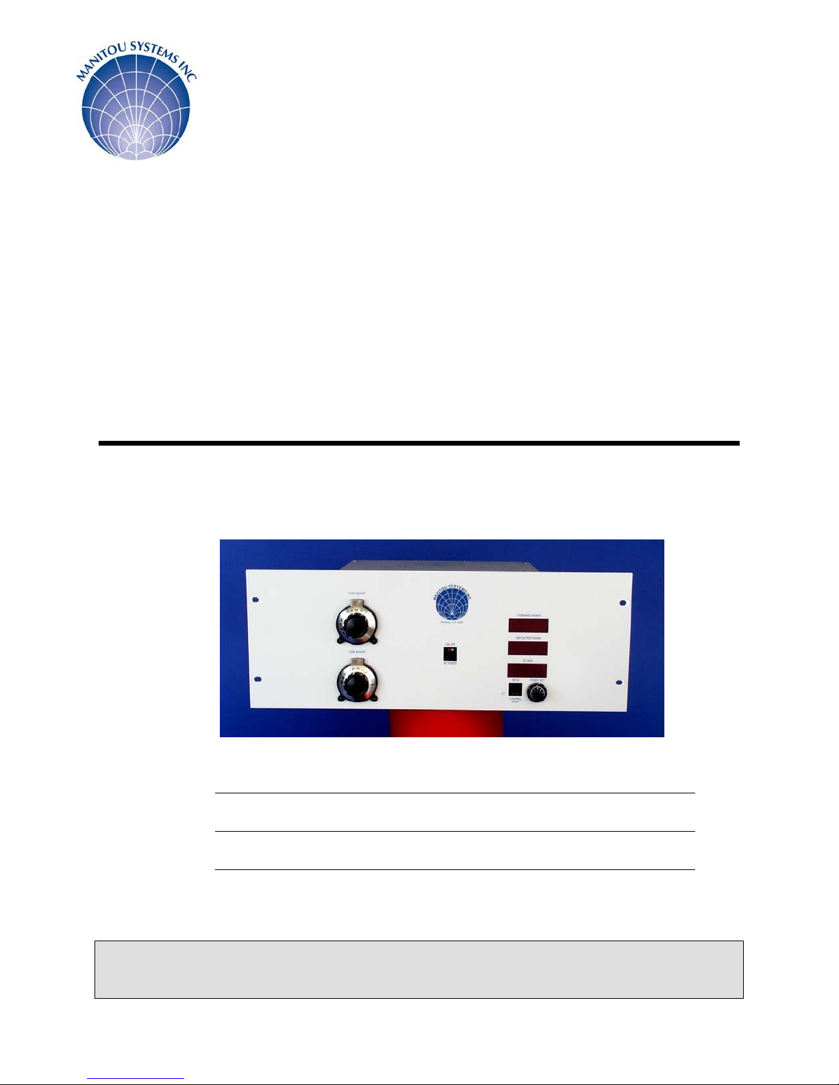
SERIES PB-3
13.56 MHz RF POWER SYSTEM
OWNERS
MANUAL
OWNERS MANUAL
CUSTOMER
DATE
SERIAL #
COPYRIGHT MANITOU SYSTEMS, INC. 2002 Part # 00800077 r-1 File # PB3 manual- 100_300W digital MSI
Web: www.manitousys.com Email: info@manitousys.com
Manitou Systems, Inc.
12 South Street Danbury, CT 06810
Office Tel.203.792.8797 Fax.203.792.7097
Page 2

SERIES PB-3 13.56 MHz RF Power System
WARNING
Lethal RF and DC voltages are present in this system.
Only qualified personnel should install and service this equipment.
Prior to installation and operation of this system, this instruction manual should be consulted to ensure that
the installation and operation are in accordance with Manitou Systems' recommendations.
Failure to properly install or operate this unit will result in voiding the equipment warranty.
Copyright 2002 Manitou Systems, Inc.
This owner’s manual is provided to enable the user to safely install, operate and service the equipment
described.
Manitou Systems, Inc. reserves the right to make product changes and enhancements without notification
or obligation.
For more information, please write Manitou Systems, Inc. 12 South Street Danbury, CT 06810 USA or
contact us via:
• Telephone at (203) 792-8797
• FAX at (203) 792-7097
• e-mail info@manitousys.com
• Website at www.manitousys.com.
Published in the United States of America.
This document may not be reproduced without the written permission of Manitou Systems, Inc.
All rights reserved.
Revisions to Manual
12.8.02 SMS r1- Add new ground/return scheme to User I/O connection. Modified Section 2.4 Pg 11 &
Section 32. Pg 14
High-powered solutions for RF and microwave applications
Corporate Headquarters: 2
12 South Street Danbury, CT 06810
Tel: 203-792-8797 Fax: 203-792-7097
Email: info@manitousys.com
www.manitousys.com
Page 3

SERIES PB-3 13.56 MHz RF Power System
TABLE OF CONTENTS
SECTION 1 INTRODUCTION
1.1 General Description
1.2 Icon Explanations
1.3 Mechanical Description
1.4 Technical Specifications
1.5 Safety Precautions
1.6 Theory of Operation
SECTION 2 INSTALLATION
2.1 Unpacking Your PB-3
2.2 System Components List
2.3 Mechanical Installation
2.4 Electrical Installation
SECTION 3 OPERATION
3.1 Front Panel / Operator Controls & Metering
3.2 Rear Panel Controls & Connections
3.3 Preliminary Operator Control Settings
3.4 Preliminary Checks Before Turning on the RF Power
3.5 Turning on the RF Power
SECTION 4 TROUBLESHOOTING PROCEDURES
4.1 RF Generator Problems
4.2 Impedance Matching Network Problems
SECTION 5 MAINTENANCE PROCEDURES
5.1 Cleaning Of Debris
5.2 Front Panel Cleaning
SUPPLEMENTS
PB3 Common Exciter operation tech note.
High-powered solutions for RF and microwave applications
Corporate Headquarters: 3
12 South Street Danbury, CT 06810
Tel: 203-792-8797 Fax: 203-792-7097
Email: Sales@manitousys.com
www.manitousys.com
Page 4

SERIES PB-3 13.56 MHz RF Power System
INTRODUCTION SECTION 1
1.1 GENERAL DESCRIPTION
1.2 ICON EXPLANATIONS
1.3 MECHANICAL DESCRIPTION
1.4 TECHNICAL SPECIFICATIONS
1.5 SAFETY PRECAUTIONS
1.6 THEORY OF OPERATION
1.1 GENERAL DESCRIPTION
The budget minded SERIES PB-3 is specifically designed for continuous operation in gas plasma
process applications.
The RF power generator and manual impedance matching network are both housed in a single,
compact enclosure.
The RF generator provides precise process control - even in the varying environment of plasma
processes. Ruggedized output transistors are used to ensure reliability during 100% duty-cycle
operation. A high current switch mode DC power module provides all necessary support power.
The system's control circuitry offers fine control resolution: A ten (10) turn control pot is used to
provide a 1% control resolution.
A manually controlled impedance matching network provides the user with a broad tuning range.
The network includes a tapped, field changeable series inductor and optional fixed shunt
capacitor(s) enabling the unit to match a wide range of plasma electrode impedances.
An optional common exciter input allows the PB-3 to be used in multiple cathode and substrate
bias applications.
External analog user interface connections permit the PB-3 to be controlled via the user's PLC or
computer.
High-powered solutions for RF and microwave applications
Corporate Headquarters: 4
12 South Street Danbury, CT 06810
Tel: 203-792-8797 Fax: 203-792-7097
Email: Sales@manitousys.com
www.manitousys.com
Page 5

SERIES PB-3 13.56 MHz RF Power System
1.2 ICON EXPLANATIONS
This symbol is used only where an immediate hazard exists.
WARNING
CAUTION
When this word is used, immediate danger exists and special
precautions are necessary to prevent possible injury, death or
significant property damage.
This symbol is used when unsafe operating or service
practices could result in damage to the equipment
This icon means "NOTE" or the information following should be
mentally highlighted.
The finger-pointing icon is used to indicate a procedure or step
required before powering on the system.
1.3 MECHANICAL DESCRIPTION
The system's chassis footprint measures 12" W x 7" H x 16" D, the chassis is attached to a 19"
wide rack mount front panel. The cabinet is constructed from chemically treated aluminum
components. The front panel and top cover are removable to provide access to system
components and adjustments.
The PB-3 is designed to be mounted in a 19” electronics rack cabinet.
Cooling air is drawn in through the rear panel inlets and exhausted through a side panel louver.
All operator controls are mounted on the front panel.
AC mains input, RF power output, common exciter in/out and a remote control connector are
grouped together on the rear panel.
The internal matching network is connected to the generator’s output by a short coaxial cable
(terminated with a BNC male connector) that protrudes from the rear of the unit. The matching
network may be bypassed by disconnecting this short cable from the generator’s output and
connecting the load in its place.
High-powered solutions for RF and microwave applications
Corporate Headquarters: 5
12 South Street Danbury, CT 06810
Tel: 203-792-8797 Fax: 203-792-7097
Email: Sales@manitousys.com
www.manitousys.com
Page 6

SERIES PB-3 13.56 MHz RF Power System
1.4 TECHNICAL SPECIFICATIONS: SYSTEM LEVEL
Input Power PB3/100 110 VAC, 50/60 Hz, 1 Phase, 5A Max
PB3/100 220 VAC, 50/60 Hz, 1 Phase, 2.5A Max
PB3/300 220 VAC, 50/60 Hz, 1 Phase, 5A Max
Cooling Forced air via a 110-CFM fan. Maximum 90% relative humidity &
degrees F ambient temperature.
100
System Footprint 12-1/4" W x 6" H x 16" D with a 7" high, 19" rack mount front panel.
Shipping Weight Approximately 25 lbs.
RF Output Power 100 or 300 watts into a 50 ohm load
Output Frequency 13.56 MHz +/- .005%
Output Impedance 50 ohms resistive
Output Connector BNC female
Output Power Stability +/- .5% of set-point
TECHNICAL SPECIFICATIONS: IMPEDANCE MATCHING NETWORK
RF Output Connection HN female coaxial cable connector
RF Input Connector BNC male coaxial cable connector
Matching Network "L" using a variable shunt capacitor and a tapped series inductor &
variable capacitor. Additional fixed shunt capacitors are installed in the
network, these may be connected in parallel with the variable shunt
capacitor if needed to match low impedance loads.
Matching Network Shunt Capacitor: 1000 pF
Element Values Series Capacitor: 488 pF
Series Inductor: 2.5 uH
Shunt Cap (Fixed) 200 & 400pF
Output Impedance Wide range - will match to all sputtering sources and
plasma etching / deposition electrodes
1.5 SAFETY PRECAUTIONS
High-powered solutions for RF and microwave applications
Corporate Headquarters: 6
12 South Street Danbury, CT 06810
Tel: 203-792-8797 Fax: 203-792-7097
Email: Sales@manitousys.com
www.manitousys.com
Page 7

SERIES PB-3 13.56 MHz RF Power System
SAFE OPERATION IS THE RESPONSIBILITY OF THE USING ORGANIZATION AND ITS
PERSONNEL. READ THIS OWNERS MANUAL AND UNDERSTAND HOW TO AVOID
HAZARDS PRIOR TO OPERATING THIS UNIT.
Your compliance with the following safety practices is expected:
1. Never work alone on live electrical circuits. You must be within sight or calling distance of
another employee who has the following qualifications:
A. Knows how to remove power from the equipment.
B. Knows how to apply artificial respiration.
C. Is acquainted with emergency procedures, first aid locations and the use of fire
extinguishers.
2. Do not wear rings, wristwatches or other jewelry on your person while working on live electrical
circuits.
3. Wear eye protection while working on live electrical circuitry where a flash might occur.
DO NOT WEAR CONTACT LENSES.
Because currents of 40 ma or greater across the chest can be fatal, read this manual to find out,
before working on the equipment, how much current is present in each circuit.
BE EXTRA CAREFUL!
4. Replace all safety shields after completing system setup, trouble shooting and maintenance
procedures.
5. Immediately report to your supervisor any unsafe conditions that exist.
WARNING Proper use and safe operating practices with respect to this system are
the responsibility of the user of this system. Manitou Systems, Inc. provides information on its
products and associated hazards, but it assumes no responsibility for the after-sale operation and
safety practices; take appropriate action to protect personnel and property from hardware failure.
All personnel who work with or are exposed to this system must take precautions to protect
themselves against possible serious and/or fatal bodily injury. DO NOT be careless around this
system.
High-powered solutions for RF and microwave applications
Corporate Headquarters: 7
12 South Street Danbury, CT 06810
Tel: 203-792-8797 Fax: 203-792-7097
Email: Sales@manitousys.com
www.manitousys.com
Page 8

SERIES PB-3 13.56 MHz RF Power System
1.6 THEORY OF OPERATION
The Series PB-3 is a fixed frequency plasma power system consisting of an RF generator and a
manual impedance matching network.
RF GENERATOR
The RF generator is comprised of a DC power section, operator/control panel, switch mode RF
power generator module and an RF power detector module.
Switch Mode RF Power Generator Module
The operating frequency (13.56 MHz) is fixed using a crystal oscillator. Its output drives a TTL
integrated circuit, which produces a square wave output that is fed directly to the gates of a class
C FET RF power amplifier.
This ruggedized power amplifier produces an RF output of 100 or 300 watts maximum based on
the model. The entire circuit is air-cooled.
DC Power Section
The DC power section supplies all of the necessary DC power to the front panel/control board and
the RF section. A fused, switched power entry module is provided on the PB-3 rear panel to
protect the entire system. A fuse is present on the control power supply board for its own
protection.
Operator/Control Panel
The operator/control board contains the basic controls, circuits and switches required to preset,
control, and monitor the PB-3's forward and reflected RF output power. The adjustment knobs for
the impedance matching network are also included on this panel.
The front panel circuit board also includes circuits designed to provide linearization, RF control,
metering and user interface functions. It first linearizes the forward and reflected RF power
signals coming from the RF detector module. This circuit also provides protection for the RF
power amplifier module and its transistors in the event of a mismatched plasma load (i.e. highreflected power or an over current condition). The DC drive signal and subsequent RF output
level is limited under these fault conditions. The user interface section of the module contains a
provision for programming the RF power set point input signal. This input can be switched
between Local and Remote by connections on the 25 pin interface connector. Local is defined as
control via the operator/control panel. Remote is defined as operation from a customer's external
signal. All outputs are available at the DB-25 connector in either local or remote control mode. All
signals are buffered by op-amp devices. The interface shorting plug shipped with the unit is
configured to permit local (front panel) control of the RF output level.
High-powered solutions for RF and microwave applications
Corporate Headquarters: 8
12 South Street Danbury, CT 06810
Tel: 203-792-8797 Fax: 203-792-7097
Email: Sales@manitousys.com
www.manitousys.com
Page 9

SERIES PB-3 13.56 MHz RF Power System
1.6 THEORY OF OPERATION
RF Power Detector
The power detector is used to provide the control circuits with DC signals corresponding to the
forward and reflected power detected at the generator's output.
Matching Network
The manual impedance matching network uses an "L" circuit topology. A variable shunt capacitor
and a tapped fixed series inductor & variable capacitor are used to match the RF generator's 50
ohm resistive output to the complex plasma impedance. Additional fixed shunt capacitors (200 &
400pF) are included in the unit and may be connected if needed to match low impedance loads.
As delivered, this network exhibits a wide range output impedance and will match to most
sputtering sources and plasma etching / deposition electrodes
Interlocks
When the external interlock connection is satisfied, the green LED on the RF power on/off switch
will illuminate indicating the unit is in a standby condition.
The over temperature interlock is controlled by a thermostat located on the RF generator's heat
sink surface. If an over temperature condition exists, this thermostat will break the RF power set
point circuit. There are no operator indicators connected to this circuit. The PB-3's front panel
indicators will appear normal, but NO output power will be available. The user should wait until
the system cools down, check for cooling vent obstructions & fan operation and re-start the
system.
INSTALLATION SECTION 2
2.1 UNPACKING THE PB-3
2.2 SYSTEM COMPONENTS LIST
2.3 MECHANICAL INSTALLATION
2.4 ELECTRICAL INSTALLATION
2.1 UNPACKING
Remove the unit from its packing and shipping material. Inspect for any damage and contact
Manitou Systems Inc. and the shipping company if any is found.
High-powered solutions for RF and microwave applications
Corporate Headquarters: 9
12 South Street Danbury, CT 06810
Tel: 203-792-8797 Fax: 203-792-7097
Email: Sales@manitousys.com
www.manitousys.com
Page 10

SERIES PB-3 13.56 MHz RF Power System
2.2 SYSTEM COMPONENTS LIST
A. PB-3 System
B. DB-25 User Interface Connector with Hood
C. Owners Manual
2.3 MECHANICAL INSTALLATION
The Model PB-3 RF power system is designed to mount near the vacuum chamber RF feedthrough in a standard 19" rack. It requires 7" of height in the rack. Alternately, it may be fastened
to the system chassis using the four (4) 10-32 mounting holes in the baseplate.
Connect the BNC Male “Pigtail Coax” (Matching Network Input) to the female BNC
connector (RF Generator Output).
Always provide continuous airflow through any enclosed electronics rack cabinet containing
heat generating equipment. Exhaust fans mounted in the cabinet's top surface and a filtered inlet
at the bottom will provide the correct enclosure cooling.
2.4 ELECTRICAL INSTALLATION
WARNING
normal system operation.
1. The high voltage in this system can cause instant electrocution upon contact or, under some
circumstances, even close proximity to contact. Except as specified in this manual, never open
the system covers or panels without disconnecting the AC input power at its wall source and also
attaching a grounding rod to the high voltage circuit.
2. The system's radio frequency power is transferred to the vacuum chamber through a shielded
vacuum feed through. Harmonic RF energy generated in the plasma discharge and will radiate if
the vacuum chamber is not well grounded. Install a low impedance ground strap between the
chamber and PB-3 and earth ground. This strap should be constructed from silver plated copper
sheet. The width should be 1" to 2" wide X .020" thick. Keep these connections as short as
possible.
3. Before operating the power supply for the first time, it is essential to insure that ground
connections have been installed as specified, that all interlocks are verified to be working properly
and that all high voltage and RF carrying conductors are shielded from human contact. Every
precaution must be taken to install and operate the system in accordance with this manual.
4. In a faulty circuit, operational voltages can be retained internally even after the source of the
power is shut off. Always insure that all filter capacitors are discharged after disconnecting source
power and before examination. Don't assume the power is off until it is checked.
5. If you must examine the system or its AC source with the power on, have another person
present, use the schematics, lock out any power that is not needed, and attach test meter leads
before turning the power on. NEVER, UNDER ANY CIRCUMSTANCES, REACH INSIDE THE
POWER SUPPLY WITH THE POWER ON.
Please review the following initial checkout procedure. Follow these steps prior to
High-powered solutions for RF and microwave applications
Corporate Headquarters: 10
12 South Street Danbury, CT 06810
Tel: 203-792-8797 Fax: 203-792-7097
Email: Sales@manitousys.com
www.manitousys.com
Page 11

SERIES PB-3 13.56 MHz RF Power System
CONNECTING THE PB-3
The following installation steps will help the user understand how to connect the PB-3 to a plasma
processing system.
1. The PB-3 is connected to an AC power source, 115 VAC or 220 VAC, 50/60 Hz via its three (3)
conductor (grounded) cord. This power source should be capable of supplying at least 5 amps.
2. A solid copper ground strap is used to connect the enclosure to the chamber and system
ground point. Refer to "Rear Panel" drawing for details.
3. The output of the impedance matching network is connected to the electrode using a coaxial
cable.
4. Dress all RF carrying cables away from all other control and sensor cables.
5. All remote connections are made via the DB-25 connector on the back of the enclosure. Use a
shielded cable for these connections. Refer to the following list and to "Remote / User PB-3
Connections" drawing for details. The factory supplied shorting plug must be installed
for proper operation if no external control functions are to be utilized.
Connections to 25 pin d-sub connector on rear of generator:
Pin: Function:
1 Ground/common for external interlock & Remote RF ON/OFF
2 External interlock- tie to pin 1 to enable.
3 External Setpoint In (0 to 5 Vdc)- reference to pins 17/18.
6 Remote RF on- Tie to pin 1 for normal operation, switch to enable remote on/off.
7 Forward Power Out signal (0 to 5 Vdc representing 0-100% power)- reference to
pins 17/18.
9 Reflected Power Out signal (0 to 5 Vdc representing 0-100% reflected power)-
reference to pins 17/18.
14 External Setpoint input select—tie to pin 16 to select external setpoint.
15 Front Panel Setpoint select—tie to pin 16 to select front panel control.
16 Drive signal select- connect to pin 14 or 15 to select remote or local setpoint
control. Note: do not connect to pins 14 and 15 simultaneously.
17&18 Ground/common for all external 0 to 5 Vdc I/O signals
23 DC Bias out signal (optional) (0 to 5 Vdc = 0 to 1000V of bias)- reference to pins
17/18.
The external interlock must be satisfied before using the system. Connect an external interlock
switch to user interface connector between pins 1 & 2. Contact closure is necessary to satisfy the
interlock.
0 to +5VDC output signals are present at the interface connector for the Forward & Reflected RF
output power, and DC bias (optional). (0 to 5V represents 0-100% of the value) These signals
are referenced to pins 17 & 18 on the interface connector.
A 0 to +5VDC input signal is required for remote control of the forward power or DC bias preset if
High-powered solutions for RF and microwave applications
Corporate Headquarters: 11
12 South Street Danbury, CT 06810
Tel: 203-792-8797 Fax: 203-792-7097
Email: Sales@manitousys.com
www.manitousys.com
Page 12

SERIES PB-3 13.56 MHz RF Power System
r
external control is to be used. This signal is referenced to pins 17 & 18 on the interface
connector.
A continuous contact closure is required to control the RF on/off function. This switch is connected
to the user interface connector between pins 1 & 6. These pins should be jumped to enable
operation of the front panel mounted RF ON/OFF switch. The front panel mounted RF ON/OFF
switch must be set in the "ON" position (pushed in) when using a remote switch. The interface
plug as shipped has this connection made, allowing use of the front panel switch without further
wiring being needed.
A contact closure between either pins 15 and 16 (local control; power or DC bias is varied by
adjusting the front panel potentiometer) or pins 14 and 16 (external control; power or DC bias is
varied by a 0 to 5V signal between pins 3 [+] and 1 [gnd]) is required for generator operation. The
interface plug as shipped is configured for local operation, allowing use of the front panel setpoint
control without further wiring being needed
OPERATION SECTION 3
3.1 FRONT PANEL / OPERATOR CONTROLS & METERING
3.2 REAR PANEL CONTROLS & CONNECTIONS
3.3 PRELIMINARY OPERATOR CONTROL SETTINGS
3.4 PRELIMINARY CHECKS BEFORE TURNING ON THE RF POWER
3.5 TURNING ON THE RF POWER
3.1 OPERATOR CONTROLS & METERING
Tune
RF
On/Off
Switch
Load
Adjust
Knob
RF Power Output On/Off: Pressing this switch turns the RF power output "ON". Pressing it
again turns the RF power "OFF". The red LED indicates "RF ON" and the green LED indicates
that the interlock loop status. When the external interlock is satisfied, the green LED will
illuminate.
Forward & Reflected Power and DC BIAS Digital Meters: These meters display Forward &
Reflected RF Power, and the DC Bias developed on the load. The forward RF output power (100
Forward Power
Meter
Reflected Power
Meter
DC Bias Mete
Setpoint
Control Knob
Control Mode
Switch
High-powered solutions for RF and microwave applications
Corporate Headquarters: 12
12 South Street Danbury, CT 06810
Tel: 203-792-8797 Fax: 203-792-7097
Email: Sales@manitousys.com
www.manitousys.com
Page 13

SERIES PB-3 13.56 MHz RF Power System
A
or 300 watts full scale) is displayed on the top meter, the reflected power (30W full scale) is
displayed on the center meter, and the DC Bias (1kV full scale) is displayed on the bottom meter.
Setpoint Control Knob: This ten (10) turn control pot enables the operator to set and vary the
Forward RF Power output or DC Bias.
Control Mode Switch: This alternate-action switch selects the control mode of the generator. In
the RF position, the setpoint (either from the front panel or the remote input) controls the forward
RF power. In the DC Bias position, the setpoint controls the DC Bias developed on the load
(within the limits of available power from the generator).
Load & Tune Adjust Knobs: These knobs are used to adjust the position of the tuning
capacitors in the matching network. Turning the knob clockwise increases the capacitor setting,
turning it counterclockwise decreases it. The knobs are vernier drive to allow for finer tuning, and
have reference scales calibrated from 0-100.
3.2 REAR PANEL CONTROLS & CONNECTIONS
Common Exciter Input
Interface Connection
Common Exciter Output
Cooling Air Intake
Fuseholder
Power Swich
C Mains Connection
PB3 Rear Panel
Power Entry Module: This component, located in the lower left corner of the generator (as
viewed from the rear) contains the line fuses, line filter, main power switch and detachable power
cord. The fuse(s) are accessed by removing the power cord and opening the protective door,
then removing the red fuse carrier. The fuse value is noted on the red carrier. 120V units are
single-fused, 208V units are double fused. All fuses are slow-blow types. The main power switch
is located in the middle of the powerline entry module, 0 is off and 1 is on. The detachable power
cord in connected to the IEC320 receptacle at the bottom of the module.
Interface Connector: A DB-25 female connector is provided for interfacing the supply's various
Inputs and Outputs to a user's process controller.
• Pin 1 Common/ground for external interlock and RF ON/OFF switches
• Pin 2 External Interlock connection (connect to pin 1 to operate generator)
• Pin 3 External 0 to +5 VDC setpoint input
• Pin 6 External RF ON/OFF (connect to pin 1 to operate generator)
• Pin 7 External Forward Power signal 0 to +5 VDC (0 to full power)
• Pin 9 External Reflected Power signal 0 to +5 VDC (0 to 30 watts)
High-powered solutions for RF and microwave applications
Corporate Headquarters: 13
12 South Street Danbury, CT 06810
Tel: 203-792-8797 Fax: 203-792-7097
Email: Sales@manitousys.com
www.manitousys.com
RF Output
Matchnet Input (Pigtail,
shown connected to RF
Matchnet Output
Cooling Air Intake
Ground Stud
Page 14

SERIES PB-3 13.56 MHz RF Power System
• Pin 14 Remote Control Select (connect to pin 16 to enable remote setpoint
control)
• Pin 15 Local Control Select (connect to pin 16 to enable local [front panel]
setpoint control)
• Pin 16 Control Select Common
• Pins 17&18 Common/grounds for all 0 to 5 VDC I/O signals
• Pin 23 External DC Bias signal 0 to +5 VDC (0 to 1kV bias)
Common Exciter I/O: Two BNC jacks located next to the Interface Connector are provided to
permit two or more PB-3's to operate in synchronization for applications requiring multiple plasma
sources in a single chamber. (For further information regarding the use of multiple generators in a
single chamber, see the application note at the end of this manual.)
RF OUTPUT: The RF Output connector is a BNC jack located just above and to the right of the
center of the rear panel of the generator. It is connected to the output of the VSWR board inside
the generator, and allows the RF output to be directly accessed without the match network
intervening. It is intended to be connected to a 50 ohm resistive load.
MATCHNET INPUT: The matchnet input connection is a short pigtail terminated in a male BNC
connector. For normal operation, it is connected to the RF OUTPUT jack mentioned above. The
pigtail connects to a quarter-wave cable coiled inside the cabinet in the matching network
compartment, the distal end of which is connected to the input side of the matching network.
MATCHNET OUTPUT: The matchnet output is a female HN connector located on the upper right
side of the rear panel of the generator. It connects to the output side of the internal matching
network, and is to be connected to the load via a heavy-duty coaxial cable. The connection
between the matchnet output and the plasma load should be kept as short as possible.
3.3 PRELIMINARY OPERATOR CONTROL SETTINGS
Prior to turning on the AC Main Power and RF Output Power in an unknown load situation, we
recommend presetting the controls as follows (once preliminary operating parameters such as a
known plasma ignition point and power level have been determined, those settings may be used
for startup):
A. Power Set pot to 0.00
B. Mains switch (rear panel) turned off.
Ensure that the matching network output is connected to the vacuum chamber's RF feedthrough, the matching network input is connected to the generator output and that the common
exciter I/O's are connected.
High-powered solutions for RF and microwave applications
Corporate Headquarters: 14
12 South Street Danbury, CT 06810
Tel: 203-792-8797 Fax: 203-792-7097
Email: Sales@manitousys.com
www.manitousys.com
Page 15

SERIES PB-3 13.56 MHz RF Power System
3.4 PRELIMINARY CHECKS BEFORE TURNING ON THE RF POWER
Prior to turning the RF Power On, preset and stabilize all process parameters such as vacuum
chamber pressure and process gas flow.
Turn on all cooling water channels (to electrode or cathode).
Ensure that all RF connections and system grounds are tight. Turn on the Main Power Switch.
Allow at least 5 minutes of warm-up and stabilization time for the PB-3.
Check to see that all interlocks have been satisfied. The RF power cannot be turned on in an
unsatisfied condition.
Check to see that the green LED (located on the RF Power switch) is lit. This indicates that the
system interlocks are satisfied and it is in the ready state.
If this LED is not lit, check the external interlock devices or connections.
3.5 TURNING THE RF ON
Preset the impedance matching network capacitor positions a known plasma ignition point or to
50%.
Press the RF Power switch to turn the RF output ON. The red LED indicator will light to indicate
this state.
Turn the Power Set control clockwise 1-2 turns and check to see that the forward power meter
indicates that a small amount of FORWARD RF power is being delivered to the load.
Adjust the TUNE capacitor for a small peak in the indicated FORWARD power. This peak
indicates the plasma strike point. (Plasma ignition can be confirmed by the indication of bias on
the DC Bias display.)
At this time, adjust the LOAD capacitor position to obtain a null in the REFLECTED power.
The operator will now be able to view an active glow discharge in the vacuum chamber.
Adjust the power level to the desired value while continuing through a number of TUNE & LOAD
control iterations until a minimum Reflected Power reading is achieved. If the plasma
extinguishes, the generator may need to be re-started (using the RF ON switch), but plasma can
usually be reestablished by detuning slightly.
The PB-3 will protect itself during a miss-match by folding back the forward power to a safe level.
The operator will notice that a glow discharge can be ignited and the tune & load controls adjusted
for maximum preset forward power. The matching network will then need to be tweaked for
minimum reflected power.
High-powered solutions for RF and microwave applications
Corporate Headquarters: 15
12 South Street Danbury, CT 06810
Tel: 203-792-8797 Fax: 203-792-7097
Email: Sales@manitousys.com
www.manitousys.com
Page 16

SERIES PB-3 13.56 MHz RF Power System
4.1 RF GENERATOR PROBLEMS
4.2 IMPEDANCE MATCHING NETWORK/TUNING PROBLEMS
4.1 RF GENERATOR PROBLEMS
TROUBLESHOOTING PROCEDURES SECTION 4
• If the cooling fan does not start check the AC mains circuit. Is it operational? Is the PB3
power cord inserted properly into the rear panel connector? Is the AC Mains switch turned
on? If all of the answers are yes, the problem may be a blown fuse on the control power
supply. This fuse may be replaced removing the top cover and looking for the fuse on the top
surface under the ribbon cables.
• If the cooling fan is running and the green LED indicator does not light, there is a possibility
that the external interlock connection is not closed. Please check that the DB25 connector on
the rear panel is correctly inserted and the connections are per the drawing.
• If the red LED does not light, the problem may be in the external interface connector. The
contacts must be jumped (just like the external interlock contacts) to enable the RF to start.
Please consult the drawing for correct connections.
RF Power Module Location
PB3 Chassis top view
Series Capacitor Location
Shunt Capacitor Location
(Below Inductor)
• If there is no indication of Forward RF power (with the red LED lit) there is a possibility that the
generator’s temperature overload thermostat has tripped. Please look for the possibility that
the cooling fan is not operational or that one of the cooling air openings is blocked.
4.2 IMPEDANCE MATCHING NETWORK/TUNING PROBLEMS
The PB3 impedance matching network incorporates two variable capacitors and a fixed (tapped)
inductor to enable matching to all types of plasma loads including small sputtering guns and
High-powered solutions for RF and microwave applications
Corporate Headquarters: 16
12 South Street Danbury, CT 06810
Tel: 203-792-8797 Fax: 203-792-7097
Email: Sales@manitousys.com
www.manitousys.com
Control Power Supply Fuse Location
Front Panel Location
Page 17

SERIES PB-3 13.56 MHz RF Power System
substrate bias stages. Although the factory pre-sets and tests the system using a 3” magnetron
sputtering gun, the user may need to adjust the network to operate with their particular process
load.
It should also be noted that the PB3 is designed to mount close to the plasma source and utilize a
coaxial cable not longer than 6’ in length. (Manitou Systems offers high current Teflon based
cables in various lengths and with various connector styles to complement the user’s application.
(Please consult the factory for availability.)
The typical cable furnished is an RG-393 cable with an HN male connector mounted on the PB3
side and either an HN or N connector on the user’s side to connect to the plasma load. Other
cable types may be used; however we caution against using polyethylene or foam insulated
cables as there are high RF circulating currents which may cause melting and degradation of the
insulator over time. The result is an unstable match with the possibility of a short circuit. Please
consult the factory if your application requires the use of a longer cable.
Please follow the following procedures if the tuner will not match to the load (achieve minimum reflected
power):
• Does the plasma ignite? If so, is the tuner unable to reach a null in the reflected
power? The series inductor in the tuner module may need to be adjusted. Remove
the top cover and change the tap setting and repeat the tuning process.
The rule of thumb for the inductor position is maximum inductance for a small cathode
surface area and minimum inductance for a large area cathode surface area. If the
inductance is too low, the TUNE (or series) capacitor will try to tune towards 100%. If
the inductance is to high, the tune capacitor will tune towards 0%.
• If the plasma lights and the network’s LOAD capacitor adjusts for minimum reflected
power at the high end of its range, there may be the need for additional shunt
capacitance. This is accomplished by adding a fixed high current (doorknob) type
capacitor in parallel with the larger variable capacitor. Please consult the factory for
availability of the kit.
Another rule of thumb is that the load capacitor will need to be increased if an output
cable longer that 6 feet is used to connect the plasma load. This is because the load
capacitor is trying to tune out the fixed capacitance of the coax cable.
In some applications it may be possible to tune into a long output cable with a low
reflected power and NO plasma ignition.
• If there is no plasma ignition, check to see if all chamber parameters are OK. These
may include the presence of process gas, proper vacuum pressure (or vacuum level ~
3-4 microns), proper shutter position as a shutter that is too close to the target surface
may not allow gas flow to the target surface.
• A verification of the plasma load may include a quick continuity check across the input
connector to see if there is an internal short circuit. The measurement in ohms should
be very high (Meg ohms). If it is low (ohms) there may be a metal flake across the
dark space shield to the target surface.
High-powered solutions for RF and microwave applications
Corporate Headquarters: 17
12 South Street Danbury, CT 06810
Tel: 203-792-8797 Fax: 203-792-7097
Email: Sales@manitousys.com
www.manitousys.com
Page 18

SERIES PB-3 13.56 MHz RF Power System
Tap #4 – Least Inductance
Tap #3 – Medium Inductance
Tap #2 – Medium Inductance
Tap #1 – Most Inductance
MAINTENANCE PROCEDURES SECTION 5
5.1 CLEANING OF DEBRIS
5.2 FRONT PANEL CLEANING
5.1 CLEANING OF DEBRIS
After continued use, the PB-3 will build up dust and debris around the air intake and exhaust
positions.
Use a vacuum cleaner with a soft brush attachment to gently remove the dust build up from these
areas.
If the PB-3 is used in a very dusty location, the top cover may be removed to facilitate the cleaning
of the interior components. Use compressed air (less than 20 psi) to blow out the dust.
5.2 FRONT PANEL CLEANING
The plastic front panel overlay may be cleaned using a mild detergent mixture (dish washing liquid
is acceptable). Gently wipe the surface and switch operators with a dampened cloth to remove dirt
and finger oil buildup. Under NO circumstances use any solvents as these chemicals will destroy
the plastic surfaces.
PB3 Matching Network Section
Inductor Tap Selection
High-powered solutions for RF and microwave applications
Corporate Headquarters: 18
12 South Street Danbury, CT 06810
Tel: 203-792-8797 Fax: 203-792-7097
Email: Sales@manitousys.com
www.manitousys.com
 Loading...