

Page 1

CATALOG 648395
R04--07
MANITOU NORTH AMERICA, INC.
6401 IMPERIAL DRIVE
Waco, TX 76712--6803
NOTE: Manitou Forklift Manuals are continually updated and subject to change
without prior notice. If your Forklift Model or parts are not found in this manual,
please contact your dealer or the Manitou North America Parts Department
for the latest information and parts availability.
MRT2150
PRIVILEGE E3
CRANE OPERATION
MANUAL
For Parts Orders contact your Manitou North America Dealer or call:
Manitou North America, Parts Dept. 800--425--3727 or (254) 799--0232
Parts Dept. Fax: (254) 867--6504 Website: www.manitou--na.com
Page 2

Page 3

04/2007 REF : 648395 (IT-EN-DE)
MMMMRRRRTTTT 1111888855550000 ---- 2222111155550000 --
--
22225555444400
00
- E3 -
MANUALE DI UTILIZZO GRU
CRANE OPERATION MANUAL
BETRIEBSANLEITUNG KRAN
IL VOSTRO CONCESSIONARIO :
YOUR DEALER:
IHR VERTRAGSHÄNDLER:
COSTRUZIONI INDUSTRIALI
Via Cristoforo Colombo, 2
Loc. CAVAZZONA
41013 Castelfranco Emilia (MO)
Tel. 059/959811 - Fax 059/959850
Page 4

2
IT
EN
DE
5
MRT 1850 - 2150 - 2540
1
st
DATE PUBLICATION
04/2007
04/2007
Catalogue information:
Date publication:
Text and illustrations herewith enclosed
may not be reproduced, not even in part
and by any means.
Because of the possible time lag beween
the introduction of technical modifications
(an on-going process the aim of which
is to offer products which are being
continually improved) and the latest up
date of the manual, we must point out,
for the sake of correctness, that the data
contained in this edition is liable to chan-
ge at any time and are therefore not
binding.
1
st
DATUM AUSGABE
04/2007
04/2007
Katalog auskunft:
Datum ausgarbe:
Die Reproduktion, auch nur teilweise, die-
ses Textes und der Abbidungen ist verboten.
Aus Gründen der Korrektheit muß darauf
hingewiesen werden, daS der
Zeitunterschied zwischen in Druck
befindlicher Naufassung und technischen
Veränderungen (die für ein Angebot von
immer basseren Geräten kontinuierlich
sind) zu Unterscheden in den Angaben
dieser Auflage Fühuren kann und daß die
darin enthaltenen Angaben underbindlinch
sind und jederzeit verändert werden kön-
nen.
1a DATA DI PUBBLICAZIONE
04/2007
04/2007
Informazioni catalogo:
Data di pubblicazione:
E’ vietata la riproduzione, anche parziale,
del testo e delle illustrazioni.
La differenza tra i tempi di aggiornamento
in stampa e i tempi delle modifiche tecni-
che (variando quast’ultime
continuamente, ciò al fine di offrire prodot-
ti sempre più qualificati) impongono di
dichiarare, per correttezza, che i dati
contenuti nella presente edizione sono
suscettibili di variazione in qualsiasi
momento e che quindi non sono
impegnativi.
Page 5

INTRODUCTION
THIS MANUAL PROVI-
DES SUPPLEMENTARY
INSTRUCTIONS IN ADDI-
TION TO THOSE
ALREADY GIVEN IN THE
MACHINE OPERATION
AND MAINTENANCE
MANUAL.
VORWORT
DIESES HANDBUCH
LIEFERT ZUSÄTZLICHE
ANWEISUNGEN,
MIT DENEN DIE
VERVOLLSTÄNDIGT
WERDEN, DIE SCHON IN
DER BETRIEBS- UND
WARTUNGSANLEITUNG
DER MASCHINE
STEHEN.
PREMESSA
QUESTO MANUALE
FORNISCE ISTRUZIONI
SUPPLEMENTARI CHE
INTEGRANO QUELLE
GIA’ FORNITE NEL
MANUALE DI USO E
MANUTENZIONE DELLA
MACCHINA.
3
IT
EN
DE
5
MRT 1850 - 2150 - 2540
Page 6
4
IT
EN
DE
5
MRT 1850 - 2150 - 2540
INTRODUCTION
-The manufacturer supplies a large
range of accessories (guarantees)
perfectly suitable for your fork lift
truck.
- The accessories are supplied
together with a load diagram regarding your fork lift truck. The instruction leaflet and load diagram must
remain in the lift truck. The use of
possible accessories depends on
the instructions given in this
manual.
- When the accessory mounted is
meant for lifting suspended loads
(such as jib with hook, winch, etc...)
your fork lift truck is automatically
classified as a crane truck.
Only accessories homologated and
certified as "CE" by the manufactu-
rer can be used on our fork lift
trucks. The manufacturer shall not
be responsible for unauthorized
modification or use of accessories.
Do not use interchangeable
accessories not originally inclu-
ded in the machine supply.
For subsequent requests for imple-
mentation of machine functions
using other accessories, before
starting up the machine, the user
must request inspection for suitabi-
lity for use by an authorized MANITOU technician, who will check the
correct working and updating of the
documentation necessary for using
the new accessory.
It is only after this inspection that a
new “CE” conformity certificate will
be issued for the machine indicating
only the new accessories installed.
All accessories with boom must be used
in the horizontal position
(see capacity diagram); for winches,
check the perfect verticality by means of
the pendulum indicator provided on the
accessory frame.
The machine equipped with accessory
with suspended load conforms to the following standards:
- DIN 15018-1, lifting unit
H1, stress unit B3
- DIN 15019-2
- EN 13000/2004, wind speed less
than 50km/h.
The winches are designed in accordance with standard
ISO 4301, as regards conditions of
use and equipment class: T4, L2, M4.
EINLEITUNG
- Der Hersteller stellt Ihnen (unter
Garantie) eine umfassende Palette von
Zubehörteilen für Ihren Stapler zur
Verfügung, die sich perfekt für diesen
eignen.
- Das Zubehör wird mit einem
Lastdiagramm zu Ihrem Stapler ausgeliefert. Die Betriebsanleitung und das
Lastdiagramm müssen im Stapler
bleiben. Der Gebrauch der möglichen
Zubehörteile wird durch die
Anweisungen geregelt, die in diesem
Handbuch stehen.
- Wenn das montierte Zubehörteil das
Heben hängender Lasten vorsieht (z.B.
Kranausleger mit Kranhaken, Winde
etc...) wird Ihr Stapler automatisch als
Fahrkran klassifiziert.
Nur zugelassene Zubehörteile mit "CE"
Kennzeichnung des Herstellers können
auf unseren Staplern benutzt werden.
Der Hersteller übernimmt keine Haftung,
wenn die Zubehörteile ohne sein Wissen
geändert und benutzt worden sind.
Die Benutzung ursprünglich nicht zur
Bestückung der Maschine vorgesehe-
ner austauschbarer Arbeitsgeräte ist
verboten.
Bei anschließenden Erfordernissen zur
Implementierung der
Maschinenfunktionen mit anderen
Arbeitsgeräten ist der Anwender vor der
Inbetriebnahme dazu verpflichtet, die
Kontrolle zur Gebrauchseignung seitens
eines autorisierten Technikers von
MANITOU zu beantragen, der den kor-
rekten Betrieb und die Aktualisierung der
zum Gebrauch erforderlichen
Dokumentation des neuen Arbeitsgeräts
prüfen wird.
Erst nach dieser Kontrolle wird eine
neue “EG” Konformitätsbescheinigung
der Maschine ausgestellt, auf der nur
die neu installierten Arbeitsgeräte
stehen.
Alle Zubehörteile mit Kranausleger müssen in der horizontalen Position benutzt
werden (siehe Lastdiagramme). Für die
Winden ist die perfekte Vertikalität mit-
tels des Pendelanzeigers auf dem
Gestell des Zubehörteils sicherzustellen.
Die Maschine, die mit Zubehörteil mit
hängenden Lasten ausgestattet ist, entspricht den folgenden Normen:
- DIN 15018-1, Hubklasse H1,
Beanspruchungsgruppe B3
- DIN 15019-2
- EN 13000/2004, Windgeschwindigkeit
unter 50 km/h
Die Winden sind gemäß der Norm ISO
4301 mit Einsatzbedingungen und
Klasse des Geräts geplant: T4, L2, M4.
INTRODUZIONE
- Il costruttore mette a vostra disposizione
(con garanzia) una vasta gamma di
accessori per il vostro carrello elevatore
e ad esso perfettamente adattati.
- Gli accessori sono consegnati con un
diagramma di carico relativo al vostro
carrello elevatore. Il libretto d’istruzioni
e il diagramma di carico dovranno
rimanere nel carrello elevatore. L’uso
dei possibili accessori é regolato dalle
istruzioni contenute nel presente
manuale.
- Quando l’accessorio montato prevede
il sollevamento di carichi sospesi
(es. jib con gancio, argano etc...) il
vostro carico elevatore viene classificato
automaticamente come gru mobile
Solo gli accesori omologati e certificati
“CE” dal costruttore sono utilizzabili sui
nostri carrelli elevatori. La responsabilità
del costruttore non sarà coinvolta in
caso di modifica o utilizzazione
di accessori effettuata a sua insaputa.
È vietato l’uso di accessori intercam-
biabili non previsti in origine in dota-
zione sulla macchina.
Nel caso di successive richieste di
implementazione delle funzioni della
macchina con altri accessori, l’utente
prima della messa in servizio ha l’obbli-
go di richiedere il controllo d’idoneità
all’impiego da parte di un tecnico auto-
rizzato MANITOU, che provvederà a
verificare il corretto funzionamento e
l’aggiornamento della documentazione
necessaria all’uso del nuovo accessorio.
Solamente dopo tale controllo verrà rila-
sciato un nuovo certificato di conformità
“CE” della macchina riportante unica-
mente i nuovi accessori installati.
Tutti gli accessori con braccio gru devono
essere utilizzati in posizione orizzontale (vedi
diagrammi di portata); per gli argani verificare
la perfetta verticalità tramite l’indicatore a
pendolo posto sul telaio dell’ accessorio.
La macchina equipaggiata di accessorio
con carico sospeso è conforme alle
seguenti norme:
- DIN 15018-1, gruppo di sollevamento
H1, gruppo di sollecitazione B3
- DIN 15019-2
- EN 13000/2004, velocità del vento
inferiore a 50Km/h.
Gli argani sono progettati secondo
la norma ISO 4301, con condizioni
di impiego e classe
dell’apparecchiatura: T4, L2, M4.
Page 7

Scala BEAUFORT
Velocità del vento ad una altezza di 10 m su terreno piatto
Grado
Tipo di
vento
Velocità
(nodi)
Velocità
(km/h)
Velocità
(m/s)
Effetti a
Terra
Effetti in
Mare
0 Calma 0 - 1
0 - 1 < 0.3
il fumo si alza verticalmente il mare è uno specchio
1
Bava di
vento
1 - 3
1 - 5 0.3 - 1.5
il vento piega il fumo
increspature corte ma più
evidenti
2
Brezza
leggera
4 - 6
6 - 11 1.6 - 3.3
Il vento è percepibile al volto;
agita le foglie
onde piccole ma evidenti
3
Brezza
tesa
7 - 10
12 - 19 3.4 - 5.4
Il vento agita continuamente
foglie e ramoscelli
piccole onde, creste che
cominciano ad infrangersi
4
Vento
moderato
11 - 16
20 - 28 5.5 - 7.9
il vento solleva polvere e pezzi
di carta; agita i ramoscelli
piccole onde più evidenti e
frequenti che diventano più
lunghe
5 Vento teso 17 - 21
29 - 38 8 - 10.7
gli arbusti con fogliame
ondeggiano
si formano piccole onde
nelle acque interne; onde
moderate allungate
6
Vento
fresco
22 - 27
39 - 49 10.8 - 13.8
Agita rami grossi;
i fili metallici sibilano; è
difficoltoso l’uso dell’ombrello
si formano onde con creste
di schiuma bianca, e spruzzi
7
Vento
forte
28 - 33
50 - 61 13.9 - 17.1
Agita interi alberi;
si ha difficoltà a camminare
contro vento
il mare è grosso, la schiuma
comincia ad essere
sfilacciata in scie.
8
Burrasca
moderata
34 - 40
62 - 74 17.2 - 20.7
Rompe rami di alberi;
è quasi impossibile camminare
contro vento
onde di altezza media e
maggiore lunghezza; dalle
creste si distaccano turbini di
spruzzi.
9
Burrasca
forte
41 - 47
75 - 88 20.8 - 24.4
Causa leggeri danni ai
fabbricati (camini, tegole ecc.).
grosse ondate, spesse scie
di schiuma e spruzzi,
sollevate dal vento, riducono
la visibilità
10 Tempesta 48 - 55
89 - 102 24.5 - 28.4
Raro all’ interno della terra
ferma; sradica alberi; causa
notevoli danni ai fabbricati
enormi e violente ondate con
lunghe creste a criniera;
visibilità ridotta
11
Tempesta
violenta
56 - 63
103 - 117 28.5 - 32.6
Molto raro, causa estese
devastazioni
onde enormi ed alte, che
possono nascondere navi di
media stazza; ridotta
visibilità
12 Uragano 64 +
oltre 118 32.7 +
Causa gravissime catastrofi
In mare banchi di schiuma;
l’aria è piena di schiuma e
spruzzi; visibilità fortemente
ridotta
5
IT
EN
DE
5
MRT 1850 - 2150 - 2540
Page 8

6
IT
EN
DE
5
MRT 1850 - 2150 - 2540
BEAUFORT scale
Wind speed at a height of 10 m from flat ground
Force
Type of
wind
Speed
(knots)
Speed
(kph)
Speed
(m/s)
Effects on Land Sea condition
0 Calm 0 - 1
0 - 1 < 0.3
smoke rises vertically sea like a mirror
1 Light air 1 - 3
1 - 5 0.3 - 1.5
the wind bends the smoke
ripples but without foam
crests
2
Light
breeze
4 - 6
6 - 11 1.6 - 3.3
The wind can be felt on the
face; shakes the leaves
small but evident wavelets
3
Gentle
breeze
7 - 10
12 - 19 3.4 - 5.4
The wind continuously shakes
the leaves and twigs
large wavelets. Perhaps
scattered white horses
4
Moderate
breeze
11 - 16
20 - 28 5.5 - 7.9
The wind raises dust and
scraps of paper; shakes the
twigs
small waves. Fairly frequent
white horses
5
Fresh
breeze
17 - 21
29 - 38 8 - 10.7
leafy shrubs sway
small waves form on inland
waters. Moderate waves,
many white horses
6
Strong
breeze
22 - 27
39 - 49 10.8 - 13.8
Shakes thick branches, metal
wires hum; it becomes difficult
to keep an umbrella open
large waves begin to form;
white foam crests, probably
spray
7 Near gale 28 - 33
50 - 61 13.9 - 17.1
Whole trees sway; it is difficult
to walk against the wind
sea heaps up and white
foam blown in streaks along
the direction of the wind
8 Gale 34 - 40
62 - 74 17.2 - 20.7
Breaks the branches of trees; it
is almost impossible to walk
against the wind
moderately high waves,
crests begin to break into
spindrift.
9
Strong
gale
41 - 47
75 - 88 20.8 - 24.4
Causes slight damage to
buildings (stacks, tiles, etc..).
high waves. Dense foam
along the direction of the
wind. Crests of waves begin
to roll over. Spray may affect
visibility
10 Storm 48 - 55
89 - 102 24.5 - 28.4
Rare inland; uproots trees;
causes considerable damage
to buildings
very high waves with long
overhanging crests. Visibility
affected
11
Violent
storm
56 - 63
103 - 117 28.5 - 32.6
Very rare, causes extensive
devastation
exceptionally high waves
that may hide medium sized
ships. Visibility affected
12 Hurricane 64 +
over 118 32.7 +
Causes very serious
catastrophes
the air is filled with foam and
spray. Sea completely white
with driving spray. Visibility
very seriously affected
Page 9

7
IT
EN
DE
5
BEAUFORT-SKALA
Windgeschwindigkeit in einer Höhe von 10 m auf ebenem Boden
Grad Windtyp
Geschwin-
digkeit
(Knoten)
Geschwin-
digkeit
(km/h)
Geschwin-
digkeit
(m/s)
Auswirkungen
im Binnenland
Auswirkungen
auf See
0 Windstille 0 - 1
0 - 1 < 0.3
Rauch steigt gerade empor Spiegelglatte See
1 Leichter Zug 1 - 3
1 - 5 0.3 - 1.5
Windrichtung ist nur durch
Rauch erkennbar
Schuppenförmige
Kräuselwellen
2 Lichte Brise 4 - 6
6 - 11 1.6 - 3.3
Wind ist im Gesicht spürbar
Kleine Wellen, Kämme
brechen sich nicht
3
Schwache
Brise
7 - 10
12 - 19 3.4 - 5.4
Dünne Zweige und Blätter
bewegen sich
Kleine Wellen,
Wellenkämme beginnen
sich zu brechen
4
Mäßige
Brise
11 - 16
20 - 28 5.5 - 7.9
Zweige und dünne Äste
bewegen sich; Staub und
erhebt sich
Noch kleine Wellen,
jedoch vielfach weiße
Schaumköpfe
5
Frische
Brise
17 - 21
29 - 38 8 - 10.7
Kleine Bäume schwanken
Mäßig lange Wellen mit
Schaumkämmen
6
Starker
Wind
22 - 27
39 - 49 10.8 - 13.8
Pfeifton an Drahtleitungen,
Regenschirmbenutzung ist
schwierig
Bildung größerer Wellen,
größere Schaumflächen
7 Steifer Wind 28 - 33
50 - 61 13.9 - 17.1
Ganze Bäume schwanken;
Spürbare Hemmung beim
Gehen
See türmt sich
Schaumstreifen in
Windrichtung
8
Stürmischer
Wind
34 - 40
62 - 74 17.2 - 20.7
Zweige brechen von Bäumen;
Gehen wird erheblich
erschwert
Hohe Wellenberge
Gipfel beginnen zu
versprühen
9 Sturm 41 - 47
75 - 88 20.8 - 24.4
Kleinere Schäden an Häusern
und Dächern.
Dichte Schaumstreifen
rollende See
Gischt verweht
Sichtbehinderung
10
Schwerer
Sturm
48 - 55
89 - 102 24.5 - 28.4
Selten im Binnenland; Bäume
werden entwurzelt;
bedeutende Schäden an
Häusern
Sehr hohe Wellenberge
verbreitet weißer Schaum
Sicht beeinträchtigt
11
Orkanartiger
Sturm
56 - 63
103 - 117 28.5 - 32.6
Sehr selten schwere
Sturmschäden
Außergewöhnlich hohe
Wellenberge Wellen
kämme zu Gischt verweht
Sicht herabgesetzt
12 Orkan 64 +
über 118 32.7 +
Katastrophale
Orkanschäden
See vollständig weiß; Luft
voller Schaum und Gischt;
keine Fernsicht mehr
MRT 1850 - 2150 - 2540
Page 10
8
IT
EN
DE
5
MRT 1850 - 2150 - 2540
GENERAL RECOMMENDATIONS
REGARDING THE USE OF THE
CRANE
This symbol means:
Attention! Take care! Your safety and
that of the crane is at stake
- Abide by the data indicated on the load
diagrams. Do not try to lift loads greater
than those permitted as indicated in the
load diagrams enclosed with the machine.
- Keep the load lowered during transport, with the telescopic boom retracted
as far as possible.
- Drive the crane at a speed suitable for
the ground conditions.
- Run the crane without load, with the
telescopic boom lowered and retracted
to the maximum possible extent.
- Never go too fast or brake suddenly
with a load applied.
- When the load is being lifted, take care
to make sure there is no obstacle to the
operation, and avoid incorrect manoeuvres.
- Do not try to carry out operations that
are beyond the crane capacity.
- Take care with the electric wires.
- Do not use the crane in storms or
when there is risk of lightning.
- Do not leave the truck parked with a
load raised, under any circumstances
whatsoever.
- Do not approach or walk within the
range of operation of the crane.
- Always keep safety in mind and transport only well balanced loads.
- Never leave the crane parked with the
parking brake engaged on a slope
exceeding 15%.
- With the winch or equipment with load
hanging from the hook:
- Position the winch perpendicular to the
load to be lifted.
- The empty hook must be lowered
slowly (gently) since, if activated
rapidly, it can slacken the rope wound
around the drum, with serious damage
to the rope, the limit stop, etc...
- Before working with the crane on tyres
or stabilizers, always check the consistency of the ground (check the data
regarding bearings in the "Forklift Truck
Operation and Maintenance Manual"); if
the ground is not suitable for supporting
the weight of the crane, consult your
agent or dealer to take appropriate precautions.
ALLGEMEINE RATSCHLÄGE ZUR
BENUTZUNG DES KRANS
Wenn Sie dieses Symbol sehen,
bedeutet dies folgenden:
Achtung! Seien Sie vorsichtig! Ihre
Sicherheit oder die des Krans steht
auf dem Spiel.
- Beachten Sie die Daten, die in den
Lastdiagrammen stehen. Versuchen Sie
auf keinen Fall, Lasten zu heben, die
größer als die nach den
Lastdiagrammen zu lässig sind, die der
Maschine beiliegen.
- Befördern Sie die Last in einer tiefen
Position und mit dem Teleskopausleger,
der so weit wie möglich eingefahren ist.
- Fahren Sie den Kran mit einer
Geschwindigkeit, die zu den
Bedingungen und dem Zustand des
Bodens passt.
- Ohne angebrachte Last muss der
Teleskopausleger gesenkt und so weit
wie möglich eingefahren sein.
- Wenn eine Last vorhanden ist, nie zu
schnell fahren und auch nicht zu stark
bremsen.
- Wenn die Last gehoben wird, darauf
achten, dass niemand den Vorgang
behindern kann und dass keine
Fehlbedienungen vorgenommen
werden.
- Nicht versuchen, Vorgänge auszuführen, bei denen die Belastbarkeit des
Krans überschritten wird.
- Auf Stromkabel achten.
- Den Kran nicht bei größeren
Unwettern oder bei Blitzgefahr benutzen.
- Den Stapler auf keinen Fall mit
gehobener Last auf einem Parkplatz
stehen lassen.
- Sich nicht der Reichweite des Krans
nähern und nicht darin eintreten.
- Immer auf die Sicherheit achten und
nur Lasten transportieren, die sich im
Gleichgewicht befinden.
- Den beladenen Kran nicht mit angezogener Handbremse auf einem Gefälle
von über 15 % stehen lassen.
- Mit Winde oder Gerät mit am
Kranhaken hängender Last ist folgendes
erforderlich:
- Die Winde rechtwinklig zur zu hebenden Last positionieren.
- Das Senken des leeren Kranhakens
mit langsam (sanft) gestartet werden,
weil das um die Trommel aufgewickelte
Seil sich lockern kann, wenn es schnell
betätigt wird, was schwere
Auswirkungen auf das Seil, den
Endschalter etc. haben kann.
- Bevor man mit dem Kran auf Reifen
oder Stabilisatoren arbeitet, immer die
Bodenbeschaffenheit prüfen (die Daten
prüfen, die in der Betriebs- und
Wartungsanleitung des "Staplers"
stehen). Falls der Boden nicht geeignet
ist, das Gewicht des Krans zu tragen,
wenden Sie sich an den Vertreter oder
den Vertragshändler, um die angemessenen Vorsichtsmaßnahmen zu treffen.
CONSIGLI GENERALI RELATIVI
ALL'UTILIZZO DELLA GRU
Quando vedete questo simbolo
significa che:
Attenzione! Siate prudenti! E' in
gioco la vostra sicurezza o quella
della gru.
- Attenersi ai dati indicati sui diagrammi
di carico. In nessun caso tentare di
sollevare carichi superiori a quelli
ammessi sui diagrammi di carico allegati
alla macchina.
- Trasportare il carico in posizione bassa
e con il braccio telescopico rientrato al
massimo.
- Guidare la gru ad una velocità adeguata alle condizioni e allo stato del terreno.
- Senza carico applicato viaggiare con
braccio telescopico abbassato e rientrato al massimo.
- Non andare mai troppo forte né frenare bruscamente con un carico.
- Quando il carico viene sollevato, fare
attenzione che nessuno possa intralciare l'operazione e non compiere manovre
errate.
- Non tentare di compiere operazioni
che superino le capacità della gru.
- Fare attenzione ai cavi elettrici.
- Non utilizzare la gru durante forti
temporali ed in presenza di rischio
caduta fulmini.
- Non lasciare in nessun caso il carrello
in parcheggio con un carico sollevato.
- Non avvicinarsi ed entrare nel raggio
di azione della gru.
- Pensare sempre alla sicurezza e tra-
sportare solamente dei carichi ben equilibrati.
- Non lasciare la gru carica con il freno
di stazionamento inserito su una pendenza superiore al 15%.
-Con argano o attrezzature con carico
appeso al gancio é necessario:
- Posizionare l'argano perpendicolar-
mente al carico da sollevare.
-La discesa del gancio a vuoto, deve
essere avviata lentamente (dolcemente) poiché se azionata velocemente
può allentare la fune attorcigliata sul
tamburo, con gravi guai per la fune
stessa, il fine corsa, etc..
-Prima di operare con la gru su pneu-
matici o su stabilizzatori verificare sempre la consistenza del suolo (controllare
i dati sugli appoggi nel manuale di uso
e manutenzione del "carrello elevatore"), nel caso in cui il suolo non sia
adatto a sopportare il peso della gru,
consultare vostro agente o concessionario per prendere le opportune precauzioni.
Page 11

9
IT
EN
DE
5
- The crane allows the following
operating slopes:
- Machine stabilized
+/- 1 ° in the longitudinal and
transverse direction.
- Machine on tyres
+/- 2 ° in the longitudinal direction
+/- 1 ° in the transverse direction.
- If the rope on the block tends to get
twisted, unhook the fixed socket hook,
pull the rope and turn it in the opposite
direction to untwist it, then rehook the
socket.
- Raise the control lever gently to prevent jerking the load and eventual
defective winding of the rope on the
drum.
- Lift the load vertically, avoiding oscillations and oblique lifting.
- Check the condition of the rope daily
and if worn or damaged or even if just
one of the threads is frayed, (see ISO
4309), replace it immediately (consult
your dealer).
- Check the working of the hook
ascent/descent hydraulic limit stops and
the brake daily, with the load applied.
- Take special care with the accessories
used for lifting the load: check the capacity in relation to the maximum crane
capacity and check it periodically to
make sure it is intact.
- Lubricate the rotary part of the hook
periodically with oil.
- Check the rope periodically to make
sure it is wound properly on the drum.
- The following accessories are not
meant for systems used for lifting and
transporting people.
- Before starting with the use of the
winch, or any other equipment used for
hanging the load from a hook, inform
the authorities responsible for inspection
(ISPEL) in your area (for Italy only).
- Remember to have an inspection by
the Health Authorities in your area (for
Italy only) every year.
Before commissioning the crane, check
the compatibility of the machine and the
calibration of its safety system with the
type of accessory mounted.
Non conforming calibration of the safety
system can be very dangerous for your
safety; if in doubt, do not hesitate to
contact your dealer immediately.
- Der Kran gestattet die folgenden
Arbeitsneigungen:
- Maschine stabilisiert
+/- 1 ° in der Längs- und der
Querrichtung
- Maschine auf Reifen
+/- 2 ° in der Längsrichtung
+/- 1 ° in der Querrichtung
- Wenn das Seil dazu tendiert, sich auf
der Umlenkrolle zu verdrehen, den
Haken des festen Kabelschuhs
aushaken, das Seil ziehen und in der
entgegengesetzten Richtung drehen, bis
die Verdrehung aufgehoben ist. Den
Kabelschuh dann wieder einhaken.
- Den Schalthebel vorsichtig betätigen,
um ein Springen der Last und das
etwaige falsche Aufwickeln des Seils auf
der Trommel zu vermeiden.
- Die Last vertikal heben, Oszillationen
und schräge Hebevorgänge vermeiden.
- Den Zustand des Seils täglich prüfen.
Wenn es verschlissen, beschädigt oder
auch nur ein Faden gerissen ist (siehe
ISO 4309), muss es sofort ersetzt werden (siehe Vertragshändler).
- Die Funktionstüchtigkeit des hydraulischen Endschalters, das Heben und
Senken des Kranhakens und den Halt
der Bremse mit angelegter Last täglich
prüfen.
- Auf die zum Heben der Last verwendeten Zubehörteile achten: Insbesondere
das Tragvermögen im Hinblick auf die
max. Tragfähigkeit des Krans prüfen
und täglich die Unversehrtheit kontrollieren.
- Den sich drehenden Teil des
Kranhakens regelmäßig schmieren.
- Regelmäßig prüfen, dass das Seil sich
gut um die Trommel aufwickelt.
- Die folgenden Zuhörteile sind nicht für
Anlagen zum Heben und Befördern von
Personen bestimmt.
- Vor der ersten Inbetriebnahme der
Winde oder jeder anderen Ausrüstung,
bei der die Last mit einem Kranhaken
aufgehängt wird, muss diese der
zuständigen Kontrollbehörde (ISPEL)
Ihrer Gegend (gilt nur für Italien) gemeldet werden.
- Nicht vergessen, jedes anschließende
Jahr die Inspektion bei der
Gesundheitsbehörde Ihrer Gegend zu
beantragen (gilt nur für Italien).
Vor der ersten Inbetriebnahme des
Krans die Kompatibilität der Maschinen
und die Eichung ihres
Sicherheitssystems mit dem montierten
Gerätetyp prüfen.
Eine Eichung, die nicht dem
Sicherheitssystem entspricht, kann für
Ihre Sicherheit sehr gefährlich werden.
Wenn Sie Zweifel haben, zögern Sie
nicht, sich sofort an den Vertragshändler
zu wenden.
- La gru ammette queste inclinazioni
di lavoro:
- Macchina stabilizzata
+/- 1 ° in senso longitudinale e
trasversale.
- Macchina su gomme
+/- 2 ° in senso longitudinale
+/- 1 ° in senso trasversale.
- Se la fune , sul bozzello tende ad
avvitarsi, sganciare il gancio capocor
da fisso, tirare la fune e ruotarla nel
senso opposto fino ad annullare
l’avvitamento, quindi riagganciare il
capocorda.
- Manovrare con dolcezza la leva di
comando per evitare sobbalzi del
carico ed eventuali difettosi
avvolgimenti della fune sul tamburo.
- Sollevare il carico verticalmente,
evitando oscillazioni e sollevamenti
obliqui.
- Verificare giornalmente lo stato della
fune, se usurata, rovinata o anche
solamente con un filo rotto (vedi ISO
4309), provvedere immediatamente
alla sostituzione (consultare il vostro
consessionario).
- Verificare giornalmente l’efficenza del
fine corsa idraulico salita e discesa
gancio e la tenuta del freno con carico
applicato.
- Prestare attenzione agli accessori
usati per sollevare il carico: in
particolare controllare la capacità in
relazione alla portata massima della
gru e verificarne periodicamente
l’integrità.
- Lubrificare periodicamente con olio la
parte rotante del gancio.
- Verificare periodicamente il buon
avvolgimento della fune sul tamburo.
- Gli accessori seguenti non sono
destinati ad impianti per il
sollevamento o lo spostamento di
persone.
- Prima della prima messa in servizio
dell’argano, o di qualsiasi altra
attrezzatura che appenda il carico con
un gancio, denunciarlo alla autorità
preposta per il controllo (ISPEL) della
vostra zona (solo per Italia).
- Ricordarsi ogni anno seguente di
richiedere la visita di controllo alla USL
della vostra zona (solo per Italia).
Prima della messa in servizio della gru
accertarsi della compatibilità della
macchina e della taratura del suo
sistema di sicurezza al tipo di
accessorio montato.
Una taratura non conforme del sistema
di sicurezza può risultare molto pericolo-
sa per la vostra sicurezza, se avete
dubbi non esitate, consultate immediata-
mente il vostro concessionario.
MRT 1850 - 2150 - 2540
Page 12
10
IT
EN
DE
5
MRT 1850 - 2150 - 2540
!Certain accessories, because of their
size, and with the boom retracted and
lowered, can interfere with the front
tyres and damage them if the equipment
is sloped downwards.
To eliminate this risk, extend the telescopic boom to a length sufficient for
the accessory, so that there is no
interference.
The maximum loads are defined by the
crane capacity, taking into account the
weight and centre of gravity of the
accessory. Never exceed this limit if the
capacity of the accessory is less than
that of the crane.
Einige Zubehörteile können angesichts
ihrer Abmessungen mit gesenktem und
eingefahrenen Ausleger mit den
Vorderrädern ins Gehege kommen,
wobei sie verschleißen, wenn die
Neigung des Geräts nach unten gewen-
det ist.
Um diese Gefahr zu vermeiden, den
Teleskopausleger nur um die Länge
ausfahren lassen, die für das
Zubehörteil ausreicht, damit diese
Interferenzen vermieden werden.
Die max. Lasten werden durch das
Tragvermögen des Krans festgelegt,
wobei das Gewicht und der
Schwerpunkt des Zubehörteils berücksichtigt werden. Sollte das Zubehörteil ein
Tragvermögen haben, das unterhalb der
des Krans liegt, darf dieser Grenzwert
nie überschritten werden.
Alcuni accessori, tenuto conto delle loro
dimensioni, e con il braccio abbassato e
rientrato, rischiano di interferire con i
pneumatici anteriori e di provocare il loro
deterioramento se l’inclinazione
dell’attrezzatura é rivolta in basso.
Per eliminare tale rischio, far uscire il
braccio telescopico di una lunghezza
sufficiente in funzione dell’accesso-
rio, in modo tale che non avvengano
interferenze.
I carichi massimi sono definiti dalla
capacità della gru, tenuto conto del peso
e del centro di gravità
dell’accessorio. Qualora l’accessorio
avesse una capacità inferiore a quella
della gru, non superare mai
questo limite.
.
Page 13
11
IT
EN
DE
5
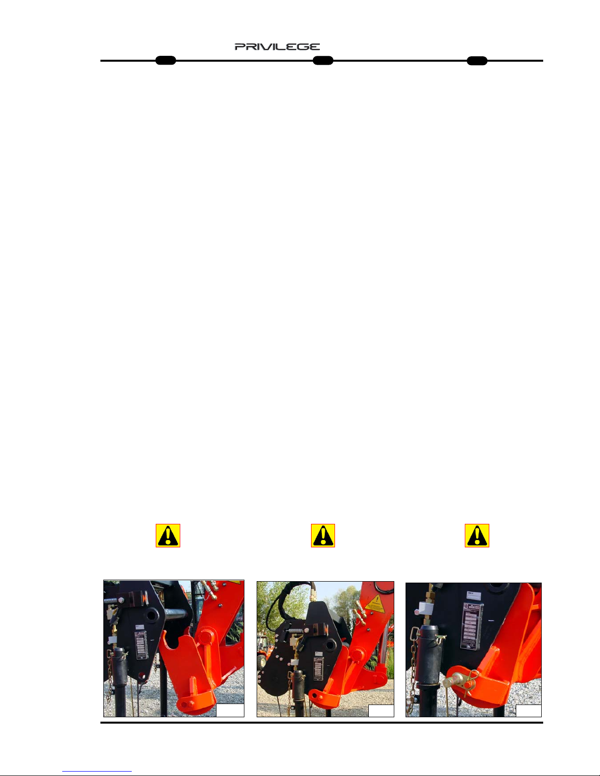
HOW TO MOUNT THE ACCESSORY
WITH MANUAL LOCK
Engaging the accessory
- Check that the accessory is in a
position which simplifies connection of
the snap coupling. If it is badly
positioned, take
the necessary precautions to move it in
the conditions of maximum safety.
- Check that the locking pin is engaged in
the support provided on the frame.
- Position the lift-truck with the boom
lowered squarely in front of and parallel
to the accessory and tilt the snap
coupling forward(Fig.A).
- Bring the snap coupling into position
below the accessory’s connection pipe,
raise the boom slightly and tilt the
connection back to position the
accessory (Fig.B).
- Raise the accessory off the ground for
easier engagement.
Manual locking
- Take the locking pin on the support and
fit it into the hole of the quick coupling
in order to lock the accessory in place
(Fig. C). Do not forget to fit on the split pin.
Manual release
- Proceed in reverse direction to the
MANUAL LOCKING procedure, taking
care to replace the locking pin in the
support on the frame.
Removing (and putting down) the
accessory.
- Proceed with the ACCESSORY
HITCHING instructions in reverse
order.
Make sure that the actual accessory is
placed in a safe position on compact,
flat ground. If the accessory has a
hydraulic circuit, connect the quick
couplings or uncouple them if the
accessory is being demounted after
having relieved the pressure from the
circuit.
Keep the snap couplings clean and pro-
tect the unused orifices with the caps
provided.
MONTAGGIO DELL’ACCESSORIO
CON BLOCCO MANUALE
Presa dell’accessorio
- Verificare che l’accessorio sia in una
posizione che faciliti l’aggancio
dell’attacco rapido. Nel caso in cui
fosse male orientato, prendete le
precauzioni necessarie per spostarlo in
condizioni di massima sicurezza.
- Verificare che il perno di bloccaggio
sia inserito nell’apposito supporto sul
telaio.
- Posizionare il carrello elevatore con il
braccio abbassato ben di fronte e
parallelo all’accessorio e inclinare
l’attacco rapido in avanti (Fig.A).
- Portare l’attacco rapido sotto il tubo
d’aggancio dell’accessorio, alzare
leggermente il braccio e inclinare
l’attacco stesso all’indietro per
posizionare l’accessorio (Fig.B).
- Disimpegnare l’accessorio dal suolo
per agevolare il bloccaggio.
Bloccaggio manuale
- Prendere il perno di bloccaggio sul
supporto e infilarlo nel foro dell’attacco
rapido per bloccare l’accessorio
(Fig. C).
Non dimenticare di mettere la copiglia.
Sbloccaggio manuale
- Procedere in senso inverso a quello
del BLOCCAGGIO MANUALE facendo
attenzione a rimettere il perno di
bloccaggio nel supporto sul telaio.
Rimozione (e posa) dell’accessorio
- Procedere in senso inverso a quello
della PRESA DELL’ACCESSORIO
facendo attenzione a posare il
medesimo in posizione sicura su suolo
compatto e piano. Se l’accessorio é
dotato di sistema idraulico, innestare
gli attacchi rapidi o viceversa
disinnestarli in caso di
smontaggio accessorio previa
decompressione del circuito.
Mantenete puliti gli innesti rapidi e
proteggete gli orifizi non utilizzati con gli
appositi tappi.
MONTAGE DES ZUBEHÖRTEILS MIT
MANUELLER VERRIEGELUNG
Einsetzen des Anbaugeräts
- Vergewissern Sie sich, daß das
Anbaugerät sich in einer Stellung befindet,
in der die
Schnellkupplung leichteinrasten kann.
Sollte das Gerät schlecht ausgerichtet sein,
ergreifen Sie alle erforderlichen
Vorsichtsmaßnahmen, um es in aller
Sicherheit versetzen zu können.
- Vergewissern Sie sich, daß sich der
Sicherungsbolzen in der entsprechenden
Halterung am Rahmen befindet.
- Positionieren Sie den Gabelstapler mit
gesenktem Arm genau gegenüber und
parallel zum Anbaugerät. Neigen Sie
die Schnellkupplung nach vorne (Abb.A).
- Bringen Sie die Schnellkupplung unter
das Kupplungsrohr des Anbaugeräts,
heben Sie den Arm leicht an und neigen
Sie die Kupplung selbst nach hinten, um
das Anbaugerät in Position zu bringen
(Abb.B).
- Heben Sie das Anbaugerät vom Boden
an, um das Einrasten zu vereinfachen.
Handverriegelung
- Den Sperrbolzen auf dem Träger nehmen
und ihn in die Öffnung der Schnellkupplung
stecken, um das Zubehörteil zu verriegeln
(Abb. C). Nicht vergessen, den
Sicherungssplint einzustecken.
Handentriegelung
- Gehen Sie in umgekehrter Reihenfolge wie
bei der HANDVERRIEGELUNG vor und
achten Sie darauf, den Sicherungsbolzen
wieder in die Halterung am Rahmen
einzusetzen.
Abnehmen (und Ablegen) des
Anbaugeräts
- In der umgekehrten Richtung zu der bei
der AUFNAHME DES ZUBEHÖRTEILS
vorgehen, wobei darauf zu achten ist, dass
dieses in einer sicheren Position auf einem
kompakten und ebenen Boden abgelegt
wird. Wenn das Zubehörteil mit hydrauli
schem System versehen ist, die
Schnellkupplung ankoppeln bzw. bei Abbau
des Zubehörteils abkoppeln, nachdem
man den Druck aus dem hydraulischen
Kreislauf abgelassen hat.
Halten Sie die Schnellkupplungen stets
sauber und schützen Sie nicht verwen-
dete Öffnungen durch entsprechende
Stopfen.
A
B
C
MRT 1850 - 2150 - 2540
Page 14

12
IT
EN
DE
5
MRT 1850 - 2150 - 2540
ACCESSORY WITHOUT HYDRAULIC
SYSTEM AND HYDRAULIC LOCKING
(OPTIONAL).
Engaging the accessory
- Check that the accessory is in a position
which simplifies connection of the snap
coupling. If it is badly positioned, take
the necessary precautions to move it in
the conditions of maximum safety.
- Check that the rods of the locking
cylinder are retracted.
- Position the lift-truck with the boom
lowered squarely in front of and parallel
to the accessory and tilt the snap
coupling forward (Fig.A).
- Bring the snap coupling into position
below the accessory’s connection pipe,
raise the boom slightly and tilt the
connection back to position the
accessory (Fig.B).
- Raise the accessory off the ground for
easier engagement.
- Operate the optional control to lock the
accessory
Hydraulic locking and release
(optional)
- Accessories are locked and released
with the optional control (which can
be operated by a button or by the
manipulator itself, depending on the
type of lift truck in question), by means
of the pins which must project from the
holes ofthe quick coupling (Fig. C).
Removing (and putting down) the
accesory
- Proceed in reverse direction to the
ENGAGING THE ACCESSORY
procedure, taking care to place it in a
safe position on firm, flat ground.
MONTAGE DES ZUBEHÖRTEILS MIT
HYDRAULISCHER VERRIEGELUNG
Einsetzen des Anbaugeräts
- Vergewissern Sie sich, daß das
Anbaugerät sich in einer Stellung
befindet, in der die Schnellkupplung
leicht einrasten kann. Sollte das Gerät
schlecht ausgerichtet sein, ergreifen
Sie alle erforderlichen
Vorsichtsmaßnahmen, um es in aller
Sicherheit versetzen zu können.
- Vergewissern Sie sich, daß die Stäbe
des Verriegelungszylinders
eingefahren sind.
- Positionieren Sie den Gabelstapler mit
gesenktem Arm genau gegenüber und
parallel zum Anbaugerät. Neigen Sie
die Schnellkupplung nach vorne (Abb.A).
- Bringen Sie die Schnellkupplung unter
das Kupplungsrohr des Anbaugeräts,
heben Sie den Arm leicht an und
neigen Sie die Kupplung selbst nach
hinten, um das Anbaugerät in Position
zu bringen (Abb.B).
- Heben Sie das Anbaugerät vom
Boden an, um das Einrasten zu
vereinfachen.
- Das Bedienelement Optional betätigen,
um das Zubehörteil zu verriegeln.
Hydraulische Ver- und Entriegelung
(wahlweise)
- Das Ver- bzw. Entriegeln eines
etwaigen Zubehörteils erfolgt über die
Benutzung des Bedienelements
Optional (Bedienelement, das je nach
dem Hubstapler, den man besitzt, mit
einer speziellen Taste oder mit dem
Vierwegschalter betätigt werden kann)
mittels der Bolzen, die aus den
Öffnungen der Schnellkupplung
austreten müssen (Fig. C).
Abnehmen (und Ablegen) des
Anbaugeräts
- Gehen Sie in umgekehrter Reihenfolge
wie beim EINSETZEN DES
ANBAUGERÄTS vor und achten Sie
darauf, das Anbaugerät in einer
sicheren Stellung auf festem, ebenem
Untergrund abzulegen.
MONTAGGIO DELL’ACCESSORIO CON
BLOCCO IDRAULICO (OPZIONAL).
Presa dell’accessorio
- Verificare che l’accessorio sia in una
posizione che faciliti l’aggancio
dell’attacco rapido. Nel caso in cui
fosse male orientato, prendete le
precauzioni necessarie per spostarlo in
condizioni di massima sicurezza.
- Verificare che le aste del martinetto di
bloccaggio siano rientrate.
- Posizionare il carrello elevatore con il
braccio abbassato ben di fronte e
parallelo all’accessorio e inclinare
l’attacco rapido in avanti (Fig.A).
- Portare l’attacco rapido sotto il tubo
d’aggancio dell’accessorio, alzare
leggermente il braccio e inclinare
l’attacco stesso all’indietro per
posizionare l’accessorio (Fig.B).
- Disimpegnare l’accessorio dal suolo
per agevolare il bloccaggio.
- Azionare il comando optional per
bloccare l’accessorio.
Bloccaggio e sbloccaggio idraulico
(opzional)
- Il bloccaggio e lo sbloccaggio di un
eventuale accessorio avviene tramite
l’utilizzo del comando optional
(comando che può essere azionato da
un apposito pulsante o dal
manipolator stesso a seconda del tipo
di carrello elevatore che si possiede)
tramite i perni che debbano fuoriuscire
dai fori dell’attacco rapido (Fig. C).
Rimozione (e posa) dell’accessorio
- Procedere in senso inverso a quello
della PRESA DELL’ACCESSSORIO
facendo attenzione a posare il
medesimo in posizione sicura su suolo
compatto e piano.
A
B
C
Page 15

13
IT
EN
DE
5
IIIINNNNDDDDIIIICCCCEEEE ---- IIIINNNNDDDDEEEEXXXX ---- IIIINNNNHHHHAAAALLLLTT
TT
ARGANO 3-4-5 Ton
WINCH 3-4-5 Ton
WINDE 3-4-5 Ton
ARGANO SU BRACCIO 6 Ton
WINCH ON THE BOOM 6 Ton
WINDE AM AUSLEGER 6 Ton
BRACCETTO P600
P600 HOIST
ARGRIFFSSCHENREL P600
BRACCETTO PT600
PT600 HOIST
ARGRIFFSSCHENREL PT600
BRACCETTO P1000
P1000 HOIST
ARGRIFFSSCHENREL P1000
BRACCETTO PT1000
PT1000 HOIST
ARGRIFFSSCHENREL PT1000
BRACCETTO P1200
P1200 HOIST
ARGRIFFSSCHENREL P1200
BRACCETTO PT1200
PT1200 HOIST
ARGRIFFSSCHENREL PT1200
BRACCETTO P1500
P1500 HOIST
ARGRIFFSSCHENREL P1500
BRACCETTO PT1500
PT1500 HOIST
ARGRIFFSSCHENREL PT1500
BRACCETTO P2000
P2000 HOIST
ARGRIFFSSCHENREL P2000
BRACCETTO PT2000
PT2000 HOIST
ARGRIFFSSCHENREL PT2000
BRACCETTO P4000
P4000 HOIST
ARGRIFFSSCHENREL P4000
BRACCETTO P6000
P6000 HOIST
ARGRIFFSSCHENREL P6000
BRACCETTO PT800
PT800 HOIST
ARGRIFFSSCHENREL PT800
BRACCETTO CON GANCIO 3-4-5 Ton
JIB WITH HOOK 3-4-5 Ton
AUSLEGER MIT AHKEN 3-4-5 Ton
PAG./ ABB.
15
33
44
45
54
55
64
65
74
75
84
85
94
95
97
106
MRT 1850 - 2150 - 2540
Page 16

Page 17
15
IT
EN
DE
5
MRT 1850 - 2150 - 2540
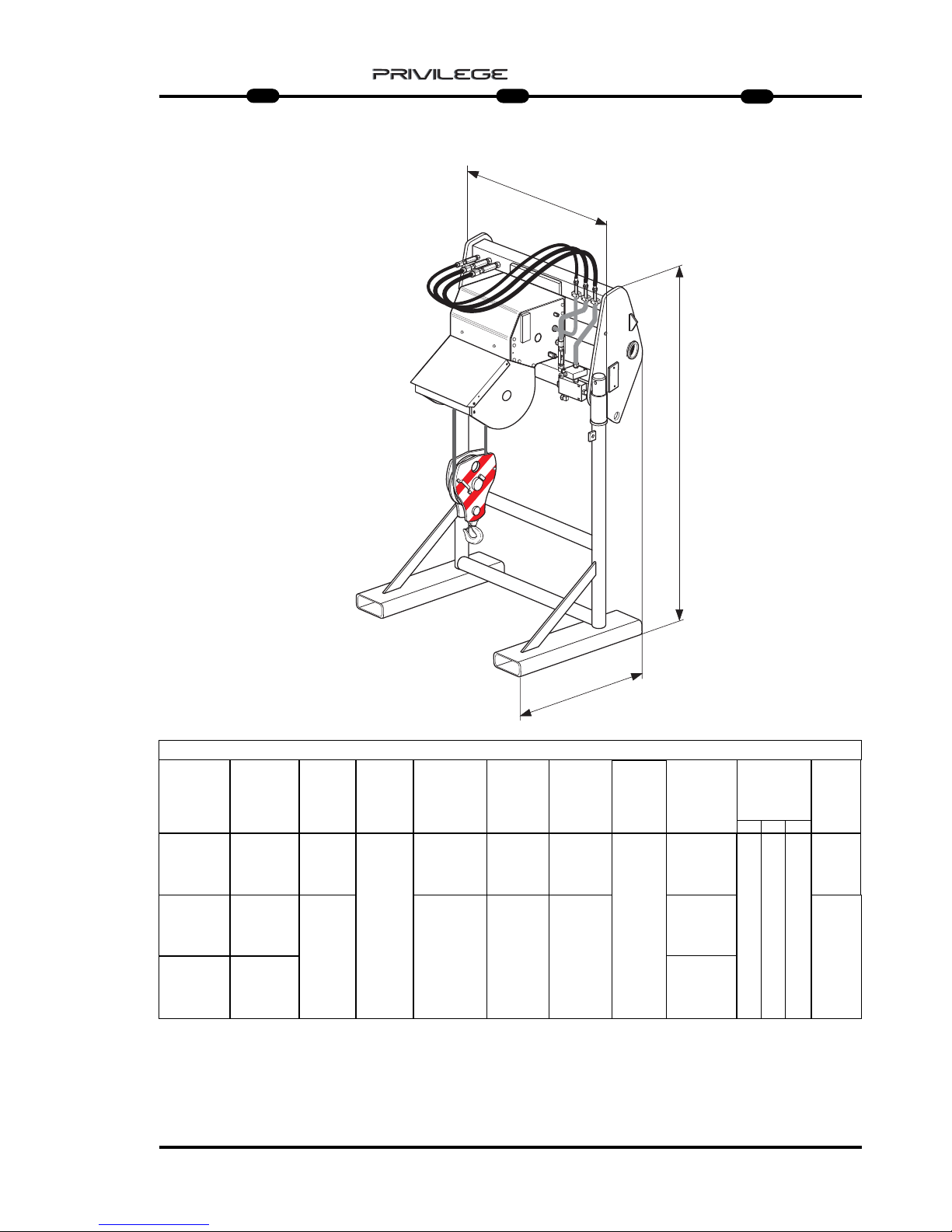
TECHNICAL CHARACTERISTICS
WINCH 3/4/5 Ton
: only for MRT 2540 and 2440 EPS
TECHNISCHE MERKMALE
WINDE 3/4/5 Ton
: only for MRT 2540 and 2440 EPS
CARATTERISTICHE TECNICHE
ARGANO 3/4/5 Ton
: solo per MRT 2540 e 2440 EPS
A
B
C
CARATTERISTICHE - CHARACTERISTICS - DATEN
DESCRIZIONE
DESIGNATION
BESCHREIBUNG
FUNE
ROPES
SEIL
VELOCITA’ GANCIO
TOW SPEED
HAKEN
GESCHWINDIGKEIT
FINE CORSA
UP/DOWN
ENDLAUF
MIS. INGOMBRO
OVERAL
LENGTH
ABMESSUNGEN
GANCIO “CE“
HOOK “CE”
HAKEN “CE”
PESO
WEIGHT
GEWITCH
ARGANO 3 T
WINCH 3 T
WINDE 3 T
3000 Kg
CON 2 FUNI
3000 Kg
WITH 2 ROPES
3000 Kg
MIT ZWEI SEILE
Ø 10 mm
9460 daN
x 45 m
(x 49 m)
24 m/min
5 T
400 Kg
PRESSIONE DI
ESERCIZIO
OPERATING
PRESSURE
BETRIEBSDRUCK
A B C
950 1440
865
ARGANO 4 T
WINCH 4 T
WINDE 4 T
4000 Kg
CON 2 FUNI
4000 Kg
WITH 2 ROPES
4000 Kg
MIT ZWEI SEILE
Ø 12 mm
16000 daN
x 45 m
(x 53 m)
462 Kg
ARGANO 5 T
WINCH 5 T
WINDE 5 T
5000 Kg
CON 2 FUNI
5000 Kg
WITH 2 ROPES
5000 Kg
MIT ZWEI SEILE
18 m/min
IDRAULICO
HYDRAULIC
HYDRAULIK
Ø
AVVOLGIMENTO
PULEGGIA
Ø WINDING
PULLEY
WICKEL-Ø
RIEMENSCHEIBE
230 mm
Ø
AVVOLGIMENTO
TAMBURO
Ø WINDING
DRUM
WICKEL-Ø
TROMMEL
233 mm
280 mm 276 mm
220 Bar max
CAPACITA’
CAPACITY
KAPAZITAET
250 Bar max
275 Bar max
Page 18
16
IT
EN
DE
5
MRT 1850 - 2150 - 2540
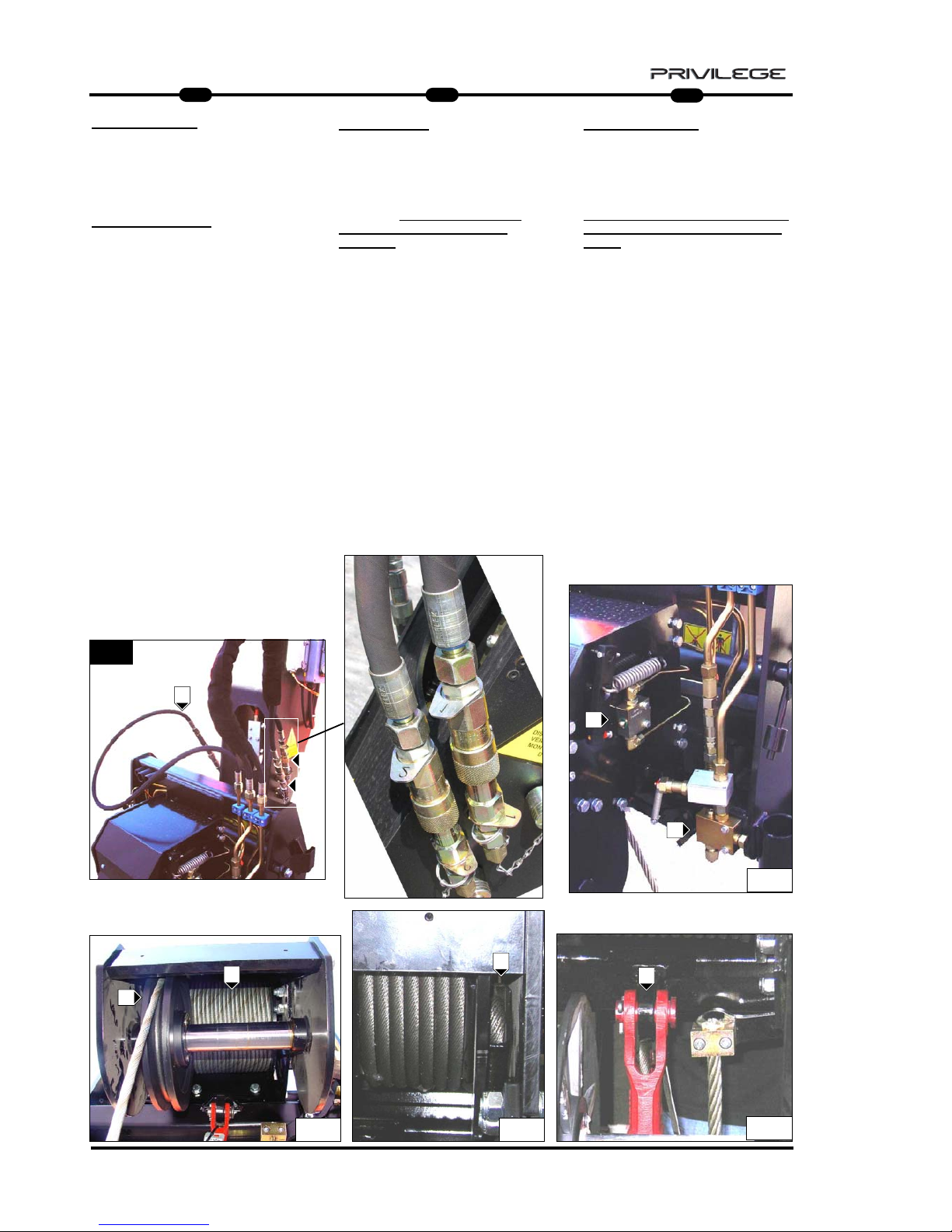
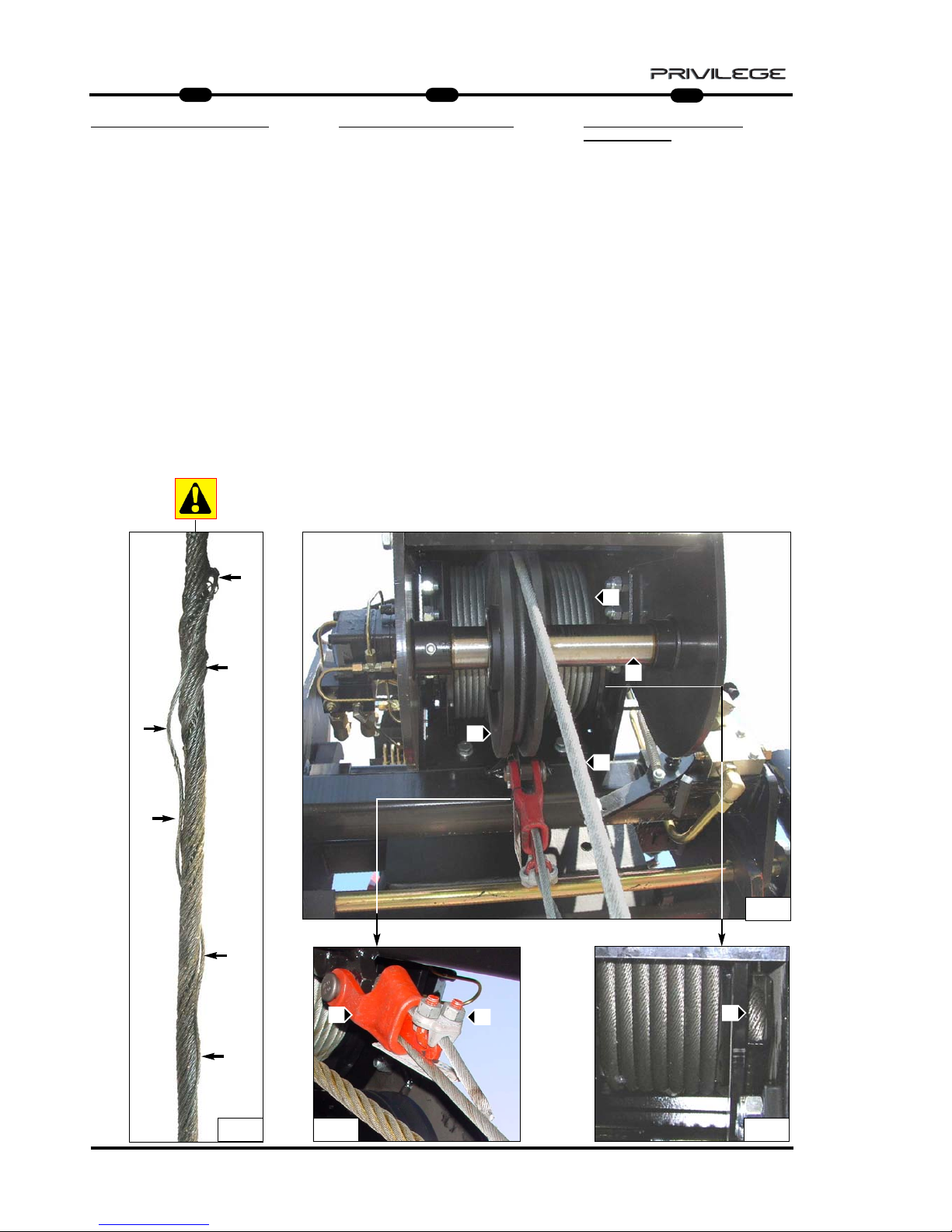
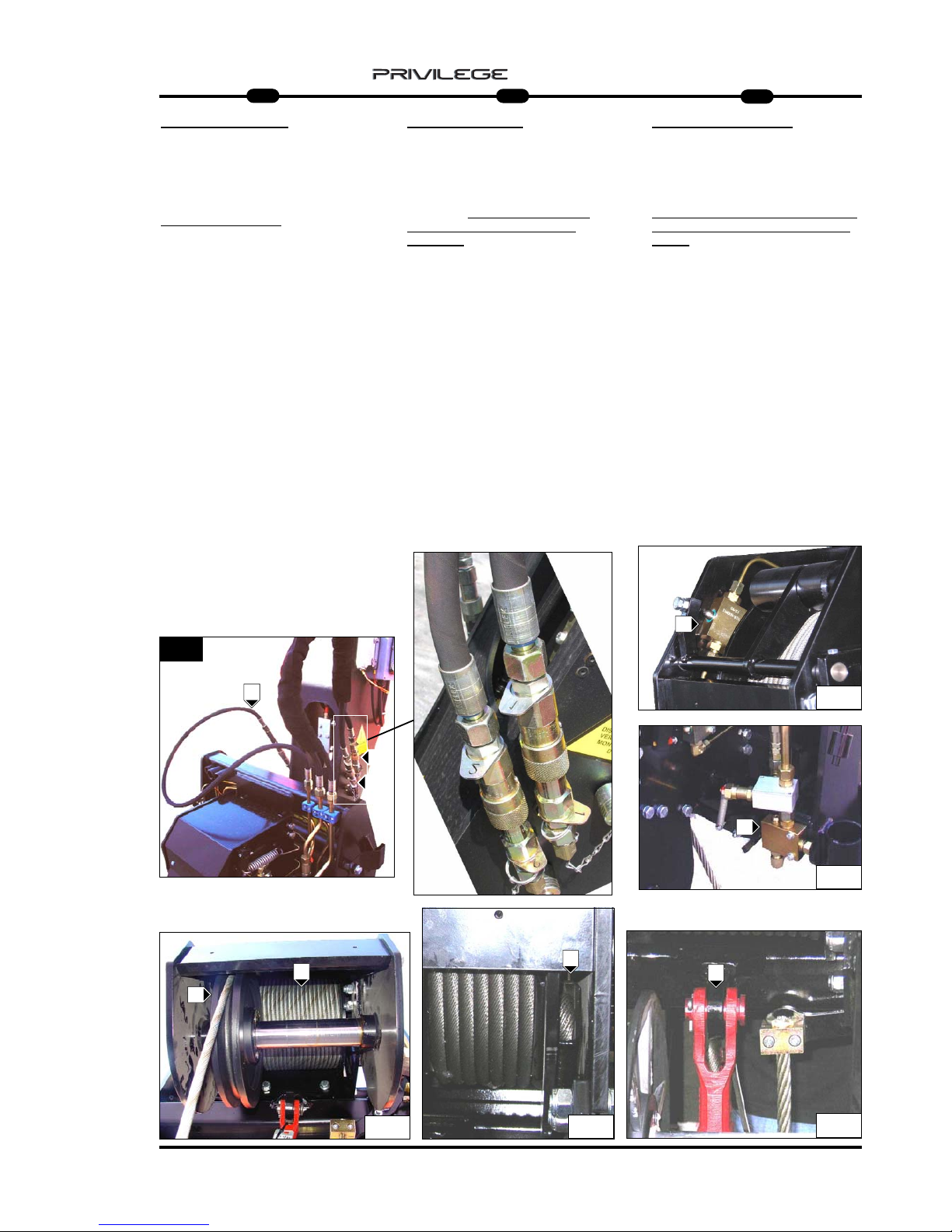
3 Ton WINCH
CCCCOOOOMMMMMMMMIIIISSSSSSSSIIIIOOOONNNNIIIINNNNGGGG AAAANNNNDDDD UUUUSSSSEE
EE
For your own safety, before starting a
work cycle, follow the compulsory
instructions for inspection and
checking:
- check the outer frame of the winch to
make sure it is intact.
- ensure correct hydraulic connection of
quick-release couplings 1, 2, check the
Drainage and the condition of the hose
pipes (Fig.1);
- check the correct working of the rope
descent limit stop H (Fig.2);
- check the correct working of the rope
lift limit stop L (Fig.2);
- check the condition of the rope and its
winding around drum A (Fig.3);
- check the correct lateral movement
and rotation of the rope guide pulleys
B (Fig.3);
- check the condition of terminal
C (Fig.4) and E (Fig.5);
WINDE 3 Tonnen
IIIINNNNBBBBEEEETTTTRRRRIIIIEEEEBBBBNNNNAAAAHHHHMMMMEEEE UUUUNNNN GGGGEEEEBBBBRRRRAAAAUUUUCCCCHH
HH
Bevor Sie einen Arbeitszyklus beginnen,
sollten Sie sich zu Ihrer Sicherheit an
die obligatorischen Prüfvorschriften
halten:
- Die Außenstruktur der Winde auf
Unversehrtheit prüfen.
- Den korrekten hydraulischen
Anschluss der Schnellkupplungen 1, 2,
der Rücklaufleitung und den Zustand
der Schläuche prüfen (Abb. 1).
- Den korrekten Betrieb des
Endschalters Seil senken H prüfen
(Abb. 2).
- Den korrekten Betrieb des
Endschalters Seil heben
L prüfen (Abb. 2).
- Den Zustand des Seils und die
korrekte Aufwicklung um die Trommel
A prüfen (Abb. 3).
- Die korrekte Seiten- und
Rotationsbewegung der
Seillenkscheibe B prüfen (Abb. 3).
- Den Zustand der Kabelschlaufen
C (Abb. 4) und E (Abb. 5) prüfen.
ARGANO 3 Ton
MMMMEEEESSSSSSSSAAAAIIIINNNN SSSSEEEERRRRVVVVIIIIZZZZIIIIOOOO EEEE UUUUTTTTIIIILLLLIIIIZZZZZZZZOO
OO
Per la vostra sicurezza, prima di iniziare
un ciclo di lavoro, attenersi alle
Istruzioni obbligatorie
di verifica e
controllo:
- verificare l’integrità della struttura
esterna dell’argano.
- verificare il corretto collegamento
idraulico degli innesti rapidi 1, 2,
Drenaggio e lo stato dei tubi flessibili
(Fig.1);
- controllare il corretto funzionamento
del fine corsa discesa fune H (Fig.2);
- controllare il corretto funzionamento
del fine corsa salita fune L (Fig.2);
- controllare lo stato della fune e il corretto
avvolgimento sul tamburo A (Fig.3);
- controllare il corretto movimento
laterale e di rotazione della puleggia di
guida fune B (Fig.3);
- controllare lo stato dei capocorda
C (Fig.4) e E (Fig.5);
1
3
4
5
A
B
C
E
D
1
2
2
H
L
Page 19
17
IT
EN
DE
5
MRT 1850 - 2150 - 2540
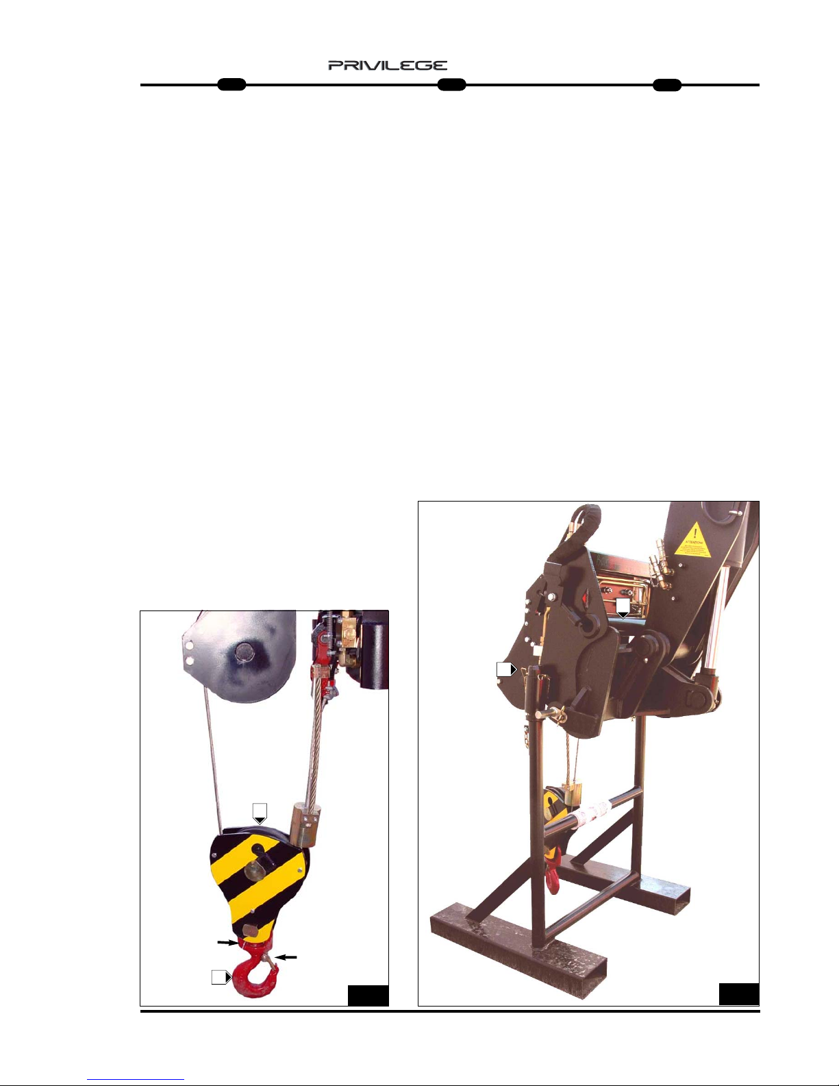
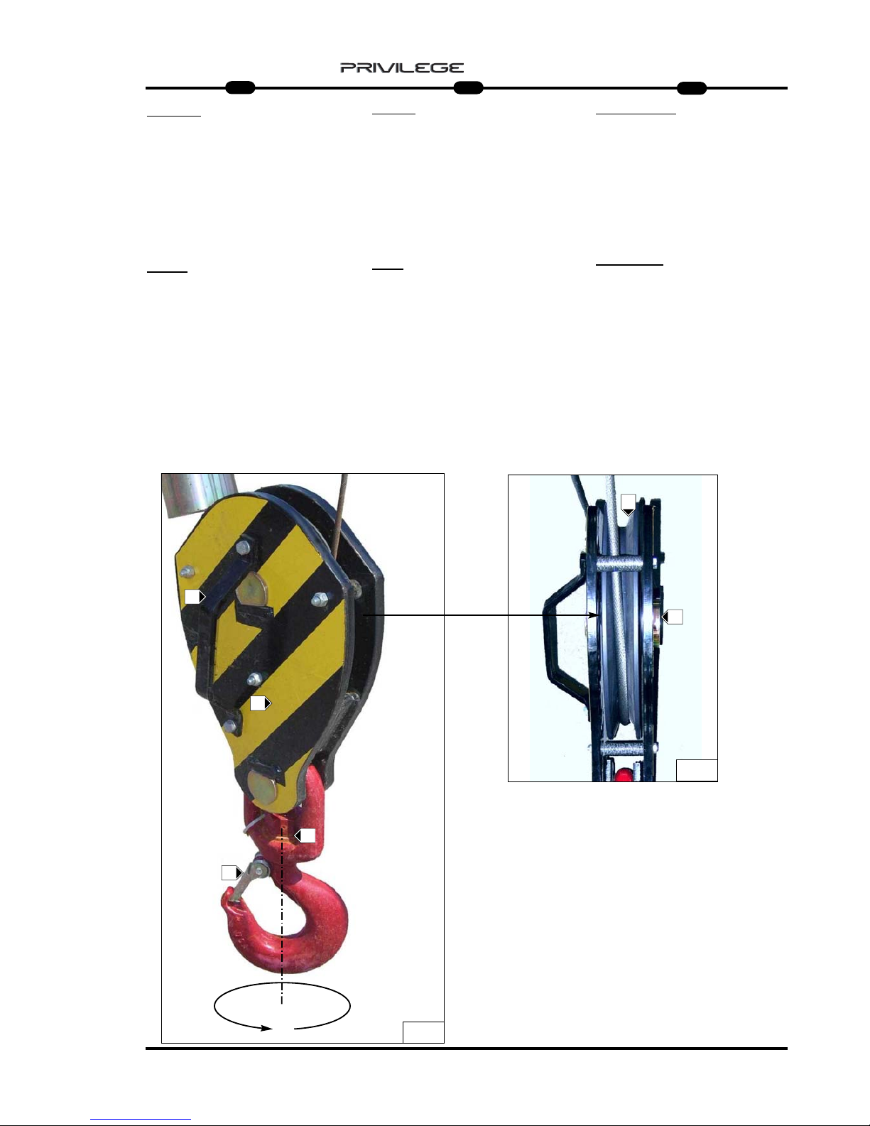
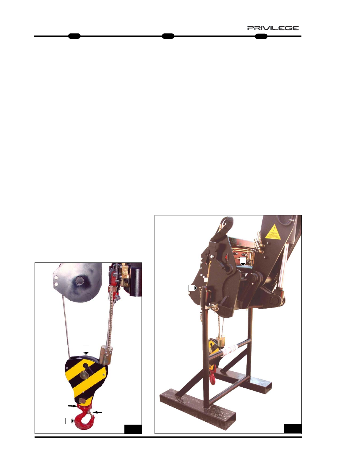
- check the condition of the block and
rotation of its pulley F (Fig.6);
- check the hook: make sure it is not
deformed, that it turns freely and that
the safety tab is efficient G (Fig.6);
- check to make sure the winch is
hooked properly to the operating machine J (Fig.7).
To use the winch, unhook it from its
pedestal, from the parking position, after
removing the safety retainers. K (Fig.7)
- Die Umlenkrolle auf ihre
Unversehrtheit und die Rotation ihrer
Riemenscheibe F prüfen (Abb. 6).
- Den Zustand des Kranhakens prüfen:
Er darf nicht deformiert sein, muss sich
frei drehen können und der
Sicherheitskeil G muss effizient sein
(Abb. 6).
- Sicherstellen, dass die Winde an der
Arbeitsmaschine J eingerastet ist
(Abb. 7).
Für die Benutzung aus der
Abstellposition die Winde von ihrem
Gestell ausklinken, wobei man die
Sicherheitsbefestigungen herauszieht.
K (Abb. 7)
- verificare l’integrità del bozzello e la
rotazione della sua puleggia F (Fig.6);
- verificare lo stato del gancio: che non
sia deformato, che ruoti liberamente e
che la linguetta di sicurezza sia
efficente G (Fig.6);
- controllare l’aggancio dell’argano alla
macchina operatrice J (Fig.7).
Per l’utilizzo, dalla posizione di
parcheggio, sganciare l’argano dal suo
piedistallo, sfilando i fermi di sicurezza.
K (Fig.7)
6
G
F
7
K
J
Page 20

18
IT
EN
DE
5
MRT 1850 - 2150 - 2540
MMMMAAAAIIIINNNNTTTTEEEENNNNAAAANNNNCCCCEEEE
- GEAR REDUCER
- ROPE, PULLEY AND TERMINAL
- BLOCK
- HOOK
- ROPE DESCENT LIMIT STOP
- ROPE LIFT LIMIT ST
OP
- HYDRAULIC SYSTEM
WWWWAAAARRRRTTTTUUUUNNNNGG
GG
- GETRIEBE
- SEIL, RIEMENSCHEIBE UND
SEILSCHLAUFE
- UMLENKROLLE
- KRANHAKEN
- ENDSCHALTER SEIL SENKEN
- ENDSCHAL
TER SEIL HEBEN
- HYDRAULISCHE ANLAGE
MMMMAAAANNNNUUUUTTTTEEEENNNNZZZZIIIIOOOONNNNEE
EE
- RIDUTTORE
- FUNE, PULEGGIA e CAPOCORDA
- BOZZELLO
- GANCIO
- FINE CORSA DISCESA FUNE
- FINE CORSA
SALITA FUNE
- IMPIANTO IDRAULICO
Page 21
19
IT
EN
DE
5
MRT 1850 - 2150 - 2540
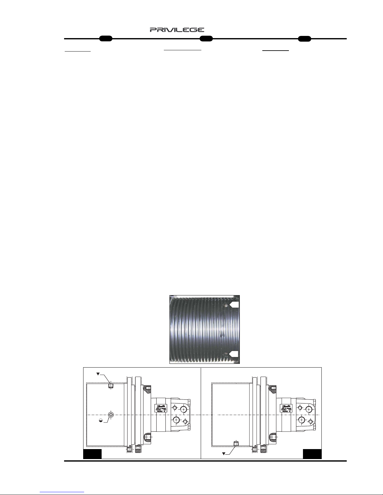
GEAR REDUCER
Correct lubrication will allow efficient
working and long life of the gear
reducer.
The rope must be unwound completely
from the drum to access the level indicator or oil filler plug.
Check the oil level at least once a
month B (Fig.8) and top up if necessary
A (Fig.8) with the same type of oil as
that present in the gear reducer
( ISO VG 150) .
Use of gear oil with EP additives, with
viscosity ISO VG, depending on the
operating temperature, is recommended.
Oil must be changed the first time
after 100 hours of operation, and subsequently every 12 months or every 2000
hours of operation.
- Change the oil with the gear reducer
still hot so that the oil drains out
completely.
- To drain out the oil, turn the motor
drum so that the filler/drain plug
A (Fig.8a) is downwards.
- Unscrew plug A (Fig.8a) and drain out
the oil completely.
- Turn the drum so that the filler/drain
plug is upwards A (Fig.8).
- Unscrew the oil level plug B (Fig.8);
- Fill with the right type of oil until it
starts flowing out through the level hole
B (Fig.8).(0,25 lt)
- Refit the plugs and rewind the rope.
GETRIEBE
Die korrekte Schmierung gewährleistet
den guten Betrieb und die lange
Haltbarkeit des Getriebes.
Um Zugriff zum Ölstand- und Öleinfüllstopfen zu erhalten, ist das Seil ganz
von der Trommel abzuwickeln.
Den Ölstand mindestens einmal im
Monat prüfen B (Abb. 8) und bei Bedarf
Öl nachfüllen A (Abb. 8). Dazu Öl der
gleichen Sorte wie das verwenden, das
im Getriebe schon vorhanden ist
( ISO VG 150).
Am besten benutzt man Öl für Getriebe
mit EP-Zusatz mit Viskosität ISO VG je
nach der Betriebstemperatur.
Der erste Ölwechsel ist nach 100
Betriebsstunden fällig, dann jeweils alle
12 Monate bzw. alle 2000
Betriebsstunden.
- Die Ölwechsel bei noch warmen
Getriebe ausführen, um des ganz
auslaufen zu können.
- Um das Öl abzulassen, die Trommel
des Motors drehen, um den Nachfüll/Ablaufstopfen A (Abb. 8a) nach unten
zu bringen.
- Den Stopfen A (Abb. 8a) losschrauben
und das Öl ganz auslaufen lassen.
- Die Trommel drehen, indem man den
Nachfüll-/Ablaufstopofen A nach oben
bringt (Abb. 8).
- Den Ölstandstopfen B abschrauben
(Abb. 8).
- Das neue Öl des korrekten Typs
nachfüllen, bis das Öl aus der
Standschraube B ausläuft
(Abb. 8).(0,25 lt)
- Die Stopfen wieder aufschrauben und
das Seil aufwickeln.
RIDUTT
ORE
Una corretta lubrificazione consente un
buon funzionamento e una lunga durata
del riduttore.
Per accedere all’indicatore di livello o al
tappo di rabbocco olio, occorre srotolare
completamente la fune dal tamburo.
Controllare il livello dell’olio almeno una
volta al mese B (Fig.8) e all’occorrenza
rabboccare A (Fig.8) con olio dello stesso
tipo di quello presente all’interno del
riduttore ( ISO VG 150) .
Si consiglia l’utilizzo di olio per ingranaggi
con addittivazione EP con viscosità ISO
VG, dipendente dalla temperatura di
esercizio.
La prima sostituzione dell’ olio deve
esser effettuata dopo 100 ore di funzionamento, successivamente ogni 12 mesi o
ogni 2000 ore di funzionamento.
-Eseguire il cambio dell’olio con riduttore
ancora caldo per facilitare un completo
svuotamento.
- Per scaricare l’olio, ruotare il tamburo del
motore portando il tappo di rabbocco /
scarico A (Fig.8a) verso il basso.
- Svitare il tappo A (Fig.8a) e scaricare
completamente l’olio.
- Ruotare il tamburo portando il foro di
rabbocco/scarico verso l’alto A (Fig.8).
- Svitare il tappo di livello olio B (Fig.8);
- Rabbocare con olio nuovo e di tipo
corretto fino a quando l’olio non fuoriesce
da foro di livelo B (Fig.8).(0,25 lt)
- Riavvitare i tappi e riavvolgere la fune.
A
A
B
8a8
B
A
Page 22
20
IT
EN
DE
5
MRT 1850 - 2150 - 2540
ROPE, PULLEY AND TERMINAL
Check rope A daily (Fig.9) to make sure
it is in perfect condition, that there are
no broken filaments (Fig.9a) and that it
is wound correctly around drum B
(Fig.9).
If this is not the case, replace it with a
new one having the same diameter and
features.
Check the lubrication of the rope, and
apply industrial grease or dust-proof
synthetic oil, if necessary.
Check and lubricate pin C (Fig.9) on
which guide pulley D (Fig.9) rotates,
on a daily basis, making sure its rotation
and transverse movements are smooth.
Lubricate the pin with lithium soap grease, if necessary.
Check the condition of terminal E
(Fig.10) and its rope-holder clamps F
(Fig.10).
SEIL, RIEMENSCHEIBE UND
SEILSCHLAUFE
Täglich prüfen, dass das Seil A (Abb. 9)
immer einen sehr guten Zustand aufweist, dass keine Seilfasern gerissen sind
(Abb. 9a) und dass das Seil gut um die
Trommel B aufgewickelt ist (Abb. 9).
Andernfalls ist das Seil durch ein neues
mit dem gleichen Durchmesser und den
gleichen Eigenschaften zu ersetzen.
Die Schmierung des Seils prüfen. Muss
es geschmiert werden, dazu ein
Industriefett oder ein synthetisches
Staubschutzfett benutzen.
Den Bolzen C (Abb. 9), auf dem sich die
Führungsscheibe D (Abb. 9) dreht, täglich prüfen und geschmiert halten. Diese
muss sich immer gut drehen und seitlich
versetzen.
Falls erforderlich, den Bolzen mit
Lithiumseifenfett schmieren.
Die Seilschlaufe E (Abb. 10) und die
Bügelklemmen F (Abb. 10) auf
Unversehrtheit prüfen.
FUNE, PULEGGIA
e CAPOCORDA
Controllare giornalmente che la fune
A (Fig.9) sia sempre in ottimo stato, che
non ci siano filamenti rotti (Fig.9a) e che
sia ben arrotolata sul tamburo B (Fig.9).
Altrimenti sostituirla con una nuova e
dello stesso diametro e caratteristiche.
Controllare la lubrificazione della fune,
se necessita lubrificare con grasso
industriale oppure olio sintetico antipolvere.
Controllare giornalmente e mantenere
lubrificato il perno C (Fig.9) su cui ruota
la puleggia di guida D (Fig.9), che dovrà
avere sempre un buono movimento di
rotazione e di traslazione laterale.
Se necessita, lubrificare con grasso al
sapone di litio il perno.
Assicurarsi dell’integrità dei capocorda
E (Fig.10) e dei suoi morsetti fermafune
F (Fig.10).
1010
9
9a
A
B
C
D
E
E
F
Page 23
21
IT
EN
DE
5
MRT 1850 - 2150 - 2540
BLOCK
For maximum efficiency and safety,
make sure the outer frame H (Fig.11) is
intact and check pulley
L (Fig.12) to make sure it rotates properly around its pin M (Fig.12) .
Lubricate pin M with lithium soap grease, if necessary (Fig.11).
HOOK
For maximum efficiency, keep the hook
rotation screw N lubricated (Fig.12).
Without load suspended, the hook must
rotate freely, merely by pressing with the
hand P (Fig.12).
Check the condition and working of
safety tab O (Fig.12).
UMLENKROLLE
Für eine maximale Effizienz und
Sicherheit die Außenstruktur H (Abb. 11)
unversehrt halten und sicherstellen,
dass die Riemenscheibe L (Abb. 12)
sich korrekt um ihren Bolzen M dreht
(Abb. 12).
Falls erforderlich, den Bolzen M mit
Lithiumseifenfett schmieren (Abb. 11).
KRANHAKEN
Für eine maximale Effizienz und
Sicherheit die Rotationsschraube des
Kranhakens N geschmiert halten
(Abb. 12).
Ohne hängende Last muss der
Kranhaken sich immer frei und nur
durch Handdruck drehen P (Abb. 12).
Den Zustand und die Effizienz des
Sicherheitskeils prüfen O (Abb. 12).
BOZZELLO
Per una massima efficenza e sicurezza,
mantenere intatta la struttura esterna
H (Fig.11) e controllare che la puleggia
L (Fig.12) ruoti correttamente sul suo perno
M (Fig.12) .
Se necessità, lubrificare con grasso al
sapone di litio il perno M (Fig.11).
GANCIO
Per una massima efficenza mantenere
lubrificata la vite di rotazione del gancio
N (Fig.12).
Senza carico sospeso, il gancio deve
sempre ruotare liberamente e con la sola
pressione della mano P (Fig.12).
Controllare lo stato e l’efficenza della
linguetta di sicurezza O (Fig.12).
L
11
12
O
N
M
H
H
P
Page 24
22
IT
EN
DE
5
MRT 1850 - 2150 - 2540
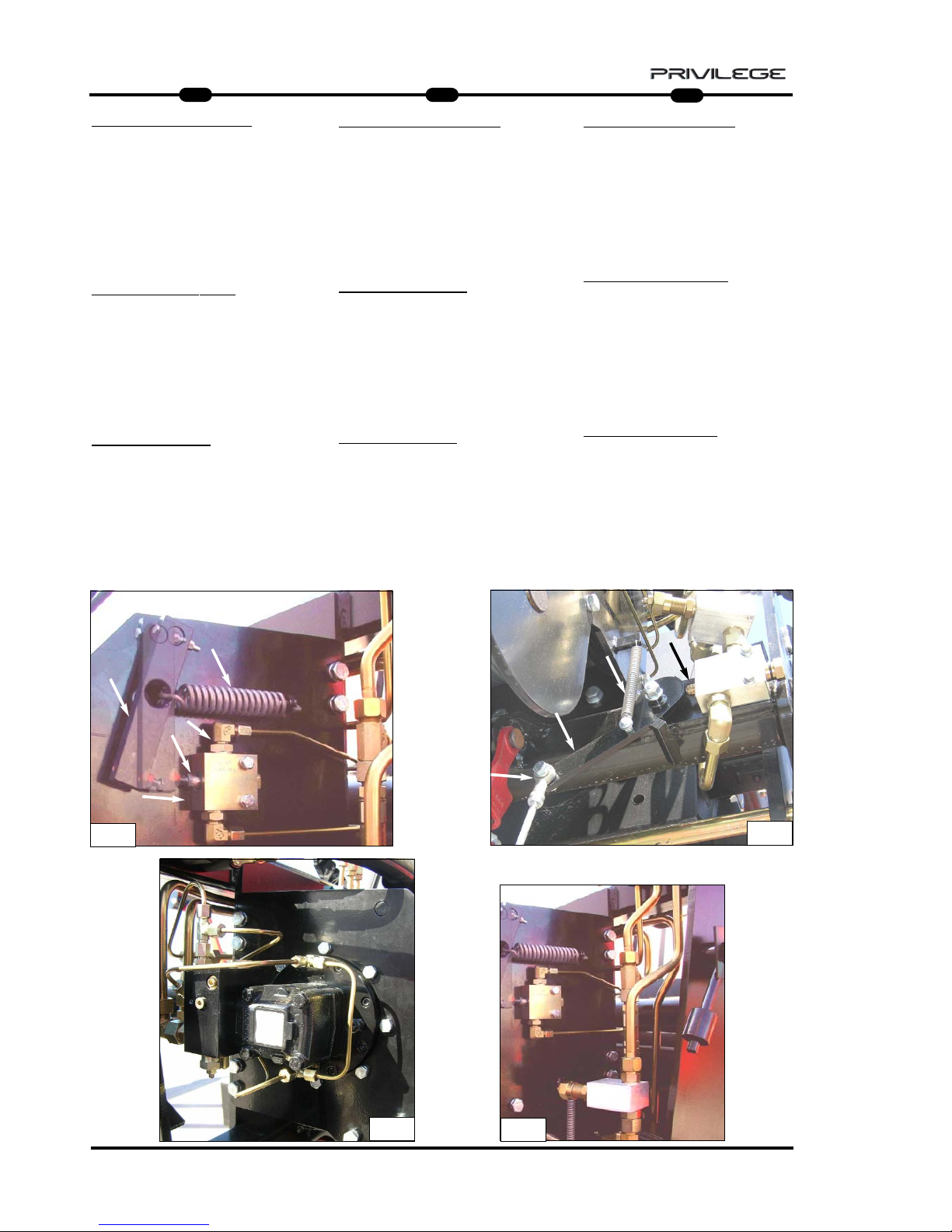
ROPE DESCENT LIMIT STOP (Fig.13)
Keep the piston and hydraulic safety
valve cleaned daily for maximum efficiency; check the unions and pipes to
make sure they are tightened properly.
Check the condition of the descent limit
stop contact leverage and the seal on its
spring.
ROPE LIFT LIMIT ST
OP
Keep the piston and hydraulic safety
valve cleaned daily for maximum efficiency; check the unions and pipes to
make sure they are tightened properly.
Also check the condition of the descent
limit stop contact leverage and the seal
on its spring. (Fig.14)
HYDRAULIC SYSTEM
(Fig.15)
Inspect the unions, valves, pipes daily to
prevent oil leakage which will affect the
working and life of the winch.
ENDSCHAL
TER SEIL SENKEN (Abb. 13)
Für die maximale Effizienz den Kolben und
das hydraulische Sicherheitsventil täglich reinigen. Den Anschluss der Verbindungen und
den Zustand der Leitungen prüfen.
Außerdem das Kontaktgestänge des
Endschalters für Seilsenken auf
Unversehrtheit und die Funktionstüchtigkeit
seiner Feder prüfen.
ENDSCHALTER SEIL HEBEN
Für die maximale Effizienz den Kolben und
das hydraulische Sicherheitsventil täglich reinigen. Den Anschluss der Verbindungen und
den Zustand der Leitungen prüfen.
Außerdem das Kontaktgestänge des
Endschalters für Seilheben auf Unversehrtheit
und die Funktionstüchtigkeit seiner Feder prüfen. (Abb. 14)
HYDRAULISCHE
ANLAGE (Abb. 15)
Anschlüsse, Ventile, Leitungen täglich prüfen,
um etwaige Leckstellen zu vermeiden, welche
die Leistung und die Haltbarkeit der Winde in
Frage stellen.
FINE CORSA
DISCESA FUNE (Fig.13)
Giornalmente per una massima efficenza
mantenere sempre pulito il pistoncino e la
valvola idraulica di sicurezza; controllare il
serraggio dei raccordi e lo stato dei tubi .
Inoltre verificare l’integrità del leveraggio di
contatto finecorsa discesa e la tenuta della
sua molla.
FINE CORSA
SALIT
A FUNE
Giornalmente per una massima efficenza
mantenere sempre pulito il pistoncino e la
valvola idraulica di sicurezza; controllare il
serraggio dei raccordi e lo stato dei tubi .
Inoltre verificare l’integrità del leveraggio di
contatto finecorsa discesa e la tenuta della
sua molla. (Fig.14)
IMPIANTO
IDRAULICO
(Fig.15)
Ispezionare giornalmente raccordi, valvole,
tubi, per evitare eventuali perdite di olio
che compromettano il rendimento e la durata dell’argano.
13
15
15
14
Page 25
23
IT
EN
DE
5
MRT 1850 - 2150 - 2540
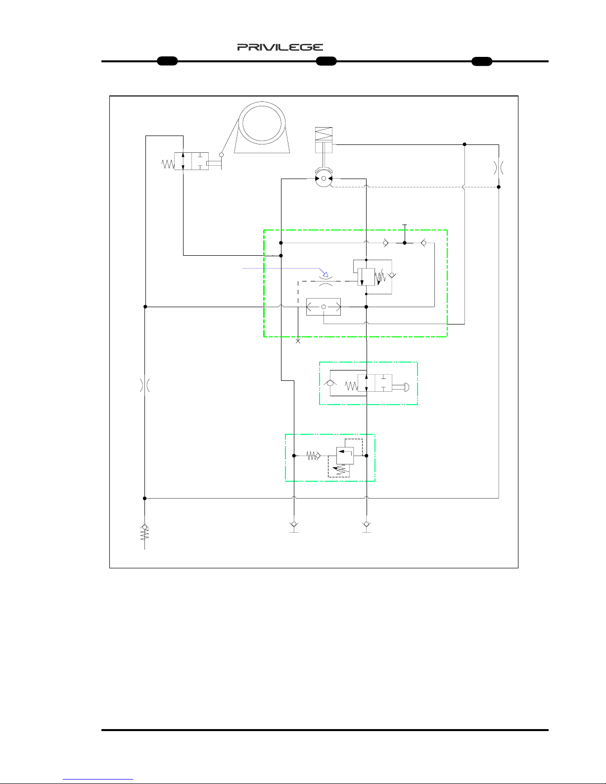
HHHHYYYYDDDDRRRRAAAAUUUULLLLIIIICCCC SSSSCCCCHHHHEEEEMMMMEE
EE
A = WINCH
N.A. = MAXIMUM DESCENT
MICROSWITCH
R = OIL TANK
I.R.1 = QUICK-RELEASE COUPLING
I.R.2 = QUICK-RELEASE COUPLING
A1 = MAXIMUM ASCENT
MICROSWITCH
S = VALVE
N = MAXIMUM PRESSURE VALVE
M = MOTOR
F = BRAKE
SSSSCCCCHHHHEEEEMMMMAAAA HHHHYYYYDDDDRRRRAAAAUUUULLLLIIIIKK
KK
A = STEHENDE WINDE
N.A. = MIKROSCHALTER MAXIMALE
SENKUNG
R = ÖLBEHÄLTER
I.R.1 = SCHNELLKUPPLUNG
I.R.2 = SCHNELLKUPPLUNG
A1 = MIKROSCHALTER MAXIMALE
HEBUNG
S = VENTIL
N = ÜBERDRUCKVENTIL
M = MOTOR
F = BREMSE
SSSSCCCCHHHHEEEEMMMMAAAA IIIIDDDDRRRRAAAAUUUULLLLIIIICCCCOO
OO
A = ARGANO
N.A. = MICRO MASSIMA
DISCESA
R = SERBATOIO OLIO
I.R.1 = INNESTO RAPIDO
I.R.2 = INNESTO RAPIDO
A1 = MICRO MASSIMA
SALITA
S = VALVOLA
N = VALVOLA MASSIMA
PRESSIONE
M = MOTORE
F = FRENO
0.80 mm
0.80 mm
250 bar
A1
M
F
N.A.
A
N
S
R
I.R. (1) I.R. (2)
C3
0.50 mm
C1 C2 D
C4
C5
V2C6V1
3mm
Winch 3T= 220 bar
Pt 1500 = 215 bar
Pt 2000 = 170 bar
Pt 800 = 150 bar
Page 26

Page 27
25
IT
EN
DE
5
MRT 1850 - 2150 - 2540
2
ARGANO 4 - 5 Ton
MMMMEEEESSSSSSSSAAAAIIIINNNN SSSSEEEERRRRVVVVIIIIZZZZIIIIOOOO EEEE UUUUTTTTIIIILLLLIIIIZZZZZZZZOO
OO
Per la vostra sicurezza, prima di iniziare
un ciclo di lavoro, attenersi alle
Istruzioni obbligatorie di verifica e
controllo:
- verificare l’integrità della struttura
esterna dell’argano.
- verificare il corretto collegamento
idraulico degli innesti rapidi 1, 2,
Drenaggio e lo stato dei tubi flessibili
(Fig.1);
- controllare il corretto funzionamento
del fine corsa discesa fune H (Fig.2);
- controllare il corretto funzionamento
del fine corsa salita fune L (Fig.2);
- controllare lo stato della fune e il corretto
avvolgimento sul tamburo A (Fig.3);
- controllare il corretto movimento
laterale e di rotazione della puleggia di
guida fune B (Fig.3);
- controllare lo stato dei capocorda
C (Fig.4) e E (Fig.5);
1
3
4
5
A
B
C
E
D
1
2
2
H
L
4 - 5 Ton WINCH
CCCCOOOOMMMMMMMMIIIISSSSSSSSIIIIOOOONNNNIIIINNNNGGGG AAAANNNNDDDD UUUUSSSSEE
EE
For your own safety, before starting a
work cycle, follow the compulsory
instructions for inspection and
checking:
- check the outer frame of the winch to
make sure it is intact.
- ensure correct hydraulic connection of
quick-release couplings 1, 2, check the
Drainage and the condition of the hose
pipes (Fig.1);
- check the correct working of the rope
descent limit stop H (Fig.2);
- check the correct working of the rope
lift limit stop L (Fig.2);
- check the condition of the rope and its
winding around drum A (Fig.3);
- check the correct lateral movement
and rotation of the rope guide pulleys
B (Fig.3);
- check the condition of terminal
C (Fig.4) and E (Fig.5);
WINDE 4 - 5 Tonnen
IIIINNNNBBBBEEEETTTTRRRRIIIIEEEEBBBBNNNNAAAAHHHHMMMMEEEE UUUUNNNN GGGGEEEEBBBBRRRRAAAAUUUUCCCCHH
HH
Bevor Sie einen Arbeitszyklus beginnen,
sollten Sie sich zu Ihrer Sicherheit an
die obligatorischen Prüfvorschriften
halten:
- Die Außenstruktur der Winde auf
Unversehrtheit prüfen.
- Den korrekten hydraulischen
Anschluss der Schnellkupplungen 1, 2,
der Rücklaufleitung und den Zustand
der Schläuche prüfen (Abb. 1).
- Den korrekten Betrieb des
Endschalters Seil senken H prüfen
(Abb. 2).
- Den korrekten Betrieb des
Endschalters Seil heben
L prüfen (Abb. 2).
- Den Zustand des Seils und die
korrekte Aufwicklung um die Trommel
A prüfen (Abb. 3).
- Die korrekte Seiten- und
Rotationsbewegung der
Seillenkscheibe B prüfen (Abb. 3).
- Den Zustand der Kabelschlaufen
C (Abb. 4) und E (Abb. 5) prüfen.
Page 28
26
IT
EN
DE
5
MRT 1850 - 2150 - 2540
- verificare l’integrità del bozzello e la
rotazione della sua puleggia F (Fig.6);
- verificare lo stato del gancio: che non
sia deformato, che ruoti liberamente e
che la linguetta di sicurezza sia
efficente G (Fig.6);
- controllare l’aggancio dell’argano alla
macchina operatrice J (Fig.7).
Per l’utilizzo, dalla posizione di
parcheggio, sganciare l’argano dal suo
piedistallo, sfilando i fermi di sicurezza.
K (Fig.7)
6
G
F
7
K
J
- check the condition of the block and
rotation of its pulley F (Fig.6);
- check the hook: make sure it is not
deformed, that it turns freely and that
the safety tab is efficient G (Fig.6);
- check to make sure the winch is
hooked properly to the operating machine J (Fig.7).
To use the winch, unhook it from its
pedestal, from the parking position, after
removing the safety retainers. K (Fig.7)
- Die Umlenkrolle auf ihre
Unversehrtheit und die Rotation ihrer
Riemenscheibe F prüfen (Abb. 6).
- Den Zustand des Kranhakens prüfen:
Er darf nicht deformiert sein, muss sich
frei drehen können und der
Sicherheitskeil G muss effizient sein
(Abb. 6).
- Sicherstellen, dass die Winde an der
Arbeitsmaschine J eingerastet ist
(Abb. 7).
Für die Benutzung aus der
Abstellposition die Winde von ihrem
Gestell ausklinken, wobei man die
Sicherheitsbefestigungen herauszieht.
K (Abb. 7)
Page 29

27
IT
EN
DE
5
MRT 1850 - 2150 - 2540
MMMMAAAAIIIINNNNTTTTEEEENNNNAAAANNNNCCCCEEEE
- GEAR REDUCER
- ROPE, PULLEY AND TERMINAL
- BLOCK
- HOOK
- ROPE DESCENT LIMIT STOP
- ROPE LIFT LIMIT STOP
- HYDRAULIC SYSTEM
WWWWAAAARRRRTTTTUUUUNNNNGG
GG
- GETRIEBE
- SEIL, RIEMENSCHEIBE UND
SEILSCHLAUFE
- UMLENKROLLE
- KRANHAKEN
- ENDSCHALTER SEIL SENKEN
- ENDSCHAL
TER SEIL
HEBEN
- HYDRAULISCHE ANLAGE
MMMMAAAANNNNUUUUTTTTEEEENNNNZZZZIIIIOOOONNNNEEEE
- RIDUTT
ORE
- FUNE, PULEGGIA e CAPOCORDA
- BOZZELLO
- GANCIO
- FINE CORSA DISCESA FUNE
- FINE CORSA SALITA FUNE
- IMPIANTO IDRAULICO
Page 30

28
IT
EN
DE
5
MRT 1850 - 2150 - 2540
GEAR REDUCER
Correct lubrication will allow efficient
working and long life of the gear
reducer.
The rope must be unwound completely
from the drum to access the level
indicator or oil filler plug.
Check the oil level every 100 hours A
(Fig.8b) and top up if necessary A
(Fig.8b) with the same type of oil as that
present in the gear reducer (SHELL
SPIRAX HD80 W90) .
Use of gear oil with EP additives with
viscosity SAE 80W/90 or SAE 85W/140
is recommended.
Oil must be changed the first time
after 150 hours of operation, and subsequently every 1000 hours of operation.
- Change the oil with the gear reducer
still hot so that the oil drains out
completely.
- To drain out the oil, turn the motor
drum so that the filler/drain plug
A (Fig.8a) is downwards.
- Unscrew plug A (Fig.8a) and drain out
the oil completely.
- Turn the drum so that the filler/drain
plug is on the horizontal axis
A (Fig.8b).
- Fill with the right type of oil until it
starts flowing out through the level hole
A (Fig.8b). . (1,3 lt)
- Refit the plugs and rewind the rope.
GETRIEBE
Die korrekte Schmierung gewährleistet
den guten Betrieb und die lange
Haltbarkeit des Getriebes.
Um Zugriff zum Ölstand- und
Öleinfüllstopfen zu erhalten, ist das Seil
ganz von der Trommel abzuwickeln.
Den Ölstand mindestens alle 100
Betriebsstunden prüfen A (Abb. 8b) und
bei Bedarf Öl nachfüllen A (Abb. 8b).
Dazu Öl der gleichen Sorte wie das
verwenden, das im Getriebe schon
vorhanden ist (SHELL SPIRAX HD80
W90).
Am besten benutzt man Öl für Getriebe
mit EP-Zusatz mit Viskosität SAE
80W/90 oder SAE 85W/140.
Der erste Ölwechsel ist nach 150
Betriebsstunden fällig, dann jeweils alle
1000 Betriebsstunden.
- Die Ölwechsel bei noch warmen
Getriebe ausführen, um des ganz
auslaufen zu können.
- Um das Öl abzulassen, die Trommel
des Motors drehen, um den Nachfüll/Ablaufstopfen A (Abb. 8a) nach unten
zu bringen.
- Den Stopfen A (Abb. 8a) losschrauben
und das Öl ganz auslaufen lassen.
- Die Trommel drehen, indem man den
Nachfüll-/Ablaufstopofen A nach oben
bringt (Abb. 8).
- Das neue Öl des korrekten Typs
nachfüllen, bis das Öl aus der
Standschraube A ausläuft (Abb. 8b).
(1,3 lt)
- Die Stopfen wieder aufschrauben und
das Seil aufwickeln.
RIDUTT
ORE
Una corretta lubrificazione consente un
buon funzionamento e una lunga durata
del riduttore.
Per accedere all’indicatore di livello o al
tappo di rabbocco olio, occorre srotolare
completamente la fune dal tamburo.
Controllare il livello dell’olio ogni 100 ore
A (Fig.8b) e all’occorrenza
rabboccare A (Fig.8b) con olio dello
stesso tipo di quello presente all’interno del
riduttore (SHELL SPIRAX HD80 W90) .
Si consiglia l’utilizzo di olio per ingranaggi
con addittivazione EP con viscosità SAE
80W/90 oppure SAE 85W/140 .
La prima sostituzione dell’ olio deve
esser effettuata dopo 150 ore di funzionamento, successivamente ogni 1000 ore di
funzionamento.
-Eseguire il cambio dell’olio con riduttore
ancora caldo per facilitare un completo
svuotamento.
- Per scaricare l’olio, ruotare il tamburo del
motore portando il tappo di rabbocco /
scarico A (Fig 8a) verso il basso.
- Svitare il tappo A (Fig.8a) e scaricare
completamente l’olio.
- Ruotare il tamburo portando il foro di
rabbocco/scarico sull’asse orizzontale
A (Fig.8b).
- Rabbocare con olio nuovo e di tipo
corretto fino a quando l’olio non fuoriesce
da foro di livelo A (Fig.8b). (1,3 lt)
- Riavvitare i tappi e riavvolgere la fune.
A
A
A
8a
8
A
8b
Page 31

29
IT
EN
DE
5
MRT 1850 - 2150 - 2540
ROPE, PULLEY and TERMINAL
Check rope A daily (Fig.9) to make sure
it is in perfect condition, that there are
no broken filaments (Fig.9a) and that it
is wound correctly around drum B
(Fig.9).
If this is not the case, replace it with a
new one having the same diameter and
features.
Check the lubrication of the rope, and
apply industrial grease or dust-proof
synthetic oil, if necessary.
Check and lubricate pin C (Fig.9) on
which guide pulley D (Fig.9) rotates,
on a daily basis, making sure its rotation
and transverse movements are smooth.
Lubricate the pin with lithium soap grease, if necessary.
Check the condition of terminal E
(Fig.10) and its rope-holder clamps F
(Fig.10).
SEIL, RIEMENSCHEIBE und SEIL
-
SCHLAUFE
Täglich prüfen, dass das Seil A (Abb. 9)
immer einen sehr guten Zustand aufweist, dass keine Seilfasern gerissen sind
(Abb. 9a) und dass das Seil gut um die
Trommel B aufgewickelt ist (Abb. 9).
Andernfalls ist das Seil durch ein neues
mit dem gleichen Durchmesser und den
gleichen Eigenschaften zu ersetzen.
Die Schmierung des Seils prüfen. Muss
es geschmiert werden, dazu ein
Industriefett oder ein synthetisches
Staubschutzfett benutzen.
Den Bolzen C (Abb. 9), auf dem sich die
Führungsscheibe D (Abb. 9) dreht, täglich prüfen und geschmiert halten. Diese
muss sich immer gut drehen und seitlich
versetzen.
Falls erforderlich, den Bolzen mit
Lithiumseifenfett schmieren.
Die Seilschlaufe E (Abb. 10) und die
Bügelklemmen F (Abb. 10) auf
Unversehrtheit prüfen.
FUNE, PULEGGIA
e CAPOCORDA
Controllare giornalmente che la fune
A (Fig.9) sia sempre in ottimo stato, che
non ci siano filamenti rotti (Fig.9a) e che
sia ben arrotolata sul tamburo B (Fig.9).
Altrimenti sostituirla con una nuova e
dello stesso diametro e caratteristiche.
Controllare la lubrificazione della fune,
se necessita lubrificare con grasso
industriale oppure olio sintetico antipolvere.
Controllare giornalmente e mantenere
lubrificato il perno C (Fig.9) su cui ruota
la puleggia di guida D (Fig.9), che dovrà
avere sempre un buono movimento di
rotazione e di traslazione laterale.
Se necessita, lubrificare con grasso al
sapone di litio il perno.
Assicurarsi dell’integrità dei capocorda
E (Fig.10) e dei suoi morsetti fermafune
F (Fig.10).
1010
9
9a
A
B
C
D
E
E
F
Page 32

30
IT
EN
DE
5
MRT 1850 - 2150 - 2540
BLOCK
For maximum efficiency and safety,
make sure the outer frame H (Fig.11) is
intact and check pulley
L (Fig.12) to make sure it rotates properly around its pin M (Fig.12) .
Lubricate pin M with lithium soap grease, if necessary (Fig.11).
HOOK
For maximum efficiency, keep the hook
rotation screw N lubricated (Fig.12).
Without load suspended, the hook must
rotate freely, merely by pressing with the
hand P (Fig.12).
Check the condition and working of
safety tab O (Fig.12).
UMLENKROLLE
Für eine maximale Effizienz und
Sicherheit die Außenstruktur H (Abb. 11)
unversehrt halten und sicherstellen,
dass die Riemenscheibe L (Abb. 12)
sich korrekt um ihren Bolzen M dreht
(Abb. 12).
Falls erforderlich, den Bolzen M mit
Lithiumseifenfett schmieren (Abb. 11).
KRANHAKEN
Für eine maximale Effizienz und
Sicherheit die Rotationsschraube des
Kranhakens N geschmiert halten
(Abb. 12).
Ohne hängende Last muss der
Kranhaken sich immer frei und nur
durch Handdruck drehen P (Abb. 12).
Den Zustand und die Effizienz des
Sicherheitskeils prüfen O (Abb. 12).
BOZZELLO
Per una massima efficenza e sicurezza,
mantenere intatta la struttura esterna
H (Fig.11) e controllare che la puleggia
L (Fig.12) ruoti correttamente sul suo perno
M (Fig.12) .
Se necessità, lubrificare con grasso al
sapone di litio il perno M (Fig.11).
GANCIO
Per una massima efficenza mantenere
lubrificata la vite di rotazione del gancio
N (Fig.12).
Senza carico sospeso, il gancio deve
sempre ruotare liberamente e con la sola
pressione della mano P (Fig.12).
Controllare lo stato e l’efficenza della
linguetta di sicurezza O (Fig.12).
L
11
12
O
N
M
H
H
P
Page 33
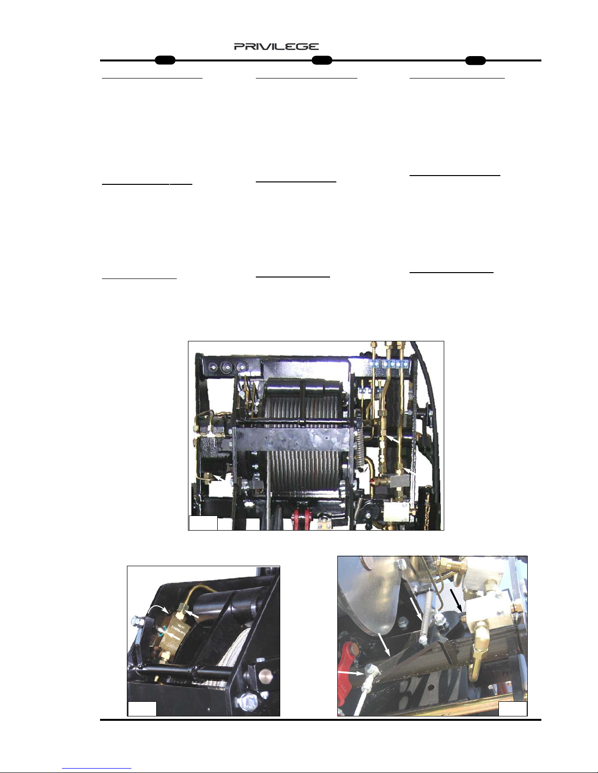
31
IT
EN
DE
5
MRT 1850 - 2150 - 2540
ROPE DESCENT LIMIT STOP (Fig.13)
Keep the piston and hydraulic safety
valve cleaned daily for maximum efficiency; check the unions and pipes to
make sure they are tightened properly.
Check the condition of the descent limit
stop contact leverage and the seal on its
spring.
ROPE LIFT LIMIT ST
OP
Keep the piston and hydraulic safety
valve cleaned daily for maximum efficiency; check the unions and pipes to
make sure they are tightened properly.
Also check the condition of the descent
limit stop contact leverage and the seal
on its spring. (Fig.14)
HYDRAULIC SYSTEM
(Fig.15)
Inspect the unions, valves, pipes daily to
prevent oil leakage which will affect the
working and life of the winch.
ENDSCHAL
TER SEIL SENKEN (Abb. 13)
Für die maximale Effizienz den Kolben und
das hydraulische Sicherheitsventil täglich reinigen. Den Anschluss der Verbindungen und
den Zustand der Leitungen prüfen.
Außerdem das Kontaktgestänge des
Endschalters für Seilsenken auf
Unversehrtheit und die Funktionstüchtigkeit
seiner Feder prüfen.
ENDSCHALTER SEIL HEBEN
Für die maximale Effizienz den Kolben und
das hydraulische Sicherheitsventil täglich reinigen. Den Anschluss der Verbindungen und
den Zustand der Leitungen prüfen.
Außerdem das Kontaktgestänge des
Endschalters für Seilheben auf Unversehrtheit
und die Funktionstüchtigkeit seiner Feder prüfen. (Abb. 14)
HYDRAULISCHE ANLAGE (Abb. 15)
Anschlüsse, Ventile, Leitungen täglich prüfen,
um etwaige Leckstellen zu vermeiden, welche
die Leistung und die Haltbarkeit der Winde in
Frage stellen.
FINE CORSA
DISCESA FUNE (Fig.13)
Giornalmente per una massima efficenza
mantenere sempre pulito il pistoncino e la
valvola idraulica di sicurezza; controllare il
serraggio dei raccordi e lo stato dei tubi .
Inoltre verificare l’integrità del leveraggio di
contatto finecorsa discesa e la tenuta della
sua molla.
FINE CORSA
SALITA
FUNE
Giornalmente per una massima efficenza
mantenere sempre pulito il pistoncino e la
valvola idraulica di sicurezza; controllare il
serraggio dei raccordi e lo stato dei tubi .
Inoltre verificare l’integrità del leveraggio di
contatto finecorsa discesa e la tenuta della
sua molla. (Fig.14)
IMPIANTO IDRAULICO (Fig.15)
Ispezionare giornalmente raccordi, valvole,
tubi, per evitare eventuali perdite di olio
che comprommettano il rendimento e la
durata dell’argano.
15
13
14
Page 34
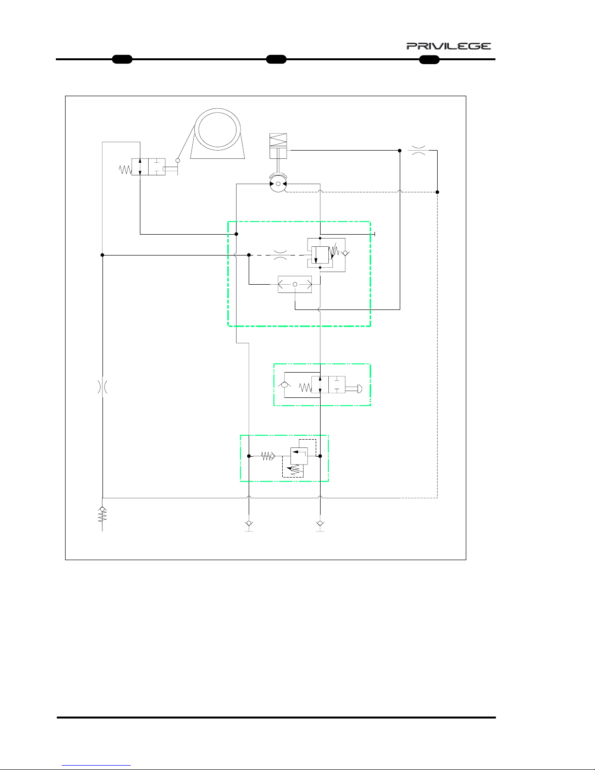
32
IT
EN
DE
5
MRT 1850 - 2150 - 2540
0.80 mm
0.80 mm
V1 V2
C3
N
C2C1
C4
C5
A1
M
F
N.A.
A
N
S
R
I.R. (1) I.R. (2)
350 bar
0.80 mm
3mm
Winch 4T= 225 bar
Winch 5T= 250 bar
Winch 6T= 275 bar
Winch 6T
on boom = 275 bar
HHHHYYYYDDDDRRRRAAAAUUUULLLLIIIICCCC SSSSCCCCHHHHEEEEMMMMEE
EE
A = WINCH
N.A. = MAXIMUM DESCENT
MICROSWITCH
R = OIL TANK
I.R.1 = QUICK-RELEASE COUPLING
I.R.2 = QUICK-RELEASE COUPLING
A1 = MAXIMUM ASCENT
MICROSWITCH
S = VALVE
N = MAXIMUM PRESSURE VALVE
M = MOTOR
F = BRAKE
SSSSCCCCHHHHEEEEMMMMAAAA HHHHYYYYDDDDRRRRAAAAUUUULLLLIIIIKK
KK
A = STEHENDE WINDE
N.A. = MIKROSCHALTER MAXIMALE
SENKUNG
R = ÖLBEHÄLTER
I.R.1 = SCHNELLKUPPLUNG
I.R.2 = SCHNELLKUPPLUNG
A1 = MIKROSCHALTER MAXIMALE
HEBUNG
S = VENTIL
N = ÜBERDRUCKVENTIL
M = MOTOR
F = BREMSE
SSSSCCCCHHHHEEEEMMMMAAAA IIIIDDDDRRRRAAAAUUUULLLLIIIICCCCOO
OO
A = ARGANO
N.A. = MICRO MASSIMA
DISCESA
R = SERBATOIO OLIO
I.R.1 = INNESTO RAPIDO
I.R.2 = INNESTO RAPIDO
A1 = MICRO MASSIMA
SALITA
S = VALVOLA
N = VALVOLA MASSIMA
PRESSIONE
M = MOTORE
F = FRENO
Page 35
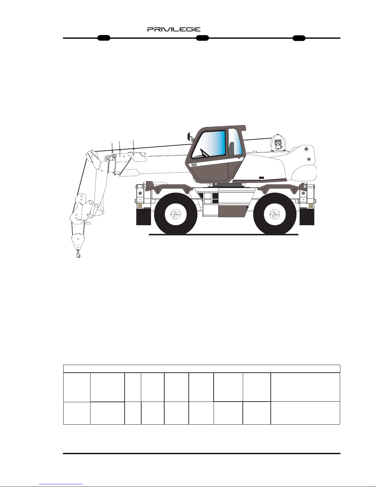
33
IT
EN
DE
5
MRT 1850 - 2150 - 2540
: only for MRT 2540 and 2440 EPS
: only for MRT 2540 and 2440 EPS
WINCH 6 TON WINDE 6 TONARGANO 6 Ton
: solo per MRT 2540 e 2440 EPS
MRT
M
Series
Turbo
CARATTERISTICHE - CHARACTERISTICS - DATEN
DESCRIZIONE
DESIGNATION
BESCHREI-
BUNG
FUNE
ROPES
SEIL
VELOCITA’ GAN-
CIO
TOW SPEED
HAKEN
GESCHWIN-
DIGKEIT
FINE CORSA
UP/DOWN
ENDLAUF
GANCIO “CE “
HOOK “CE”
HAKEN “CE”
CAPACITA’
CAPACITY
KAPAZITAET
ARGANO 6 T
WINCH 6 T
WINDE 6 T
6000 KG CON 2 FUNI
6000 KG WITH 2 ROPES
6000 KG MIT ZWEI SEILE
Ø 12 mm
x 65 m
(x 72 m)
16000 daN
18 m/min
DISCESA: IDRAULICO - SALITA: ELETTRICO
DESCENT: HYDRAULIC - ASCENT: ELECTRIC
ABSTIEG: HYDRAULISCHE - AUFSTIG: ELEKTRISCHE
6 T
PRESSIONE DI
ESERCIZIO
OPERATING
PRESSURE
BETRIEBSDRUCK
275 Bar max
Ø
AVVOLGIMENTO
PULEGGIA
Ø WINDING
PULLEY
WICKEL-Ø
RIEMENSCHEIBE
Ø
AVVOLGIMENTO
TAMBURO
Ø WINDING
DRUM
WICKEL-Ø
TROMMEL
280 mm 276 mm
Page 36

34
IT
EN
DE
5
MRT 1850 - 2150 - 2540
USING THE WINCH ON THE
BOOM
ACTIVATING THE WINCH
- Connect the hydraulic fittings to the
winch (Fig. 1 - Ref. A).
- Remove the cotter pin (Fig. 2 - Ref. B)
and extract the pin from clevis on the
outside boom (Fig. 2 - Ref. C).
- Lower the rope to let it pass through
the three rope guides (Fig. 3 - Ref. D).
- Insert the rope in the pulley, removing
the pin (Fig. 4 - Ref. E).
- Free the rope from the cable clamp
(Fig. 5 - Ref. F) after removing the
safety clamp.
- Insert the rope in the rope guide pulley
(Fig. 6 - Ref. G).
WINDENGEBRAUCH AM
AUSLEGER
WINDENAKTIVIERUNG
- Die hydraulischen Anschlußstücke mit
der Winde verbinden (Abb. 1 - Buchst.
A).
- Den Splint (Abb. 2 - Buchst. B) entfernen und den Zapfen aus dem
Ruhebügel am äußeren Ausleger (Abb.
2 - Buchst. C) herausziehen.
- Das Seil absenken, damit der
Durchgang durch die drei
Seilführungen (Abb. 3 - Buchst. D)
möglich ist.
- Das Seil in die Riemenscheibe einführen, indem man den Zapfen (Abb. 4 Buchst. E) entfernt.
- Das Seil vom Seilanschlag (Abb. 5 Bez. F) freigeben, indem man die
Seilklemme entfernt
- Das Seil in die SeilführungsRiemenscheiben (Abb. 6 - Buchst. G)
einführen.
UTILIZZO DELL’ARGANO SUL
BRACCIO
ATTIVAZIONE ARGANO
- Collegare i raccordi idraulici all’argano
(Fig. 1 - Rif. A).
- Togliere la coppiglia (Fig. 2 - Rif. B) e
sfilare il perno dalla staffa di riposo sul
braccio esterno (Fig. 2 - Rif. C).
- Comandare la discesa della fune per
permettere il passaggio attraverso i tre
guida fune (Fig. 3 - Rif. D).
- Inserire la fune nella puleggia togliendo il perno (Fig. 4 - Rif. E).
- Liberare la fune dal ferma cavo (Fig. 5
- Rif. F) togliendo il morsetto di sicurezza.
- Inserire la fune nelle pulegge guida
fune (Fig. 6 - Rif. G).
FIG. 2 FIG. 3
FIG. 5 FIG. 6FIG. 4
FIG. 1
C
B
D
D
D
E
F
F
G
G
A
A
Page 37

35
IT
EN
DE
5
MRT 1850 - 2150 - 2540
- Inserire la fune nel bozzello (Fig. 7/8 Rif. A) (la fune deve passare fra la
puleggia ed i due perni (Fig. 7/8 - Rif.
B).
- Inserire la fune nel peso di fine corsa
salita fune (Fig. 9 - Rif. C).
- Inserire la fune nel ferma cavo (Fig. 10
- Rif. D) e bloccarla correttamente
dando alcuni colpi di martello in
entrambi i lati dell’insieme (Fig. 11 Rif. E).
- Avvitare il morsetto di sicurezza fune al
ferma cavo (Fig. 12 - Rif. F).
- Montare il ferma cavo nell’apposito
alloggiamento sotto le pulegge guida
fune (Fig. 12 - Rif. G).
- Insert the rope in the block (Fig. 7/8 Ref. A) (the rope must pass through
the pulley and the two pins (Fig. 7/8 Rif. B).
- Insert the rope in the rope lift stop weight (Fig. 9 - Ref. C).
- Insert the rope in the cable clamp (Fig.
10 - Ref. D) and block it properly by
tapping with a hammer on both sides
of the assembly (Fig. 11 - Ref. E).
- Screw the safety clamp back on the
cable clamp (Fig. 12 - Ref. F).
- Fit the cable clamp in its housing under
the rope guide pulley (Fig. 12 - Ref.
G).
- Das Seil in den Kolben (Abb. 7/8 Buchst. A) einführen (das Seil muß
zwischen der Riemenscheibe und den
zwei Zapfen durchgehen (Abb. 7/8 Buchst. B).
- Das Seil in das Gewicht des
Endschalters Aufwärtshub Seil einstecken (Abb. 9 - Bez. C).
- Das Seil in den Kabelhalter (Abb. 10 Buchst. D) einführen und ordnungsgemäß festspannen, indem man an
beiden Seiten der Einheit (Abb. 11 Buchst. E) ein paar mal mit dem
Hammer klopft.
- Die Seilklemme am Seilanschlag
anschrauben (Abb. 12 - Bez. F).
- Den Seilhalter in der vorgesehenen
Aufnahme unter den SeilführungsRiemenscheiben (Abb. 12 - Buchst. G)
anbringen.
FIG. 7
FIG. 10
FIG. 9
FIG. 12
FIG. 8
FIG. 11
A
A
C
D
E
G
B
B
F
Page 38
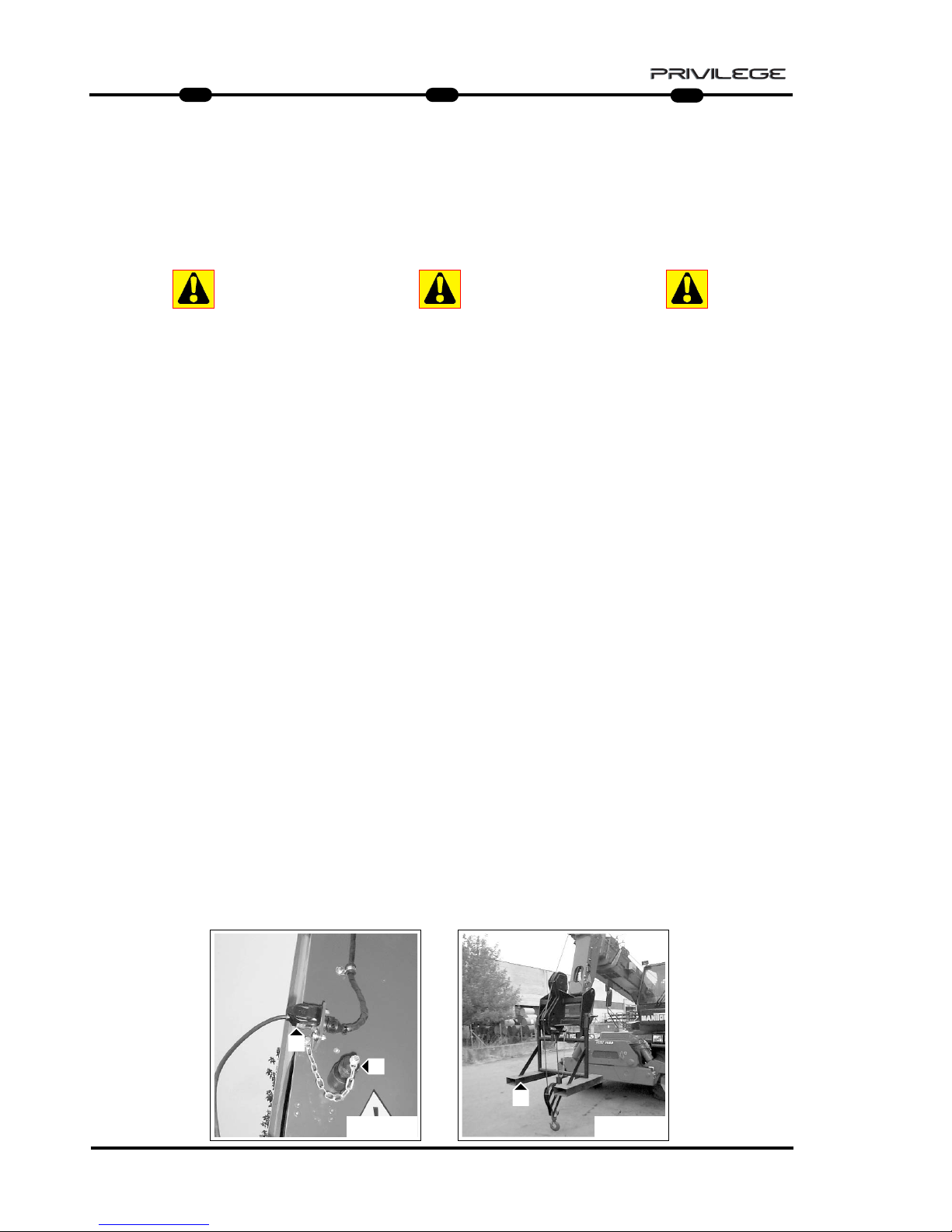
36
IT
EN
DE
5
MRT 1850 - 2150 - 2540
- Posizionare la presa a riposo (Fig. 13 Rif. A) e inserire il cavo per il fine
corsa salita fune (Fig. 13 - Rif. B).
Da questo momento si attivano i
seguenti blocchi di movimento dovuti
al fine corsa salita fune :
- blocco salita fune
- blocco sfilo braccio
- blocco salita/discesa braccio
Attenzione :
Se non viene attivato il fine corsa
salita fune é in grave pericolo :
- l’incolumità delle persone circostanti
- l’incolumità delle cose circostanti
- l’integrità strutturale della macchina
- il materiale sollevato
- Selezionare sul sistema di sicurezza la
corretta posizione di lavoro per l’argano sul braccio della macchina e togliere il supporto delle pulegge guida fune
(Fig. 14 - Rif. C).
- Position the gripper on hold (Fig. 13 Ref. A) and insert the cable for the
rope lift stop (Fig. 13 - Ref. B).
From this moment onwards, the following movement blocks are activated
due to the rope lift limitswitch :
- rope lift block
- boom extension block
- boom ascent/descent block
Attention :
If the rope lift stop is not activated
there is serious risk for the safety of:
- bystanders
- objects in the surrounding area
- the machine structure
- the material lifted
- Select on the safety system the correct
operating position for the winch on the
machine boom and remove the rope
guide pulley support (Fig. 14 - Ref. C).
- Die Steckdose in die Ruhestellung bringen
(Abb. 13 - Bez. A) und das Kabel für den
Endschalter Aufwärtshub Seil stecken
(Abb. 13 - Bez. B).
Ab diesem Moment werden folgende
Bewegungsblöcke aufgrund des
Seilhochgangs-Endschalters aktiviert :
- Block Seilhochgang
- Block Auslegerausziehung
- Block Auslegeranhebung/-absenkung
Achtung :
Wenn der Endschalter Aufwärtshub Seil
nicht aktiviert wird, besteht schwere Gefahr für:
- die Unversehrtheit der umstehenden
Personen
- die Unversehrtheit der umstehenden
Gegenstände
- die Unversehrtheit der Maschinenstruktur
- das gehobene Material
- Am Sicherheitssystem die richtige
Arbeitsstellung für die Winde am
Maschinenausleger wählen und den Träger
der Seilführungs-Riemenscheiben (Abb. 14
- Buchst. C) entfernen.
FIG. 13 FIG. 14
B
A
C
Page 39

37
IT
EN
DE
5
MRT 1850 - 2150 - 2540
INATTIVITA’ DELL’ARGANO
- Per utilizzare altri accessori, ripetere le
operazioni in ordine inverso ricordandosi di :
- mettere il cavo per il fine corsa salita
fune a riposo (Fig. 15 - Rif. A)
- inserire la presa nella spina (Fig. 16 -
Rif. B)
- scollegare i raccordi idraulici dall’ar-
gano e riporli negli appositi supporti
(Fig. 17 - Rif. C)
- riporre il bozzello nell’apposito allog-
giamento (Fig. 18 - Rif. D)
- riporre il peso di fine corsa salita fune
(Fig. 19 - Rif. E) nell’apposito perno
(Fig. 19 - Rif. F)
PUTTING AWAY THE WINCH
- To use other accessories, repeat the
operations described above in reverse
order, and remember to :
- put the rope lift limitswitch cable lying
flat (Fig. 15 - Ref. A)
- insert the plug into the socket (Fig.
16 - Ref. B)
- disconnect the hydraulic fittings from
the winch and replace them in their
supports (Fig. 17 - Ref. C)
- set the block back in its seating (Fig.
18 - Ref. D)
- set the rope lift stop weight (Fig. 19 Ref. E) back in its pin (Fig. 19 - Ref.
F)
NICHTVERWENDUNG DER WINDE
- Zur Verwendung anderer Zubehörteile, die
Vorgänge auf umgekehrte Reihenfolge wiederholen und dabei folgendes nicht vergessen :
- Das Kabel für den Endschalter des Seil
Aufwärtshub in Ruhestellung (Abb. 15 Buchst. A) bringen.
- Den Stecker in die Steckdose stecken
(Abb. 16 - Bez. B)
- Die hydraulischen Anschlußstücke von
der Winde loslösen und an den vorgesehenen Haltern (Abb. 17 - Buchst. C)
anbringen.
- Den Block in seine Aufnahme legen (Abb.
18 - Bez. D)
- Das Gewicht des Endschalters
Aufwärtshub Seil (Abb. 19 - Bez. E) in
den Bolzen (Abb. 19 - Bez. F) stecken.
FIG. 17 FIG. 19FIG. 18
C
C
FIG. 15 FIG. 16
A
B
F
D
E
Page 40

38
IT
EN
DE
5
MRT 1850 - 2150 - 2540
MMMMAAAANNNNUUUUTTTTEEEENNNNZZZZIIIIOOOONNNNEEEE
- RIDUTTORE
- FUNE, PULEGGIA e CAPOCORDA
- BOZZELLO
- GANCIO
- FINE CORSA DISCESA
FUNE
- FINE CORSA SALITA
FUNE
- IMPIANTO IDRAULICO
MMMMAAAAIIIINNNNTTTTEEEENNNNAAAANNNNCCCCEEEE
- GEAR REDUCER
- ROPE, PULLEY AND TERMINAL
- BLOCK
- HOOK
- ROPE DESCENT LIMIT STOP
- ROPE LIFT LIMIT STOP
- HYDRAULIC SYSTEM
WWWWAAAARRRRTTTTUUUUNNNNGG
GG
- GETRIEBE
- SEIL, RIEMENSCHEIBE UND
SEILSCHLAUFE
- UMLENKROLLE
- KRANHAKEN
- ENDSCHAL
TER SEIL SENKEN
- ENDSCHALTER SEIL
HEBEN
- HYDRAULISCHE ANLAGE
Page 41

39
IT
EN
DE
5
MRT 1850 - 2150 - 2540
GEAR REDUCER
Correct lubrication will allow efficient
working and long life of the gear reducer.
The rope must be unwound completely
from the drum to access the level indicator or oil filler plug.
Check the oil level every 100 hours A
(Fig.20b) and top up if necessary A
(Fig.20b) with the same type of oil as
that present in the gear reducer
(SHELL SPIRAX HD80 W90) .
Use of gear oil with EP additives with
viscosity SAE 80W/90 or SAE 85W/140
is recommended.
Oil must be changed the first time
after 150 hours of operation, and subsequently every 1000 hours of operation.
- Change the oil with the gear reducer
still hot so that the oil drains out
completely.
- To drain out the oil, turn the motor
drum so that the filler/drain plug
A (Fig.20a) is downwards.
- Unscrew plug A (Fig.20a) and drain
out the oil completely.
- Turn the drum so that the filler/drain
plug is on the horizontal axis
A (Fig.20b).
- Fill with the right type of oil until it
starts flowing out through the level hole
A (Fig.20b). (1,3 lt)
- Refit the plugs and rewind the rope.
GETRIEBE
Die korrekte Schmierung gewährleistet
den guten Betrieb und die lange
Haltbarkeit des Getriebes.
Um Zugriff zum Ölstand- und
Öleinfüllstopfen zu erhalten, ist das Seil
ganz von der Trommel abzuwickeln.
Den Ölstand mindestens alle 100
Betriebsstunden prüfen A (Abb. 20b)
und bei Bedarf Öl nachfüllen
A (Abb. 20b). Dazu Öl der gleichen
Sorte wie das verwenden, das im
Getriebe schon vorhanden ist
(SHELL SPIRAX HD80 W90).
Am besten benutzt man Öl für Getriebe
mit EP-Zusatz mit Viskosität SAE
80W/90 oder SAE 85W/140.
Der erste Ölwechsel ist nach 150
Betriebsstunden fällig, dann jeweils alle
1000 Betriebsstunden.
- Die Ölwechsel bei noch warmen
Getriebe ausführen, um des ganz
auslaufen zu können.
- Um das Öl abzulassen, die Trommel
des Motors drehen, um den Nachfüll/Ablaufstopfen A (Abb. 20a) nach unten
zu bringen.
- Den Stopfen A (Abb. 20a) losschrauben
und das Öl ganz auslaufen lassen.
- Die Trommel drehen, indem man den
Nachfüll-/Ablaufstopofen A nach oben
bringt (Abb. 20).
- Das neue Öl des korrekten Typs
nachfüllen, bis das Öl aus der
Standschraube A ausläuft (Abb. 20b)
(1,3 lt).
- Die Stopfen wieder aufschrauben und
das Seil aufwickeln.
RIDUTT
ORE
Una corretta lubrificazione consente un
buon funzionamento e una lunga durata
del riduttore.
Per accedere all’indicatore di livello o al
tappo di rabbocco olio, occorre srotolare
completamente la fune dal tamburo.
Controllare il livello dell’olio ogni 100 ore
A (Fig.20b) e all’occorrenza
rabboccare A (Fig.20b) con olio dello
stesso tipo di quello presente all’interno del
riduttore (SHELL SPIRAX HD80 W90) .
Si consiglia l’utilizzo di olio per ingranaggi
con addittivazione EP con viscosità SAE
80W/90 oppure SAE 85W/140 .
La prima sostituzione dell’ olio deve
esser effettuata dopo 150 ore di funzionamento, successivamente ogni 1000 ore di
funzionamento.
-Eseguire il cambio dell’olio con riduttore
ancora caldo per facilitare un completo
svuotamento.
- Per scaricare l’olio, ruotare il tamburo del
motore portando il tappo di rabbocco /
scarico A (Fig.20a) verso il basso.
- Svitare il tappo A (Fig.20a) e scaricare
completamente l’olio.
- Ruotare il tamburo portando il foro di
rabbocco/scarico sull’asse orizzontale
A (Fig.20b).
- Rabbocare con olio nuovo e di tipo
corretto fino a quando l’olio non fuoriesce
da foro di livelo A (Fig.20b) (1,3 lt).
- Riavvitare i tappi e riavvolgere la fune.
A
A
A
20a
20
A
20b
Page 42
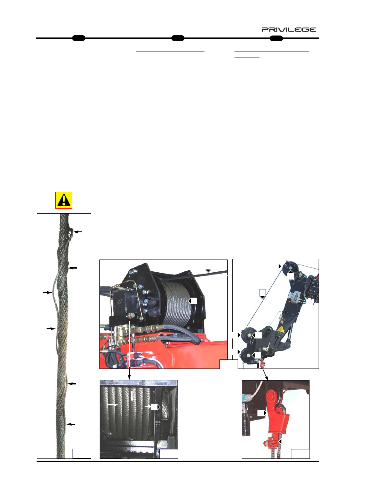
40
IT
EN
DE
5
MRT 1850 - 2150 - 2540
FUNE, PULEGGIA e CAPOCORDA
Controllare giornalmente che la fune
A (Fig.21) sia sempre in ottimo stato,
che non ci siano filamenti rotti (Fig.21a)
e che sia ben arrotolata sul tamburo B
(Fig.21).
Altrimenti sostituirla con una nuova e
dello stesso diametro e caratteristiche.
Controllare la lubrificazione della fune,
se necessita lubrificare con grasso
industriale oppure olio sintetico antipolvere.
Controllare giornalmente e mantenere
lubrificato il perno C (Fig.21) su cui
ruota la puleggia di guida D (Fig.21),
che dovrà avere sempre un buono movimento di rotazione e di traslazione laterale.
Se necessita, lubrificare con grasso al
sapone di litio il perno.
Assicurarsi dell’integrità dei capocorda
E (Fig.22) e dei suoi morsetti fermafune
F (Fig.22).
22 22
21a
B
E
E
F
21
C
D
D
D
C
C
A
A
ROPE, PULLEY and TERMINAL
Check rope A daily (Fig.21) to make
sure it is in perfect condition, that there
are no broken filaments (Fig.21a) and
that it is wound correctly around drum
B (Fig.21).
If this is not the case, replace it with a
new one having the same diameter and
features.
Check the lubrication of the rope, and
apply industrial grease or dust-proof
synthetic oil, if necessary.
Check and lubricate pin C (Fig.21) on
which guide pulley D (Fig.21) rotates,
on a daily basis, making sure its rotation
and transverse movements are smooth.
Lubricate the pin with lithium soap grease, if necessary.
Check the condition of terminal E
(Fig.22) and its rope-holder clamps F
(Fig.22).
SEIL, RIEMENSCHEIBE und SEIL
-
SCHLAUFE
Täglich prüfen, dass das Seil
A (Abb. 21) immer einen sehr guten
Zustand aufweist, dass keine Seilfasern
gerissen sind (Abb. 21a) und dass das
Seil gut um die Trommel B aufgewickelt
ist (Abb. 21).
Andernfalls ist das Seil durch ein neues
mit dem gleichen Durchmesser und den
gleichen Eigenschaften zu ersetzen.
Die Schmierung des Seils prüfen. Muss
es geschmiert werden, dazu ein
Industriefett oder ein synthetisches
Staubschutzfett benutzen.
Den Bolzen C (Abb. 21), auf dem sich
die Führungsscheibe D (Abb. 21) dreht,
täglich prüfen und geschmiert halten.
Diese muss sich immer gut drehen und
seitlich versetzen.
Falls erforderlich, den Bolzen mit
Lithiumseifenfett schmieren.
Die Seilschlaufe E (Abb. 22) und die
Bügelklemmen F (Abb. 22) auf
Unversehrtheit prüfen.
Page 43

41
IT
EN
DE
5
MRT 1850 - 2150 - 2540
BLOCK
For maximum efficiency and safety,
make sure the outer frame H (Fig.23) is
intact and check pulley
L (Fig.24) to make sure it rotates properly around its pin M (Fig.24) .
Lubricate pin M with lithium soap grease, if necessary (Fig.23).
HOOK
For maximum efficiency, keep the hook
rotation screw N lubricated (Fig.24).
Without load suspended, the hook must
rotate freely, merely by pressing with the
hand P (Fig.24).
Check the condition and working of
safety tab O (Fig.24).
UMLENKROLLE
Für eine maximale Effizienz und
Sicherheit die Außenstruktur H (Abb. 23)
unversehrt halten und sicherstellen,
dass die Riemenscheibe L (Abb. 24)
sich korrekt um ihren Bolzen M dreht
(Abb. 24).
Falls erforderlich, den Bolzen M mit
Lithiumseifenfett schmieren (Abb. 23).
KRANHAKEN
Für eine maximale Effizienz und
Sicherheit die Rotationsschraube des
Kranhakens N geschmiert halten
(Abb. 24).
Ohne hängende Last muss der
Kranhaken sich immer frei und nur
durch Handdruck drehen P (Abb. 24).
Den Zustand und die Effizienz des
Sicherheitskeils prüfen O (Abb. 24).
BOZZELLO
Per una massima efficenza e sicurezza,
mantenere intatta la struttura esterna
H (Fig.23) e controllare che la puleggia
L (Fig.24) ruoti correttamente sul suo perno
M (Fig.24) .
Se necessità, lubrificare con grasso al
sapone di litio il perno M (Fig.23).
GANCIO
Per una massima efficenza mantenere
lubrificata la vite di rotazione del gancio
N (Fig.24).
Senza carico sospeso, il gancio deve
sempre ruotare liberamente e con la sola
pressione della mano P (Fig.24).
Controllare lo stato e l’efficenza della
linguetta di sicurezza O (Fig.24).
L
23
24
O
N
M
H
H
P
Page 44

42
IT
EN
DE
5
MRT 1850 - 2150 - 2540
ENDSCHALTER SEIL SENKEN (Abb. 25)
Für die maximale Effizienz den Kolben und
das hydraulische Sicherheitsventil täglich reinigen. Den Anschluss der Verbindungen und
den Zustand der Leitungen prüfen.
Außerdem das Kontaktgestänge des
Endschalters für Seilsenken auf
Unversehrtheit und die Funktionstüchtigkeit
seiner Feder prüfen.
ENDSCHALTER SEIL HEBEN
Für die maximale Effizienz den Kolben und
das hydraulische Sicherheitsventil täglich reinigen. Den Anschluss der Verbindungen und
den Zustand der Leitungen prüfen.
Außerdem das Kontaktgestänge des
Endschalters für Seilheben auf Unversehrtheit
und die Funktionstüchtigkeit seiner Feder prüfen. (Abb. 26)
HYDRAULISCHE ANLAGE (Abb. 27)
Anschlüsse, Ventile, Leitungen täglich prüfen,
um etwaige Leckstellen zu vermeiden, welche
die Leistung und die Haltbarkeit der Winde in
Frage stellen.
FINE CORSA
DISCESA FUNE (Fig.25)
Giornalmente per una massima efficenza
mantenere sempre pulito il pistoncino e la
valvola idraulica di sicurezza; controllare il
serraggio dei raccordi e lo stato dei tubi .
Inoltre verificare l’integrità del leveraggio di
contatto finecorsa discesa e la tenuta della
sua molla.
FINE CORSA
SALITA
FUNE
Giornalmente per una massima efficenza
mantenere sempre pulito il pistoncino e il
microinterruttore; controllare il
collegamento elettrico .
Inoltre verificare l’integrità del leveraggio di
contatto finecorsa salita e la tenuta della
sua molla. (Fig.26)
IMPIANT
O IDRAULICO (Fig.27)
Ispezionare giornalmente raccordi, valvole,
tubi, per evitare eventuali perdite di olio
che comprommettano il rendimento e la
durata dell’argano.
ROPE DESCENT LIMIT ST
OP (Fig.25)
Keep the piston and hydraulic safety
valve cleaned daily for maximum efficiency; check the unions and pipes to
make sure they are tightened properly.
Check the condition of the descent limit
stop contact leverage and the seal on its
spring.
ROPE LIFT LIMIT ST
OP
Keep the piston and safety microswitch
cleaned daily for maximum efficiency;
check the connection electrical.
Also check the condition of the lift limit
stop contact leverage and the seal on its
spring. (Fig.26)
HYDRAULIC SYSTEM
(Fig.27)
Inspect the unions, valves, pipes daily to
prevent oil leakage which will affect the
working and life of the winch.
27
25
26
Page 45

43
IT
EN
DE
5
MRT 1850 - 2150 - 2540
0.80 mm
0.80 mm
V1 V2
C3
N
C2C1
C4
C5
A1
M
F
N.A.
A
N
S
R
I.R. (1) I.R. (2)
350 bar
0.80 mm
3mm
Winch 4T= 225 bar
Winch 5T= 250 bar
Winch 6T= 275 bar
Winch 6T
on boom = 275 bar
HHHHYYYYDDDDRRRRAAAAUUUULLLLIIIICCCC SSSSCCCCHHHHEEEEMMMMEE
EE
A = WINCH
N.A. = MAXIMUM DESCENT
MICROSWITCH
R = OIL TANK
I.R.1 = QUICK-RELEASE COUPLING
I.R.2 = QUICK-RELEASE COUPLING
A1 = MAXIMUM ASCENT
MICROSWITCH
S = VALVE
N = MAXIMUM PRESSURE VALVE
M = MOTOR
F = BRAKE
SSSSCCCCHHHHEEEEMMMMAAAA HHHHYYYYDDDDRRRRAAAAUUUULLLLIIIIKK
KK
A = STEHENDE WINDE
N.A. = MIKROSCHALTER MAXIMALE
SENKUNG
R = ÖLBEHÄLTER
I.R.1 = SCHNELLKUPPLUNG
I.R.2 = SCHNELLKUPPLUNG
A1 = MIKROSCHALTER MAXIMALE
HEBUNG
S = VENTIL
N = ÜBERDRUCKVENTIL
M = MOTOR
F = BREMSE
SSSSCCCCHHHHEEEEMMMMAAAA IIIIDDDDRRRRAAAAUUUULLLLIIIICCCCOO
OO
A = ARGANO
N.A. = MICRO MASSIMA
DISCESA
R = SERBATOIO OLIO
I.R.1 = INNESTO RAPIDO
I.R.2 = INNESTO RAPIDO
A1 = MICRO MASSIMA
SALITA
S = VALVOLA
N = VALVOLA MASSIMA
PRESSIONE
M = MOTORE
F = FRENO
Page 46
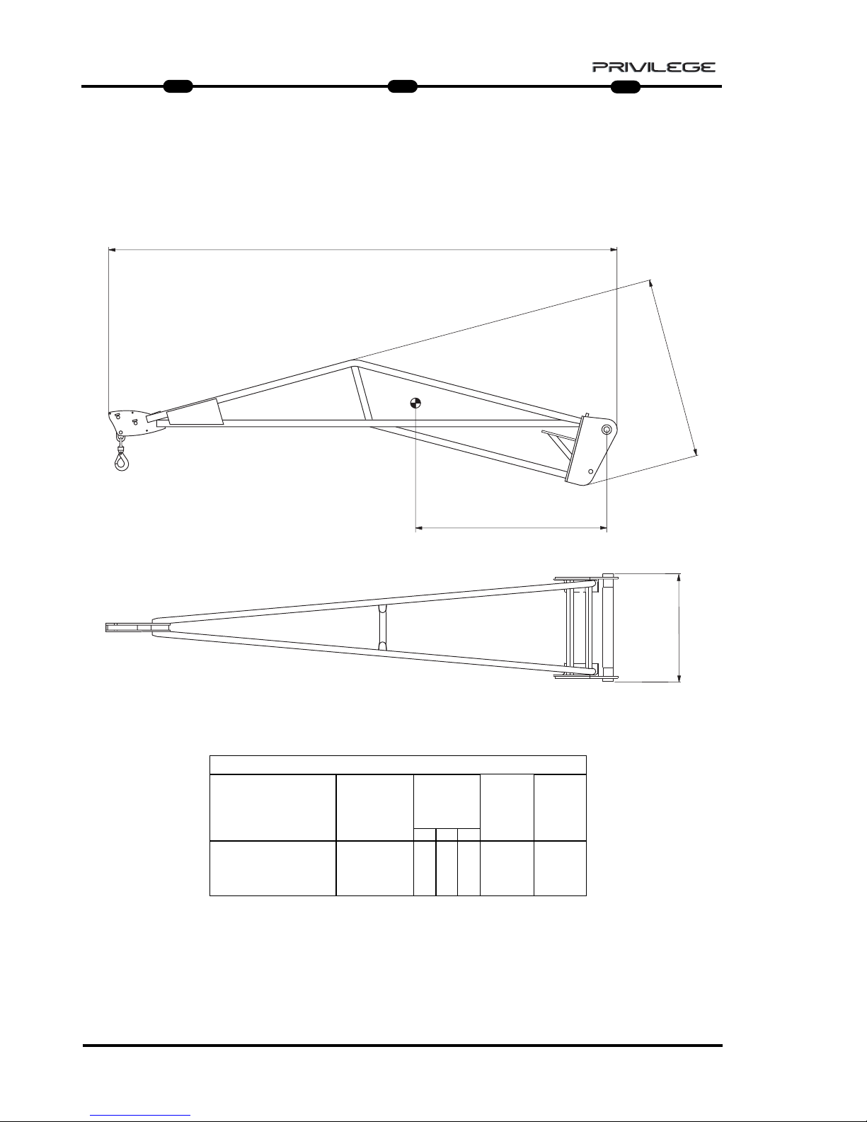
44
IT
EN
DE
5
MRT 1850 - 2150 - 2540
HOIST P 600 P 600 ANGRIFFSSCHENRELBRACCETTO P 600
B
D
C
A
CARATTERISTICHE - CHARACTERISTICS - DATEN
DESCRIZIONE
DESIGNATION
BESCHREIBUNG
MIS. INGOMBRO
OVERAL
LENGTH
ABMESSUNGEN
ACCESSORIO
ATTACHMENT
ZUBEHOER
D
PESO
WEIGHT
GEWITCH
P 600
600 Kg
1200
190 Kg
CAPACITA’
CAPACITY
KAPAZITAET
A B
C
830
815
4027
Page 47
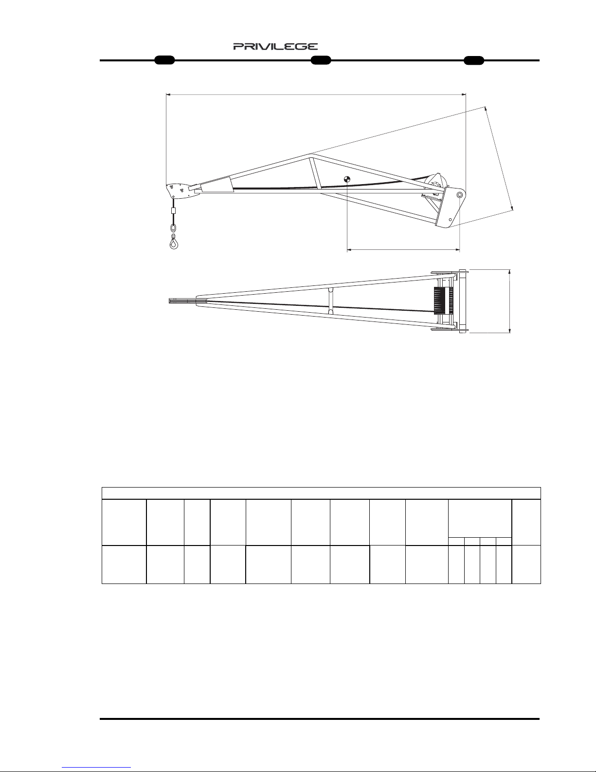
45
IT
EN
DE
5
MRT 1850 - 2150 - 2540
HOIST WITH WINCH PT 600
: only for MRT 2540 and 2440 EPS
PT 600 ANGRIFFSSCHENREL
: only for MRT 2540 and 2440 EPS
BRACCETTO PT 600
: solo per MRT 2540 e 2440 EPS
B
D
C
A
PT 600
600 Kg
IDRAULICO
HYDRAULIC
HYDRAULIK
320 Kg830 815 4027
CARATTERISTICHE - CHARACTERISTICS - DATEN
DESCRIZIONE
DESIGNATION
BESCHREIBUNG
FUNE
ROPES
SEIL
VELOCITA’ GANCIO
TOW SPEED
HAKEN
GESCHWINDIGKEIT
FINE CORSA
UP/DOWN
ENDLAUF
MIS. INGOMBRO
OVERAL LENGTH
ABMESSUNGEN
mm
GANCIO “CE“
HOOK “CE”
HAKEN “CE”
PESO
WEIGHT
GEWITCH
Ø 6 mm
x 30 m
(x 34 m)
45 m/min
PRESSIONE DI
ESERCIZIO
OPERATING
PRESSURE
BETRIEB-
SDRUCK
A B C
5 T
230 mm 233 mm
185 Bar max
CAPACITA’
CAPACITY
KAPAZITAET
D
1200
Ø
AVVOLGIMENTO
PULEGGIA
Ø WINDING
PULLEY
WICKEL-Ø
RIEMENSCHEIBE
Ø
AVVOLGIMENTO
TAMBURO
Ø WINDING
DRUM
WICKEL-Ø
TROMMEL
Page 48

46
IT
EN
DE
5
MRT 1850 - 2150 - 2540
PT 600
CCCCOOOOMMMMMMMMIIIISSSSSSSSIIIIOOOONNNNIIIINNNNGGGG AAAANNNNDDDD UUUUSSSSEE
EE
For your safety, before starting a work
cycle, follow the compulsory instruc-
tions for inspection and checking:
- check the outer frame of the winch and
the trestle arm.
- ensure correct hydraulic connection of
quick-release couplings 1, 2,
Drainage and the condition of the hose
pipes (Fig.1);
- check the correct working of the rope
descent limit stop H (Fig.2);
- check the correct working of the rope
lift limit stop L (Fig.2);
PT 600
IIIINNNNBBBBEEEETTTTRRRRIIIIEEEEBBBBNNNNAAAAHHHHMMMMEEEE UUUUNNNN GGGGEEEEBBBBRRRRAAAAUUUUCCCCHH
HH
Bevor Sie einen Arbeitszyklus beginnen,
sollten Sie sich zu Ihrer Sicherheit an
die obligatorischen Prüfvorschriften
halten:
- Die Außenstruktur der Winde und des
Gittermastauslegers auf Unversehrtheit
prüfen.
- Den korrekten hydraulischen Anschluss
der Schnellkupplungen 1, 2, der
Rücklaufleitung und den Zustand der
Schläuche prüfen (Abb. 1).
- Den korrekten Betrieb des Endschalters
Seil senken H prüfen (Abb. 2).
- Den korrekten Betrieb des Endschalters
Seil heben L prüfen (Abb. 2).
PT 600
MMMMEEEESSSSSSSSAAAAIIIINNNN SSSSEEEERRRRVVVVIIIIZZZZIIIIOOOO EEEE UUUUTTTTIIIILLLLIIIIZZZZZZZZOO
OO
Per la vostra sicurezza, prima di iniziare
un ciclo di lavoro, attenersi alle
Istruzioni obbligatorie di verifica e
controllo:
- verificare l’integrità della struttura
esterna dell’argano e del braccetto
tralicciato.
- verificare il corretto collegamento
idraulico degli innesti rapidi 1, 2,
Drenaggio e lo stato dei tubi flessibili
(Fig.1);
- controllare il corretto funzionamento
del fine corsa discesa fune H (Fig.2);
- controllare il corretto funzionamento
del fine corsa salita fune L (Fig.2);
2
1
2
H
L
D
1
2
F1
Page 49

47
IT
EN
DE
5
MRT 1850 - 2150 - 2540
- check the condition of the rope
B (Fig.3) and its winding around drum
A (Fig.3);
- check the correct movement and
rotation of the rope guide pulleys
F1 (Fig.2);
- check the condition of terminal
C (Fig.3);
- check to make sure the shackle
connecting the rope and hook is
screwed on properly K (Fig.4) and that
terminals K1 (Fig.4) block the rope.
- check the hook: make sure it is not
deformed, that it turns freely and that
the safety tab is efficient G (Fig.4);
- check the hooking of the arm to the
operating machine J (Fig.5).
From the parking position, it is possible
to unhook the supporting feet and position it inside the arm to work without
further impediment J1 (Fig.5).
- Den Zustand des Seils B prüfen
(Abb. 3) und die korrekte Aufwicklung
um die Trommel A prüfen (Abb. 3).
- Die korrekte Seiten- und
Rotationsbewegung der
Seillenkscheibe F1 prüfen (Abb. 2).
- Den Zustand der Kabelschlaufen
C (Abb. 3) prüfen.
- Sicherstellen, dass der
Seilverbindungsschäkel und der
Kranhaken gut eingeschraubt sind
K (Abb. 4) und dass die Klemmen
K1 (Abb. 4) das Seil blockieren.
- Den Zustand des Kranhakens prüfen:
Er darf nicht deformiert sein, muss sich
frei drehen können und der
Sicherheitskeil G muss effizient sein
(Abb. 4).
- Sicherstellen, dass die Winde an der
Arbeitsmaschine J eingerastet ist
(Abb. 5).
Aus der Abstellposition die Winde kann
man den Abstellfuß ausklinken und ihn
innerhalb des Auslegers anordnen, ohne
noch mehr Platz in Anspruch zu
nehmen. J1 (Abb. 5)
- controllare lo stato della fune B (Fig.3)
e il corretto avvolgimento sul tamburo
A (Fig.3);
- controllare il corretto movimento
rotazione delle puleggie di
guida fune F1 (Fig.2);
- controllare lo stato del capocorda
C (Fig.3);
- controllare che il grillo di collegamento
fune e gancio sia ben avvitato K (Fig.4)
e che i morsetti K1 (Fig.4) blocchino la fune.
- verificare lo stato del gancio: che non
sia deformato, che ruoti liberamente e
che la linguetta di sicurezza sia
efficente G (Fig.4);
- controllare l’aggancio del braccetto alla
macchina operatrice J (Fig.5).
Dalla posizione di parcheggio è possibile
sganciare il piede di appoggio e
posizionarlo all’interno del braccetto per
operare senza ulteriori ingombri J1 (Fig.5).
3
A
B
4
5
G
J1
J
C
K
K1
K1
Page 50

48
IT
EN
DE
5
MRT 1850 - 2150 - 2540
MMMMAAAAIIIINNNNTTTTEEEENNNNAAAANNNNCCCCEEEE
- GEAR REDUCER
- ROPE, PULLEY AND TERMINAL
- SHACKLE E CLAMPS
- HOOK
- ROPE DESCENT LIMIT STOP
- ROPE LIFT LIMIT ST
OP
- HYDRAULIC SYSTEM
WWWWAAAARRRRTTTTUUUUNNNNGG
GG
- GETRIEBE
- SEIL, RIEMENSCHEIBE UND
SEILSCHLINGE
- SCHÄKEL UND KLEMMEN
- KRANHAKEN
- ENDSCHALTER SEIL SENKEN
- ENDSCHALTER TEIL
HEBEN
- HYDRAULISCHE ANLAGE
MMMMAAAANNNNUUUUTTTTEEEENNNNZZZZIIIIOOOONNNNEEEE
- RIDUTTORE
- FUNE, PULEGGIA e CAPOCORDA
- GRILLO e MORSETTI
- GANCIO
- FINE CORSA DISCESA
FUNE
- FINE CORSA
SALITA FUNE
- IMPIANTO
IDRAULICO
Page 51

49
IT
EN
DE
5
MRT 1850 - 2150 - 2540
GEAR REDUCER
Correct lubrication will allow efficient
working and long life of the gear r
educer.
The rope must be unwound completely
from the drum to access the level indicator or oil filler plug.
Check the oil level every 100 hours
A (Fig.6b) and top up if necessary
A (Fig.6b) with the same type of oil as
that present in the gear reducer
(SHELL SPIRAX HD80 W90) .
Use of gear oil with EP additives with
viscosity SAE 80W/90 or SAE 85W/140
is recommended.
Oil must be changed the first time
after 150 hours of operation, and subsequently every 1000 hours of operation.
- Change the oil with the gear reducer
still hot so that the oil drains out
completely.
- To drain out the oil, turn the motor
drum so that the filler/drain plug
A (Fig.6a) is downwards.
- Unscrew plug A (Fig.6a) and drain out
the oil completely.
- Turn the drum so that the filler/drain
plug is on the horizontal axis A (Fig.6b).
- Fill with the right type of oil until it
starts flowing out through the level hole
A (Fig.6b). (0,6 lt)
- Refit the plugs and rewind the rope.
GETRIEBE
Die korrekte Schmierung gewährleistet
den guten Betrieb und die lange
Haltbarkeit des Getriebes.
Um Zugriff zum Ölstand- und Öleinfüllstopfen zu erhalten, ist das Seil ganz
von der Trommel abzuwickeln.
Den Ölstand mindestens alle 100
Betriebsstunden prüfen A (Abb. 6b) und
bei Bedarf Öl nachfüllen A (Abb. 6b).
Dazu Öl der gleichen Sorte wie das
verwenden, das im Getriebe
schon vorhanden ist
(SHELL SPIRAX HD80 W90).
Am besten benutzt man Öl für Getriebe
mit EP-Zusatz mit Viskosität
SAE 80W/90 oder SAE 85W/140.
Der erste Ölwechsel ist nach 150
Betriebsstunden fällig, dann jeweils alle
1000 Betriebsstunden.
- Die Ölwechsel bei noch warmen
Getriebe ausführen, um des ganz
auslaufen zu können.
- Um das Öl abzulassen, die Trommel
des Motors drehen, um den Nachfüll/Ablaufstopfen A (Abb. 6a) nach unten
zu bringen.
- Den Stopfen A (Abb. 6a) losschrauben
und das Öl ganz auslaufen lassen.
- Die Trommel drehen, indem man den
Nachfüll-/Ablaufstopofen A nach oben
bringt (Abb. 6).
- Das neue Öl des korrekten Typs
nachfüllen, bis das Öl aus der
Standschraube A ausläuft
(Abb. 6b).(0,6 lt)
- Die Stopfen wieder aufschrauben und
das Seil aufwickeln.
RIDUTT
ORE
Una corretta lubrificazione consente un
buon funzionamento e una lunga durata
del riduttore.
Per accedere all’indicatore di livello o al
tappo di rabbocco olio, occorre srotolare
completamente la fune dal tamburo.
Controllare il livello dell’olio ogni 100 ore
A (Fig.6b) e all’occorrenza
rabboccare A (Fig.6b) con olio dello
stesso tipo di quello presente all’interno del
riduttore (SHELL SPIRAX HD80 W90) .
Si consiglia l’utilizzo di olio per ingranaggi
con addittivazione EP con viscosità SAE
80W/90 oppure SAE 85W/140 .
La prima sostituzione dell’ olio deve
esser effettuata dopo 150 ore di funzionamento, successivamente ogni 1000 ore di
funzionamento.
-Eseguire il cambio dell’olio con riduttore
ancora caldo per facilitare un completo
svuotamento.
- Per scaricare l’olio, ruotare il tamburo del
motore portando il tappo di rabbocco /
scarico A (Fig.6a) verso il basso.
- Svitare il tappo A (Fig.6a) e scaricare
completamente l’olio.
- Ruotare il tamburo portando il foro di
rabbocco/scarico sull’asse orizzontale
A (Fig.6b).
- Rabbocare con olio nuovo e di tipo
corretto fino a quando l’olio non fuoriesce
da foro di livelo A (Fig.6b). (0,6 lt)
- Riavvitare i tappi e riavvolgere la fune.
A
A
A
6a
6
A
6b
Page 52

50
IT
EN
DE
5
MRT 1850 - 2150 - 2540
SEIL, RIEMENSCHEIBE und
SEILSCHLINGE
Täglich prüfen, dass das Seil A (Abb. 7)
immer einen sehr guten Zustand aufweist, dass keine Seilfasern gerissen sind
(Abb. 7a) und dass das Seil gut um die
Trommel B aufgewickelt ist (Abb. 7).
Andernfalls ist das Seil durch ein neues
mit dem gleichen Durchmesser und den
gleichen Eigenschaften zu ersetzen.
Die Schmierung des Seils prüfen. Muss
es geschmiert werden, dazu ein
Industriefett oder ein synthetisches
Staubschutzfett benutzen.
Die Bolzen C (Abb. 8), auf dem sich die
Führungsscheiben D (Abb. 8) drehen,
täglich prüfen und geschmiert halten.
Diese muss sich immer gut drehen.
Falls erforderlich, den Bolzen mit
Lithiumseifenfett schmieren.
Die Seilschlaufe E (Abb. 9) und die
Bügelklemmen auf Unversehrtheit
prüfen.
ROPE, PULLEY
and TERMINAL
Check rope A (Fig.7) daily to make sure
it is good condition, that there are no
broken filaments (Fig.7a) and that it is
wound properly around drum B (Fig.7).
If this is not the case, replace the rope
with a new one having the same diameter and features.
Check the lubrication of the rope, and if,
necessary, lubricate with industrial
grease or Dust-proof synthetic oil.
Check and lubricate pins C (Fig.8) on
which guide pulleys D (Fig.8) rotate,
and these must rotate freely.
If necessary, lubricate the pin with
lithium soap grease.
Check terminal E (Fig.9) and the rope-
holder clamps to make sure they are
intact.
FUNE, PULEGGIA
e CAPOCORDA
Controllare giornalmente che la fune
A (Fig.7) sia sempre in ottimo stato, che
non ci siano filamenti rotti (Fig.7a) e che
sia ben arrotolata sul tamburo B (Fig.7).
Altrimenti sostituirla con una nuova e
dello stesso diametro e caratteristiche.
Controllare la lubrificazione della fune,
se necessita lubrificare con grasso
industriale oppure olio sintetico antipolvere.
Controllare e mantenere lubrificato i
perni C (Fig.8) su cui ruotano le
puleggie di guida D (Fig.8), che
dovranno avere sempre un buono
movimento di rotazione.
Se necessita, lubrificare con grasso al
sapone di litio il perno.
Assicurarsi dell’integrità dei capocorda
E (Fig.9) e dei suoi morsetti fermafune.
9
7
7a
A
B
E
E
8
9
E
C
D
C
D
Page 53
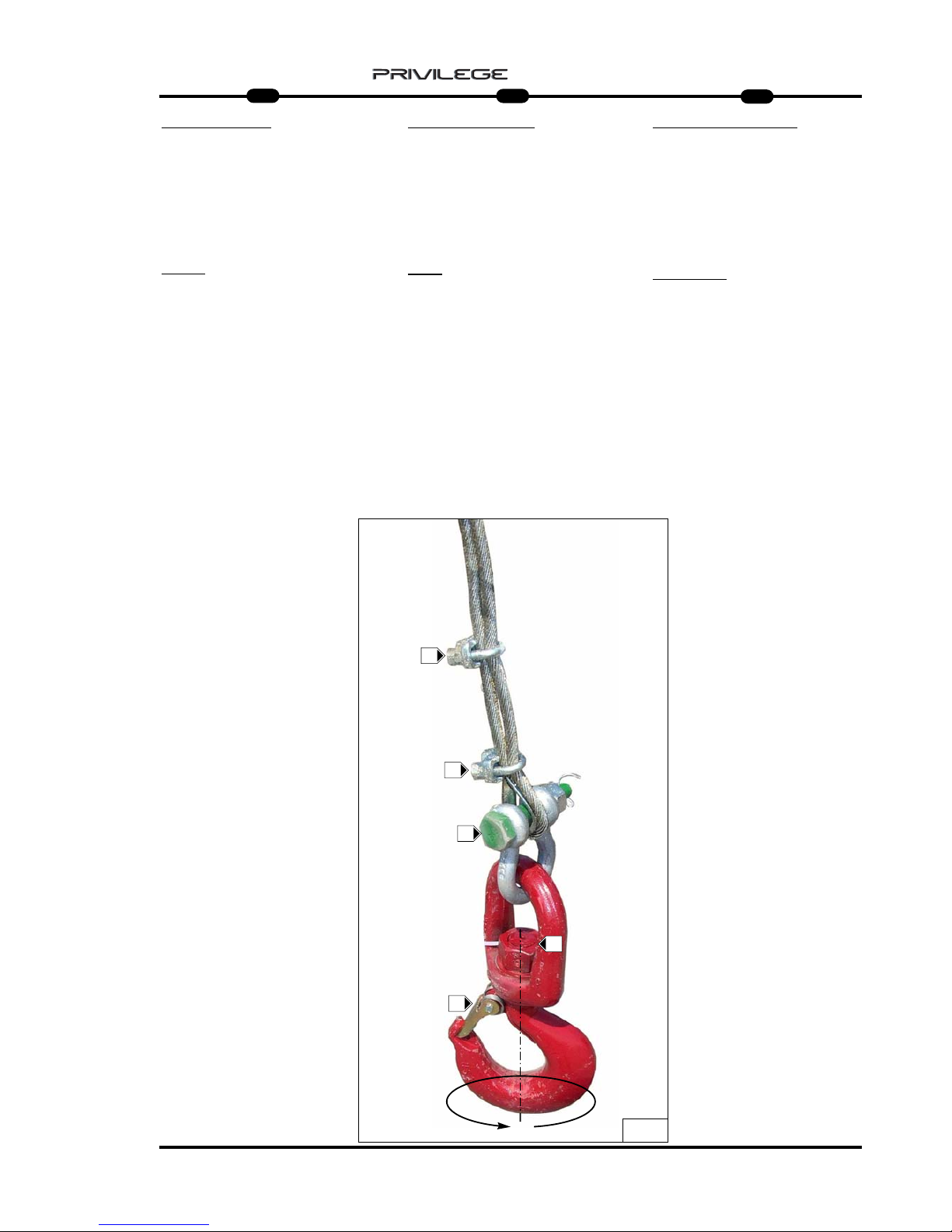
51
IT
EN
DE
5
MRT 1850 - 2150 - 2540
SHACLE AND CLAMPS
It is important to check the condition and
locking of the clamp screws F (Fig.10)
and the shackle G bolt (Fig.10) once a
week.
HOOK
For maximum efficiency, keep the hook
rotation screw N lubricated (Fig.10).
Without load suspended, the hook must
rotate freely, merely by pressing with the
hand P (Fig.10).
Check the condition and working of
safety tab O (Fig.10).
SCHÄKEL
UND KLEMMEN
Es ist wichtig, immer die Schrauben der
Klemmen F (Abb. 10) und des
Schraubbolzens des Schäkels G (Abb.
10) einmal pro Woche auf
Unversehrtheit und festen Sitz zu prüfen.
KRANHAKEN
Für eine maximale Effizienz und
Sicherheit die Rotationsschraube des
Kranhakens N geschmiert halten
(Abb. 10).
Ohne hängende Last muss der
Kranhaken sich immer frei und nur
durch Handdruck drehen P (Abb. 10).
Den Zustand und die Effizienz des
Sicherheitskeils prüfen O (Abb. 10).
GRILLO
e MORSETTI
È importante verificare l’integrità e il serraggio delle viti dei morsetti F (Fig.10) e del
bullone del grillo G (Fig.10) una volta alla
settimana.
GANCIO
Per una massima efficenza mantenere
lubrificata la vite di rotazione del gancio
N (Fig.10).
Senza carico sospeso, il gancio deve
sempre ruotare liberamente e con la sola
pressione della mano P (Fig.10).
Controllare lo stato e l’efficenza della
linguetta di sicurezza O (Fig.10).
10
O
N
F
F
P
G
Page 54

52
IT
EN
DE
5
MRT 1850 - 2150 - 2540
ROPE DESCENT LIMIT STOP (Fig.11)
Keep the piston and hydraulic safety
valve cleaned daily for maximum efficiency; check the unions and pipes to
make sure they are tightened properly.
Check the condition of the descent limit
stop contact leverage and the seal on its
spring.
ROPE LIFT LIMIT ST
OP
Keep the piston and hydraulic safety
valve cleaned daily for maximum efficiency; check the unions and pipes to
make sure they are tightened properly.
Also check the condition of the descent
limit stop contact leverage and the seal
on its spring. (Fig.12)
HYDRAULIC SYSTEM
(Fig.13)
Inspect the unions, valves, pipes daily to
prevent oil leakage which will affect the
working and life of the winch.
ENDSCHAL
TER SEIL SENKEN (Abb. 11)
Für die maximale Effizienz den Kolben und
das hydraulische Sicherheitsventil täglich reinigen. Den Anschluss der Verbindungen und
den Zustand der Leitungen prüfen.
Außerdem das Kontaktgestänge des
Endschalters für Seilsenken auf
Unversehrtheit und die Funktionstüchtigkeit
seiner Feder prüfen.
ENDSCHALTER SEIL HEBEN
Für die maximale Effizienz den Kolben und
das hydraulische Sicherheitsventil täglich reinigen. Den Anschluss der Verbindungen und
den Zustand der Leitungen prüfen.
Außerdem das Kontaktgestänge des
Endschalters für Seilheben auf Unversehrtheit
und die Funktionstüchtigkeit seiner Feder prüfen. (Abb. 12)
HYDRAULISCHE
ANLAGE
(Abb. 13)
Anschlüsse, Ventile, Leitungen täglich prüfen,
um etwaige Leckstellen zu vermeiden, welche
die Leistung und die Haltbarkeit der Winde in
Frage stellen.
FINE CORSA
DISCESA FUNE (Fig.11)
Giornalmente per una massima efficenza
mantenere sempre pulito il pistoncino e la
valvola idraulica di sicurezza; controllare il
serraggio dei raccordi e lo stato dei tubi .
Inoltre verificare l’integrità del leveraggio di
contatto finecorsa discesa e la tenuta della
sua molla.
FINE CORSA
SALIT
A FUNE
Giornalmente per una massima efficenza
mantenere sempre pulito il pistoncino e la
valvola idraulica di sicurezza; controllare il
serraggio dei raccordi e lo stato dei tubi .
Inoltre verificare l’integrità del leveraggio di
contatto finecorsa discesa e la tenuta della
sua molla. (Fig.12)
IMPIANTO
IDRAULICO
(Fig.13)
Ispezionare giornalmente raccordi, valvole,
tubi, per evitare eventuali perdite di olio
che comprommettano il rendimento e la
durata dell’argano.
13
11
12
Page 55

53
IT
EN
DE
5
MRT 1850 - 2150 - 2540
R
I.R. (1) I.R. (2)
0.80 mm
0.80 mm
M
F
N.A.
A
S
250 bar
C1 C2 D
C3
V2
C4
C5
V1 C6
A1
3mm
0.50 mm
Pt 600 = 185 bar
Pt 1200= 180 bar
Pt 1000= 150 bar
HHHHYYYYDDDDRRRRAAAAUUUULLLLIIIICCCC SSSSCCCCHHHHEEEEMMMMEE
EE
A = WINCH
N.A. = MAXIMUM DESCENT
MICROSWITCH
R = OIL TANK
I.R.1 = QUICK-RELEASE COUPLING
I.R.2 = QUICK-RELEASE COUPLING
A1 = MAXIMUM ASCENT
MICROSWITCH
S = VALVE
N = MAXIMUM PRESSURE VALVE
M = MOTOR
F = BRAKE
SSSSCCCCHHHHEEEEMMMMAAAA HHHHYYYYDDDDRRRRAAAAUUUULLLLIIIIKK
KK
A = STEHENDE WINDE
N.A. = MIKROSCHALTER MAXIMALE
SENKUNG
R = ÖLBEHÄLTER
I.R.1 = SCHNELLKUPPLUNG
I.R.2 = SCHNELLKUPPLUNG
A1 = MIKROSCHALTER MAXIMALE
HEBUNG
S = VENTIL
N = ÜBERDRUCKVENTIL
M = MOTOR
F = BREMSE
SSSSCCCCHHHHEEEEMMMMAAAA IIIIDDDDRRRRAAAAUUUULLLLIIIICCCCOO
OO
A = ARGANO
N.A. = MICRO MASSIMA
DISCESA
R = SERBATOIO OLIO
I.R.1 = INNESTO RAPIDO
I.R.2 = INNESTO RAPIDO
A1 = MICRO MASSIMA
SALITA
S = VALVOLA
N = VALVOLA MASSIMA
PRESSIONE
M = MOTORE
F = FRENO
Page 56
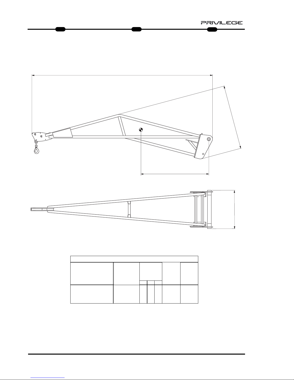
54
IT
EN
DE
5
MRT 1850 - 2150 - 2540
HOIST P 1000 P 1000 ANGRIFFSSCHENRELBRACCETTO P 1000
B
D
C
A
CARATTERISTICHE - CHARACTERISTICS - DATEN
DESCRIZIONE
DESIGNATION
BESCHREIBUNG
MIS. INGOMBRO
OVERAL LENGTH
ABMESSUNGEN
(mm)
ACCESSORIO
ATTACHMENT
ZUBEHOER
D
PESO
WEIGHT
GEWITCH
P 1000
1000 Kg
1200 mm
190 Kg
CAPACITA’
CAPACITY
KAPAZITAET
A B
C
830
815
4027
Page 57

55
IT
EN
DE
5
MRT 1850 - 2150 - 2540
HOIST WITH WINCH PT 1000
: only for MRT 2540 and 2440 EPS
PT 1000 ANGRIFFSSCHENREL
: only for MRT 2540 and 2440 EPS
BRACCETTO PT 1000
: solo per MRT 2540 e 2440 EPS
B
D
C
A
PT 1000
1000 Kg
IDRAULICO
HYDRAULIC
HYDRAULIK
348 Kg830 815 4027
CARATTERISTICHE - CHARACTERISTICS - DATEN
DESCRIZIONE
DESIGNATION
BESCHREIBUNG
FUNE
ROPES
SEIL
VELOCITA’ GANCIO
TOW SPEED
HAKEN
GESCHWINDIGKEIT
FINE CORSA
UP/DOWN
ENDLAUF
MIS. INGOMBRO
OVERAL LENGTH
ABMESSUNGEN
mm
GANCIO “CE“
HOOK “CE”
HAKEN “CE”
PESO
WEIGHT
GEWITCH
Ø 6 mm
x 46 m
(x 56 m)
23 m/min
PRESSIONE DI
ESERCIZIO
OPERATING
PRESSURE
BETRIEBSDRUCK
A B C
5 T
Ø
AVVOLGIMENTO
PULEGGIA
Ø WINDING
PULLEY
W
ICKEL-Ø
RIEMENSCHEIBE
146 mm
Ø
AVVOLGIMENTO
TAMBURO
Ø WINDING
DRUM
WICKEL-Ø
TROMMEL
201 mm
150 Bar max
CAPACITA’
CAPACITY
KAPAZITAET
D
1200
Page 58

56
IT
EN
DE
5
MRT 1850 - 2150 - 2540
PT 1000
MMMMEEEESSSSSSSSAAAAIIIINNNN SSSSEEEERRRRVVVVIIIIZZZZIIIIOOOO EEEE UUUUTTTTIIIILLLLIIIIZZZZZZZZOO
OO
Per la vostra sicurezza, prima di iniziare
un ciclo di lavoro, attenersi alle
Istruzioni obbligatorie di verifica e
controllo:
- verificare l’integrità della struttura
esterna dell’argano e del braccetto
tralicciato.
- verificare il corretto collegamento
idraulico degli innesti rapidi 1, 2,
Drenaggio e lo stato dei tubi flessibili
(Fig.1);
- controllare il corretto funzionamento
del fine corsa discesa fune H (Fig.2);
- controllare il corretto funzionamento
del fine corsa salita fune L (Fig.2);
2
1
2
H
L
D
1
2
PT 1000
CCCCOOOOMMMMMMMMIIIISSSSSSSSIIIIOOOONNNNIIIINNNNGGGG AAAANNNNDDDD UUUUSSSSEE
EE
For your safety, before starting a work
cycle, follow the compulsory instruc-
tions for inspection and checking:
- check the outer frame of the winch and
the trestle arm.
- ensure correct hydraulic connection of
quick-release couplings 1, 2,
Drainage and the condition of the hose
pipes (Fig.1);
- check the correct working of the rope
descent limit stop H (Fig.2);
- check the correct working of the rope
lift limit stop L (Fig.2);
PT 1000
IIIINNNNBBBBEEEETTTTRRRRIIIIEEEEBBBBNNNNAAAAHHHHMMMMEEEE UUUUNNNN GGGGEEEEBBBBRRRRAAAAUUUUCCCCHH
HH
Bevor Sie einen Arbeitszyklus beginnen,
sollten Sie sich zu Ihrer Sicherheit an
die obligatorischen Prüfvorschriften
halten:
- Die Außenstruktur der Winde und des
Gittermastauslegers auf Unversehrtheit
prüfen.
- Den korrekten hydraulischen Anschluss
der Schnellkupplungen 1, 2, der
Rücklaufleitung und den Zustand der
Schläuche prüfen (Abb. 1).
- Den korrekten Betrieb des Endschalters
Seil senken H prüfen (Abb. 2).
- Den korrekten Betrieb des Endschalters
Seil heben L prüfen (Abb. 2).
Page 59

57
IT
EN
DE
5
MRT 1850 - 2150 - 2540
- controllare lo stato della fune B (Fig.3)e il
corretto avvolgimento sul tamburo
A (Fig.3);
- controllare il corretto movimento
rotazione delle puleggie di
guida fune F1 (Fig.3);
- controllare lo stato del capocorda
C (Fig.3);
- verificare l’integrità del bozzello F (Fig.4)
- verificare lo stato del gancio K (Fig.4):
che non sia deformato, che ruoti
liberamente e che la linguetta di
sicurezza sia efficente K1 (Fig.4);
- controllare l’aggancio del braccetto alla
macchina operatrice J (Fig.5).
Dalla posizione di parcheggio è possibile
sganciare il piede di appoggio e
posizionarlo all’interno del braccetto per
operare senza ulteriori ingombri J1 (Fig.5).
3
A
B
4
5
K1
J1
J
C
F
K
K
F1
- check the condition of the rope B (Fig.3)
and its winding around drum A (Fig.3);
- check the correct movement and
rotation of the rope guide pulleys
F1 (Fig.3);
- check the condition of terminal
C (Fig.3);
- check block F to make sure it is intact
(Fig.4)
- check to make sure the shackle
connecting the rope and hook is
screwed on properly K (Fig.4) and that
terminals K1 (Fig.4) block the rope.
- check the hook: make sure it is not
deformed, that it turns freely and that
the safety tab is efficient G (Fig.4);
- check the hooking of the arm to the
operating machine J (Fig.5).
From the parking position, it is possible
to unhook the supporting feet and position it inside the arm to work without
further impediment J1 (Fig.5).
- Den Zustand des Seils B prüfen (Abb. 3)
und die korrekte Aufwicklung um die
Trommel A prüfen (Abb. 3).
- Die korrekte Seiten- und
Rotationsbewegung der
Seillenkscheibe F1 prüfen (Abb. 3).
- Den Zustand der Kabelschlaufen
C (Abb. 3) prüfen.
- Die Umlenkrolle F auf Unversehrtheit
prüfen (Abb. 4)
- Sicherstellen, dass der
Seilverbindungsschäkel und der
Kranhaken gut eingeschraubt sind
K (Abb. 4) und dass die Klemmen
K1 (Abb. 4) das Seil blockieren.
- Den Zustand des Kranhakens prüfen:
Er darf nicht deformiert sein, muss sich
frei drehen können und der
Sicherheitskeil G muss effizient sein
(Abb. 4).
- Sicherstellen, dass die Winde an der
Arbeitsmaschine J eingerastet ist
(Abb. 5).
Aus der Abstellposition die Winde kann
man den Abstellfuß ausklinken und ihn
innerhalb des Auslegers anordnen, ohne
noch mehr Platz in Anspruch zu
nehmen. J1 (Abb. 5)
Page 60

58
IT
EN
DE
5
MRT 1850 - 2150 - 2540
MMMMAAAANNNNUUUUTTTTEEEENNNNZZZZIIIIOOOONNNNEEEE
- RIDUTT
ORE
- FUNE, PULEGGIA
e CAPOCORDA
- BOZZELLO
- GANCIO
- FINE CORSA
DISCESA FUNE
- FINE CORSA
SALITA FUNE
- IMPIANT
O IDRAULICO
MMMMAAAAIIIINNNNTTTTEEEENNNNAAAANNNNCCCCEEEE
- GEAR REDUCER
- ROPE, PULLEY AND TERMINAL
- BLOCK
- HOOK
- ROPE DESCENT LIMIT ST
OP
- ROPE LIFT LIMIT STOP
- HYDRAULIC SYSTEM
WWWWAAAARRRRTTTTUUUUNNNNGG
GG
- GETRIEBE
- SEIL, RIEMENSCHEIBE UND
SEILSCHLAUFE
- UMLENKROLLE
- KRANHAKEN
- ENDSCHALTER SEIL SENKEN
- ENDSCHALTER SEIL HEBEN
- HYDRAULISCHE ANLAGE
Page 61
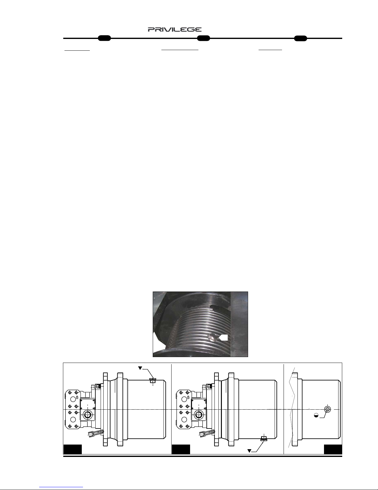
59
IT
EN
DE
5
MRT 1850 - 2150 - 2540
GEAR REDUCER
Correct lubrication will allow efficient
working and long life of the gear r
educer.
The rope must be unwound completely
from the drum to access the level indicator or oil filler plug.
Check the oil level every 100 hours
A (Fig.6b) and top up if necessary
A (Fig.6b) with the same type of oil as
that present in the gear reducer
(SHELL SPIRAX HD80 W90) .
Use of gear oil with EP additives with
viscosity SAE 80W/90 or SAE 85W/140
is recommended.
Oil must be changed the first time
after 150 hours of operation, and subsequently every 1000 hours of operation.
- Change the oil with the gear reducer
still hot so that the oil drains out
completely.
- To drain out the oil, turn the motor
drum so that the filler/drain plug
A (Fig.6a) is downwards.
- Unscrew plug A (Fig.6a) and drain out
the oil completely.
- Turn the drum so that the filler/drain
plug is on the horizontal axis A (Fig.6b).
- Fill with the right type of oil until it
starts flowing out through the level hole
A (Fig.6b).(0,6 lt)
- Refit the plugs and rewind the rope.
GETRIEBE
Die korrekte Schmierung gewährleistet
den guten Betrieb und die lange
Haltbarkeit des Getriebes.
Um Zugriff zum Ölstand- und Öleinfüllstopfen zu erhalten, ist das Seil ganz
von der Trommel abzuwickeln.
Den Ölstand mindestens alle 100
Betriebsstunden prüfen A (Abb. 6b) und
bei Bedarf Öl nachfüllen A (Abb. 6b).
Dazu Öl der gleichen Sorte wie das
verwenden, das im Getriebe
schon vorhanden ist
(SHELL SPIRAX HD80 W90).
Am besten benutzt man Öl für Getriebe
mit EP-Zusatz mit Viskosität
SAE 80W/90 oder SAE 85W/140.
Der erste Ölwechsel ist nach 150
Betriebsstunden fällig, dann jeweils alle
1000 Betriebsstunden.
- Die Ölwechsel bei noch warmen
Getriebe ausführen, um des ganz
auslaufen zu können.
- Um das Öl abzulassen, die Trommel
des Motors drehen, um den Nachfüll/Ablaufstopfen A (Abb. 6a) nach unten
zu bringen.
- Den Stopfen A (Abb. 6a) losschrauben
und das Öl ganz auslaufen lassen.
- Die Trommel drehen, indem man den
Nachfüll-/Ablaufstopofen A nach oben
bringt (Abb. 6).
- Das neue Öl des korrekten Typs
nachfüllen, bis das Öl aus der
Standschraube A ausläuft (Abb. 6b).
- Die Stopfen wieder aufschrauben und
das Seil aufwickeln.
RIDUTT
ORE
Una corretta lubrificazione consente un
buon funzionamento e una lunga durata
del riduttore.
Per accedere all’indicatore di livello o al
tappo di rabbocco olio, occorre srotolare
completamente la fune dal tamburo.
Controllare il livello dell’olio ogni 100 ore
A (Fig.6b) e all’occorrenza
rabboccare A (Fig.6b) con olio dello
stesso tipo di quello presente all’interno del
riduttore (SHELL SPIRAX HD80 W90) .
Si consiglia l’utilizzo di olio per ingranaggi
con addittivazione EP con viscosità SAE
80W/90 oppure SAE 85W/140 .
La prima sostituzione dell’ olio deve
esser effettuata dopo 150 ore di funzionamento, successivamente ogni 1000 ore di
funzionamento.
-Eseguire il cambio dell’olio con riduttore
ancora caldo per facilitare un completo
svuotamento.
- Per scaricare l’olio, ruotare il tamburo del
motore portando il tappo di rabbocco /
scarico A (Fig.6a) verso il basso.
- Svitare il tappo A (Fig.6a) e scaricare
completamente l’olio.
- Ruotare il tamburo portando il foro di
rabbocco/scarico sull’asse orizzontale
A (Fig.6b).
- Rabbocare con olio nuovo e di tipo
corretto fino a quando l’olio non fuoriesce
da foro di livelo A (Fig.6b). (0,6 lt)
- Riavvitare i tappi e riavvolgere la fune.
A
A
A
6a
6
A
6b
Page 62

60
IT
EN
DE
5
MRT 1850 - 2150 - 2540
SEIL, RIEMENSCHEIBE und
SEILSCHLINGE
Täglich prüfen, dass das Seil A (Abb. 7)
immer einen sehr guten Zustand aufweist, dass keine Seilfasern gerissen sind
(Abb. 7a) und dass das Seil gut um die
Trommel B aufgewickelt ist (Abb. 7).
Andernfalls ist das Seil durch ein neues
mit dem gleichen Durchmesser und den
gleichen Eigenschaften zu ersetzen.
Die Schmierung des Seils prüfen. Muss
es geschmiert werden, dazu ein
Industriefett oder ein synthetisches
Staubschutzfett benutzen.
Die Bolzen C (Abb. 8), auf dem sich die
Führungsscheiben D (Abb. 8) drehen,
täglich prüfen und geschmiert halten.
Diese muss sich immer gut drehen.
Falls erforderlich, den Bolzen mit
Lithiumseifenfett schmieren.
Die Seilschlaufe E (Abb. 9) und die
Bügelklemmen auf Unversehrtheit
prüfen.
ROPE, PULLEY
and TERMINAL
Check rope A (Fig.7) daily to make sure
it is good condition, that there are no
broken filaments (Fig.7a) and that it is
wound properly around drum B (Fig.7).
If this is not the case, replace the rope
with a new one having the same diameter and features.
Check the lubrication of the rope, and if,
necessary, lubricate with industrial
grease or Dust-proof synthetic oil.
Check and lubricate pins C (Fig.8) on
which guide pulleys D (Fig.8) rotate,
and these must rotate freely.
If necessary, lubricate the pin with
lithium soap grease.
Check terminal E (Fig.9) and the rope-
holder clamps to make sure they are
intact.
FUNE, PULEGGIA
e CAPOCORDA
Controllare giornalmente che la fune
A (Fig.7) sia sempre in ottimo stato, che
non ci siano filamenti rotti (Fig.7a) e che
sia ben arrotolata sul tamburo B (Fig.7).
Altrimenti sostituirla con una nuova e
dello stesso diametro e caratteristiche.
Controllare la lubrificazione della fune,
se necessita lubrificare con grasso
industriale oppure olio sintetico antipolvere.
Controllare e mantenere lubrificato i
perni C (Fig.8) su cui ruotano le
puleggie di guida D (Fig.8), che
dovranno avere sempre un buono
movimento di rotazione.
Se necessita, lubrificare con grasso al
sapone di litio il perno.
Assicurarsi dell’integrità dei capocorda
E (Fig.9) e dei suoi morsetti fermafune.
9
7
7a
A
B
E
E
8
9
E
C
D
C
D
Page 63
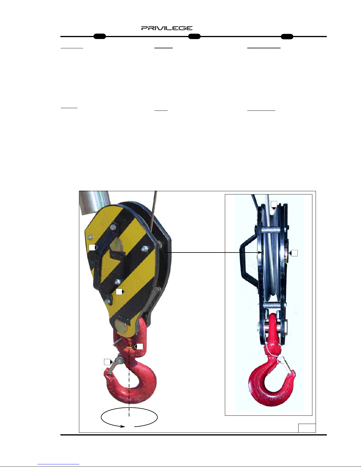
61
IT
EN
DE
5
MRT 1850 - 2150 - 2540
BOZZELLO
Per una massima efficenza e sicurezza,
mantenere intatta la struttura esterna
F (Fig.10) e controllare che la puleggia
G (Fig.10) ruoti correttamente sul suo perno
G1 (Fig.10) .
Se necessità, lubrificare con grasso al
sapone di litio il perno G1 (Fig.10).
GANCIO
Per una massima efficenza mantenere
lubrificata la vite di rotazione del gancio
N (Fig.10).
Senza carico sospeso, il gancio deve
sempre ruotare liberamente e con la sola
pressione della mano P (Fig.10).
Controllare lo stato e l’efficenza della
linguetta di sicurezza O (Fig.10).
G
10
O
N
G1
F
F
P
BLOCK
For maximum efficiency and safety,
make sure the outer frame F (Fig.10) is
intact and check pulley G (Fig.10) to
make sure it rotates properly around its
pin G1 (Fig.10) .
Lubricate pin M with lithium soap grease, if necessary (Fig.10).
HOOK
For maximum efficiency, keep the hook
rotation screw N lubricated (Fig.10).
Without load suspended, the hook must
rotate freely, merely by pressing with the
hand P (Fig.10).
Check the condition and working of
safety tab O (Fig.10).
UMLENKROLLE
Für eine maximale Effizienz und
Sicherheit die Außenstruktur F (Abb. 10)
unversehrt halten und sicherstellen,
dass die Riemenscheibe G (Abb. 10)
sich korrekt um ihren Bolzen G1 dreht
(Abb. 10).
Falls erforderlich, den Bolzen M mit
Lithiumseifenfett schmieren (Abb. 10).
KRANHAKEN
Für eine maximale Effizienz und
Sicherheit die Rotationsschraube des
Kranhakens N geschmiert halten
(Abb. 10).
Ohne hängende Last muss der
Kranhaken sich immer frei und nur
durch Handdruck drehen P (Abb. 10).
Den Zustand und die Effizienz des
Sicherheitskeils prüfen O (Abb. 10).
Page 64

62
IT
EN
DE
5
MRT 1850 - 2150 - 2540
FINE CORSA DISCESA FUNE (Fig.11)
Giornalmente per una massima efficenza
mantenere sempre pulito il pistoncino e la
valvola idraulica di sicurezza; controllare il
serraggio dei raccordi e lo stato dei tubi.
Inoltre verificare l’integrità del leveraggio di
contatto finecorsa discesa e la tenuta della
sua molla.
FINE CORSA
SALITA
FUNE
Giornalmente per una massima efficenza
mantenere sempre pulito il pistoncino e la
valvola idraulica di sicurezza; controllare il
serraggio dei raccordi e lo stato dei tubi .
Inoltre verificare l’integrità del leveraggio di
contatto finecorsa discesa e la tenuta della
sua molla. (Fig.12)
IMPIANTO IDRAULICO (Fig.13)
Ispezionare giornalmente raccordi, valvole,
tubi, per evitare eventuali perdite di olio
che comprommettano il rendimento e la
durata dell’argano.
11
12
13
ROPE DESCENT LIMIT STOP (Fig.11)
Keep the piston and hydraulic safety
valve cleaned daily for maximum efficiency; check the unions and pipes to
make sure they are tightened properly.
Check the condition of the descent limit
stop contact leverage and the seal on its
spring.
ROPE LIFT LIMIT ST
OP
Keep the piston and hydraulic safety
valve cleaned daily for maximum efficiency; check the unions and pipes to
make sure they are tightened properly.
Also check the condition of the descent
limit stop contact leverage and the seal
on its spring. (Fig.12)
HYDRAULIC SYSTEM
(Fig.13)
Inspect the unions, valves, pipes daily to
prevent oil leakage which will affect the
working and life of the winch.
ENDSCHAL
TER SEIL SENKEN (Abb. 11)
Für die maximale Effizienz den Kolben und
das hydraulische Sicherheitsventil täglich reinigen. Den Anschluss der Verbindungen und
den Zustand der Leitungen prüfen.
Außerdem das Kontaktgestänge des
Endschalters für Seilsenken auf
Unversehrtheit und die Funktionstüchtigkeit
seiner Feder prüfen.
ENDSCHAL
TER SEIL HEBEN
Für die maximale Effizienz den Kolben und
das hydraulische Sicherheitsventil täglich reinigen. Den Anschluss der Verbindungen und
den Zustand der Leitungen prüfen.
Außerdem das Kontaktgestänge des
Endschalters für Seilheben auf Unversehrtheit
und die Funktionstüchtigkeit seiner Feder prüfen. (Abb. 12)
HYDRAULISCHE ANLAGE (Abb. 13)
Anschlüsse, Ventile, Leitungen täglich prüfen,
um etwaige Leckstellen zu vermeiden, welche
die Leistung und die Haltbarkeit der Winde in
Frage stellen.
Page 65
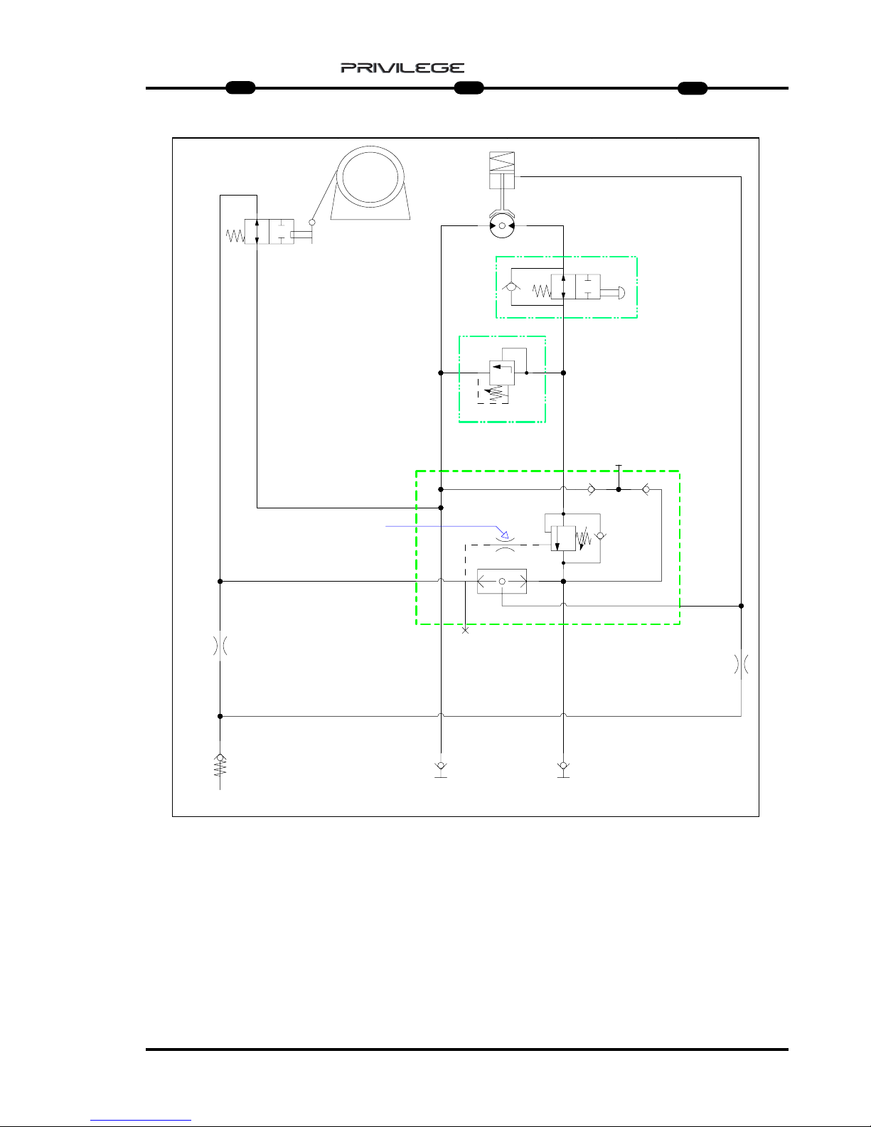
63
IT
EN
DE
5
MRT 1850 - 2150 - 2540
R
I.R. (1) I.R. (2)
0.80 mm
0.80 mm
M
F
N.A.
A
S
250 bar
C1 C2 D
C3
V2
C4
C5
V1 C6
A1
3mm
0.50 mm
Pt 600 = 185 bar
Pt 1200= 180 bar
Pt 1000= 150 bar
HHHHYYYYDDDDRRRRAAAAUUUULLLLIIIICCCC SSSSCCCCHHHHEEEEMMMMEE
EE
A = WINCH
N.A. = MAXIMUM DESCENT
MICROSWITCH
R = OIL TANK
I.R.1 = QUICK-RELEASE COUPLING
I.R.2 = QUICK-RELEASE COUPLING
A1 = MAXIMUM ASCENT
MICROSWITCH
S = VALVE
N = MAXIMUM PRESSURE VALVE
M = MOTOR
F = BRAKE
SSSSCCCCHHHHEEEEMMMMAAAA HHHHYYYYDDDDRRRRAAAAUUUULLLLIIIIKK
KK
A = STEHENDE WINDE
N.A. = MIKROSCHALTER MAXIMALE
SENKUNG
R = ÖLBEHÄLTER
I.R.1 = SCHNELLKUPPLUNG
I.R.2 = SCHNELLKUPPLUNG
A1 = MIKROSCHALTER MAXIMALE
HEBUNG
S = VENTIL
N = ÜBERDRUCKVENTIL
M = MOTOR
F = BREMSE
SSSSCCCCHHHHEEEEMMMMAAAA IIIIDDDDRRRRAAAAUUUULLLLIIIICCCCOO
OO
A = ARGANO
N.A. = MICRO MASSIMA
DISCESA
R = SERBATOIO OLIO
I.R.1 = INNESTO RAPIDO
I.R.2 = INNESTO RAPIDO
A1 = MICRO MASSIMA
SALITA
S = VALVOLA
N = VALVOLA MASSIMA
PRESSIONE
M = MOTORE
F = FRENO
Page 66

64
IT
EN
DE
5
MRT 1850 - 2150 - 2540
HOIST P 1200 P 1200 ANGRIFFSSCHENRELBRACCETTO P 1200
C
B
D
A
CARATTERISTICHE - CHARACTERISTICS - DATEN
DESCRIZIONE
DESIGNATION
BESCHREIBUNG
MIS. INGOMBRO
OVERAL
LENGTH
ABMESSUNGEN
(mm)
ACCESSORIO
ATTACHMENT
ZUBEHOER
D
PESO
WEIGHT
GEWITCH
P 1200
1200 Kg
1000 mm 200 Kg
CAPACITA’
CAPACITY
KAPAZITAET
A B C
830 868 2944
Page 67

65
IT
EN
DE
5
MRT 1850 - 2150 - 2540
HOIST WITH WINCH PT 1200
: Only for MRT 2540 and 2440 EPS
PT 1200 ANGRIFFSSCHENREL
: Only for MRT 2540 and 2440 EPS
BRACCETTO PT 1200
: solo per MRT 2540 e 2440 EPS
B
D
C
A
PT 1200
1200 Kg
IDRAULICO
HYDRAULIC
HYDRAULIK
310 Kg830 868 2944
CARATTERISTICHE - CHARACTERISTICS - DATEN
DESCRIZIONE
DESIGNATION
BESCHREIBUNG
FUNE
ROPES
SEIL
VELOCITA’ GANCIO
TOW SPEED
HAKEN
GESCHWINDIGKEIT
FINE CORSA
UP/DOWN
ENDLAUF
MIS. INGOMBRO
OVERAL LENGTH
ABMESSUNGEN
mm
GANCIO “CE“
HOOK “CE”
HAKEN “CE”
PESO
WEIGHT
GEWITCH
Ø 6 mm
x 46 m
(x 56 m)
23 m/min
PRESSIONE DI
ESERCIZIO
OPERATING
PRESSURE
BETRIEB-
SDRUCK
A B C
5 T
Ø
AVVOLGIMENTO
PULEGGIA
Ø WINDING
PULLEY
WICKEL-Ø
RIEMENSCHEIBE
146 mm
Ø
AVVOLGIMENTO
TAMBURO
Ø WINDING
DRUM
WICKEL-Ø
TROMMEL
201 mm
180 Bar max
CAPACITA’
CAPACITY
KAPAZITAET
D
800
Page 68

66
IT
EN
DE
5
MRT 1850 - 2150 - 2540
PT 1200
MMMMEEEESSSSSSSSAAAAIIIINNNN SSSSEEEERRRRVVVVIIIIZZZZIIIIOOOO EEEE UUUUTTTTIIIILLLLIIIIZZZZZZZZOO
OO
Per la vostra sicurezza, prima di iniziare
un ciclo di lavoro, attenersi alle
Istruzioni obbligatorie di verifica e
controllo:
- verificare l’integrità della struttura
esterna dell’argano e del braccetto
tralicciato.
- verificare il corretto collegamento
idraulico degli innesti rapidi 1, 2,
Drenaggio e lo stato dei tubi flessibili
(Fig.1);
- controllare il corretto funzionamento
del fine corsa discesa fune H (Fig.2);
- controllare il corretto funzionamento
del fine corsa salita fune L (Fig.2);
2
1
2
H
L
D
1
2
PT 1200
CCCCOOOOMMMMMMMMIIIISSSSSSSSIIIIOOOONNNNIIIINNNNGGGG AAAANNNNDDDD UUUUSSSSEE
EE
For your safety, before starting a work
cycle, follow the compulsory instruc-
tions for inspection and checking:
- check the outer frame of the winch and
the trestle arm.
- ensure correct hydraulic connection of
quick-release couplings 1, 2,
Drainage and the condition of the hose
pipes (Fig.1);
- check the correct working of the rope
descent limit stop H (Fig.2);
- check the correct working of the rope
lift limit stop L (Fig.2);
PT 1200
IIIINNNNBBBBEEEETTTTRRRRIIIIEEEEBBBBNNNNAAAAHHHHMMMMEEEE UUUUNNNN GGGGEEEEBBBBRRRRAAAAUUUUCCCCHH
HH
Bevor Sie einen Arbeitszyklus beginnen,
sollten Sie sich zu Ihrer Sicherheit an
die obligatorischen Prüfvorschriften
halten:
- Die Außenstruktur der Winde und des
Gittermastauslegers auf Unversehrtheit
prüfen.
- Den korrekten hydraulischen Anschluss
der Schnellkupplungen 1, 2, der
Rücklaufleitung und den Zustand der
Schläuche prüfen (Abb. 1).
- Den korrekten Betrieb des Endschalters
Seil senken H prüfen (Abb. 2).
- Den korrekten Betrieb des Endschalters
Seil heben L prüfen (Abb. 2).
Page 69

67
IT
EN
DE
5
MRT 1850 - 2150 - 2540
3
A
B
4
5
K1
J1
J
C
F
K
K
F1
- controllare lo stato della fune B (Fig.3)e il
corretto avvolgimento sul tamburo
A (Fig.3);
- controllare il corretto movimento
rotazione delle puleggie di
guida fune F1 (Fig.3);
- controllare lo stato del capocorda
C (Fig.3);
- verificare l’integrità del bozzello F (Fig.4)
- verificare lo stato del gancio K (Fig.4):
che non sia deformato, che ruoti
liberamente e che la linguetta di
sicurezza sia efficente K1 (Fig.4);
- controllare l’aggancio del braccetto alla
macchina operatrice J (Fig.5).
Dalla posizione di parcheggio è possibile
sganciare il piede di appoggio e
posizionarlo all’interno del braccetto per
operare senza ulteriori ingombri J1 (Fig.5).
- check the condition of the rope B (Fig.3)
and its winding around drum A (Fig.3);
- check the correct movement and
rotation of the rope guide pulleys
F1 (Fig.3);
- check the condition of terminal
C (Fig.3);
- check block F to make sure it is intact
(Fig.4)
- check to make sure the shackle
connecting the rope and hook is
screwed on properly K (Fig.4) and that
terminals K1 (Fig.4) block the rope.
- check the hook: make sure it is not
deformed, that it turns freely and that
the safety tab is efficient G (Fig.4);
- check the hooking of the arm to the
operating machine J (Fig.5).
From the parking position, it is possible
to unhook the supporting feet and position it inside the arm to work without
further impediment J1 (Fig.5).
- Den Zustand des Seils B prüfen (Abb. 3)
und die korrekte Aufwicklung um die
Trommel A prüfen (Abb. 3).
- Die korrekte Seiten- und
Rotationsbewegung der
Seillenkscheibe F1 prüfen (Abb. 3).
- Den Zustand der Kabelschlaufen
C (Abb. 3) prüfen.
- Die Umlenkrolle F auf Unversehrtheit
prüfen (Abb. 4)
- Sicherstellen, dass der
Seilverbindungsschäkel und der
Kranhaken gut eingeschraubt sind
K (Abb. 4) und dass die Klemmen
K1 (Abb. 4) das Seil blockieren.
- Den Zustand des Kranhakens prüfen:
Er darf nicht deformiert sein, muss sich
frei drehen können und der
Sicherheitskeil G muss effizient sein
(Abb. 4).
- Sicherstellen, dass die Winde an der
Arbeitsmaschine J eingerastet ist
(Abb. 5).
Aus der Abstellposition die Winde kann
man den Abstellfuß ausklinken und ihn
innerhalb des Auslegers anordnen, ohne
noch mehr Platz in Anspruch zu
nehmen. J1 (Abb. 5)
Page 70

68
IT
EN
DE
5
MRT 1850 - 2150 - 2540
MMMMAAAANNNNUUUUTTTTEEEENNNNZZZZIIIIOOOONNNNEEEE
- RIDUTTORE
- FUNE, PULEGGIA e CAPOCORDA
- BOZZELLO
- GANCIO
- FINE CORSA DISCESA FUNE
- FINE CORSA
SALITA FUNE
- IMPIANTO IDRAULICO
MMMMAAAAIIIINNNNTTTTEEEENNNNAAAANNNNCCCCEEEE
- GEAR REDUCER
- ROPE, PULLEY AND TERMINAL
- BLOCK
- HOOK
- ROPE DESCENT LIMIT ST
OP
- ROPE LIFT LIMIT STOP
- HYDRAULIC SYSTEM
WWWWAAAARRRRTTTTUUUUNNNNGG
GG
- GETRIEBE
- SEIL, RIEMENSCHEIBE UND
SEILSCHLAUFE
- UMLENKROLLE
- KRANHAKEN
- ENDSCHAL
TER SEIL SENKEN
- ENDSCHALTER SEIL
HEBEN
- HYDRAULISCHE
ANLAGE
Page 71

69
IT
EN
DE
5
MRT 1850 - 2150 - 2540
RIDUTTORE
Una corretta lubrificazione consente un
buon funzionamento e una lunga durata
del riduttore.
Per accedere all’indicatore di livello o al
tappo di rabbocco olio, occorre srotolare
completamente la fune dal tamburo.
Controllare il livello dell’olio ogni 100 ore
A (Fig.6b) e all’occorrenza
rabboccare A (Fig.6b) con olio dello
stesso tipo di quello presente all’interno del
riduttore (SHELL SPIRAX HD80 W90) .
Si consiglia l’utilizzo di olio per ingranaggi
con addittivazione EP con viscosità SAE
80W/90 oppure SAE 85W/140 .
La prima sostituzione dell’ olio deve
esser effettuata dopo 150 ore di funzionamento, successivamente ogni 1000 ore di
funzionamento.
-Eseguire il cambio dell’olio con riduttore
ancora caldo per facilitare un completo
svuotamento.
- Per scaricare l’olio, ruotare il tamburo del
motore portando il tappo di rabbocco /
scarico A (Fig.6a) verso il basso.
- Svitare il tappo A (Fig.6a) e scaricare
completamente l’olio.
- Ruotare il tamburo portando il foro di
rabbocco/scarico sull’asse orizzontale
A (Fig.6b).
- Rabbocare con olio nuovo e di tipo
corretto fino a quando l’olio non fuoriesce
da foro di livelo A (Fig.6b). (0,6 lt)
- Riavvitare i tappi e riavvolgere la fune.
A
A
A
6a
6
A
6b
GEAR REDUCER
Correct lubrication will allow efficient
working and long life of the gear r
educer.
The rope must be unwound completely
from the drum to access the level indicator or oil filler plug.
Check the oil level every 100 hours
A (Fig.6b) and top up if necessary
A (Fig.6b) with the same type of oil as
that present in the gear reducer
(SHELL SPIRAX HD80 W90) .
Use of gear oil with EP additives with
viscosity SAE 80W/90 or SAE 85W/140
is recommended.
Oil must be changed the first time
after 150 hours of operation, and subsequently every 1000 hours of operation.
- Change the oil with the gear reducer
still hot so that the oil drains out
completely.
- To drain out the oil, turn the motor
drum so that the filler/drain plug
A (Fig.6a) is downwards.
- Unscrew plug A (Fig.6a) and drain out
the oil completely.
- Turn the drum so that the filler/drain
plug is on the horizontal axis A (Fig.6b).
- Fill with the right type of oil until it
starts flowing out through the level hole
A (Fig.6b).(0,6 lt)
- Refit the plugs and rewind the rope.
GETRIEBE
Die korrekte Schmierung gewährleistet
den guten Betrieb und die lange
Haltbarkeit des Getriebes.
Um Zugriff zum Ölstand- und Öleinfüllstopfen zu erhalten, ist das Seil ganz
von der Trommel abzuwickeln.
Den Ölstand mindestens alle 100
Betriebsstunden prüfen A (Abb. 6b) und
bei Bedarf Öl nachfüllen A (Abb. 6b).
Dazu Öl der gleichen Sorte wie das
verwenden, das im Getriebe
schon vorhanden ist
(SHELL SPIRAX HD80 W90).
Am besten benutzt man Öl für Getriebe
mit EP-Zusatz mit Viskosität
SAE 80W/90 oder SAE 85W/140.
Der erste Ölwechsel ist nach 150
Betriebsstunden fällig, dann jeweils alle
1000 Betriebsstunden.
- Die Ölwechsel bei noch warmen
Getriebe ausführen, um des ganz
auslaufen zu können.
- Um das Öl abzulassen, die Trommel
des Motors drehen, um den Nachfüll/Ablaufstopfen A (Abb. 6a) nach unten
zu bringen.
- Den Stopfen A (Abb. 6a) losschrauben
und das Öl ganz auslaufen lassen.
- Die Trommel drehen, indem man den
Nachfüll-/Ablaufstopofen A nach oben
bringt (Abb. 6).
- Das neue Öl des korrekten Typs
nachfüllen, bis das Öl aus der
Standschraube A ausläuft
(Abb. 6b).(0,6 lt)
- Die Stopfen wieder aufschrauben und
das Seil aufwickeln.
Page 72

70
IT
EN
DE
5
MRT 1850 - 2150 - 2540
FUNE, PULEGGIA e CAPOCORDA
Controllare giornalmente che la fune
A (Fig.7) sia sempre in ottimo stato, che
non ci siano filamenti rotti (Fig.7a) e che
sia ben arrotolata sul tamburo B (Fig.7).
Altrimenti sostituirla con una nuova e
dello stesso diametro e caratteristiche.
Controllare la lubrificazione della fune,
se necessita lubrificare con grasso
industriale oppure olio sintetico antipolvere.
Controllare e mantenere lubrificato i
perni C (Fig.8) su cui ruotano le
puleggie di guida D (Fig.8), che
dovranno avere sempre un buono
movimento di rotazione.
Se necessita, lubrificare con grasso al
sapone di litio il perno.
Assicurarsi dell’integrità dei capocorda
E (Fig.9) e dei suoi morsetti fermafune.
9
7
7a
A
B
E
E
8
9
E
C
D
C
D
SEIL, RIEMENSCHEIBE und
SEILSCHLINGE
Täglich prüfen, dass das Seil A (Abb. 7)
immer einen sehr guten Zustand aufweist, dass keine Seilfasern gerissen sind
(Abb. 7a) und dass das Seil gut um die
Trommel B aufgewickelt ist (Abb. 7).
Andernfalls ist das Seil durch ein neues
mit dem gleichen Durchmesser und den
gleichen Eigenschaften zu ersetzen.
Die Schmierung des Seils prüfen. Muss
es geschmiert werden, dazu ein
Industriefett oder ein synthetisches
Staubschutzfett benutzen.
Die Bolzen C (Abb. 8), auf dem sich die
Führungsscheiben D (Abb. 8) drehen,
täglich prüfen und geschmiert halten.
Diese muss sich immer gut drehen.
Falls erforderlich, den Bolzen mit
Lithiumseifenfett schmieren.
Die Seilschlaufe E (Abb. 9) und die
Bügelklemmen auf Unversehrtheit
prüfen.
ROPE, PULLEY
and TERMINAL
Check rope A (Fig.7) daily to make sure
it is good condition, that there are no
broken filaments (Fig.7a) and that it is
wound properly around drum B (Fig.7).
If this is not the case, replace the rope
with a new one having the same diameter and features.
Check the lubrication of the rope, and if,
necessary, lubricate with industrial
grease or Dust-proof synthetic oil.
Check and lubricate pins C (Fig.8) on
which guide pulleys D (Fig.8) rotate,
and these must rotate freely.
If necessary, lubricate the pin with
lithium soap grease.
Check terminal E (Fig.9) and the rope-
holder clamps to make sure they are
intact.
Page 73

71
IT
EN
DE
5
MRT 1850 - 2150 - 2540
BOZZELLO
Per una massima efficenza e sicurezza,
mantenere intatta la struttura esterna
F (Fig.10) e controllare che la puleggia
G (Fig.10) ruoti correttamente sul suo perno
G1 (Fig.10) .
Se necessità, lubrificare con grasso al
sapone di litio il perno G1 (Fig.10).
GANCIO
Per una massima efficenza mantenere
lubrificata la vite di rotazione del gancio
N (Fig.10).
Senza carico sospeso, il gancio deve
sempre ruotare liberamente e con la sola
pressione della mano P (Fig.10).
Controllare lo stato e l’efficenza della
linguetta di sicurezza O (Fig.10).
G
10
O
N
G1
F
F
P
BLOCK
For maximum efficiency and safety,
make sure the outer frame F (Fig.10) is
intact and check pulley G (Fig.10) to
make sure it rotates properly around its
pin G1 (Fig.10) .
Lubricate pin M with lithium soap grease, if necessary (Fig.10).
HOOK
For maximum efficiency, keep the hook
rotation screw N lubricated (Fig.10).
Without load suspended, the hook must
rotate freely, merely by pressing with the
hand P (Fig.10).
Check the condition and working of
safety tab O (Fig.10).
UMLENKROLLE
Für eine maximale Effizienz und
Sicherheit die Außenstruktur F (Abb. 10)
unversehrt halten und sicherstellen,
dass die Riemenscheibe G (Abb. 10)
sich korrekt um ihren Bolzen G1 dreht
(Abb. 10).
Falls erforderlich, den Bolzen M mit
Lithiumseifenfett schmieren (Abb. 10).
KRANHAKEN
Für eine maximale Effizienz und
Sicherheit die Rotationsschraube des
Kranhakens N geschmiert halten
(Abb. 10).
Ohne hängende Last muss der
Kranhaken sich immer frei und nur
durch Handdruck drehen P (Abb. 10).
Den Zustand und die Effizienz des
Sicherheitskeils prüfen O (Abb. 10).
Page 74

72
IT
EN
DE
5
MRT 1850 - 2150 - 2540
FINE CORSA DISCESA FUNE (Fig.11)
Giornalmente per una massima efficenza
mantenere sempre pulito il pistoncino e la
valvola idraulica di sicurezza; controllare il
serraggio dei raccordi e lo stato dei tubi.
Inoltre verificare l’integrità del leveraggio di
contatto finecorsa discesa e la tenuta della
sua molla.
FINE CORSA
SALITA FUNE
Giornalmente per una massima efficenza
mantenere sempre pulito il pistoncino e la
valvola idraulica di sicurezza; controllare il
serraggio dei raccordi e lo stato dei tubi .
Inoltre verificare l’integrità del leveraggio di
contatto finecorsa discesa e la tenuta della
sua molla. (Fig.12)
IMPIANTO
IDRAULICO
(Fig.13)
Ispezionare giornalmente raccordi, valvole,
tubi, per evitare eventuali perdite di olio
che comprommettano il rendimento e la
durata dell’argano.
11
12
13
ROPE DESCENT LIMIT STOP (Fig.11)
Keep the piston and hydraulic safety
valve cleaned daily for maximum efficiency; check the unions and pipes to
make sure they are tightened properly.
Check the condition of the descent limit
stop contact leverage and the seal on its
spring.
ROPE LIFT LIMIT ST
OP
Keep the piston and hydraulic safety
valve cleaned daily for maximum efficiency; check the unions and pipes to
make sure they are tightened properly.
Also check the condition of the descent
limit stop contact leverage and the seal
on its spring. (Fig.12)
HYDRAULIC SYSTEM
(Fig.13)
Inspect the unions, valves, pipes daily to
prevent oil leakage which will affect the
working and life of the winch.
ENDSCHAL
TER SEIL SENKEN (Abb. 11)
Für die maximale Effizienz den Kolben und
das hydraulische Sicherheitsventil täglich reinigen. Den Anschluss der Verbindungen und
den Zustand der Leitungen prüfen.
Außerdem das Kontaktgestänge des
Endschalters für Seilsenken auf
Unversehrtheit und die Funktionstüchtigkeit
seiner Feder prüfen.
ENDSCHAL
TER SEIL HEBEN
Für die maximale Effizienz den Kolben und
das hydraulische Sicherheitsventil täglich reinigen. Den Anschluss der Verbindungen und
den Zustand der Leitungen prüfen.
Außerdem das Kontaktgestänge des
Endschalters für Seilheben auf Unversehrtheit
und die Funktionstüchtigkeit seiner Feder prüfen. (Abb. 12)
HYDRAULISCHE
ANLAGE (Abb. 13)
Anschlüsse, Ventile, Leitungen täglich prüfen,
um etwaige Leckstellen zu vermeiden, welche
die Leistung und die Haltbarkeit der Winde in
Frage stellen.
Page 75

73
IT
EN
DE
5
MRT 1850 - 2150 - 2540
R
I.R. (1) I.R. (2)
0.80 mm
0.80 mm
M
F
N.A.
A
S
250 bar
C1 C2 D
C3
V2
C4
C5
V1 C6
A1
3mm
0.50 mm
Pt 600 = 185 bar
Pt 1200= 180 bar
Pt 1000= 150 bar
HHHHYYYYDDDDRRRRAAAAUUUULLLLIIIICCCC SSSSCCCCHHHHEEEEMMMMEE
EE
A = WINCH
N.A. = MAXIMUM DESCENT
MICROSWITCH
R = OIL TANK
I.R.1 = QUICK-RELEASE COUPLING
I.R.2 = QUICK-RELEASE COUPLING
A1 = MAXIMUM ASCENT
MICROSWITCH
S = VALVE
N = MAXIMUM PRESSURE VALVE
M = MOTOR
F = BRAKE
SSSSCCCCHHHHEEEEMMMMAAAA HHHHYYYYDDDDRRRRAAAAUUUULLLLIIIIKK
KK
A = STEHENDE WINDE
N.A. = MIKROSCHALTER MAXIMALE
SENKUNG
R = ÖLBEHÄLTER
I.R.1 = SCHNELLKUPPLUNG
I.R.2 = SCHNELLKUPPLUNG
A1 = MIKROSCHALTER MAXIMALE
HEBUNG
S = VENTIL
N = ÜBERDRUCKVENTIL
M = MOTOR
F = BREMSE
SSSSCCCCHHHHEEEEMMMMAAAA IIIIDDDDRRRRAAAAUUUULLLLIIIICCCCOO
OO
A = ARGANO
N.A. = MICRO MASSIMA
DISCESA
R = SERBATOIO OLIO
I.R.1 = INNESTO RAPIDO
I.R.2 = INNESTO RAPIDO
A1 = MICRO MASSIMA
SALITA
S = VALVOLA
N = VALVOLA MASSIMA
PRESSIONE
M = MOTORE
F = FRENO
Page 76
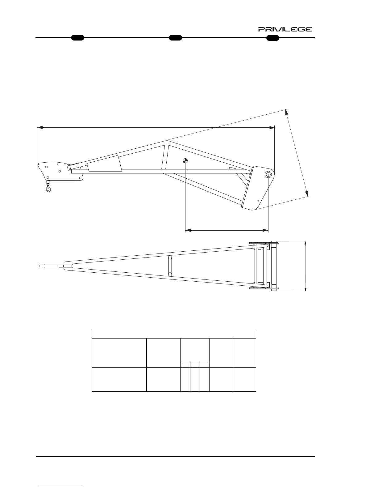
74
IT
EN
DE
5
MRT 1850 - 2150 - 2540
HOIST P 1500 P 1500 ANGRIFFSSCHENRELBRACCETTO P 1500
CARATTERISTICHE - CHARACTERISTICS - DATEN
DESCRIZIONE
DESIGNATION
BESCHREIBUNG
MIS. INGOMBRO
OVERAL
LENGTH
ABMESSUNGEN
(mm)
ACCESSORIO
ATTACHMENT
ZUBEHOER
D
PESO
WEIGHT
GEWITCH
P 1500
1500 Kg
1000 mm 170 Kg
CAPACITA’
CAPACITY
KAPAZITAET
A B C
830 815 4027
C
B
D
A
Page 77

75
IT
EN
DE
5
MRT 1850 - 2150 - 2540
PT 1500 ANGRIFFSSCHENREL
: only for MRT 2540 and 2440 EPS
HOIST WITH WINCH PT 1500
: only for MRT 2540 and 2440 EPS
B
D
C
A
BRACCETTO PT 1500
: solo per MRT 2540 e 2440 EPS
PT 1500
1500 Kg
IDRAULICO
HYDRAULIC
HYDRAULIK
363 Kg830 868 2944
CARATTERISTICHE - CHARACTERISTICS - DATEN
DESCRIZIONE
DESIGNATION
BESCHREIBUNG
FUNE
ROPES
SEIL
VELOCITA’ GANCIO
TOW SPEED
HAKEN
GESCHWINDIGKEIT
FINE CORSA
UP/DOWN
ENDLAUF
MIS. INGOMBRO
OVERAL LENGTH
ABMESSUNGEN
mm
GANCIO “CE“
HOOK “CE”
HAKEN “CE”
PESO
WEIGHT
GEWITCH
Ø 10 mm
x 30 m
(x 34 m)
23 m/min
PRESSIONE DI
ESERCIZIO
OPERATING
PRESSURE
BETRIEBSDRUCK
A B C
5 T
Ø
AVVOLGIMENTO
PULEGGIA
Ø WINDING
PULLEY
W
ICKEL-Ø
RIEMENSCHEIBE
230 mm
Ø
AVVOLGIMENTO
TAMBURO
Ø WINDING
DRUM
WICKEL-Ø
TROMMEL
233 mm
215 Bar max
CAPACITA’
CAPACITY
KAPAZITAET
D
800
Page 78

76
IT
EN
DE
5
MRT 1850 - 2150 - 2540
PT 1500
MMMMEEEESSSSSSSSAAAAIIIINNNN SSSSEEEERRRRVVVVIIIIZZZZIIIIOOOO EEEE UUUUTTTTIIIILLLLIIIIZZZZZZZZOO
OO
Per la vostra sicurezza, prima di iniziare
un ciclo di lavoro, attenersi alle
Istruzioni obbligatorie di verifica e
controllo:
- verificare l’integrità della struttura
esterna dell’argano e del braccetto
tralicciato.
- verificare il corretto collegamento
idraulico degli innesti rapidi 1, 2,
Drenaggio e lo stato dei tubi flessibili
(Fig.1);
- controllare il corretto funzionamento
del fine corsa discesa fune H (Fig.2);
- controllare il corretto funzionamento
del fine corsa salita fune L (Fig.2);
2
1
2
H
L
D
1
2
PT 1500
CCCCOOOOMMMMMMMMIIIISSSSSSSSIIIIOOOONNNNIIIINNNNGGGG AAAANNNNDDDD UUUUSSSSEE
EE
For your safety, before starting a work
cycle, follow the compulsory instruc-
tions for inspection and checking:
- check the outer frame of the winch and
the trestle arm.
- ensure correct hydraulic connection of
quick-release couplings 1, 2,
Drainage and the condition of the hose
pipes (Fig.1);
- check the correct working of the rope
descent limit stop H (Fig.2);
- check the correct working of the rope
lift limit stop L (Fig.2);
PT 1500
IIIINNNNBBBBEEEETTTTRRRRIIIIEEEEBBBBNNNNAAAAHHHHMMMMEEEE UUUUNNNN GGGGEEEEBBBBRRRRAAAAUUUUCCCCHH
HH
Bevor Sie einen Arbeitszyklus beginnen,
sollten Sie sich zu Ihrer Sicherheit an
die obligatorischen Prüfvorschriften
halten:
- Die Außenstruktur der Winde und des
Gittermastauslegers auf Unversehrtheit
prüfen.
- Den korrekten hydraulischen Anschluss
der Schnellkupplungen 1, 2, der
Rücklaufleitung und den Zustand der
Schläuche prüfen (Abb. 1).
- Den korrekten Betrieb des Endschalters
Seil senken H prüfen (Abb. 2).
- Den korrekten Betrieb des Endschalters
Seil heben L prüfen (Abb. 2).
F1
Page 79

77
IT
EN
DE
5
MRT 1850 - 2150 - 2540
- controllare lo stato della fune B (Fig.3) e
il corretto avvolgimento sul tamburo
A (Fig.3);
- controllare il corretto movimento
rotazione delle puleggie di
guida fune F1 (Fig.2);
- controllare lo stato del capocorda
C (Fig.3);
- controllare che il grillo di collegamento
fune e gancio sia ben avvitato K (Fig.4)
e che i morsetti K1 (Fig.4) blocchino la fune.
- verificare lo stato del gancio: che non
sia deformato, che ruoti liberamente e
che la linguetta di sicurezza sia
efficente G (Fig.4);
- controllare l’aggancio del braccetto alla
macchina operatrice J (Fig.5).
Dalla posizione di parcheggio è possibile
sganciare il piede di appoggio e
posizionarlo all’interno del braccetto per
operare senza ulteriori ingombri J1 (Fig.5).
3
A
B
4
5
G
J1
J
C
K
K1
K1
- check the condition of the rope
B (Fig.3)and its winding around drum
A (Fig.3);
- check the correct movement and
rotation of the rope guide pulleys
F1 (Fig.2);
- check the condition of terminal
C (Fig.3);
- check to make sure the shackle
connecting the rope and hook is
screwed on properly K (Fig.4) and that
terminals K1 (Fig.4) block the rope.
- check the hook: make sure it is not
deformed, that it turns freely and that
the safety tab is efficient G (Fig.4);
- check the hooking of the arm to the
operating machine J (Fig.5).
From the parking position, it is possible
to unhook the supporting feet and position it inside the arm to work without
further impediment J1 (Fig.5).
- Den Zustand des Seils B prüfen
(Abb.3)und die korrekte Aufwicklung
um die Trommel A prüfen (Abb. 3).
- Die korrekte Seiten- und
Rotationsbewegung der
Seillenkscheibe F1 prüfen (Abb. 2).
- Den Zustand der Kabelschlaufen
C (Abb. 3) prüfen.
- Sicherstellen, dass der
Seilverbindungsschäkel und der
Kranhaken gut eingeschraubt sind
K (Abb. 4) und dass die Klemmen
K1 (Abb. 4) das Seil blockieren.
- Den Zustand des Kranhakens prüfen:
Er darf nicht deformiert sein, muss sich
frei drehen können und der
Sicherheitskeil G muss effizient sein
(Abb. 4).
- Sicherstellen, dass die Winde an der
Arbeitsmaschine J eingerastet ist
(Abb. 5).
Aus der Abstellposition die Winde kann
man den Abstellfuß ausklinken und ihn
innerhalb des Auslegers anordnen, ohne
noch mehr Platz in Anspruch zu
nehmen. J1 (Abb. 5)
Page 80

78
IT
EN
DE
5
MRT 1850 - 2150 - 2540
MMMMAAAAIIIINNNNTTTTEEEENNNNAAAANNNNCCCCEEEE
- GEAR REDUCER
- ROPE, PULLEY AND TERMINAL
- SHACKLE E CLAMPS
- HOOK
- ROPE DESCENT LIMIT STOP
- ROPE LIFT LIMIT STOP
- HYDRAULIC SYSTEM
WWWWAAAARRRRTTTTUUUUNNNNGG
GG
- GETRIEBE
- SEIL, RIEMENSCHEIBE UND
SEILSCHLINGE
- SCHÄKEL
UND KLEMMEN
- KRANHAKEN
- ENDSCHALTER SEIL SENKEN
- ENDSCHALTER TEIL HEBEN
- HYDRAULISCHE ANLAGE
MMMMAAAANNNNUUUUTTTTEEEENNNNZZZZIIIIOOOONNNNEEEE
- RIDUTT
ORE
- FUNE, PULEGGIA
e CAPOCORDA
- GRILLO e MORSETTI
- GANCIO
- FINE CORSA
DISCESA FUNE
- FINE CORSA SALITA FUNE
- IMPIANTO IDRAULICO
Page 81

79
IT
EN
DE
5
MRT 1850 - 2150 - 2540
A
A
B
6a6
B
A
RIDUTT
ORE
Una corretta lubrificazione consente un
buon funzionamento e una lunga durata
del riduttore.
Per accedere all’indicatore di livello o al
tappo di rabbocco olio, occorre srotolare
completamente la fune dal tamburo.
Controllare il livello dell’olio almeno una
volta al mese B (Fig.6) e all’occorrenza
rabboccare A (Fig.6) con olio dello stesso
tipo di quello presente all’interno del
riduttore ( ISO VG 150) .
Si consiglia l’utilizzo di olio per ingranaggi
con addittivazione EP con viscosità ISO
VG, dipendente dalla temperatura di
esercizio.
La prima sostituzione dell’ olio deve
esser effettuata dopo 100 ore di funzionamento, successivamente ogni 12 mesi o
ogni 2000 ore di funzionamento.
-Eseguire il cambio dell’olio con riduttore
ancora caldo per facilitare un completo
svuotamento.
- Per scaricare l’olio, ruotare il tamburo del
motore portando il tappo di rabbocco /
scarico A (Fig.6a) verso il basso.
- Svitare il tappo A (Fig.6a) e scaricare
completamente l’olio.
- Ruotare il tamburo portando il foro di
rabbocco/scarico verso l’alto A (Fig.6).
- Svitare il tappo di livello olio B (Fig.6);
- Rabbocare con olio nuovo e di tipo
corretto fino a quando l’olio non fuoriesce
da foro di livelo B (Fig.6).
- Riavvitare i tappi e riavvolgere la fune.
GEAR REDUCER
Correct lubrication will allow efficient
working and long life of the gear
reducer.
The rope must be unwound completely
from the drum to access the level indicator or oil filler plug.
Check the oil level at least once a
month B (Fig.6) and top up if necessary
A (Fig.6) with the same type of oil as
that present in the gear reducer
( ISO VG 150) .
Use of gear oil with EP additives, with
viscosity ISO VG, depending on the
operating temperature, is recommended.
Oil must be changed the first time
after 100 hours of operation, and subsequently every 12 months or every 2000
hours of operation.
- Change the oil with the gear reducer
still hot so that the oil drains out
completely.
- To drain out the oil, turn the motor
drum so that the filler/drain plug
A (Fig.6a) is downwards.
- Unscrew plug A (Fig.6a) and drain out
the oil completely.
- Turn the drum so that the filler/drain
plug is upwards A (Fig.8).
- Unscrew the oil level plug B (Fig.6);
- Fill with the right type of oil until it
starts flowing out through the level hole
B (Fig.6).(0,25 lt)
- Refit the plugs and rewind the rope.
GETRIEBE
Die korrekte Schmierung gewährleistet
den guten Betrieb und die lange
Haltbarkeit des Getriebes.
Um Zugriff zum Ölstand- und Öleinfüllstopfen zu erhalten, ist das Seil ganz
von der Trommel abzuwickeln.
Den Ölstand mindestens einmal im
Monat prüfen B (Abb. 6) und bei Bedarf
Öl nachfüllen A (Abb. 6). Dazu Öl der
gleichen Sorte wie das verwenden, das
im Getriebe schon vorhanden ist
( ISO VG 150).
Am besten benutzt man Öl für Getriebe
mit EP-Zusatz mit Viskosität ISO VG je
nach der Betriebstemperatur.
Der erste Ölwechsel ist nach 100
Betriebsstunden fällig, dann jeweils alle
12 Monate bzw. alle 2000
Betriebsstunden.
- Die Ölwechsel bei noch warmen
Getriebe ausführen, um des ganz
auslaufen zu können.
- Um das Öl abzulassen, die Trommel
des Motors drehen, um den Nachfüll/Ablaufstopfen A (Abb.6a) nach unten
zu bringen.
- Den Stopfen A (Abb. 6a) losschrauben
und das Öl ganz auslaufen lassen.
- Die Trommel drehen, indem man den
Nachfüll-/Ablaufstopofen A nach oben
bringt (Abb. 6).
- Den Ölstandstopfen B abschrauben
(Abb. 6).
- Das neue Öl des korrekten Typs
nachfüllen, bis das Öl aus der
Standschraube B ausläuft
(Abb. 6).(0,25 lt)
- Die Stopfen wieder aufschrauben und
das Seil aufwickeln.
Page 82
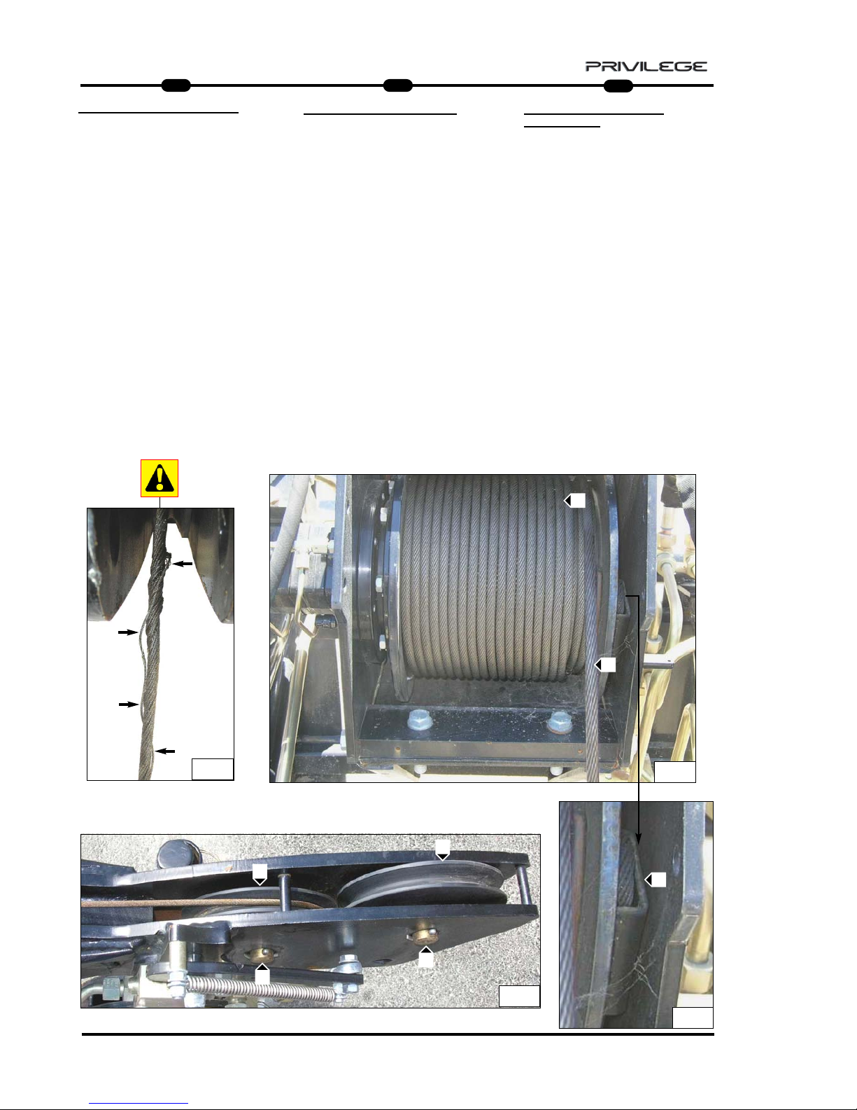
80
IT
EN
DE
5
MRT 1850 - 2150 - 2540
SEIL, RIEMENSCHEIBE und
SEILSCHLINGE
Täglich prüfen, dass das Seil A (Abb. 7)
immer einen sehr guten Zustand aufweist, dass keine Seilfasern gerissen sind
(Abb. 7a) und dass das Seil gut um die
Trommel B aufgewickelt ist (Abb. 7).
Andernfalls ist das Seil durch ein neues
mit dem gleichen Durchmesser und den
gleichen Eigenschaften zu ersetzen.
Die Schmierung des Seils prüfen. Muss
es geschmiert werden, dazu ein
Industriefett oder ein synthetisches
Staubschutzfett benutzen.
Die Bolzen C (Abb. 8), auf dem sich die
Führungsscheiben D (Abb. 8) drehen,
täglich prüfen und geschmiert halten.
Diese muss sich immer gut drehen.
Falls erforderlich, den Bolzen mit
Lithiumseifenfett schmieren.
Die Seilschlaufe E (Abb. 9) und die
Bügelklemmen auf Unversehrtheit
prüfen.
ROPE, PULLEY
and TERMINAL
Check rope A (Fig.7) daily to make sure
it is good condition, that there are no
broken filaments (Fig.7a) and that it is
wound properly around drum B (Fig.7).
If this is not the case, replace the rope
with a new one having the same diameter and features.
Check the lubrication of the rope, and if,
necessary, lubricate with industrial
grease or Dust-proof synthetic oil.
Check and lubricate pins C (Fig.8) on
which guide pulleys D (Fig.8) rotate,
and these must rotate freely.
If necessary, lubricate the pin with
lithium soap grease.
Check terminal E (Fig.9) and the rope-
holder clamps to make sure they are
intact.
FUNE, PULEGGIA
e CAPOCORDA
Controllare giornalmente che la fune
A (Fig.7) sia sempre in ottimo stato, che
non ci siano filamenti rotti (Fig.7a) e che
sia ben arrotolata sul tamburo B (Fig.7).
Altrimenti sostituirla con una nuova e
dello stesso diametro e caratteristiche.
Controllare la lubrificazione della fune,
se necessita lubrificare con grasso
industriale oppure olio sintetico antipolvere.
Controllare e mantenere lubrificato i
perni C (Fig.8) su cui ruotano le puleggie di guida D (Fig.8), che
dovranno avere sempre un buono
movimento di rotazione.
Se necessita, lubrificare con grasso al
sapone di litio il perno.
Assicurarsi dell’integrità dei capocorda
E (Fig.9) e dei suoi morsetti fermafune.
9
7
7a
A
B
E
E
8
9
E
C
D
C
D
Page 83

81
IT
EN
DE
5
MRT 1850 - 2150 - 2540
SHACLE AND CLAMPS
It is important to check the condition and
locking of the clamp screws F (Fig.10)
and the shackle G bolt (Fig.10) once a
week.
HOOK
For maximum efficiency, keep the hook
rotation screw N lubricated (Fig.10).
Without load suspended, the hook must
rotate freely, merely by pressing with the
hand P (Fig.10).
Check the condition and working of
safety tab O (Fig.10).
SCHÄKEL
UND KLEMMEN
Es ist wichtig, immer die Schrauben der
Klemmen F (Abb. 10) und des
Schraubbolzens des Schäkels G (Abb.
10) einmal pro Woche auf
Unversehrtheit und festen Sitz zu prüfen.
KRANHAKEN
Für eine maximale Effizienz und
Sicherheit die Rotationsschraube des
Kranhakens N geschmiert halten
(Abb. 10).
Ohne hängende Last muss der
Kranhaken sich immer frei und nur
durch Handdruck drehen P (Abb. 10).
Den Zustand und die Effizienz des
Sicherheitskeils prüfen O (Abb. 10).
GRILLO
e MORSETTI
È importante verificare l’integrità e il serraggio delle viti dei morsetti F (Fig.10) e del
bullone del grillo G (Fig.10) una volta alla
settimana.
GANCIO
Per una massima efficenza mantenere
lubrificata la vite di rotazione del gancio
N (Fig.10).
Senza carico sospeso, il gancio deve
sempre ruotare liberamente e con la sola
pressione della mano P (Fig.10).
Controllare lo stato e l’efficenza della
linguetta di sicurezza O (Fig.10).
10
O
N
F
F
P
G
Page 84

82
IT
EN
DE
5
MRT 1850 - 2150 - 2540
FINE CORSA DISCESA FUNE (Fig.11)
Giornalmente per una massima efficenza
mantenere sempre pulito il pistoncino e la
valvola idraulica di sicurezza; controllare il
serraggio dei raccordi e lo stato dei tubi .
Inoltre verificare l’integrità del leveraggio di
contatto finecorsa discesa e la tenuta della
sua molla.
FINE CORSA
SALITA FUNE
Giornalmente per una massima efficenza
mantenere sempre pulito il pistoncino e la
valvola idraulica di sicurezza; controllare il
serraggio dei raccordi e lo stato dei tubi .
Inoltre verificare l’integrità del leveraggio di
contatto finecorsa discesa e la tenuta della
sua molla. (Fig.12)
IMPIANT
O IDRAULICO (Fig.13)
Ispezionare giornalmente raccordi, valvole,
tubi, per evitare eventuali perdite di olio
che comprommettano il rendimento e la
durata dell’argano.
13
11
12
ROPE DESCENT LIMIT STOP (Fig.11)
Keep the piston and hydraulic safety
valve cleaned daily for maximum efficiency; check the unions and pipes to
make sure they are tightened properly.
Check the condition of the descent limit
stop contact leverage and the seal on its
spring.
ROPE LIFT LIMIT ST
OP
Keep the piston and hydraulic safety
valve cleaned daily for maximum efficiency; check the unions and pipes to
make sure they are tightened properly.
Also check the condition of the descent
limit stop contact leverage and the seal
on its spring. (Fig.12)
HYDRAULIC SYSTEM
(Fig.13)
Inspect the unions, valves, pipes daily to
prevent oil leakage which will affect the
working and life of the winch.
ENDSCHAL
TER SEIL
SENKEN
(Abb. 11)
Für die maximale Effizienz den Kolben und
das hydraulische Sicherheitsventil täglich reinigen. Den Anschluss der Verbindungen und
den Zustand der Leitungen prüfen.
Außerdem das Kontaktgestänge des
Endschalters für Seilsenken auf
Unversehrtheit und die Funktionstüchtigkeit
seiner Feder prüfen.
ENDSCHALTER SEIL HEBEN
Für die maximale Effizienz den Kolben und
das hydraulische Sicherheitsventil täglich reinigen. Den Anschluss der Verbindungen und
den Zustand der Leitungen prüfen.
Außerdem das Kontaktgestänge des
Endschalters für Seilheben auf Unversehrtheit
und die Funktionstüchtigkeit seiner Feder prüfen. (Abb. 12)
HYDRAULISCHE
ANLAGE (Abb. 13)
Anschlüsse, Ventile, Leitungen täglich prüfen,
um etwaige Leckstellen zu vermeiden, welche
die Leistung und die Haltbarkeit der Winde in
Frage stellen.
Page 85

83
IT
EN
DE
5
MRT 1850 - 2150 - 2540
0.80 mm
0.80 mm
250 bar
A1
M
F
N.A.
A
N
S
R
I.R. (1) I.R. (2)
C3
0.50 mm
C1 C2 D
C4
C5
V2C6V1
3mm
Winch 3T= 220 bar
Pt 1500 = 215 bar
Pt 2000 = 170 bar
Pt 800 = 150 bar
HHHHYYYYDDDDRRRRAAAAUUUULLLLIIIICCCC SSSSCCCCHHHHEEEEMMMMEE
EE
A = WINCH
N.A. = MAXIMUM DESCENT
MICROSWITCH
R = OIL TANK
I.R.1 = QUICK-RELEASE COUPLING
I.R.2 = QUICK-RELEASE COUPLING
A1 = MAXIMUM ASCENT
MICROSWITCH
S = VALVE
N = MAXIMUM PRESSURE VALVE
M = MOTOR
F = BRAKE
SSSSCCCCHHHHEEEEMMMMAAAA HHHHYYYYDDDDRRRRAAAAUUUULLLLIIIIKK
KK
A = STEHENDE WINDE
N.A. = MIKROSCHALTER MAXIMALE
SENKUNG
R = ÖLBEHÄLTER
I.R.1 = SCHNELLKUPPLUNG
I.R.2 = SCHNELLKUPPLUNG
A1 = MIKROSCHALTER MAXIMALE
HEBUNG
S = VENTIL
N = ÜBERDRUCKVENTIL
M = MOTOR
F = BREMSE
SSSSCCCCHHHHEEEEMMMMAAAA IIIIDDDDRRRRAAAAUUUULLLLIIIICCCCOO
OO
A = ARGANO
N.A. = MICRO MASSIMA
DISCESA
R = SERBATOIO OLIO
I.R.1 = INNESTO RAPIDO
I.R.2 = INNESTO RAPIDO
A1 = MICRO MASSIMA
SALITA
S = VALVOLA
N = VALVOLA MASSIMA
PRESSIONE
M = MOTORE
F = FRENO
Page 86

84
IT
EN
DE
5
MRT 1850 - 2150 - 2540
HOIST P 2000 P 2000 ANGRIFFSSCHENRELBRACCETTO P 2000
CARATTERISTICHE - CHARACTERISTICS - DATEN
DESCRIZIONE
DESIGNATION
BESCHREIBUNG
MIS. INGOMBRO
OVERAL
LENGTH
ABMESSUNGEN
(mm)
ACCESSORIO
ATTACHMENT
ZUBEHOER
D
PESO
WEIGHT
GEWITCH
P 2000
2000 Kg
900 mm 190 Kg
CAPACITA’
CAPACITY
KAPAZITAET
A B C
830 1060 2530
C
B
D
Q
A
DIS. GANCIO
HOOK
DISTANCE
2325 mm
Page 87

85
IT
EN
DE
5
MRT 1850 - 2150 - 2540
PT 2000 ANGRIFFSSCHENREL
: only for MRT 2540 and 2440 EPS
HOIST WITH WINCH PT 2000
: only for MRT 2540 and 2440 EPS
BRACCETTO PT 2000
: solo per MRT 2540 e 2440 EPS
C
B
D
A
PT 2000
2000 Kg
IDRAULICO
HYDRAULIC
HYDRAULIK
387 Kg830 868 2250
CARATTERISTICHE - CHARACTERISTICS - DATEN
DESCRIZIONE
DESIGNATION
BESCHREIBUNG
FUNE
ROPES
SEIL
VELOCITA’ GANCIO
TOW SPEED
HAKEN
GESCHWINDIGKEIT
FINE CORSA
UP/DOWN
ENDLAUF
MIS. INGOMBRO
OVERAL LENGTH
ABMESSUNGEN
mm
GANCIO “CE“
HOOK “CE”
HAKEN “CE”
PESO
WEIGHT
GEWITCH
Ø 10 mm
x 46 m
(x 52 m)
23 m/min
PRESSIONE DI
ESERCIZIO
OPERATING
PRESSURE
BETRIEBSDRUCK
A B C
5 T
Ø
AVVOLGIMENTO
PULEGGIA
Ø WINDING
PULLEY
WICKEL-Ø
RIEMENSCHEIBE
200 mm
Ø
AVVOLGIMENTO
TAMBURO
Ø WINDING
DRUM
WICKEL-Ø
TROMMEL
233 mm
170 Bar max
CAPACITA’
CAPACITY
KAPAZITAET
D
730
Page 88
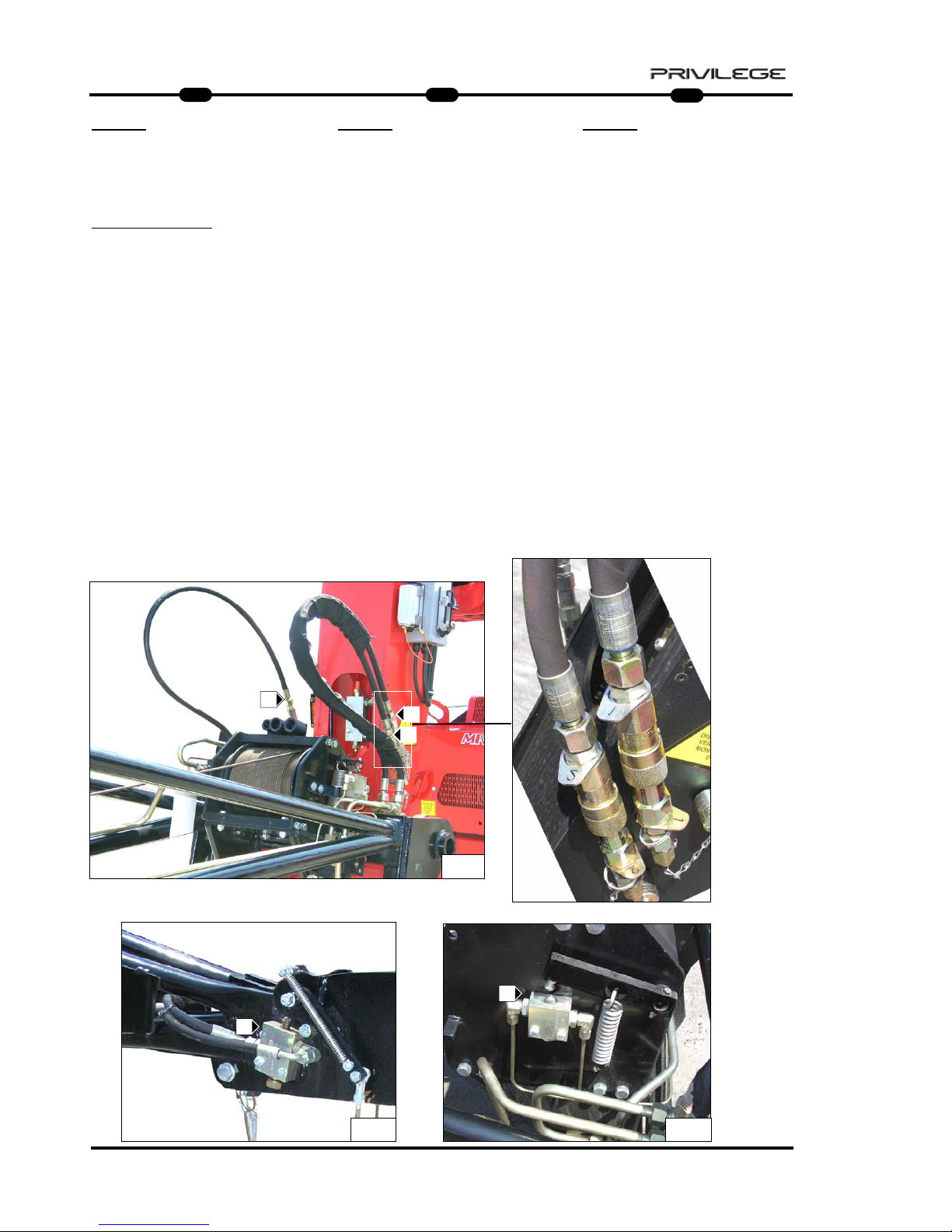
86
IT
EN
DE
5
MRT 1850 - 2150 - 2540
PT 2000
MMMMEEEESSSSSSSSAAAAIIIINNNN SSSSEEEERRRRVVVVIIIIZZZZIIIIOOOO EEEE UUUUTTTTIIIILLLLIIIIZZZZZZZZOO
OO
Per la vostra sicurezza, prima di iniziare
un ciclo di lavoro, attenersi alle
Istruzioni obbligatorie di verifica e
controllo:
- verificare l’integrità della struttura
esterna dell’argano e del braccetto
tralicciato.
- verificare il corretto collegamento
idraulico degli innesti rapidi 1, 2,
Drenaggio e lo stato dei tubi flessibili
(Fig.1);
- controllare il corretto funzionamento
del fine corsa discesa fune H (Fig.2);
- controllare il corretto funzionamento
del fine corsa salita fune L (Fig.2);
2
1
2
H
L
D
1
2
PT 2000
CCCCOOOOMMMMMMMMIIIISSSSSSSSIIIIOOOONNNNIIIINNNNGGGG AAAANNNNDDDD UUUUSSSSEE
EE
For your safety, before starting a work
cycle, follow the compulsory instruc-
tions for inspection and checking:
- check the outer frame of the winch and
the trestle arm.
- ensure correct hydraulic connection of
quick-release couplings 1, 2,
Drainage and the condition of the hose
pipes (Fig.1);
- check the correct working of the rope
descent limit stop H (Fig.2);
- check the correct working of the rope
lift limit stop L (Fig.2);
PT 2000
IIIINNNNBBBBEEEETTTTRRRRIIIIEEEEBBBBNNNNAAAAHHHHMMMMEEEE UUUUNNNN GGGGEEEEBBBBRRRRAAAAUUUUCCCCHH
HH
Bevor Sie einen Arbeitszyklus beginnen,
sollten Sie sich zu Ihrer Sicherheit an
die obligatorischen Prüfvorschriften
halten:
- Die Außenstruktur der Winde und des
Gittermastauslegers auf Unversehrtheit
prüfen.
- Den korrekten hydraulischen Anschluss
der Schnellkupplungen 1, 2, der
Rücklaufleitung und den Zustand der
Schläuche prüfen (Abb. 1).
- Den korrekten Betrieb des Endschalters
Seil senken H prüfen (Abb. 2).
- Den korrekten Betrieb des Endschalters
Seil heben L prüfen (Abb. 2).
Page 89
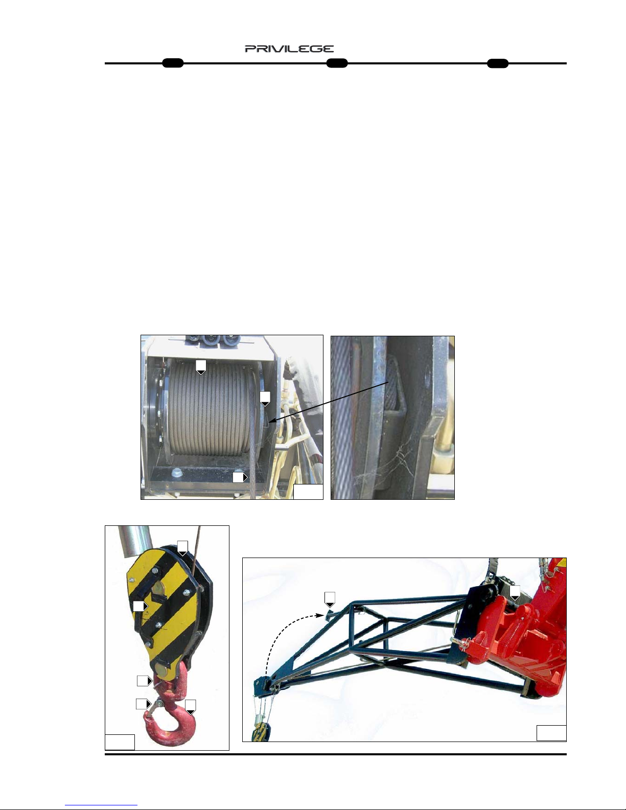
87
IT
EN
DE
5
MRT 1850 - 2150 - 2540
- controllare lo stato della fune B (Fig.3) e il
corretto avvolgimento sul tamburo
A (Fig.3);
- controllare il corretto movimento
rotazione delle puleggie di
guida fune F1 (Fig.4);
- controllare lo stato del capocorda
C (Fig.3);
- verificare l’integrità del bozzello F (Fig.4)
- verificare lo stato del gancio K (Fig.4):
che non sia deformato, che ruoti
liberamente e che la linguetta di
sicurezza sia efficente K1 (Fig.4);
- controllare l’aggancio del braccetto alla
macchina operatrice J (Fig.5).
Dalla posizione di parcheggio è possibile
sganciare il piede di appoggio e
posizionarlo all’interno del braccetto per
operare senza ulteriori ingombri J1 (Fig.5).
3
A
B
4
5
K1
J1
J
C
F
K
K
F1
- check the condition of the rope B (Fig.3)
and its winding around drum A (Fig.3);
- check the correct movement and
rotation of the rope guide pulleys
F1 (Fig.4);
- check the condition of terminal
C (Fig.3);
- check block F to make sure it is intact
(Fig.4)
- check to make sure the shackle
connecting the rope and hook is
screwed on properly K (Fig.4) and that
terminals K1 (Fig.4) block the rope.
- check the hook: make sure it is not
deformed, that it turns freely and that
the safety tab is efficient G (Fig.4);
- check the hooking of the arm to the
operating machine J (Fig.5).
From the parking position, it is possible
to unhook the supporting feet and position it inside the arm to work without
further impediment J1 (Fig.5).
- Den Zustand des Seils B prüfen (Abb. 3)
und die korrekte Aufwicklung um die
Trommel A prüfen (Abb. 3).
- Die korrekte Seiten- und
Rotationsbewegung der
Seillenkscheibe F1 prüfen (Abb. 4).
- Den Zustand der Kabelschlaufen
C (Abb. 3) prüfen.
- Die Umlenkrolle F auf Unversehrtheit
prüfen (Abb. 4)
- Sicherstellen, dass der
Seilverbindungsschäkel und der
Kranhaken gut eingeschraubt sind
K (Abb. 4) und dass die Klemmen
K1 (Abb. 4) das Seil blockieren.
- Den Zustand des Kranhakens prüfen:
Er darf nicht deformiert sein, muss sich
frei drehen können und der
Sicherheitskeil G muss effizient sein
(Abb. 4).
- Sicherstellen, dass die Winde an der
Arbeitsmaschine J eingerastet ist
(Abb. 5).
Aus der Abstellposition die Winde kann
man den Abstellfuß ausklinken und ihn
innerhalb des Auslegers anordnen, ohne
noch mehr Platz in Anspruch zu
nehmen. J1 (Abb. 5)
Page 90

88
IT
EN
DE
5
MRT 1850 - 2150 - 2540
MMMMAAAANNNNUUUUTTTTEEEENNNNZZZZIIIIOOOONNNNEEEE
- RIDUTTORE
- FUNE, PULEGGIA
e CAPOCORDA
- BOZZELLO
- GANCIO
- FINE CORSA DISCESA FUNE
- FINE CORSA SALITA FUNE
- IMPIANTO IDRAULICO
MMMMAAAAIIIINNNNTTTTEEEENNNNAAAANNNNCCCCEEEE
- GEAR REDUCER
- ROPE, PULLEY AND TERMINAL
- BLOCK
- HOOK
- ROPE DESCENT LIMIT ST
OP
- ROPE LIFT LIMIT STOP
- HYDRAULIC SYSTEM
WWWWAAAARRRRTTTTUUUUNNNNGG
GG
- GETRIEBE
- SEIL, RIEMENSCHEIBE UND
SEILSCHLAUFE
- UMLENKROLLE
- KRANHAKEN
- ENDSCHAL
TER SEIL SENKEN
- ENDSCHAL
TER SEIL HEBEN
- HYDRAULISCHE ANLAGE
Page 91

89
IT
EN
DE
5
MRT 1850 - 2150 - 2540
RIDUTT
ORE
Una corretta lubrificazione consente un
buon funzionamento e una lunga durata
del riduttore.
Per accedere all’indicatore di livello o al
tappo di rabbocco olio, occorre srotolare
completamente la fune dal tamburo.
Controllare il livello dell’olio almeno una
volta al mese B (Fig.6) e all’occorrenza
rabboccare A (Fig.6) con olio dello stesso
tipo di quello presente all’interno del
riduttore ( ISO VG 150) .
Si consiglia l’utilizzo di olio per ingranaggi
con addittivazione EP con viscosità ISO
VG, dipendente dalla temperatura di
esercizio.
La prima sostituzione dell’ olio deve
esser effettuata dopo 100 ore di funzionamento, successivamente ogni 12 mesi o
ogni 2000 ore di funzionamento.
-Eseguire il cambio dell’olio con riduttore
ancora caldo per facilitare un completo
svuotamento.
- Per scaricare l’olio, ruotare il tamburo del
motore portando il tappo di rabbocco /
scarico A (Fig.6a) verso il basso.
- Svitare il tappo A (Fig.6a) e scaricare
completamente l’olio.
- Ruotare il tamburo portando il foro di
rabbocco/scarico verso l’alto A (Fig.6).
- Svitare il tappo di livello olio B (Fig.6);
- Rabbocare con olio nuovo e di tipo
corretto fino a quando l’olio non fuoriesce
da foro di livelo B (Fig.6). (0,25 lt)
- Riavvitare i tappi e riavvolgere la fune.
A
A
B
6a6
B
A
GEAR REDUCER
Correct lubrication will allow efficient
working and long life of the gear
reducer.
The rope must be unwound completely
from the drum to access the level indicator or oil filler plug.
Check the oil level at least once a
month B (Fig.6) and top up if necessary
A (Fig.6) with the same type of oil as
that present in the gear reducer
( ISO VG 150) .
Use of gear oil with EP additives, with
viscosity ISO VG, depending on the
operating temperature, is recommended.
Oil must be changed the first time
after 100 hours of operation, and subsequently every 12 months or every 2000
hours of operation.
- Change the oil with the gear reducer
still hot so that the oil drains out
completely.
- To drain out the oil, turn the motor
drum so that the filler/drain plug
A (Fig.6a) is downwards.
- Unscrew plug A (Fig.6a) and drain out
the oil completely.
- Turn the drum so that the filler/drain
plug is upwards A (Fig.8).
- Unscrew the oil level plug B (Fig.6);
- Fill with the right type of oil until it
starts flowing out through the level hole
B (Fig.6).(0,25 lt)
- Refit the plugs and rewind the rope.
GETRIEBE
Die korrekte Schmierung gewährleistet
den guten Betrieb und die lange
Haltbarkeit des Getriebes.
Um Zugriff zum Ölstand- und Öleinfüllstopfen zu erhalten, ist das Seil ganz
von der Trommel abzuwickeln.
Den Ölstand mindestens einmal im
Monat prüfen B (Abb. 6) und bei Bedarf
Öl nachfüllen A (Abb. 6). Dazu Öl der
gleichen Sorte wie das verwenden, das
im Getriebe schon vorhanden ist
( ISO VG 150).
Am besten benutzt man Öl für Getriebe
mit EP-Zusatz mit Viskosität ISO VG je
nach der Betriebstemperatur.
Der erste Ölwechsel ist nach 100
Betriebsstunden fällig, dann jeweils alle
12 Monate bzw. alle 2000
Betriebsstunden.
- Die Ölwechsel bei noch warmen
Getriebe ausführen, um des ganz
auslaufen zu können.
- Um das Öl abzulassen, die Trommel
des Motors drehen, um den Nachfüll/Ablaufstopfen A (Abb.6a) nach unten
zu bringen.
- Den Stopfen A (Abb. 6a) losschrauben
und das Öl ganz auslaufen lassen.
- Die Trommel drehen, indem man den
Nachfüll-/Ablaufstopofen A nach oben
bringt (Abb. 6).
- Den Ölstandstopfen B abschrauben
(Abb. 6).
- Das neue Öl des korrekten Typs
nachfüllen, bis das Öl aus der
Standschraube B ausläuft
(Abb. 6).(0,25 lt)
- Die Stopfen wieder aufschrauben und
das Seil aufwickeln.
Page 92

90
IT
EN
DE
5
MRT 1850 - 2150 - 2540
FUNE, PULEGGIA
e CAPOCORDA
Controllare giornalmente che la fune
A (Fig.7) sia sempre in ottimo stato, che
non ci siano filamenti rotti (Fig.7a) e che
sia ben arrotolata sul tamburo B (Fig.7).
Altrimenti sostituirla con una nuova e
dello stesso diametro e caratteristiche.
Controllare la lubrificazione della fune,
se necessita lubrificare con grasso
industriale oppure olio sintetico antipolvere.
Controllare e mantenere lubrificato i
perni C (Fig.8) su cui ruotano le
puleggie di guida D (Fig.8), che
dovranno avere sempre un buono
movimento di rotazione.
Se necessita, lubrificare con grasso al
sapone di litio il perno.
Assicurarsi dell’integrità dei capocorda
E (Fig.9) e dei suoi morsetti fermafune.
9
7
7a
A
B
E
E
8
9
E
C
D
C
D
SEIL, RIEMENSCHEIBE und
SEILSCHLINGE
Täglich prüfen, dass das Seil A (Abb. 7)
immer einen sehr guten Zustand aufweist, dass keine Seilfasern gerissen sind
(Abb. 7a) und dass das Seil gut um die
Trommel B aufgewickelt ist (Abb. 7).
Andernfalls ist das Seil durch ein neues
mit dem gleichen Durchmesser und den
gleichen Eigenschaften zu ersetzen.
Die Schmierung des Seils prüfen. Muss
es geschmiert werden, dazu ein
Industriefett oder ein synthetisches
Staubschutzfett benutzen.
Die Bolzen C (Abb. 8), auf dem sich die
Führungsscheiben D (Abb. 8) drehen,
täglich prüfen und geschmiert halten.
Diese muss sich immer gut drehen.
Falls erforderlich, den Bolzen mit
Lithiumseifenfett schmieren.
Die Seilschlaufe E (Abb. 9) und die
Bügelklemmen auf Unversehrtheit
prüfen.
ROPE, PULLEY
and TERMINAL
Check rope A (Fig.7) daily to make sure
it is good condition, that there are no
broken filaments (Fig.7a) and that it is
wound properly around drum B (Fig.7).
If this is not the case, replace the rope
with a new one having the same diameter and features.
Check the lubrication of the rope, and if,
necessary, lubricate with industrial
grease or Dust-proof synthetic oil.
Check and lubricate pins C (Fig.8) on
which guide pulleys D (Fig.8) rotate,
and these must rotate freely.
If necessary, lubricate the pin with
lithium soap grease.
Check terminal E (Fig.9) and the rope-
holder clamps to make sure they are
intact.
Page 93

91
IT
EN
DE
5
MRT 1850 - 2150 - 2540
BLOCK
For maximum efficiency and safety,
make sure the outer frame F (Fig.10) is
intact and check pulley G (Fig.1) to
make sure it rotates properly around its
pin G1 (Fig.10) .
Lubricate pin M with lithium soap grease, if necessary (Fig.10).
HOOK
For maximum efficiency, keep the hook
rotation screw N lubricated (Fig.10).
Without load suspended, the hook must
rotate freely, merely by pressing with the
hand P (Fig.10).
Check the condition and working of
safety tab O (Fig.10).
UMLENKROLLE
Für eine maximale Effizienz und
Sicherheit die Außenstruktur F (Abb. 10)
unversehrt halten und sicherstellen,
dass die Riemenscheibe G (Abb. 10)
sich korrekt um ihren Bolzen G1 dreht
(Abb. 10).
Falls erforderlich, den Bolzen M mit
Lithiumseifenfett schmieren (Abb. 10).
KRANHAKEN
Für eine maximale Effizienz und
Sicherheit die Rotationsschraube des
Kranhakens N geschmiert halten
(Abb. 10).
Ohne hängende Last muss der
Kranhaken sich immer frei und nur
durch Handdruck drehen P (Abb. 10).
Den Zustand und die Effizienz des
Sicherheitskeils prüfen O (Abb. 10).
BOZZELLO
Per una massima efficenza e sicurezza,
mantenere intatta la struttura esterna
F (Fig.10) e controllare che la puleggia
G (Fig.10) ruoti correttamente sul suo perno
G1 (Fig.10) .
Se necessità, lubrificare con grasso al
sapone di litio il perno G1 (Fig.10).
GANCIO
Per una massima efficenza mantenere
lubrificata la vite di rotazione del gancio
N (Fig.10).
Senza carico sospeso, il gancio deve
sempre ruotare liberamente e con la sola
pressione della mano P (Fig.10).
Controllare lo stato e l’efficenza della
linguetta di sicurezza O (Fig.10).
G
10
O
N
G1
F
F
P
Page 94

92
IT
EN
DE
5
MRT 1850 - 2150 - 2540
FINE CORSA DISCESA FUNE (Fig.11)
Giornalmente per una massima efficenza
mantenere sempre pulito il pistoncino e la
valvola idraulica di sicurezza; controllare il
serraggio dei raccordi e lo stato dei tubi.
Inoltre verificare l’integrità del leveraggio di
contatto finecorsa discesa e la tenuta della
sua molla.
FINE CORSA
SALITA
FUNE
Giornalmente per una massima efficenza
mantenere sempre pulito il pistoncino e la
valvola idraulica di sicurezza; controllare il
serraggio dei raccordi e lo stato dei tubi .
Inoltre verificare l’integrità del leveraggio di
contatto finecorsa discesa e la tenuta della
sua molla. (Fig.12)
IMPIANT
O
IDRAULICO
(Fig.13)
Ispezionare giornalmente raccordi, valvole,
tubi, per evitare eventuali perdite di olio
che comprommettano il rendimento e la
durata dell’argano.
12
13
11
ROPE DESCENT LIMIT STOP (Fig.11)
Keep the piston and hydraulic safety
valve cleaned daily for maximum efficiency; check the unions and pipes to
make sure they are tightened properly.
Check the condition of the descent limit
stop contact leverage and the seal on its
spring.
ROPE LIFT LIMIT ST
OP
Keep the piston and hydraulic safety
valve cleaned daily for maximum efficiency; check the unions and pipes to
make sure they are tightened properly.
Also check the condition of the descent
limit stop contact leverage and the seal
on its spring. (Fig.12)
HYDRAULIC SYSTEM
(Fig.13)
Inspect the unions, valves, pipes daily to
prevent oil leakage which will affect the
working and life of the winch.
ENDSCHAL
TER SEIL SENKEN (Abb. 11)
Für die maximale Effizienz den Kolben und
das hydraulische Sicherheitsventil täglich reinigen. Den Anschluss der Verbindungen und
den Zustand der Leitungen prüfen.
Außerdem das Kontaktgestänge des
Endschalters für Seilsenken auf
Unversehrtheit und die Funktionstüchtigkeit
seiner Feder prüfen.
ENDSCHAL
TER SEIL HEBEN
Für die maximale Effizienz den Kolben und
das hydraulische Sicherheitsventil täglich reinigen. Den Anschluss der Verbindungen und
den Zustand der Leitungen prüfen.
Außerdem das Kontaktgestänge des
Endschalters für Seilheben auf Unversehrtheit
und die Funktionstüchtigkeit seiner Feder prüfen. (Abb. 12)
HYDRAULISCHE ANLAGE (Abb. 13)
Anschlüsse, Ventile, Leitungen täglich prüfen,
um etwaige Leckstellen zu vermeiden, welche
die Leistung und die Haltbarkeit der Winde in
Frage stellen.
Page 95

93
IT
EN
DE
5
MRT 1850 - 2150 - 2540
0.80 mm
0.80 mm
250 bar
A1
M
F
N.A.
A
N
S
R
I.R. (1) I.R. (2)
C3
0.50 mm
C1 C2 D
C4
C5
V2C6V1
3mm
Winch 3T= 220 bar
Pt 1500 = 215 bar
Pt 2000 = 170 bar
Pt 800 = 150 bar
HHHHYYYYDDDDRRRRAAAAUUUULLLLIIIICCCC SSSSCCCCHHHHEEEEMMMMEE
EE
A = WINCH
N.A. = MAXIMUM DESCENT
MICROSWITCH
R = OIL TANK
I.R.1 = QUICK-RELEASE COUPLING
I.R.2 = QUICK-RELEASE COUPLING
A1 = MAXIMUM ASCENT
MICROSWITCH
S = VALVE
N = MAXIMUM PRESSURE VALVE
M = MOTOR
F = BRAKE
SSSSCCCCHHHHEEEEMMMMAAAA HHHHYYYYDDDDRRRRAAAAUUUULLLLIIIIKK
KK
A = STEHENDE WINDE
N.A. = MIKROSCHALTER MAXIMALE
SENKUNG
R = ÖLBEHÄLTER
I.R.1 = SCHNELLKUPPLUNG
I.R.2 = SCHNELLKUPPLUNG
A1 = MIKROSCHALTER MAXIMALE
HEBUNG
S = VENTIL
N = ÜBERDRUCKVENTIL
M = MOTOR
F = BREMSE
SSSSCCCCHHHHEEEEMMMMAAAA IIIIDDDDRRRRAAAAUUUULLLLIIIICCCCOO
OO
A = ARGANO
N.A. = MICRO MASSIMA
DISCESA
R = SERBATOIO OLIO
I.R.1 = INNESTO RAPIDO
I.R.2 = INNESTO RAPIDO
A1 = MICRO MASSIMA
SALITA
S = VALVOLA
N = VALVOLA MASSIMA
PRESSIONE
M = MOTORE
F = FRENO
Page 96
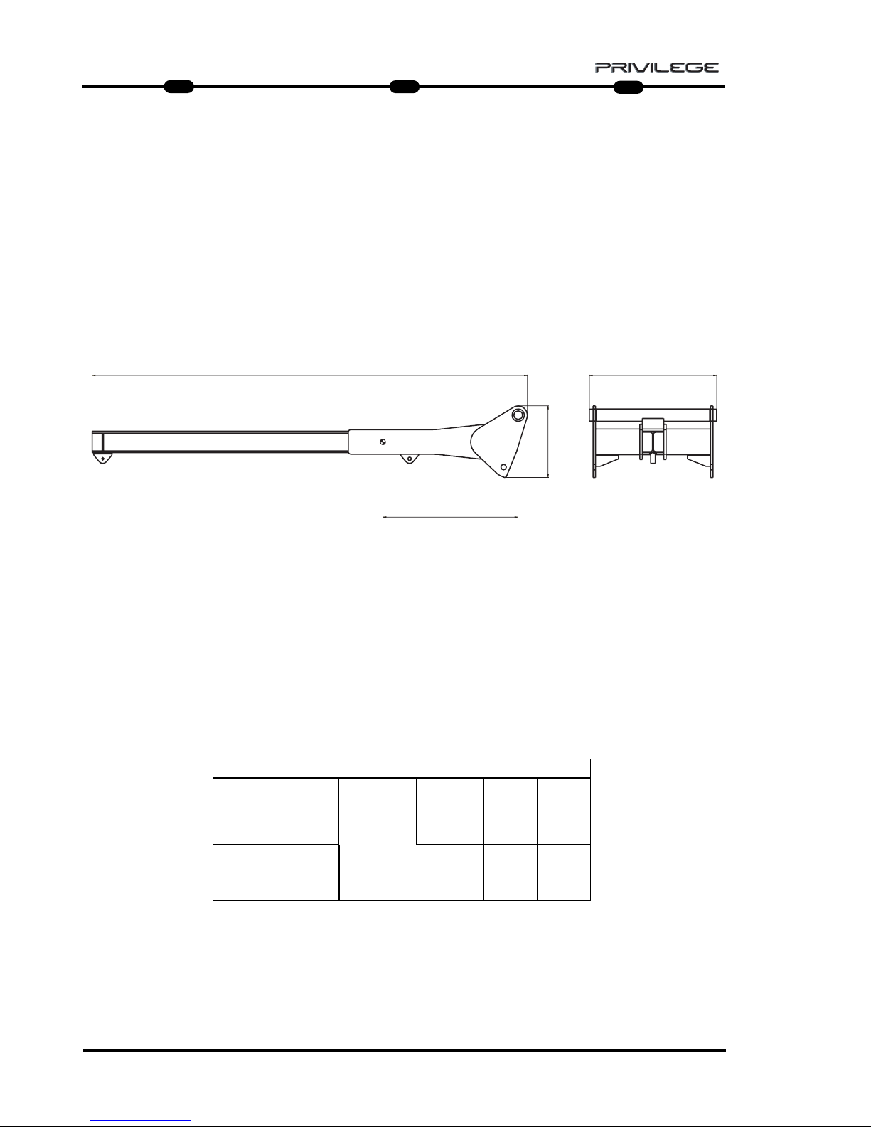
94
IT
EN
DE
5
MRT 1850 - 2150 - 2540
HOIST P 4000 P 4000 ANGRIFFSSCHENRELBRACCETTO P 4000
D
B
C
A
1200 KG
1200 KG
4000 KG
4000 KG
CARATTERISTICHE - CHARACTERISTICS - DATEN
DESCRIZIONE
DESIGNATION
BESCHREIBUNG
MIS. INGOMBRO
OVERAL
LENGTH
ABMESSUNGEN
(mm)
ACCESSORIO
ATTACHMENT
ZUBEHOER
D
PESO
WEIGHT
GEWITCH
P 4000
4000 Kg
880 mm 210 Kg
CAPACITA’
CAPACITY
KAPAZITAET
A B C
830 467 2838
Page 97

95
IT
EN
DE
5
MRT 1850 - 2150 - 2540
HOIST P 6000 P 6000 ANGRIFFSSCHENRELBRACCETTO P 6000
D
B
C
A
2000 KG
2000 KG
6000 KG
6000 KG
CARATTERISTICHE - CHARACTERISTICS - DATEN
DESCRIZIONE
DESIGNATION
BESCHREIBUNG
MIS. INGOMBRO
OVERAL LENGTH
ABMESSUNGEN
(mm)
ACCESSORIO
ATTACHMENT
ZUBEHOER
D
PESO
WEIGHT
GEWITCH
P 6000
6000 Kg
880 mm 210 Kg
CAPACITA’
CAPACITY
KAPAZITAET
A B C
830 467 2838
Page 98

Page 99

97
IT
EN
DE
5
MRT 1850 - 2150 - 2540
D
B
B
C'
C
D'
A
800 KG
1000 KG
PT 800 HOIST CRANE JIB CRANE JIB ANGRIFFSSCHENREL
PT800
BRACCETTO CRANE JIB PT 800
CRANE JIB PT 800
Kg 1000
IDRAULICO
HYDRAULIC
HYDRAULIK
606 Kg835 805
7310
CARATTERISTICHE - CHARACTERISTICS - DATEN
DESCRIZIONE
DESIGNATION
BESCHREIBUNG
FUNE
ROPES
SEIL
VELOCITA’ GANCIO
TOW SPEED
HAKEN
GESCHWINDIGKEIT
FINE CORSA
UP/DOWN
ENDLAUF
MIS. INGOMBRO
OVERAL LENGTH
ABMESSUNGEN
mm
GANCIO “CE“
HOOK “CE”
HAKEN “CE”
PESO
WEIGHT
GEWITCH
Ø 10 mm
x 46 m
45 m/min
PRESSIONE DI
ESERCIZIO
OPERATING
PRESSURE
BETRIEBSDRUCK
A B C
5 T
Ø AVVOLGIMENTO
PULEGGIA
230 mm
Ø AVVOLGIMENTO
TAMBURO
233 mm
150 Bar max
CAPACITA’
CAPACITY
KAPAZITAET
D
2480
4550
C’
D’
1705
Page 100

98
IT
EN
DE
5
MRT 1850 - 2150 - 2540
PT 800
CCCCOOOOMMMMMMMMIIIISSSSSSSSIIIIOOOONNNNIIIINNNNGGGG AAAANNNNDDDD UUUUSSSSEE
EE
For your safety, before starting a work
cycle, follow the compulsory instruc-
tions for inspection and checking:
- check the outer frame of the winch and
the trestle arm.
- ensure correct hydraulic connection of
quick-release couplings 1, 2,
Drainage and the condition of the hose
pipes (Fig.1);
- check the correct working of the rope
descent limit stop H (Fig.2);
- check the correct working of the rope
lift limit stop L (Fig.2);
PT 800
MMMMEEEESSSSSSSSAAAAIIIINNNN SSSSEEEERRRRVVVVIIIIZZZZIIIIOOOO EEEE UUUUTTTTIIIILLLLIIIIZZZZZZ
ZZOOOO
Per la vostra sicurezza, prima di iniziare
un ciclo di lavoro, attenersi alle
Istruzioni obbligatorie
di verifica e
controllo:
- verificare l’integrità della struttura
esterna dell’argano e del braccetto
tralicciato.
- verificare il corretto collegamento
idraulico degli innesti rapidi 1, 2,
Drenaggio e lo stato dei tubi flessibili
(Fig.1);
- controllare il corretto funzionamento
del fine corsa discesa fune H (Fig.2);
- controllare il corretto funzionamento
del fine corsa salita fune L (Fig.2);
1
2
L
D
1
2
2
H
PT 800
IIIINNNNBBBBEEEETTTTRRRRIIIIEEEEBBBBNNNNAAAAHHHHMMMMEEEE UUUUNNNN GGGGEEEEBBBBRRRRAAAAUUUUCCCCHH
HH
Bevor Sie einen Arbeitszyklus beginnen,
sollten Sie sich zu Ihrer Sicherheit an
die obligatorischen Prüfvorschriften
halten:
- Die Außenstruktur der Winde und des
Gittermastauslegers auf Unversehrtheit
prüfen.
- Den korrekten hydraulischen Anschluss
der Schnellkupplungen 1, 2, der
Rücklaufleitung und den Zustand der
Schläuche prüfen (Abb. 1).
- Den korrekten Betrieb des Endschalters
Seil senken H prüfen (Abb. 2).
- Den korrekten Betrieb des Endschalters
Seil heben L prüfen (Abb. 2).
F1
 Loading...