

Page 1
Operators manual
MANIP’ MPower
Réf. 25001403 - Février 2010
English
Page 2

SOMMAIRE
1• User information 1
2• Safety instructions 2
Obligations
otections
Pr
Warnings
3• Prohibitions 3
4• Safety stickers 4
5• Location of the stickers 5
6• Identification plate 5
7• Counter load 6
8• Use of the mono lever 6
9• Switching from double to single effect 7
rd
10• 3
11• User instructions 8-9
12• MM and HD loader detachment 10-11
13• MM and HD loader attachment 12-13
14• Hydraulic coupling Manip’Fast 14-15
15• Manip’Lock implement detachment 16
16
17• Hydraulic coupling Man
18• Lev
19• Manip’Pic 20
20• Manip’activ suspension
21• Collectivity kit
22• Maintenance 22-23
23• Trouble shooting 24
24• Technical characteristics 25
25• Warranty 26
26• Certificat of conformity 27
27• Notes 28-29
and 4thfunction 7
Obligations
arnings
W
Prohibitions
Advice
Connec
D
isconnect
• Manip’Lock implement attachment 17
el indicator 19
Safe
Tractor maintenance
Loader maintenance
Subframe maintenance
t
ip’Fast Outil 2 and 4 18
21
safety with lifting and tipping 2
ty
1
Page 3

Operators manual
USER INFORMATION
1•
GENERAL INFORMATION
To the user
You have just bought a Manip loader and we thank you for this.
Spare a moment to read this manual as it has been made to help
you use your loader at its maximum capacity.
When your loader was delivered, your dealer should have given
you a copy of your warranty certificate. If not ask him for a copy.
You will need this document if you have to make a warranty
claim. This claim will not be granted if a signed copy has not been
sent to us.
The warranty certificate indicates:
That the assembly is conforming to specifications and accepted.
That the user has received the manual.
That the user has been informed about the use of the loader,
about the attachment and detachment, about maintenance and
safety regulations.
That the warranty conditions have been read and accepted.
MANIP’ MPower
The user manual
is an important
document that should
be readily available
when needed.
IMPORTANT
A loader
is a complex tool;
incorrect or neglected
use may lead to
important damages.
Comply with the
safety regulations
1
Page 4

SAFETY REGULATIONS
2•
These regulations
should be
read carefully.
Non-compliance
with these will relieve
the Manip Company
from any responsibility
in event of any incidents
and may entail
the cancellation
of the warranty.
PROTECTION
against falling object and
tipping over.
OBLIGATIONS
Read the manual: Read and study carefully this manual before
using the loader, always have this manual within reach, store it
inside your tractor, if your manual is damaged or lost get another one.
Assembly out with the current recommendations at the date of
purchase is a risk for both the loader and the tractor. Consequently no warranty claim will be taken into consideration for
any assembly out with our recommendations.
On delivery the following should be explained:
Safety regulations.
Control workings and use.
Recommandations of use.
Attachment and detachment of the loader.
Attachment and detachment of the tools.
Some warning stickers are at different places on the loader and
on the tool, read them and understand their meanings before
using the loader or the tool.
If you cannot read one of the stickers or it has been damaged
then replace it.
Warning. If a tractor is not
equipped with a protection
against falling objects or a 4pole structure against tipping
over (tractors with 2-pole arch),
then the driver is exposed to
a continuous risk when he
manipulates a load.
Restrictions. In this case the
loader should be equipped
with a mechanism that maintains the tool level.
Reminder. Only tools recommended by Manip should be
used.
WARNING
A safety belt needs to be fitted and readjusted during work.
Use a sufficient counter-weight to ensure the stability of the
tractor. Around 20% of the total weight should be supported by
the rear axle.
Control the loader exclusively from the driver’s seat.
Keep control over the controls until movements are completed.
Transport on the road should be with the arm raised and empty.
Do not hide the traffic lights.
At your work place loaded implements should be transported in
a lowered position at all times and at a low speed, in particular
on uneven ground. Avoid working on slopes.
During work keep away any person in the area of the loader.
Be careful at all times that the loader does not interfere with
overhead obstacles.
Implement changing: check that they are properly locked on by
forcing down slightly on the ground.
When not being used, the detached loader should rest on its
parking stand with the pins and locking pins delivered with the
machine.
Only use implements suitable for the job to be done.
Periodically check the hydraulic system.
2
Page 5

Operators manual
PROHIBITIONS
3•
Standing under a loader is forbidden.
Never stay under a lifted loader unless the mechanical or hy-
draulic shut off device is in a locked position.
Never detach a loader without a tool. Always detach the loader
on a firm flat ground.
Never modify the original hose connection.
Never modify a sub frame. The sub frames are made for a spe-
cific type of tractor. Never fit a sub frame on a tractor that it is
not made for.
Any modification of the Manip equipment and the fitting of an
implement of another origin than Manip automatically cancels
the liability and the warranty on the entire equipment.
MANIP’ MPower
NEVER USE
THE LOADER FOR
ANYTHING OTHER
THAN TRANSPORT
OF MATERIALS
TO USE THE LOADER
FOR LIFTING WORK,
IT HAS TO BE EQUIPPED
WITH SAFETY VALVES
see page.23:
COLLECTIVITY KIT
safety with tipping
and lifting.
Norm EN 12525:
2000/prA1: July 2008
Manip may not be held liable in the event
of non-compliance with these safety regulations.
LIFTING
OR CARRYING
PEOPLE WITH
THE LOADER
IS FORBIDDEN.
3
Page 6
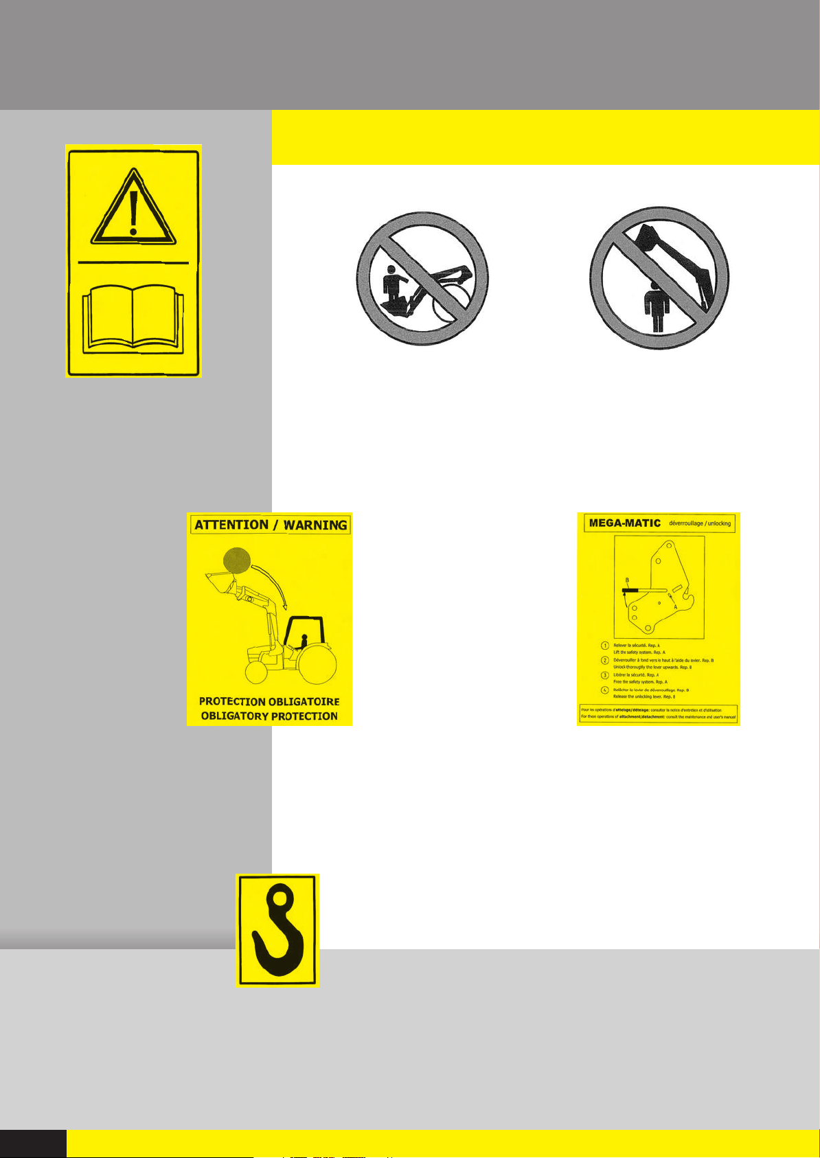
SAFETY STICKERS
4•
Read and keep
the maintenance
and user manual.
Never use the loader
To carry people
Compulsory
protections
against tipping
over and falling
objects
Do not stand under the
loader
Unlocking
Security device
Lifting hooks for
Loader maintenance
4
Page 7
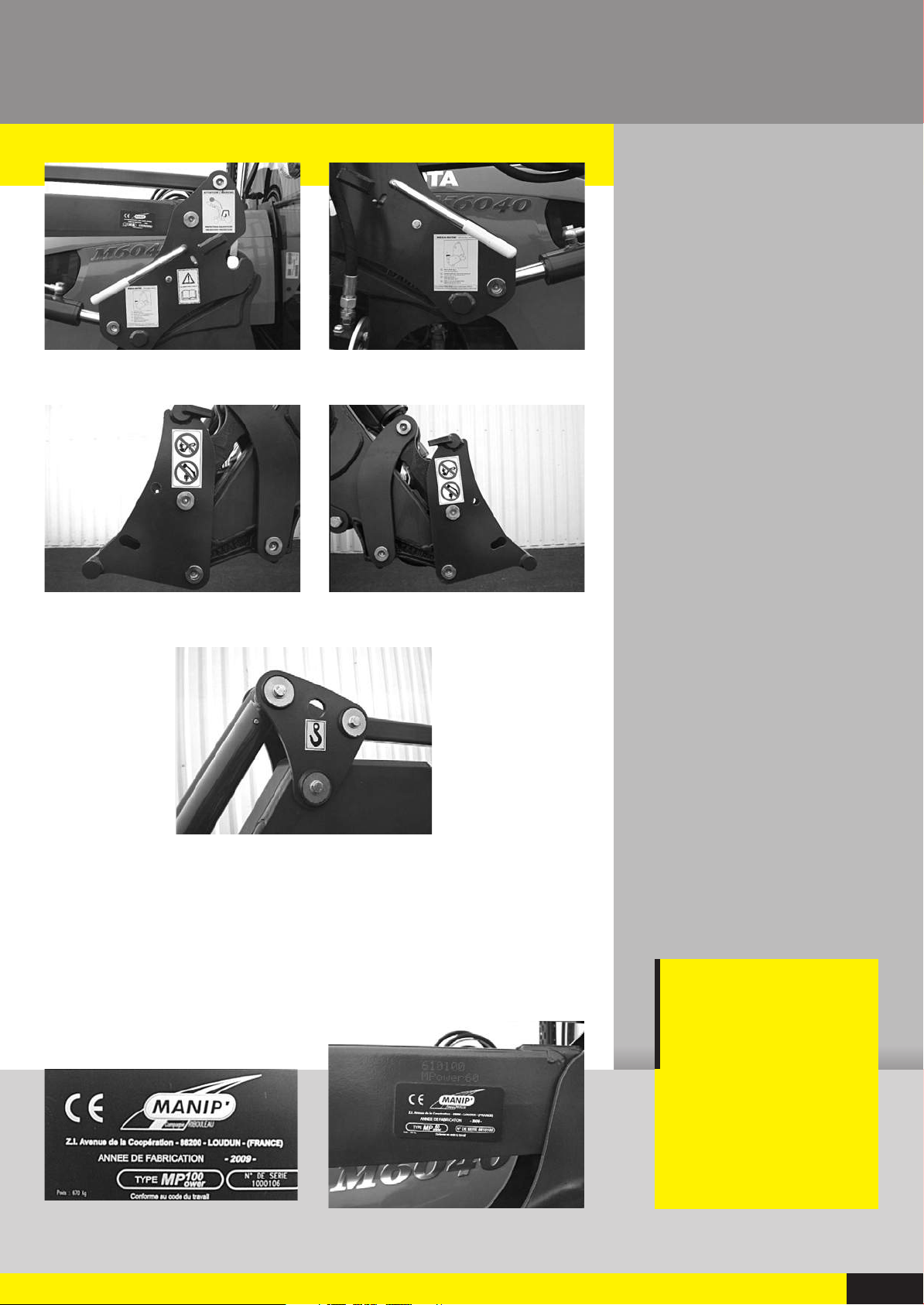
LOCATION
5•
Operators manual
OF THE STICKERS
Left bearing box
MANIP’ MPower
Right bearing box
Tool carrier left hand side
IDENTIFICATION PLATE
6•
The identification plate is located on the outside of the rear left
arm, is mentioned: Year of manufacture, Type or model; Serial
number; Weight.
Tool carrier right hand side
Tipping
balancing system
left and right
IMPORTANT
The loader serial
number is necessary
for any inquiry
about spare parts
or technical
assistance.
Location on the arm
5
Page 8
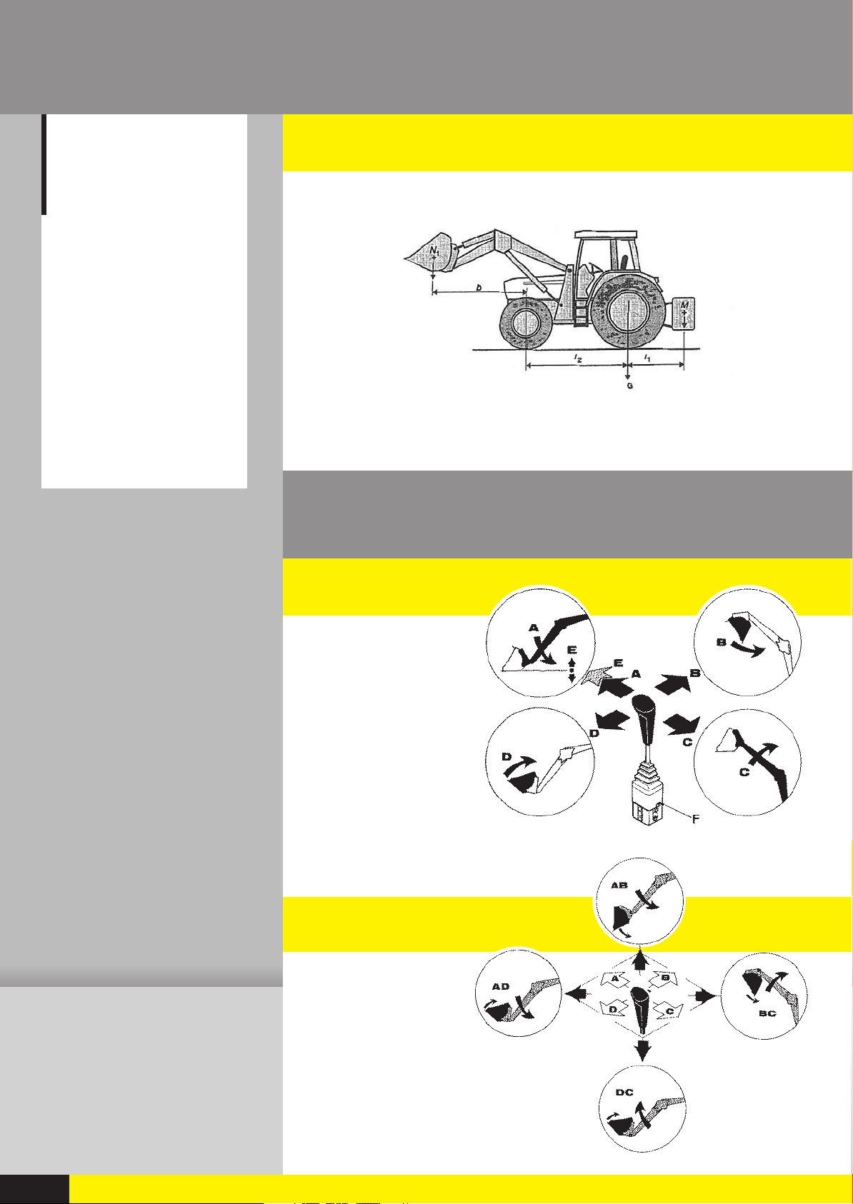
COUNTER LOAD
7•
Usage without
counterweight
When the use
of a counterweight
is not possible,
then the stability
can be maintained
by adding weights
on the rear wheel
or liquid in the tires
in accordance
to the following
formula:
- N x b P + N
G x I
2
------------------------------------- --------------I
2
5
METHOD OF CALCULATION
12525:2000
Fig B.1 – Static stability calculation
USE OF THE MONO LEVER
8•
SINGLE FUNCTIONS
A Down
B Tip
C Lift
D Dig
E Float
COMBINED FUNCTIONS
A-B Down, Tip
A-D Down, Dig
B-C Lift, Tip
D-C Lift, Dig
6
Page 9

9•
SWITCHING FROM DOUBLE
Operators manual
TO SINGLE EFFECT LIFTING
Loader with Manip monolever
and Manip Drive only
A valve situated underneath the
distributor allows you to switch from
SINGLE EFFECT (VALVE OPEN)
DOUBLE EFFECT (VALVE CLOSED)
MANIP’ MPower
RD
10•
3rdFUNCTION
Double effect hydraulic function to command a tool’s hydraulics
This 3rd function is activated by a switch situated on the side of
the mono lever.
When the switch is activated, then the mono lever in a tip or
dig position will order the opening or closing of a tool.
When the switch is released then the mono lever will command
the tipping or digging of the tool.
th
4
Supplementary double effect hydraulic function to command a
double function tool’s hydraulics.
This 4th function is activated by a switch situated on the side of
the mono lever.
When the switch is activated, then the mono lever in a tip or dig
position will command the 2nd tool’s cylinder (lift, accessories…)
When the switch is released, then the monolever will command
the tipping or digging of the tool.
3
FUNCTION
AND 4
TH
FUNCTION
3rdfunction command
4thfunction command
7
Page 10

11•
USER INSTRUCTIONS
MANIP tools
have been designed
for specific use,
they have their own
resistance limits.
Type of use such
as public works,
land clearing,
root cutting
is prohibited.
OBLIGATIONS
Read the loader and sub frame’s user manual before using the
loader.
Control the loader exclusively from the driver’s seat; keep
control of the controls until movements are completed.
Never leave the tractor with its loader in a raised position. All
valves generate an internal oil leak necessary for operation,
consequently the loader may drop.
Only use implements suitable for the job to be done.
WARNINGS
Use a sufficient counter-weight to ensure the stability of the
tractor,
(See page 6 COUNTER LOAD).
Adjust the maximum permissible tyre track of the tractor to
increase stability, refer to the manual of the tractor.
Make sure that the machine is not damaged or that some
components are not missing and that the maintenance is followed.
Periodically control that the nuts and bolts are tight especially
around the wheels and the sub-frame.
Warning. If a tractor is not equipped with a protection against
falling objects or a 4-pole structure against tipping over (tractors
with 2-pole arch), then the driver is exposed to a continuous risk
when he manipulates a load.
Always be aware of your surrounding and make sure that
nobody (especially children) is in your working area.
Study your working area and what the ground looks like; mind
the holes and hidden obstacles.
Verify and note the passage height compared to the height of
the loader.
Do not work near or on a slope.
Make sure that the headlights are always visible and are not
hidden by the tool.
Always look at the tool, objects can sometimes fall and roll
towards the driver.
Drive carefully always thinking of safety.
Never drive faster than 10 km/h when the tool is loaded.
Slow down when you are turning, lower the loader as much as
possible when in motion.
8
Page 11

INTERDICTIONS
Never use the loader or the tool as a working plan.
Never use the loader to carry or lift people.
Never pass or stand under a lifted loader.
Never stay under a lifted loader unless the mechanical or
hydraulic shut off device is in a locked position.
Never detach the loader without a tool.
Never use the loader for anything other than transport of
materials.
Never lift a weight with the tool angle.
ADVICE
Operators manual
MANIP’ MPower
Use the strength of the engine and a slow speed to engage the
tool into the load you have to move ; the valve in a neutral
position to avoid putting the loader and the tractor under
abnormal stress that can consequently be harmful to both.
Do not insist if the load you have to lift is too heavy, release the
valve lever and start again in a rational manner.
Work according to the loader’s strength.
Never lift with the angle of the tool, the concentration of the
weight on one side can cause the bending of the arm.
Never carry a load in high position as the loader may lose its
balance.
Use and regulate the level indicator to know the position of the
tool whilst it is descending.
Tractors with a low hydraulic flow, we advise you to keep a
certain engine flow by lowering the arm or by tipping the tool,
this is to improve the filling up of the cylinders with oil and
avoid the response time.
For levelling work, tip the tool in a 45° angle so that the blade
is in contact with the ground, and not the bottom of the tool.
This will reduce the wear of the tool.
9
Page 12

12•
MM AND HD LOADER DETACHMENT
PROCEDURE
IMPORTANT
Never detach the loader without a tool, choose a flat and stable surface.
This manoeuvre will only be done by the driver who will leave his seat and FORBID
any manoeuvre whilst he is working on the loader.
Use all the commands on the engine lower flow.
CHOOSE a FLAT and STABLE surface.
1• TOOL at least 1 meter from the ground. Put the tool in its
MAXIMUM DIGGING POSITION.
2• LOWER the loader’s arm.
3• PUSH the lowering lever as far as possible PUT INTO FLOATING
POSITION.
IMPORTANT
PINCHING
RISKS
(manipulate
with caution).
ATTENTION
THE FLOATING POSITION MUST be maintained until the end
of the detachment.
4• TIP the tool to put it FLAT on the ground.
Engage the hand break.
5• CHECK the lift cylinder’s travel dimension 20mm minimum.
6• Position the parking PROPS using the original pins.
7• UNLOCK the left side, using the lever. The loader will drop
down slightly.
UNLOCK the right side, same as for the left side.
8• CHECK the pin’s clearance in relation to the hooks; otherwise
lightly push the lever towards tipping. KEEP IN A FLOATING
POSITION.
9• DISCONNECT the hydraulic plugs or the Manip Fast (depending
on options) (see pages 14 and 15 HYDRAULIC COUPLING).
10• Put the flex away in the according support.
Put the protective caps on the couplings, or shut the
protective hood for the Manip Fast (according to option).
Return to the tractor cab and check that the 2 axles are off
the hooks.
11• Slowly REVERSE the tractor making sure that nothing gets
caught up.
10
THE LOADER
CAN DROP DOWN
DURING THIS
MANOEUVRE
12• CHECK the stability of the loader on its props.
Page 13

ORDER TO BE
Operators manual
RESPECTED
1- Dig the tool 1 meter from
the ground
2- Lower the loader to the
ground
MANIP’ MPower
3- Put to float position
4- Tool flat on the ground 5- Cylinder travel dimension 6- Parking props on the ground
7- Unlock the loader 8- Release the axles before
reversing
9- Disconnect hydraulics
10- Put the flex away 11- Slowly reverse the tractor 12- Check the stability
11
Page 14

13•
MM AND HD LOADER ATTACHMENT
This manoeuvre will only be done by the driver who will leave his seat and FORBID
Pinching
and crushing
RISKS,
make sure that hands
and feet are away
from moving parts;
do not use fingers
to check the position
of the pins.
IMPORTANT
AN INCOMPLETE
OR INCORRECT
ATTACHMENT
CAN HAVE IMPORTANT
OR EVEN LEATHAL
CONSEQUENCES.
PROCEDURE
IMPORTANT
any manoeuvre whilst he is working on the loader.
Use the commands on the engine lower flow.
1• DRIVE the tractor FORWARDS SLOWLY and in a straight line,
centred between the loader arms.
2• ENGAGE totally the hooks under the pins. WITHOUT PUSHING
THE LOADER.
3• PUT ON floating position, with the lever as far forward as
possible.
4• Connect the hydraulic hoses (depending on option).
The hydraulic hoses are identified by different colour caps,
after checking that they are clean. Make sure that the hoses
are the right way round. Always connect according to the
colour coding.
Manip’Fast, (see pages 14 and 15 HYDRAULIC COUPLING).
5• CHECK the position (on each side) of the pins in relation to
the hooks. If necessary, move the tractor slowly forward
again, without pushing the loader. To vary the loader’s
hitching height, put into floating position and slowly
manipulate the tool.
IN TIPPING to lower the loader
IN DIGGING to raise it
PUT ON the break
CHECK once more the position (on each side) of the pins in
relation to the hooks
6• FROM THE INSIDE OF THE CAB using the lever, slowly
MANIPULATE the lift cylinders to raise the hooks under the
hitching points.
If it does not work, PUT ON once again the floating position
and start again.
SLOWLY RAISE the loader, locking is AUTOMATIC.
7• CHECK on each side that the pins are in their housing.
8• FOLD UP the props.
Do not exert any pressure on the props as this may damage
them.
CONTROL. Once the attaching is done. Put the tool on the
ground to check that the loader is correctly attached.
12
Page 15

ORDER TO BE
Operators manual
RESPECTED
MANIP’ MPower
1- Centre the tractor
between the loader
arms, slowly go
forward
3- Floating position 2- Position of the pins before attachment
5- Check position of pins before attachment 6- Slowly manipulate lift cylinders
4- Hydraulic coupling
7- Check position
of pins after
attachment
8- Fold up
and secure props
13
Page 16

14•
HYDRAULIC COUPLING MANIP’FAST
IMPORTANT
Faulty use
or maintenance
provoked by high oil
pressure may
cause serious damage
to the couplings.
If you cannot
manually connect,
never use a lever
or an extension
as this may damage
the mechanism
and the couplings.
DISCONNECT
1- Press on the lock and raise
the lever.
2- Remove the upper part of
the mobile unit.
3- Hook the disconnected
unit on the loader hitch
bracket
4- Close the protection cover.
14
Page 17

CONNECTER
Operators manual
MANIP’ MPower
1- Open the cover (Protection cover)
Carefully clean the space for the
couplings.
2- Position the removable unit
opposite the fixed unit.
Centre the guiding pins.
3- Press on the lock.
Raise the lever.
4- Position the roller
of the removable unit
in the lever guides
and lower lever until
the safety lock is secured.
MAINTENANCE
Lubricate the contact points at regular intervals.
If the couplings are damaged because of impurities or due to an excessive oil pressure on connecting,
replace the couplings.
15
Page 18

15•
MANIP LOCK IMPLEMENT DETACHMENT
(HYDRAULIC LOCK)
from his tractor seat – any outside manoeuvre is forbidden.
Tip the implement slightly.
PROCEDURE
IMPORTANT
This operation is to be carried out by the driver
Choose a flat and stable surface.
Lower the loader at about 50 cm from the ground.
Put the hand break on.
Put the tool into digging position.
Tools with hydraulic function.
Stop the engine.
Release the oil pressure, move the lever left and right by pressing
rd
on the 3
Disconnect the hydraulic plugs or the Manip Fast tool
(According to option, see page 18)
Put the flex away.
Put the protective caps on the couplings, or shut the protective
hood on the Manip Fast tool (according to option).
and 4thfunction switches.
Lower the loader,
tool is detached.
Start the tractor.
Unlock the tool.
Simultaneously press with both hands on both,
d
and 4thfunction switches.
3r
Manœuver the lever:
Towards the right to unlock the tool.
Release the switches and back to neutral.
16
Check the stability of the implement
on the ground.
Page 19

16•
MANIP LOCK IMPLEMENT
Operators manual
ATTACHMENT
(HYDRAULIC LOCK)
PROCEDURE
Start the tractor.
Make sure that the locks are in unlocked position, if it is not the
case then unlock it, (See chapter. Implement detachment
page.16).
Tip the tool carrier frame at a 45°angle.
Slowly bring the tool holder under the
upper hooks of the tool.
MANIP’ MPower
IMPORTANT
This operation
is to be carried out
by the driver
from his tractor seat –
any outside manœuvre
is forbidden.
Lift and dig the tool.
Lock the tool.
Simultaneously press with both hands on
rd
Both 3
Manœuver the lever.
Towards the left to lock the tool,
Release the switches and back to neutral.
Tools with hydraulic function only
Stop the engine
Release the oil pressure. Move the lever left and right by
pressing on the 3
Connect the hydraulics or the MANIP Fast tool, (according to
option see page18).
and 4thfunction switches
WARNING
Pinching and crushing risk,
a tool badly locked can come loose
Always control that the tool is locked
by pushing it against the ground.
rd
and 4thfunction switches.
IMPORTANT
Do not use tools
which are not
recommended by Manip.
A badly designed
implement can detach
itself and have severe
or even lethal
consequences.
Respect the safety
regulations.
17
Page 20

17•
HYDRAULIC COUPLING MANIP’FAST OUTIL
2 AND 4
DISCONNECT
IMPORTANT
Faulty use or
maintenance provoked
by high oil pressure
may cause serious
damage to the
couplings.
If you cannot manually
connect, never use a
lever or an extension
as this may damage
the mechanism
and the couplings.
See pages 14-15
Hydraulic coupling
Manip’Fast.
Press on the lock switch.
Raise the lever.
Remove the upper part of the mobile unit.
Hook the disconnected unit on the tool.
Close the protection cover.
CONNECT
Open the hood (protection cover).
Carefully clean the surfaces of the
space for coupling.
Position the removable unit opposite the fixed unit.
Centre the guiding pins.
Press on the lock button and raise the lever.
Position the roller of the removable unit.
Lower the lever until the safety lock is secured.
IMPORTANT
The handle
and the cover
of the Manip Fast
tool should ALWAYS
be on a lock position,
if not it can interfere
in the digging position
and can be worn.
MAINTENANCE
Lubricate the contact points at regular intervals.
If the couplings have been damaged because of impurities or
due to an excessive oil pressure on connecting, replace the
couplings.
18
Page 21

Operators manual
18•
LEVEL INDICATOR
THE INDICATOR ENABLES YOU TO POSITION
THE IMPLEMENT WHILST LOWERING.
ADJUSTMENT
Position the implement flat on the ground.
MANIP’ MPower
Check that the white index can be seen by the driver,
if not, slide the rod using the nut.
Tightening and loosing can be done by hand.
A supple bush will block the rod.
19
Page 22

19•
MANIP’PIC
IMPORTANT
For your own safety,
the Manip Pic
is to be used
only to handle round
and rectangular bales.
ONLY ONE BALE
SHOULD BE
TRANSPORTED
AT ONCE.
PROTECTION
Warning. If a tractor is not equipped with a protection against
falling objects or a 4-pole structure against tipping over (tractor
with 2-pole arch), then the driver is exposed to continuous risks
when he manipulates a load.
The use of the Manip Pic other then for round and rectangular
bales can break the tines and deteriorate the loader; Manip will
not be held responsible if those instructions are not respected.
For transport, dismount the tines and put then away in its
storage space.
The Manip Pic is not a tool but an accessory; ALWAYS use a tool
to detach the loader.
USAGE
Loosen the security screw of the drawer situated inside the
loaders tube; with the handle move the drawer clockwise, then
pull the handle, the course is limited by a strap.
Position the 2 tines in the sockets located
in the tool carrier.
Fasten them with the pins provided
20
After use, put the tines and the pins away in the drawer.
Push the drawer back and twist it anticlockwise.
Fasten the security screw.
Page 23

Operators manual
20•
MANIP’ACTIV SUSPENSION
The Manip Activ suspension is there to absorb the shocks when
driving on uneven surfaces.
The Manip Activ suspension does not need a shut-off tap; it
works with an empty or loaded attached tool.
Manip Activ with tap option.
For any intervention on a raised loader, apart from hydraulic,
ALWAYS switch the stop valve on the lifting device supply line
in a CLOSED position.
MANIP’ MPower
IMPORTANT
The batteries used
by the Manip Activ
system are pre charged
in the plant at precise
pressure and are not
rechargeable.
Do not open
the batteries as
they contain nitrogen
and can have
a suffocation risk.
Do not make
any modification
of the pressure;
a bursting risk can
cause serious bodily
harm.
Stop valve
Closed position
21•
COLLECTIVITY KIT SAFETY
WITH LIFTING AND TIPPING
Extract of the norm. EN 12525:2000/prA1: July 2006.
If the use set out for front loader by the manufacturer includes
the operation of the front loader in association with accessories,
e.g. big bags handling, pallet stacker and requires the presence
of persons close to the front loader when it is in lifted position,
then ways to avoid risks of sudden lowering of the front loader
accessories must be installed for example in the case of a hose
rupture.
To deactivate the MANIP’ACTIV suspension.
Screw the tap.
To activate the MANIP’ACTIV suspension.
Unscrew the tap.
THESE SAFETY
DEVICES
are to be mounted
on lifting and tipping
when the loader
is used with such
accessories.
21
Page 24

22•
MAINTENANCE
SAFETY
For any kind of intervention on a raised loader, apart from hydraulic system, ALWAYS switch
the stop valve on the lifting devise supply line into a closed position.
Do not use the stopping valve for intervention on the hydraulic system.
In this case the loader should rest on the ground.
Switch the engine off; lower the oil pressure before conducting any work on the hydraulic system.
High pressure oil can cause serious damages.
TRACTOR MAINTENANCE
Detaching the loader is a simple
and quick operation, for the
maintenance of the tractor; we
would advise detaching the
loader for reasons of safety
and efficiency.
Check regularly the hydraulic
oil level and that the circuit is
leak-proof.
Tap closed
Tap open
Used oil deteriorates the hydraulic units and may cause serious
damage on the tractor and on the loader.
Regularly drain the oil in the
hydraulic circuit of the tractor,
and change the filters as
prescribed by the manufacturer.
22
LOADER MAINTENANCE
Control the flexes and the hydraulic links; make sure that the
flexes do not rub on other components, change if damaged or
if leaking.
Lubricate all the grease nipples on the bearing every 10 hours of
usage and after each wash.
When detaching the loader and its implement, protect the
couplings by fitting the dust caps.
Prolonged use of the loader leads to a normal wear of the
bearings – it is recommended to change the wear bushes before
there is too much play which may cause a deterioration of the
pins and the wear bushes.
Prolonged stocking. Apply a thin layer of grease on the visible
part of the cylinder’s rod.
The fitting and the repairs of the cylinder should be done by a
specialised dealer who will only be using the parts recommended
by the manufacturer.
Page 25

SUB-FRAME MAINTENANCE
Check that the screws are tightened at the torque, the first time
after 10 hours of use and then every 50 hours.
The torques indicated are given for dry and clean threading.
An out of place tightening can damage the tractor structures
and cause expensive repair costs.
TIGHTENING TORQUE
QUALITY 5 QUALITY 8
(classe 8,8) (classe 10,9)
Diameter torque Diameter torque
1/4 13,6 Nm 1/4 14,9 Nm
5/16 27,1 Nm 5/16 32,5 Nm
3/8 47,5 Nn 3/8 59,7 Nn
1/2 100 Nm 1/2 114 Nm
5/8 230 Nm 5/8 301 Nm
3/4 405 Nm 3/4 440,6 Nm
Operators manual
MANIP’ MPower
IMPORTANT
Never modify
a sub frame.
The sub frames
are made for a specific
type of tractor.
Never fit a sub frame
on a tractor
that it is not made for.
M8 27,1 Mn M8 32,5 Mn
M10 54,2 Nm M10 63,7 Nm
M12 94,9 Nm M12 108,4 Nm
M14 119,3 Nm M14 176,3 N
M16 189,8 Nm M16 271,2 Nm
M20 264,4 Nm M20 542,3 Nm
Lubricate lightly the slide ramp to help with the attachment.
Control the state of the welds, a crack, even small is a warning;
it can in time lead to a rupture and cause important material or
corporal damages.
23
Page 26

23•
TROUBLE SHOOTING
PROBLEM
I=Insufficient lifting and
excavation capacity.
Double Acting valve
without floating
position.
The control lever is hard
to manoeuvre.
The loader does not
keep load up when the
valve is in neutral
position.
NOTA there is always a
minor internal leakage.
The loader works very
slowly or stops.
CAUSE
Oil pressure too low.
Damaged hydraulic pump.
Control lever inverted.
Valve incorrectly connected.
Control cables incorrectly adjusted.
Control cables too short or jammed.
Oil leakage in the security valve
(tipping).
Damaged valve spool.
Leakage in the selector.
Cylinder leaking.
Too little oil in the circuit.
Damaged or incorrectly connected
quick coupling.
Faulty hose connection.
Too little oil flow.
SOLUTION
Check oil pressure before and after
valve.
See valve assembly instructions.
Check assembly, curve angle too
short.
Lubricate with fluid oil.
Risk of freezing.
Check each element one after
another.
Fill up the oil level.
Check the coupling.
Change the fitting.
Connect using colour marking.
Control tractor hydraulics.
Oil leakage in the
cylinder.
Oil leak at the valve
spools.
The tipping does not
hold the lift load.
Unusual wear of the
bucket blade.
Difficulty in attaching
or detaching the loader.
Difficulty in attaching
the tool.
Damaged seals.
Damaged piston rods.
Damaged cylinder body.
Defective welding.
Defective seals.
Adjust the security valve.
Excavation 225 bars.
Tipping 140 bars.
Wrong working method.
Floating position non existent or badly
positioned.
Stand askew.
Hooks on the tools are incorrectly
positioned.
Replace the seals checking that other
parts are not damaged.
To order seals, indicate the loader serial number.
Change seals.
Check the return pipe to tractor.
Adjust using a manometer.
Check the valves.
Use the floating position.
Work in simple effect.
See chapter Switching from double to
single effect.
See chapter attachment and
detachment.
See chapter attaching tool.
24
rd
3
function does not
work.
Off cantered loader.
Fuse dead.
Bad electrical connection.
Short circuit.
Out of shape arm.
Sub frame out of shape.
Check plugs and connections.
Check fuses.
Wires cut.
Exchange of the arm.
Exchange of the sub frame.
Page 27

24•
TECHNICAL
Operators manual
CHARACTERISTICS
MANIP’ MPower
CHARACTERISTICS
MODELS MPower MPower MPower MPower MPower MPower MPower
60 80 100 120 140 160 180
Tractor power HP 50 to 80 60 to 95 70 to 115 95 to 140 100 to 160 110 to 160 150 and +
Lift height tool axes A ** 3 m 55 3 m 80 4 m 00 4 m 15 4 m 27 4 m 27 4 m 50
Lifting capacity pallet stacker on the ground
Lifting capacity pallet stacker at 2m
Lifting capacity max.
height *
Excavation angle on the ground C
Tipping angle maxi.
height B
Dimensions of lift cylinders 65 x 40 75 x 40 80 x 50 80 x 50 80 x 50 80 x 50 90 x 50
Lifting DE commutable SE *** yes yes yes yes yes yes yes
Tipping parallelogram mechanical mechanical mechanical mechanical mechanical mechanical mechanical
Tool carrier (with Manip’Lock) euro euro Euro Euro Euro Euro Euro
Width of the arm (Entraxe) 1020mm 1020mm 1020 mm 1020 mm 1020 mm 1120mm 1120mm
Tool carrier predisposed
for Manip Pic
Arms weight without options 540 kg 640 kg 670 kg 700 kg 820 kg 900 kg 1000 kg
Sub frame MM MM MM MM MM HD HD
* 1560 kg 2100 kg 2440 kg 2510 kg 2910 kg 2910 kg 2900 kg
* 1320 kg 1810 kg 2160 kg 2400 kg 2545 kg 2545 kg 2560 kg
1200 kg 1420 kg 1880 kg 2160 kg 2125 kg 2125 kg 2300 kg
44° 49° 51° 52° 49° 44° 48°
58° 56° 54° 55° 54° 61° 63°
2 tines 2 tines 2 tines 2 tines 2 tines 3 tines 3 tines
EQUIPMENT
3rdfunction option option option option option option option
4thfunction option option option option option option option
Manip'Lock Standard Standard Standard Standard Standard Standard Standard
Manip'Activ with
or without tap
Manip'Fast Tool 2 option option option option option option option
Manip'Fast Tool 4 option option option option option option option
Manip'Pic option option option option no no no
Kit collectivity
(No Manip’Activ)
*Power at 180bars at 60 litres/mn. **Variable according to tractor type. ***Only with monolever.
option option option option option option option
option option option option option option option
25
Page 28

25•
WARRANTY
IMPORTANT
The serial number
is needed in case
of any information,
any spare parts
or any technical
assistance.
EXTRACT OF THE GENERAL SALES CONDITIONS
PRICE LIST :
Our discounts are applicable to the “FRANCE” PRICE LIST - EX-WORKS.
Our price list may be reviewed int he light of economical changes, this
revision would be notified 1 month beforehand. This clause also applies
to all orders already registered.
For postal packages - on all dispatcchments by EXPRESS or AIR, the
dispatchment expenses will be included in the invoice.
DELIVERIES :
Delivery times will be taken into account of, as far as possible
The final breakdown of truck loads be sent 15 days beforethe requested
delivery date.
Late deliveries due to cases of force maeure or to any reason beyond our
control will involve the automatic adjustment of granted advantages.
It will be the same for delayed collection by customer or for requested
delivery postponement.
The delivery time shown on the order acknowledgment in the only valid
one. COMPAGNIE COMMERCIALE RIBOULEAU unertakes to gurantee
this delivery time more or less two weeks. If the machine is delivered
within the delivery time of more or less two weeks, the buyer cannot
claim any compensation for late delivery.
In the event of exceeding these 2 weeks and if this delay prevents the
basic use of the machine during the season, COMPAGNIE COMMERCIALE
RIBOULEAU in the position of not finding a substitution solution to help
out the customer, any compensation will not exceed 1 % per week late
and will have reached a ceiling of 5 % of the net value (based on invoice)
of the machine.
PAYMENT :
Invoicing in EURO.
Payment must be made by bank transfer in EURO by IBAN (the IBAN
number will figure on each invoice).
Payment delay will lead to an interest invoice of 0,75 % every two weeks.
We remind you that payment made by bank transferts should entirely
correspond to the invoice(s) consequently all charges are at the customer’s
expense.
.
PRE-PAYMENT (when requested by CC Ribouleau) :
In order to respect the delivery times announced
the invoice must be received (credited to our account) 8 days before the
programmed shipment.
In certain cases, a downpayment of 20 % will be requested with the order.
GUARANTEE (Service Discount) :
A service discount of 0,5 gross point for 1 year
the season together with the replacment of defective parts in order to
cover eventual guarantee claims, which will consequently be covered
by the importer. Spare parts which would have been replaced under
guarantee should be sent to us at the end of the season, wheras the
return of certain parts is absolutely necessary for control by our Technical
Department.
, the entire payment of
is granted at the end of
26
Page 29

26•
DECLARATION C.E.
Operators manual
OF CONFORMITY
The manufacturer: MANIP
Avenue de la coopération
86200 LOUDUN
France
Declares that the equipment.
MPower60, MPower80, MPower100, MPower120, MPower140,
MPower160, MPower180
Is according to the directive dispositions “Machines” 98/37/CE
et 2004/108/CE and to the national legislations
Is according to the NF.EN.953, NF.EN.14018 and NF 12525
standards: 2000/prA1: July 2008.
MANIP’ MPower
The manufacturer.
Made out in Loudun, the
The Managing Director
Dominique BERGERE
27
Page 30

NOTES
Page 31

OPERATORS MANUAL
NOTES
MANIP’ MPower
Page 32

LE SAVOIR-FAIRE MANIP’
For Manip' your satisfaction is our priority. This is
why from the design to the forwarding of the
product; we do all that is possible to
deliver you a high quality
product.
Oxycutting with numerical
c
ontrol.
Machine tooling
wit
h numerical control.
Computer-assisted design
and drawing (CAD & CAD).
Environment friendly
ing powders.
paint
Shot-blasting of the loader parts
and tools before painting.
MANIP has the right to modify the caracteristics, the equipment and the prices without any notice.
This document is not contractual. Copy even partial is prohibited.
OUEST IMPRESSIONS EUROPE
Numeric drill
Factories - Technics
Research - Information
MANIP’ - Av. de la Coopération - 86200 LOUDUN
Tél. 00 33 5 49 98 04 27 - Fax. 00 33 5 49 22 41 32
www.manip.com
Distribution
COMPAGNIE COMMERCIALE RIBOULEAU
8, rue de Berri
75008 PARIS - FRANCE
Tél. 00 33 5 49 81 50 00 - Fax. 00 33 5 49 72 09 70
 Loading...