

Page 1
Assembly Guide
1000010421 - 19/03/2019
Model: 14GMC1 / 14GMC2 / 14GMC3 / 14GMC4
Floating Cabinet
Stuck? Questions? We are here to help.
1-888-230-2225
help@manhattancomfort.com
Page 2

In order to ease the assembly,
you should separate and identify the parts first
Do not place the parts directly onto the floor.
Use a cardboard sheet or a mat to place the
parts, during the separation and assembly.
IMPORTANT
In order to avoid severe or even fatal injuries, follow the
instructions carefully.
*Tools Needed (not supplied)
STANLY
Page 3
IDENTIFICATION OF PARTS
N º D ESCRIP T IO N
B LACK
M A T T
W HIT E M A T T B LU E M AT T GR EY M A T ER IA L LEN GT H W ID TH T HIC KN ES S
P1 SIDE SMA RT
3000007928 3000007956 3000009444 -
STEEL
2 PC 25.19'' 11.29'' 0.59''
P2 CEILING 1 DOOR SM A RT
3000008053 3000008050 3000009103 -
STEEL
1 PC 13.74'' 11.22'' 0.59''
P3 REA R 1 DOOR SM A RT
3000009081 3000009092 3000009448 -
STEEL
1 PC 13.74'' 11.22'' 0.59''
P4 SHELF SM A RT
3000009081 3000007960 3000009450 -
STEEL
1 PC 13.74'' 14.33'' 0.59''
P5 BAC K SMA RT
3000009551 3000009543 3000009538 -
STEEL
1 PC 13.66'' 12.40'' 0.07''
P6 DOOR RIGHT SMA RT
3000009549 3000009547 3000009539 3000009554
STEEL
1 PC 23.70'' 12.24'' 0.62''
QU AN TI TY
ID EN TI F Y T HE C OLO R O F YO UR C AB IN E T
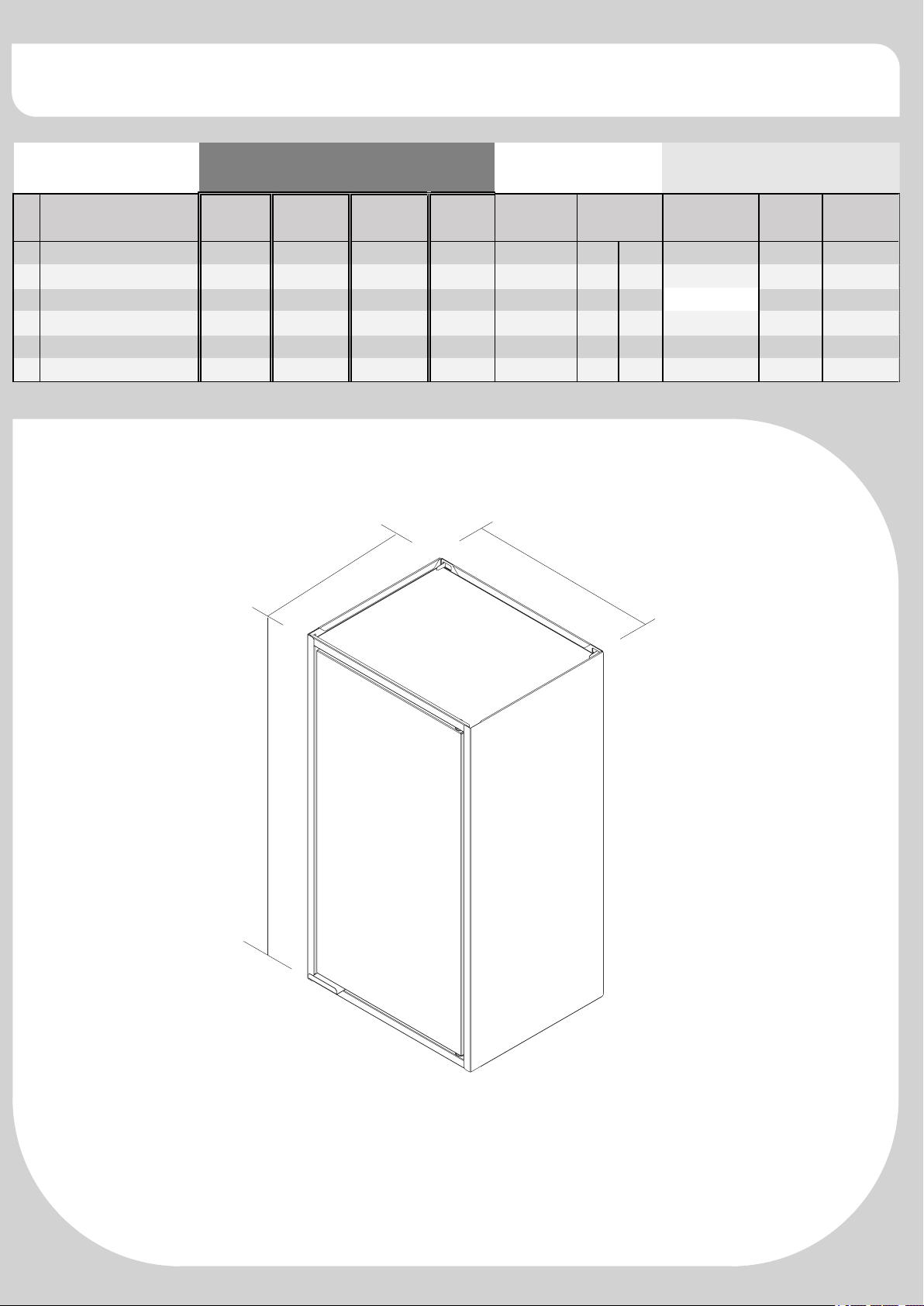
D im ens io n
H
L
W
ASSEMBLED PRODUCT:
H: 25.19'' W:13.77'' L:11.22''
Page 4
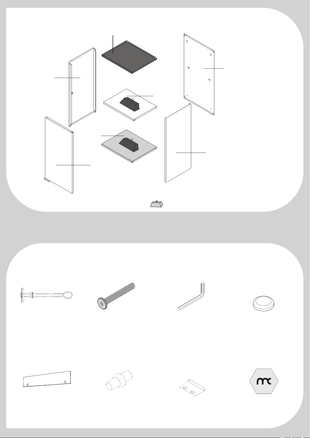
P1
P2
P5
P3
22 Lb
s
22 Lb
s
P4
P6
Maximum weight supported distributed
Lbs
Hardware list
P1
F1
1000008297
Qty. 4
F5
3000008219
Qty. 1
F2
1000008616
Qty. 4
F6
1000010136
Qty. 1
F3
1000009033
Qty. 1
F7
3000009645 - WHITE
3000009643 - BLACK
3000009649 - BLUE
3000009647 - GREY
Qty. 1
F4
1000000281 - WHITE
1000007352 - BLACK
1000010221 - BLUE
Qty. 4
F8
1000008285
Qty. 1
Page 5
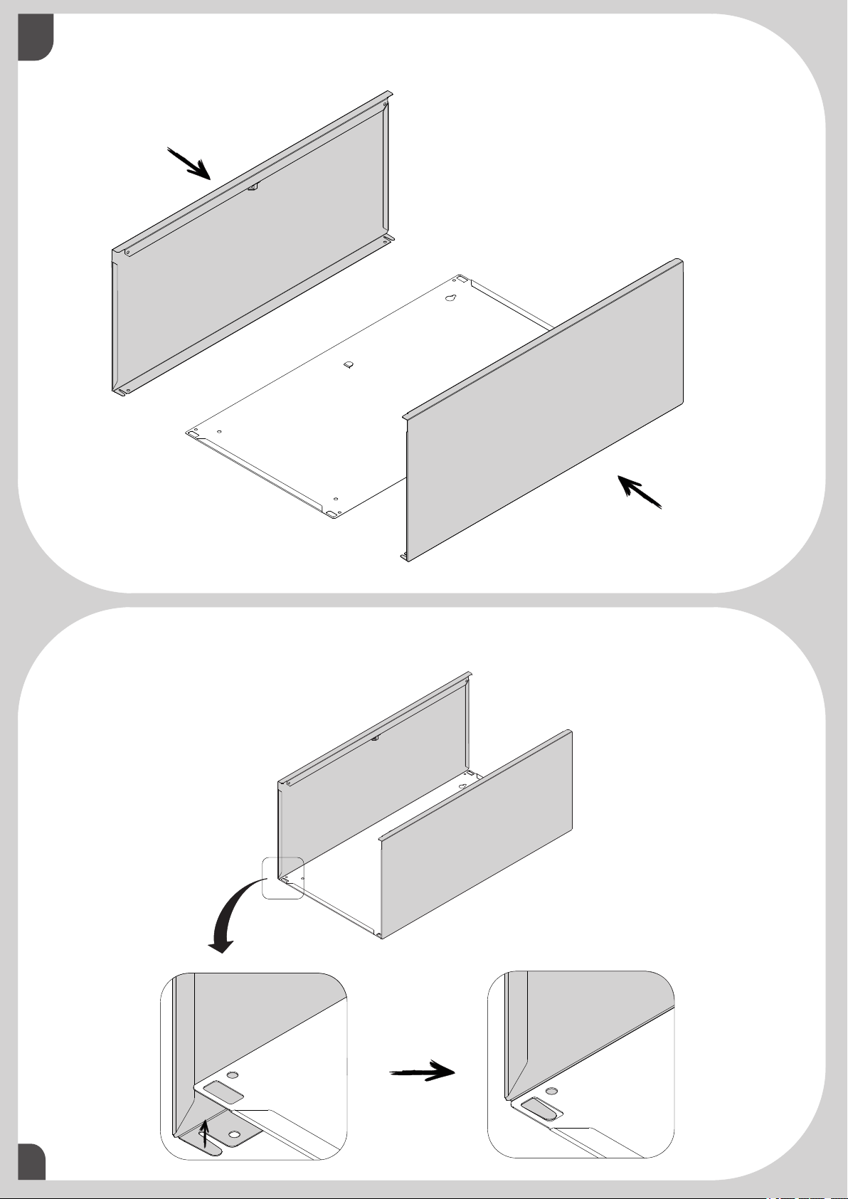
01
1 - Attach the parts P1, under the parts P5.
P1
P5
1 - Position the cut-out of parts P5 over the safety grappel of part P1.
P1
P1
02
P1
P5
Page 6

01
03
1 - Identify the parts as figure below:
P3 with hole and P2 with socket.
P2
P3
1 - Slightly incline the part P3, and place it inside the cut - out of the parts P1.
2 - Slide part P3 into the folds of part P1 and P5.
P3
P3
P1
P3
P1
01
04
P5
Page 7

01
05
1 - With the end of F3, smash the safety claw, locking part P3 to part P1 and P5.
2 - Finish folding it mannually.
P1
P1
P3
P3
P3
F3
1 - Turn the cabinet.
2 - Slightly incline part P2, and position it inside the cutout of parts P1.
3 - Slide part P2 into the folds of part P1 and P5.
P2
P3
P1
P2
01
06
P2
P1
P5
Page 8

01
07
1 - With the end of F3, smash the safety claw, locking part P1 to part P2 and P5.
2 - Finish folding it mannually.
P3
P2
1 - Gently rotate the part P4, and position it inside the cabinet as shown.
2 - Check all the fittings to proceed.
P4
P4
P4
P4
01
08
P5
P5
07
Page 9

01
09
1 - Using the F5 template, make markings on the wall as indicated.
2 - It is necessary to use the level.
3 - Drill the wall over the marked points.
0°
F5
IMPORTANT: CABINET MUST BE ATTACHED TO THE WALL
USE THE CARDBOARD TEMPLATE TO FIX THE WALL CABINET ON THE WALL
IT IS IMPORTANT TO USE A LEVEL
1 - Insert the metal part of the bushing into
the hole until it overcomes the wall.
WALL
CABINET HEIGHT
½”
F5
1X
2 - Pull the bushing driving it against the wall
and then push the plastic ring until it leans close
to the wall.
WALL
Plastic ring
F1
2X
3 - Break the bushing's rods
01
10
WALL
1
WALL
2
WALL
Page 10

01
11
1- Insert the screw F2 into the hole on the wall.
2- Turn the screw clockwise, using the F3 part .
2x
F2
F3
11
1- Approach the cabinet by fitting the F2 screw.
F2
2X
F3
1X
01
10
Page 11

13
01
1 - Align the cabinet with the use of a level.
2 - Mark the wall through the holes in the bottom of the cabinet.
0°
1 - Move the cabinet away
2 - Drill the wall over the marked points.
½”
01
14
Page 12

01
15
1 - Insert the metal part of the bushing into
the hole until it overcomes the wall.
2 - Pull the bushing driving it against the wall
and then push the plastic ring until it leans close
to the wall.
F1
2X
3 - Break the bushing's rods
WALL
WALL
1
2
Plastic ring
WALL
WALL
WALL
1 - Position cabinet through the F2 screws that are already attached to the wall.
14
2 - Insert screw F2 through part P5.
3 - Turn the screw using the F3 part clockwise.
2x
F2
F3
01
16
F2
2X
F3
1X
Page 13

01
17
1 - Press part F4 against the heads of the F2 screws.
4x
F2
F4
18
17
F4
4X
F7
01
18
P6
F7
CLICK !
F7
1X
Page 14

01
19
1 - Attach part P6 to the bottom of the cabinet through part F7
2 - Finish engaging part P6 through the pivoting wrench as shown below.
P6
P6
P6
F6
1X
1 - Glue the sticker F8 in the lower right as indicated.
F6
F8
01
20
P6
F8
1X
Page 15

TAKING GOOD CARE OF YOUR CABINET
Cleaning and caring instructions:
- Avoid dragging objects on top of the cabinet. They might scratch the
finishing.
- Only non-abrasive natural chemical products are recommended to
clean your cabinet. Simply wipe the cabinet down with a wet cloth to
remove the cleaning product excess.
- Never clean the cabinet with scouring powders, steel scrubber pads
or any other product which can scratch its surface.
- Chemical products are not recommended.
- Cabinet surfaces should not be covered with colored plastic or paper
sheets.
- Acid substances like salt, onion, ketchup and mustard must remain
properly stored in sealed containers.
- Avoid the direct contact of water with other surfaces than the sink, as
the humidity can affect the durability of the cabinets.
- Avoid cabinets exposure to direct Sun light. Drapers suggested.
- For technical assistance outside Brazil, please, contact the store
where you purchased your product.
- This guidance should be saved for future reference, if necessary.
BEWARE: Do not use a damp cloth to clean the cabinet. Excessive
moisture can damage its surface.
ATTENTION
To avoid serious or irreparable damage to the product, follow the instructions carefully.
Page 16

WARRANTS TERMS
This product has the guarantee for a period of twelve (12) months, this limited warranty is effective
from the date of the original consumer purchase. Proof of original purchase date is required to obtain
service or replacement under this limited warranty. Once the defect of manufacture has been verified,
the consumer should contact the store where he purchased the product. In the warranty period, any
defective parts will be replaced free of charge by another of the same line and model. The installation
and assembly in the residence of the costumer is not the responsibility of the factory or the store. The
assembly must correctly follow the instructions inside the packaging of each module.
ITEMS EXCLUDED FROM WARRANTS
This limited warranty does not cover:
1. In-home service including, but not limited to, service calls to correct the installation of any
Manhattan Comfort Smart Diy products or to instruct the consumer on how to use or install them.
2. Damage resulting from improper handling or shipping of products, or products damaged by
accident, alteration, misuse, abuse, fire, flood, improper installation, acts of God, neglect, corrosion,
modification or mishandling.
3. All travel, transportation, shipping or freight fees to deliver replacement products or to return
defective products.
4. Factory specified replacement parts or product replacement when your product is used in other
than normal, single-family household use, such as a commercial environment or handled in a manner
contrary to published user or operator instructions and/or installation instructions.
5. Aesthetic damages including scratches, dings, dents or cracks that do not affect the structural or
functional capability of the product.
6. Any labor costs during the limited warranty period.
7. Damage resulting from improper loading beyond the specified maximum weight capacity outlined
in the assembly instructions provided with the product including overloading of hooks, baskets,
shelves, cabinets, and other Manhattan Comfort Smart Diy accessories used with the product.
8. Surfaces damaged due to chemical interaction resulting in corrosion of paint or metal.
The cost of repair or replacement under these excluded circumstances shall be borne by the
customer.
DISCLAIMER OF IMPLIED WARRANTY
Implied warranties, including any implied warranty of merchantability or implied warrant of fitness for
a particular purpose, are limited to one year or shortest period allowed by law.
LIMITATION OF REMEDIES; EXCLUSION OF INCIDENTAL AND CONSEQUENTIAL
DAMAGES
Your sole and exclusive remedy under this limited warranty shall be product repair as provided
herein. Manhattan Comfort Smart Diy shall not be liable for incidental or consequential damages.
 Loading...