

Page 1

Page 2

INDEX
GENERAL SAFETY REQUIREMENTS
CONNECTORS AND DEFINITION
FRONT PANEL CONTROLS
REMOTE CONTROL FUNCTIONS
INSTALLATION
PROGRAMMING THE RECEIVER
TUNING SERVICES FIRST TIME
WEDGING/ADJUSTING ANTENNA
EDITING THE CHANNEL LIST
ADJUSTING OUTPUT SIGNAL TO TV
2
3
3
3
4
5
5
5
6
8
ACCESSING THE EPG (Electronic
Program Guide)
TIMER PROGRAMMING FOR VCR
PARENTAL CONTROL
SELECTING RADIO CHANNELS
RESETTING THE RECEIVER
ASSISTANCE AND ADVICE
GLOSSARY
MULTIPLEXES & CHANNELS
GENERAL SPECIFICATIONS
8
9
10
10
10
11
12
13
16
INTRODUCTION
Please read this manual and the following general safety requirements carefully before
installing the receiver. If you come across a word that you do not understand, please
refer to the Glossary at the end of this manual.
The Plaza DT-100 is a high performance Digital Terrestrial Television (DTT) Receiver,
supporting various requirements of broadcast standards. This receiver includes the best
possible features together with the most up-to-date electronics hardware and easy to use
on-screen menu.
GENERAL SAFETY REQUIREMENTS
Remember that contact with 230V AC mains can be lethal or can cause severe electric
shock. To avoid this risk please follow below instructions
This product is to be operated indoors only. Do not expose the receiver to rain
or moisture.
Do not place your receiver close to sources of heat, such as heater and direct
sunlight.
Never remove the top cover of the receiver. There are no user serviceable
parts inside. Refer all servicing to qualified service agents.
Disconnect the power before connecting or disconnecting anything.
Do not place anything on your receiver that might drip or spill onto it. Never
place the product near objects filled with water.
Do not obstruct the ventilation slots of the receiver. Do not place the receiver on
soft furnishings or carpet. Maintain a free airflow around the receiver.
Do not use solvents of any kind to clean the receiver, only use a soft-dry cloth.
CONNECTORS AND DEFINITIONS
Please do not connect power to the receiver until all other connections have been made.
2
Page 3

C1: TO TV Connect this output to UHF input of your TV. This will allow you to tune your
1: 0~9 To enter the channel number you wish to view
in normal use or to enter digital values when
programming.
2: STBY To switch receiver on or to standby.
3: MENU To enter the main menu or to go back to the
previous menu from a sub-menu.
4: Left & Right keys to navigate or modify various
parameters.
5: Up & Down keys to move up or down when in
menu.
6: PAUSE To pause the picture. Second press
resumes normal view.
7: S-T To access the subtitles selection menu. When
you activate the subtitles, they will appear after a
short while.
8: LIST To display the channel list.
9: AUDIO To select an alternative audio track.
10: EXIT To exit all menus and go back to the
channel you were watching.
11: MUTE Press once to stop the sound. Press it
again to restore the sound.
12: OK To validate a choice in the menus.
F1: Power on/off
button.
F2: CHANNEL Channel
up/down buttons.
F3: Status indicators.
Red when the product is
on standby. Green when
it is switched on.
TV to analogue terrestrial programs as well as to use the built-in modulator for viewing
the digital terrestrial programs.
C2: ANT LOOP IN TV aerial input to modulator.
C3: VIDEO Composite video output to connect to TV or AV monitor etc.
C4: AUDIO LEFT/RIGHT Audio outputs for connecting to a HI-FI system or to the TV
audio input.
C5: RS232 Connector for upgrading software via PC. Use NULL MODEM (female to
female) cable to connect to your PC.
C6: ON – OFF Main power on/off switch.
C7: ANT IN Terrestrial antenna input.
C8: ANT LOOP OUT If you want to use loop through, connect this output to ANT LOOP
IN connector.
C9: TV SCART RGB, CVBS and Audio L & R SCART output to connect to TV.
C10: VCR SCART Connect VCR or DVD player via a SCART cable to this connector.
C11: S/PDIF To connect your receiver to digital audio amplifier.
C12: Power Cord.
FRONT PANEL CONTROLS
REMOTE CONTROL FUNCTIONS
3
Page 4

13: TV/R To select TV or Radio mode.
A: Shows Screened CO-AXIAL cable for your
TV antenna. Replace this in case of poor
reception with a high quality cable.
B & C: By connecting the Modulator output
(B) TO TV to your TV and (C) LOOP OUT to
LOOP IN on the receiver, you will keep the
analogue channels on your TV. You can then
record a digital channel whilst watching
another analogue channel on your TV.
Connecting to TV via the TV SCART (C9)
For clear picture quality, connect receiver to
your TV with a full SCART cable. Select AV
input on your TV.
14: FAV To access favorite list. Press several times to select the correct FAV list if you
have defined more than one. To exit the FAV mode, go to Menu / Favorites and select
OFF
15: EPG (Electronic Programs Guide) To view the program event details playing at the
time and the following ones.
16: Page Up & Down keys to select next page in the lists.
17: TEXT Displays the digital Tele-text service, if available.
18: Color keys to navigate in the digital Tele-text if broadcasted by the service
provider. The red key launches the digital Tele-text, if available.
19: AV To switch AV mode on or off for the TV. It allows you to view an analogue
channel on your TV whilst recording a digital channel from your receiver.
20: INFO To display information (channel name, program, next program etc) on the
current channel you are watching.
21: M/P To display a multi channel screen.
22: Volume UP & Down keys to adjust the sound volume.
The remote control requires two AAA 1.5V batteries. Ensure that these are fitted
correctly. Please do not dispose of used batteries in your domestic waste bins. You may
take them back to your point of sale and place them in the right container.
INSTALLATION
Connect the TV antenna directly to the ANT input of the receiver. Connect the TV using
SCART cable to the TV SCART outlet of the receiver (see below). Switch on the TV and
connect the receiver to the main source. Switch on the main power switch on rear panel
(C6) a red indicator appears on the receiver. Press STBY key on remote to switch on the
receiver, the red indicator will turn green and the welcome screen appear on the TV.
If this is not the case, please double-check the TV SCART connections and select the
correct A/V or EXT mode of your TV (refer to your TV manual).
Connecting to TV via the TO TV (Modulator output C1)
Connect to your TV with a UHF (co-axial) cable and switch on the receiver. Select a spare
channel on your TV and tune it to channel 64 or until you see the welcome screen. Finally
store the setting on your TV. The receiver is factory set to channel 64. To change the
output channel, see ADJUSTING OUTPUT SIGNAL TO TV on page 8.
4
Page 5

Connecting to VCR
Connect your VCR to the VCR SCART on your
receiver.
If the search has not found all the available channels
in your area, it probably means that you need to
better the installation. See next paragraph.
If no channels are found, it probably means that your
area may not be covered by the transmission or the
antenna is not pointing to the digital transmitter. See
next paragraph.
PROGRAMMING THE RECEIVER
Programming the receiver is achieved through the various menus. In order to simplify
this, we will describe accessing a menu as below.
Press MENU key to access the main menu.
Press Down key to highlight Setup.
Press OK to confirm.
Press Down key to highlight Service Setup.
Press OK to confirm.
Enter the 4 digits PIN code (0000 on purchase).
Press Up/Down key to highlight a scan option (example; Full Scan Add New
Services).
Press OK to start the channel search. Following screen will appear showing the search
progress.
TUNING SERVICES FIRST TIME
After the welcome screen appears on the TV, press OK to start the automatic channel
search. Below screen will appear showing the search progress. When the search is
finished, the first channel will appear.
WEDGING / ADJUSTING THE ANTENNA
If no channels are found through your current antenna, it means that, it is probably
pointing towards an analogue only transmitter. If your area is covered by digital, it
means that the programs are coming from another transmitter. Hence you will have to
5
Page 6

adjust the antenna. See following options.
1. Go to Menu / Setup / Service Setup / enter PIN
/ Manual Scan.
2. Press Left/Right key to select the channel number
of the UHF network that transmits digital channels
(see channels list on page 13).
3. On Tx Mode, select 2K with the Left or Right key.
4. On Guard Interval, select 1/32 with the Left or
Right key.
5. Wait for a few seconds and monitor the Level and
Quality graphs.
Option 1
If you know at least one network between channel 21 and 69 is used in your area follow
below setup.
6. Realign the antenna for maximum Level/Quality reception. When aligned correctly to
the transmitter, the Signal Level and Quality should increase. On the Quality, 6 is
minimum number for a stable image. If the Level does not increase, it means that you
have selected an incorrect network number, or the transmitter is too far from your
antenna.
7. Once you have achieved the maximum Level / Quality, fix the antenna position firmly.
8. Press EXIT.
9. Go to Menu / Setup / Service Setup / enter PIN / Full Scan Replace Existing
Services.
10. Press OK to start scan.
Option 2
You are able to receive national channels in analogue, but have no idea what you can
receive in digital quality or if you are certain that you can receive additional channels,
but you do not know which network is used for these channels, we advise that you do
the following.
Install a UHF antenna with high gain (at least 15 dB) and connect it to the ANT input of
the receiver. Adjust the antenna so it is in the same position as the previous one and
start an automatic channels search. (Go to Menu / Setup / Service Setup / enter PIN
/ Full Scan Replace Existing Services).
If you find channels that you were unable to receive with your previous antenna, simply
replace it with the new one. Otherwise align the antenna 1/8 of a turn and start another
automatic search. Continue this process until you find at least a few channels.
1. Select one of the new channels received.
2. Go to Menu / Setup / Service Setup /enter PIN/ Manual Scan.
3. At the bottom of the screen, observe the signal level and quality.
4. Align the antenna to optimize the level and quality (quality must be at least 6).
5. Fix the antenna firmly.
6. Press Menu to go back to the previous menu.
7. Perform an automatic search (Go to Menu / Setup / Service Setup / enter PIN /
Full Scan Replace Existing Services).
EDITING THE CHANNEL LIST
There are two ways of editing the channel list. The first is to create Favourite channels.
6
Page 7

The second is to delete, move or rename existing channels.
1. Go to Menu / Favourites. The first line indicates
OFF, meaning that the favourites mode is inactive.
2. Press the green key to create a list and then the
yellow key to edit its content. The screen will change
to EDIT FAVOURITES with the main channel list on
left and favourites list on right.
3. Use the Up & Down keys to highlight a channel and
press OK to add to your Favourite list.
4. Press EXIT when you have finished.
1. Go to Menu / Favourites.
2. Use Up / Down keys to highlight the list you wish
to rename.
3. Press the yellow key and then the Right key
followed by yellow key again. EDIT keyboard will
appear.
4. Go to Delete using the Up / Down / Left / Right
keys and press OK to delete the letters on current
name.
Creating Favoruite channels list
NOTE: A FAV list may contain TV and Radio services together.
Selecting a Favourite channel
Go to Menu / Favourites then using Up / Down keys, highlight a list that you have
created. Press OK and the menu will close meaning you have selected a list. Press Up /
Down keys to select the required channel. You will remain in the Favourite list until you
exit this list via the menu or change the list via the FAV key.
To exit the Favourite channel list, go to Menu / Favourites and highlight the first line
OFF and press OK.
Renaming a Favourite list
5. Use the Up / Down / Left / Right keys to select one by one the letters and press OK
for every letter.
6. After renaming press green key to store the settings. Finally press EXIT
Editing the contents of a Favourite list
1. Go to Menu / Favorites.
2. Use the Up / Down keys to select the list you wish to edit.
3. Press the yellow key and then the Right key.
4. Highlight the channel you wish to delete.
5. Press the red key to delete the channel.
6. To move a channel, highlight it and press green key. Choose a new place for it with
the Up / Down keys and press OK to confirm. Press EXIT to quit.
Deleting channels
1. Go to Menu / Service Organiser.
2. Use the Up / Down keys to select the channel you wish to delete.
3. Press the red key. You are then requested to enter the PIN to allow service deletion.
4. Enter your PIN code (0000 on purchase).
7
Page 8
5. Press EXIT to quit.
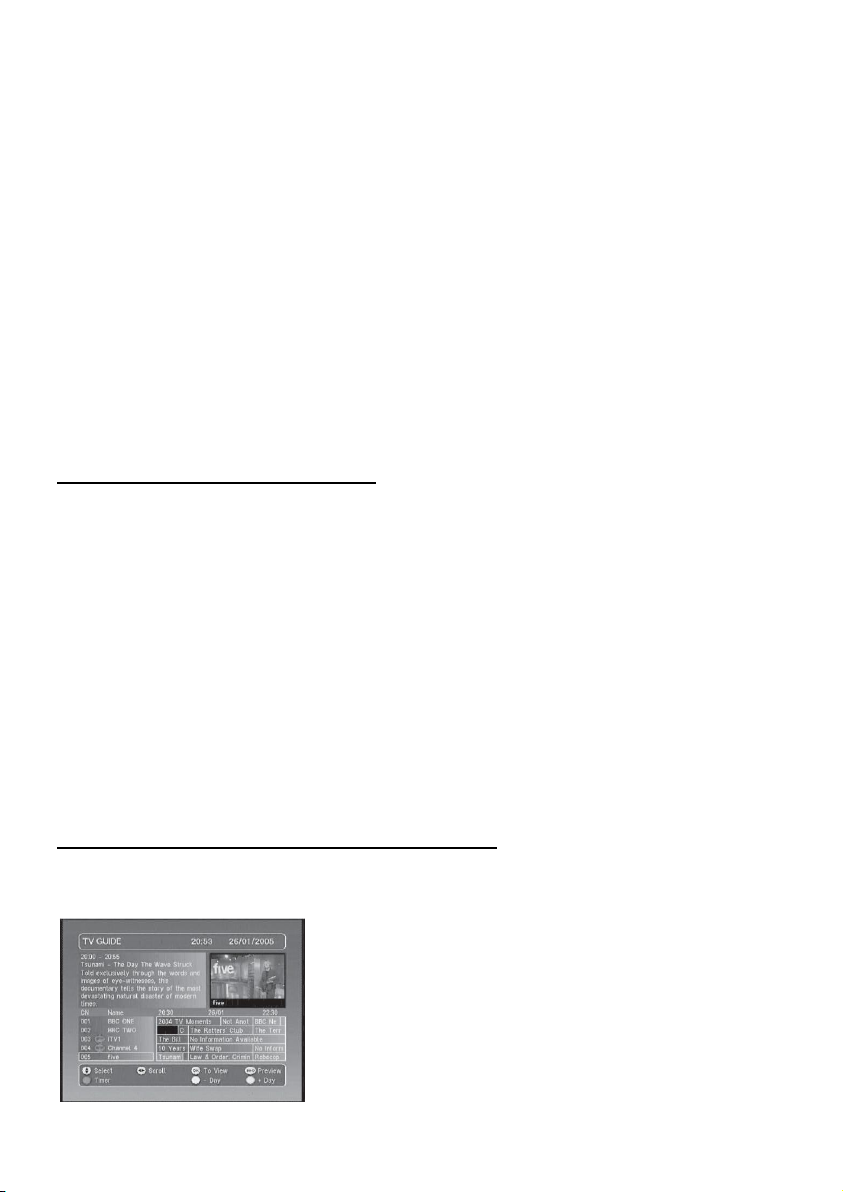
The name of the program playing at the time appears
in orange in the middle right window. You can select
the following program with the Left / Right keys. A
description of the program selected appears in the
top left window.
Moving channels
1. Go to Menu / Service Organiser.
2. Use the Up / Down keys to select the channel you wish to move.
3. Press the green key and move the channel to the required position with the Up / Down
keys.
4. Press OK to confirm the new position.
5. Press EXIT to quit.
NOTE: The channel will keep its logical number.
Renaming a channel
1. Go to Menu / Service Organiser.
2. Use the Up / Down keys to select the channel you wish to rename.
3. Press the yellow key to view the keyboard.
4. Go to Delete using the Up / Down / Left / Right keys and press OK to delete the
current name.
5. Use the Up / Down / Left / Right keys to select one by one the letters and press OK
for every letter.
6. Press the green key to store the settings.
7. Press EXIT to quit.
ADJUSTING OUTPUT SIGNAL TO TV
1. Go to Menu / Setup / TV Setup.
2. On Television type, select 4:3 or 16:9 depending on your screen format.
3. On Widescreen option if you have a 4:3 screen, you can choose on the way a 16:9
image will appear on your TV. See below.
a) The Center Cutout mode increases the image size without distorting it to fill
the whole screen.
b) The Full Frame mode resizes the image horizontally in a 4:3 screen. The image
is therefore distorted.
c) The Letterbox mode shows a full image, with black strips at the top and
4. On Standard, choose between RGB and CVBS. The CVBS mode (composite) gives an
image of lower quality than the RGB, but is compatible with all TVs.
5. On UHF Standard choose PAL I (for UK)
6. On UHF Channel, if you are using the UHF connection and you are getting some
interference on the picture, select a different channel and retune your TV to the new
channel.
ACCESSING THE EPG (Electronic Program Guide)
Pressing the EPG key will allow you to access the details of current and next program
playing for that channel as well as details for other channels.
bottom of the screen.
8
Page 9

1. Go to Menu / Timer Programming. This menu,
lists the programs to be recorded.
2. To program a new recording, press OK on an
empty line the menu will change. See following.
3. On CN, select the channel you wish to record using
the Left / Right keys.
4. On Date, enter the date of the program with the
0~9 keys.
5. On Time, enter the time at which the program
starts.
6. On Duration, enter the duration (hours &
minutes) of the program.
Select another channel using Up / Down keys and you can pre-view its program details in
the top left window and then by pressing the INFO key you can also view the picture for
that channel in the top right window. Press OK if you wish to change to this channel or
press EXIT to go back to previous channel.
The blue key allows you to view the following days programs (as long as the information
is being transmitted). Use the yellow key to go back on day.
When a program has been selected, you can press the red key to enter the information
details directly in the recordings Timer Programming. If you press the red key for a
program that is playing at that time, the recording will start and you must confirm all
changes by pressing EXIT.
If the selected program has not started yet, you can press the green button to activate a
reminder on this program. A reminder will appear regardless of what channel you are
watching.
TIMER PROGRAMMING FOR VCR
Programming
7. On Repeat, select No if this is a one off recording, Weekly if you wish to record on
the same day every week, or Daily if to be recorded every day at the same time.
8. On Subtitles, select Yes or No depending whether you wish to record these as well.
9. Press OK to store the settings.
You must then program your VCR in the similar way so that it starts recording at the
same time. When recording on your VCR, remember that you have to select AUX or EXT
input on the VCR that shows the corresponding channel you have selected on the
receiver. Please refer to your VCR manual if necessary.
9
Page 10

NOTE: If you switch on the receiver whilst a program is supposed to be recorded, you
will be requested to confirm any changes by pressing EXIT. You cannot record a channel
other than the one you are watching.
To playback a VCR tape, the receiver should be on standby. Simply insert the tape and
start playing. The image will appear on the screen. If this is not the case, press the
TV/VCR key on your VCR remote.
PARENTAL CONTROL
Your receiver is supplied with a Factory default code (PIN) that is 0000. This code
allows you to lock channels that you do not wish others to access, or to protect the
settings of the receiver. We advise you to change this code.
Modifying the PIN code
1. Go to Menu / Setup / Parental Control.
2. Enter the 4-digits code 0000.
3. Select Change PIN and press OK. Menu will change.
4. Enter the new 4-digits code using the 0~9 keys.
5. Enter this code once more.
6. Press EXIT to quit and save the settings.
IMPORTANT! Please keep your PIN code safe incase you forget your PIN code. You will
require this for accessing the menus in future.
Locking channels
1. Go to Menu / Setup / Parental Control / enter PIN
2. On Lock/Unlock Services press OK, channel list will appear.
3. Use Up / Down keys to highlight the channel you wish to lock.
4. Press OK and a lock symbol will appear next to the channel.
5. Press EXIT to quit and store the settings.
Censorship (Moral level)
The Censorship parameter in the menu allows you to adjust an age limit. The standard
value is OFF (no limits). To change, press Left / Right keys. If you change to a new limit,
the PIN code will be requested to view the program that the operator decides can only be
viewed by people older than the existing limit.
SELECTING RADIO CHANNELS
Apart from TV channels, terrestrial digital also allows you to receive radio channels. As
soon as you press the TV/R key, you enter the radio mode. From then on, the Up /
Down keys will allow you to select from one radio channel to another. To go back to the
TV mode, press TV/R key again.
RESETTING THE RECEIVER
Follow this process if you have modified the settings and hence the receiver has become
inoperative or is showing unexplainable problems. Resetting the receiver means that you
will lose all the settings you have made including Favorites, Parental lock etc.
1. Go to Menu / Setup / Service Setup / enter PIN / First Time Setup.
2. Enter your PIN code again and confirm by pressing OK.
10
Page 11

3. The menu will disappear and after this the receiver will re- initialize and the welcome
Symptom
Possible Cause
Solution (to try)
You receive analogue
channels without a
problem, but not the
digital channels.
Antenna is pointing to an
analogue only transmitter.
Digital channels may be on
a different transmitter.
Adjust the orientation of
your antenna see
Wedging / adjusting
the antenna
You receive analogue
channels without a
problem, but not the
digital channels. You live
in a flat
The installation of collective
antenna is not adapted to
terrestrial digital
Contact the flat owner or
the residence union
You receive analogue
channels without a
problem, but not the
digital channels.
Your area is not covered by
the digital terrestrial yet.
There is no immediate
solution.
page will be displayed.
4. The receiver is now back in its original Factory Default configuration.
5. Press OK to start the full scan of the channels again.
ASSISTANCE AND ADVICE
FREEVIEW™ coverage
Check FREEVIEW coverage in your area by texting your postcode followed by
your house number or name to 83331* or go to www.freeview.co.uk
(*e.g. NW9 6NY 1, costs no more than a normal text)
What to do if you experience a reception problem
To help you figure out the problem you have come across, it is useful for you to obtain
more information on the locations of the digital transmitters, as well as the UHF networks
that are used.
IMPORTANT! If you experience a problem with the digital terrestrial reception, it is
necessary to define as clearly as possible the symptom of the occurring problem.
In the table below, you will find various solutions for problems you may come across.
11
Page 12

Some channels are not
received at all. The
channels you are receiving
do not have adequate
signal and quality levels.
The picture on analogue
channels is not clear.
You are located far away
from the transmitter.
1.Try an indoor amplifier
2.Try a mast amplifier
3.Try a high gain
antenna.
You receive all digital
channels but the reception
is disrupted at times (i.e.
when another electrical
product is switched on).
You are experiencing
electrical interference.
1. Replace the antenna
cable with a screened
cable.
2. Replace the
accessories (splitters etc)
with screened type.
You are receiving some
networks but others are
disrupted or not received
at all.
You are experiencing
echoes.
1. Slightly adjust the
antenna.
2. Replace the antenna
with Anti-Echoe Screens.
You receive some
networks but others above
channel 60 are disrupted
or not received at all.
Your antenna has high loss
for the upper UHF band.
You need a more
powerful antenna for the
whole UHF band.
You receive networks
between 21 and 35 but
none of those between 36
and 39.
Your antenna only receives
one part of the UHF band
You need a more
powerful antenna for the
whole UHF band.
Your reception is fine most
of the time but is
disrupted when it rains or
at some other random
moments.
You are on the limit of the
transmitters coverage area.
You need a more
powerful antenna.
What is a disrupted reception in digital?
In digital reception, a disrupted reception results in frozen picture (partially or totally) or
the appearance of mosaic effect. The sound may disappear for a while, or strange effect
can be heard. The consequences are totally different from the consequence in analogue
(snow effect).
What about indoor reception?
The transmission parameters are not optimised for indoor reception. As a consequence,
even though it is possible to receiver Freeview channels with an indoor antenna, it is not
guaranteed. Coverage areas are defined for a roof-aerial. Indoor reception is only
possible at a short distance from the transmitter. Electronic interference from home
12
Page 13

appliances such as washing machines, switches etc often cause fleeting reception
problems when using indoor aerial.
GLOSSARY
Receiver: Equipment that allows you to receive digital TV, like Free To View channels.
Analogue Channels: Nature of the signals used for terrestrial television since the
middle of the 20th Century. Since digital has come along, analogue will disappear
(starting 2008).
Network: Number given to a frequency band. In UHF, networks are numbered from 21
to 69.
Transmitter: Pylon that transmits digital or analogue signals, and towards which your
antenna must be pointed.
EPG: Electronic Program Guide.
FTA: Free To Air = free channels.
Digital: Nature of the signals used in modern transmissions. Digital allow you to view
more channels than analogue. Digital channels have existed for a few years on satellite
and cable. They will replace the terrestrial analogue channels. One channel (e.g. BBC1)
can be transmitted both in analogue and digital.
Polarization: Orientation of the transmitter wave. Most UHF transmissions are
horizontal. The elements of your aerial must therefore be horizontal.
Terrestrial: Refers to transmissions in the air, as opposed to cable or satellite.
MULTIPLEXES & CHANNELS
13
Page 14

CHANNEL LIST
14
Page 15

15
Page 16

16
Page 17

GENERAL SPECIFICATIONS
Input Connector
Output Connector
Co-axial 75 Ohm, IEC 169-2, Female
Co-axial 75 Ohm, IEC 169-2, Male
Input Frequency
470 MHz ~862 MHz (UHF)
Signal Level
-10 ~ –82 dBm
System Memory
Flash
SDRAM
Decoder
Transport Stream
Profile Level
Input Rate
Video Formats
A/V & Data In / Out
TV SCART
VCR SCART
Video
Audio Format
Audio R/L
Digital audio
Data Port
1MB
16MB
MPEG-2 ISO/IEC 13818
MPEG-2 Main Profile @ Main Level
Max. 60 Mbit/s
4:3 / 16:9 Selectable
Video Output (CVBS, RGB). Audio output with Volume
Control (Resolution: 16 bits DAC, Max 2Vrms)
Video Output (CVBS) Video Input (CVBS) Audio
Output (Resolution: 16 bits DAC Max.2Vrms)
RCA / Cinch, Video Output (CVBS)
MPEG Layer I & II, 32 / 44.1 / 48KHz
RCA/Cinch Volume & Mute Control
S/PDIF Output, RCA (IEC958)
RS-232. Transfer rate 115.2 Kbps 9-Pin D-sub male
type
Connectors
75 Ohm, IEC 169-2 Male/Female
Frequency
470 to 850 MHz
Output Channel
CH 21 – 69 for the re-modulator
TV Standard
PAL G, I, K
Preset Channel
CH 64 (software changeable by Menu)
Power Supply
Input Voltage
Type
Power Consumption
AC230~240V, 50Hz
SMPS
Max 10W (Standby 7.3W)
Size (W X H X D)
W 260 mm, H 45 mm, D 200 mm
Weight (Net)
1.8KG
Digital Tuner
RF-Modulator
Physical Specifications
Eurosat® and Manhattan® are registered trademarks of Eurosat Distribution Ltd.
Eurosat reserves the right to alter product specifications without prior notice.
The FREEVIEW service is subject to coverage. An aerial upgrade may be required. The
FREEVIEW word and logo are trade marks of DTV Services Ltd and are used under
licence. © DTV Services Ltd 2002.
17
Page 18

18
 Loading...