

Page 1

Barcode Scanner
Programming Quick Guide
manhattan-products.com
Page 2

Page 3

Programming Menu
V3.8 a
Notice
The manufacturer shall not be liable for technical
or editorial errors or omissions contained herein;
nor for incidental or consequential damages in
connection with the furnishing,performance or use
of use the publication.
Page 4

Contents
Chapter 1 Description
1.1 Notice ....................................................... 3
1.2 Introduction ........................................... 4
1.3 Codes Read ........................................... 4
1.4 Installation .............................................. 4
1.5 Pin Assignment ...................................... 6
Chapter 2 Configuration - General
2.1 Flow Chart ............................................. 8
2.2 Loop of Programming ........................... 9
2.3 Factory Default Settings ........................ 9
2.4 Main Page of Configuration................... 10
Chapter 3 Interface and Reading Mode
Selection
3.1 Interface Selection ................................. 11
3.2 Memory Function .................................... 11
3.3 Reading Mode Selection ........................ 12
Chapter 4 Communication Parameters
4.1 RS232 Mode Parameters ...................... 13
4.2 Keyboard Wedge Mode Parameters..... 15
4.3 Output Characters Parameters ............. 17
4.4 Wand Emulation Mode Parameters...... 19
Chapter 5 Bar Codes & Others
5.1 Symbologies Selection ......................... 20
5.2 UPC/EAN/JAN Parameters ................... 24
5.3 Code 39 Parameters ............................. 26
5.4 Code 128 Parameters ........................... 28
5.5 Interleave 25 Parameters ...................... 30
5.6 Industrial 25 Parameters ....................... 32
5.7 Matrix 25 Parameters ............................ 34
5.8 CODABAR/NW7 Parameters ............... 36
5.9 Code 93 Parameters ............................. 38
5.10 Code 11 Parameters ............................. 40
5.11 MSI/PLESSEY Code Parameters ......... 42
1
Page 5

5.12 Code 2 of 6 Parameters ......................... 44
5.13 LCD 25 Parameters ............................. 46
5.14 Telepen Parameters ............................. 48
5.15 GS1 DataBar (RSS Code) ........................50
Chapter 6 Miscellaneous Parameters
6.1 Language Selection .............................. 52
6.2 Bar Code ID .......................................... 54
6.3 Reading Level ........................................ 57
6.4 Accuracy ............................................... 57
6.5 Buzzer Beep Tone ................................. 57
6.6 LED Control .......................................... 57
6.7 Same Code Delay Reading lnterval ...... 58
6.8 Notebook Function ................................ 58
6.9 Reverse Output Characters .................. 59
6.10 Set Up Deletion ...................................... 59
6.11 Set Up Insertion ................................... 62
6.12 Set Up IR Sensor ................................... 65
Appendix
A. Decimal Value Tables ............................ 67
B. ASCII Tables .......................................... 68
C. Function Key Tables .............................. 72
2
Page 6

Chapter 1 Description
1.1 General
Thank you for purchasing this barcode scanner with
an advanced and versatile decoder.The decoder
works with variety of barcode types,reading devices,
and computer interfaces.It discriminates over twenty
different symbologies automatically.
This menu provides an easy way to configure the
decoding options and interface selections by scanning bar codes listed in the menu.
FCC Approval
This device had been tested in accordance with the procedures and in compliance with Part 15 Subpart B of FCC
Rules. And keeps all requirments according ANSI C63.4 &
FCC Part 15 B Regulation and CISPR22 Class B.
CE Standards
The CE mark as shown here indicates this product had
been tested in accordance with the procedures given in
European Council Directive 2004/108/EC and confirmed to
comply with the Europe Standard EN55022:2006:Class B,
EN 55024:1998+A1:2001+A2:2003,IEC61000-3-2:2006,
IE C61 000 -3- 3:1 995+A1: 200 5,I EC6 100 0-4 -2: 200 1,
IEC61000-4-3:2006,IEC61000-4-4:2004,IEC61000-4-5:
2006,IEC61000-4-6:2001,IEC61000-4-8:2001,IEC61000-411:2004.
3
Page 7

1.2 Introduction
Check the device for damage or defects. If you
ndanyproblems,contactyourvendor.Keep
the packaging and included accessories
shouldyouneedtoreturntheitem.
1.3 Codes Read
UPC/EAN/JAN,Code39,Code39FullASCII,
Code128,Interleave25, Industrial25,Matrix
25,CODABAR/NW7,Code11,MSI/PLESSEY,
Code 93, China Postage, Code 32/Italian
Pharmacy.Othersavailableuponrequest
.
1.4 Installation
1.4.1 Basic Instructions
English: Turn off your PC and disconnect its power
cablefromtheACoutlet.ConnectthescannertoaUSB
portonthePC.PlugthepowercablebackintotheAC
outletandturnonthePC.
Deutsch: Schalten Sie Ihren PC aus und trennen
Sie ihn von der Netzpannung (Netzstecker ziehen).
SchliessenSieden BarcodeScanneraneinemUSB
Anschlussan.VerbindenSiejetztIhrenComputermit
derNetzspannungundschaltenSieihnein.
Français:EteignezvotrePCetdébranchezlecordon
d’alimentation.Branchezlelecteurdecodebarresurle
portUSB.Rebranchezlecordon.
Slovensko:Ugasnitevašračunalnikinodklopitenapajalni
kabelizomrežja.PriklopitečitalecvprostoUSBrežona
računalniku.Priklopitenazajnapajalnikabelinvklopite
računalnik.
Connecting the scanner
Keyboardwedge/RS232C/USB:
Connectthe10-pinRS45maleconnectorto
thebottomofthescanner.Youshouldheara
clickwhenaproperconnectionismade.
4
Page 8

Power supply for RS-232C scanner–
There are 3 ways to supplying the power, use external +5V power supply, use optional power cable
(KBDC) which taking the power from KB wedge or
if the host supports +5V power from pin 9.
Installing the scanner to the Host System –
1. Turn off the host system.
2. Connect the power if needed.
3. Connect to the proper port on the host system.
4. Turn on the host system.
Switching cable –
Before removing the cable from the scanner, it is
recommended that the power on the host system
is off and the power supply has been disconnected
from unit.
1. Find the small “Pin-hole” on the bottom of the
unit.
2. Use a bended regular paperclip and insert the
tip into the hole.
3. You will head a “click”, then gentle on the strainrelief of the cable and it will slide out of the
scanner.
SG/LG Series
SD Series
5
Page 9

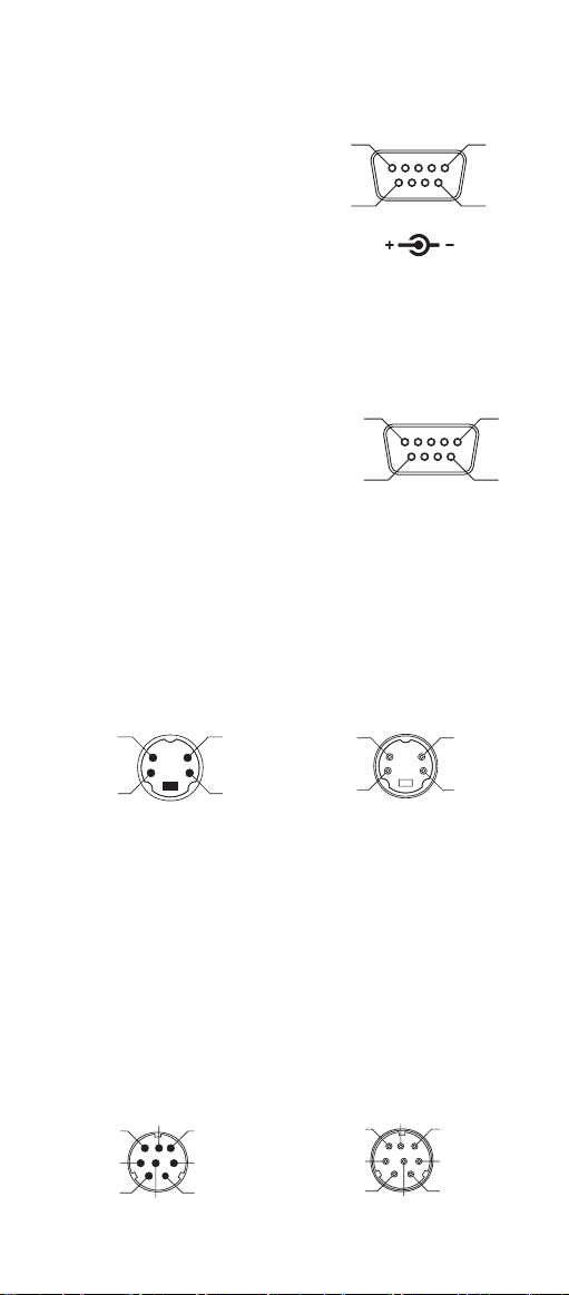
1.5 Pin Assignment
A> Input Port for Mini Decoder
DB 9 Male
Pin No. Wand / CCD /
Slot Reader Laser Scanner
1 N.C. S.O.S.
2 DATA DATA
3 N.C. N.C.
4 N.C. N.C.
5 N.C. TRIGGER
6 N.C. P. E.
7 GND GND
8 SHIELD SHIELD
9 +5V +5V
1
5
6
B> Output Port
1. PC Keyboard Output
DIN 5 MALE DIN 5 FEMALE
Pin No. Function Pin No. Function
1 HOST CLK 1 KB CLK
2 HOST DATA 2 KB DATA
4 GND 4 GND
5 Vcc(+5V) 5 Vcc(+5V)
1
4
MiniDIN 6 MALE MiniDIN 6 FEMALE
Pin No. Function Pin No. Function
1 HOST DATA 1 KB DATA
3 GND 3 GND
4 Vcc 4 Vcc
5 HOST CLK 5 KB CLK
5
3
1
3
5
2
6
4
2
9
3
5
6
4
2
1
4
2
5
3
1
6
Page 10
2. RS-232 Output
DB 9 Female
Pin No. Function
2 TXD
3 RXD
5 GND
7 CTS
8 RTS
Power Lead Vcc (+5V)
3. WAND Emulation Output
DB 9 Female
Pin No. Function
2 DATA
7 GND
9 Vcc (+5V)
4. ADB Interface
MiniDIN 4 MALE MiniDIN 4 FEMALE
Pin No. Function Pin No. Function
1 ADB 1 ADB
3 Vcc 3 Vcc
4 GND 4 GND
5
9
5
9
1
6
1
6
3
1
5. NEC 9801 Interface
MiniDIN 8 MALE MiniDIN 8 FEMALE
Pin No. Function Pin No. Function
1 RST 1 RST
2 GND 3 GND
3 HOST RDY 4 KB RDY
4 HOST DATA 5 KB DATA
5 RTY 4 RTY
8 +5V 5 +5V
7
6
3
1
4
4
2
8
5
2
4
2
8
5
2
7
3
1
7
6
3
1
4
Page 11
Chapter 2 Configuration - General
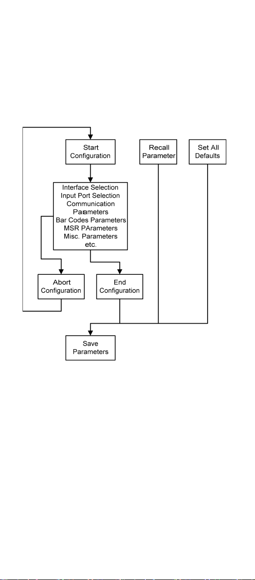
2.1 Flow Chart
8
Page 12

2.2 Loop of Programming
The philosophy of programming parameters has
been shown on the flow chart of 2.1. Basically user
should
1.Scan Start of Configuration.
2.Scan all necessary labels for parameters that meet
applications.
3.Scan End of Configuration to end the programming.
4.To permanently save the settings you programmed
,just scan label for Save Parameters.
5.To go back to the Default Settings,just scan label
for Set All Defaults.
2.3 Factory Default Settings
The factory default settings are shown with <> and
bold in the following sections.You can make your
own settings by following the procedures in this
manual.If you want to save the settings permanently
,you should scan the label of "Save Parameters" in
chapter 2.4,otherwise the settings will not be saved
after the decoder power is off,and all settings will
go back to previous settings.
By scanning "Set All Default" label,the settings will
go back to the factory default settings.
9
Page 13

2.4 Main Page of Configuration
Save Parameters
%$ + / 0
Recall Stored
Parameters
%$ + / 1
Set All Defaults
%$ + / 2
Start Configuration
%$ + / 3
End Configuration
%$ + / 4
Abort Configuration
%$ + / 6
Version Information
%$ + / 5
Save Parameters -
The parameter settings will be saved permanently.
Recall Stored Parameters -
Replace the current parameters by the parameters
you saved last time.
Set All Defaults -
Set all the parameters to the factory default
settings.
Abort Configuration -
Terminate current programming status.
Version Information -
Display the decoder version information and date
code.
10
Page 14

Chapter 3 Interface and
Reading Mode Selection
3.1 Interface Selection
<Keyboard Mode>
%0 0 U0
WAND Emulation
%0 0 M2
RS232 Mode
%0 0 U8
USB Mode
%0 XO8
3.2 Memory Function<HC102M Only>
<Enable>
%0 XI 2
Disable
11
%0 XI 0
Page 15

3.3 Reading Mode Selection
<Good Read OFF>
%0 2 7 1
Continuous/Trigger OFF
%0 2 7 2
Continuous/Auto Power On
%0 2 7 3
Flash/Auto Power On
%0 2 7 6
Reserved 2 ( Auto Sense
Option)
Trigger ON/OFF
%0 2 7 0
Testing
%0 2 7 5
Flash
%0 2 7 4
Reserved1
%0 2 7 7
%0 9 F8
Reserved4
%0 9 FA
Reserved3
%0 9 F9
Reserved5
%0 9 FB
12
Page 16

Ch.4 Communication Parameters
4.1 RS232 Communication Parameters
A> Set Up BAUD Rate
1200
2400
%0 Y7 2
<9600>
%0 Y7 7
38400
%0 Y7 5
B> Set Up Data Bits
7 Data Bits
%0 Y8 0
%0 Y7 1
4800
%0 Y7 3
19200
%0 Y7 4
<8 Data Bits>
%0 Y8 8
C> Set Up Stop Bits
<1 Bit>
%0 YO8
2 Bits
%0 YO0
13
Page 17

D> Set Up Parity
<None>
%0 YN7
Odd
%0 YN3
Space
%0 YN0
E> Handshaking
RTS/CTS Enable
%0 1 8 8
ACK/NAK Enable
Even
%0 YN2
Mark
%0 YN1
<RTS/CTS Disable>
%0 1 8 0
%0 1 4 4
XON/XOFF Enable
%0 3 K4
<ACK/NAK Disable>
%0 1 4 0
<XON/XOFF Disable>
%0 3 K0
14
Page 18

4.2 Keyboard Wedge Mode Parameters
A> Terminal Type
<IBM PC/AT, PS/2>
%0 Z F0
IBM PS/2 25, 30
%0 Z F2
Apple Desktop Bus(ADB)
%0 Z F4
IBM 122 Key (1)
%0 Z F6
IBM 122 Key (2)
%0 Z F8
IBM PC/XT
%0 Z F1
NEC 9800
%0 Z F3
IBM 5550
%0 Z F5
IBM 102 Key
%0 Z F7
Reserved 1
Reserved 2
%0 Z FA
Reserved 4
%0 Z FC
%0 Z F9
Reserved 3
%0 Z FB
Reserved 5
%0 Z FD
15
Page 19

B> Upper/Lower Case
<No Change>
%0 3 3 0
Upper Case
%0 3 3 1
Lower Case
%0 3 3 2
C> Capslock Detection
Enable
%0 X8 8
<Disable>
%0 X8 0
D> Send Character by ALT Method
Enable
%0 3 O8
<Disable>
E>Select Numerical Pad
ON
%0 1 K4
<OFF>
16
%0 3 O0
%0 1 K0
Page 20

4.3 Output Characters Parameters
A> Select Terminator
<CR+LF>
CR
Space
STX-ETX
%7 S2 +
%7 S0 +
%7 S4 +
%7 S5 +
None
%7 S7 +
LF
%7 S1 +
HT(TAB)
%7 S3 +
17
Page 21

B> Time-out Between Characters
<0 ms>
10 ms
50 ms
200 ms
%0 0 7 0
5 ms
%0 0 7 1
%0 0 7 2
25 ms
%0 0 7 3
%0 0 7 4
100 ms
%0 0 7 5
%0 0 7 6
300 ms
18
%0 0 7 7
Page 22

4.4 Wand Emulation Mode Parameters
A> TTL Level Representation
<Bar Equals High>
%0 2 K4
Bar Equals Low
B> Scan Speed Selection
<Fast>
%0 2 8 8
Slow
C> Output Format Selection
<Output as Code 39>
%0 2 O8
Output as Code 39
Full ASCII
%0 2 K0
%0 2 8 0
Output as Original
Code Format
%0 XK4
%0 2 O0
19
Page 23

Ch.5 Bar Codes & Others
5.1 Symbologies Selection
UPC-A <ON>
%0 A4 4
UPC-E <ON>
%0 BO8
EAN-13/JAN-13/ISBN-13
<ON>
%0 A2 2
EAN-8/JAN-8 <ON>
%0 A1 1
CODE 39 <ON>
%0 EO8
OFF
%0 A4 0
OFF
%0 BO0
OFF
%0 A2 0
OFF
%0 A1 0
OFF
CODE 128 <ON>
%0 F O8
CODABAR/NW7 <ON>
%0 J O8
%0 EO0
OFF
%0 F O0
OFF
%0 J O0
20
Page 24

Interleave 25 <ON>
%0 GO8
Industrial 25 ON
%0 HO8
Matrix 25 ON
%0 I O8
CODE 93 ON
%0 KO8
CODE 11 ON
%0 L O8
OFF
%0 GO0
<OFF>
%0 HO0
<OFF>
%0 I O0
<OFF>
%0 KO0
<OFF>
China Postage ON
%0 MO8
MSI/PLESSEY ON
%0 NO8
%0 L O0
<OFF>
%0 MO0
<OFF>
%0 NO0
21
Page 25

Code 2 of 6 ON
%0 PO8
<OFF>
LCD25 ON
%0 QO8
<OFF>
Telepen ON
<OFF>
%0 TO8
Reserved5 ON
%0 RO8
<OFF>
Reserved6 ON
%0 SO8
<OFF>
%0 PO0
%0 QO0
%0 TO0
%0 RO0
22
%0 SO0
Page 26

GS1 DataBar Omnidirectional ON
<OFF>
%0 UO8
GS1 DataBar Limited ON
<OFF>
%0 VO8
GS1 DataBar Expanded ON
<OFF>
%0 WO8
Select All Bar Codes
%1 A/ +
%0 UO0
%0 VO0
%0 WO0
23
Page 27

5.2 UPC/EAN/JAN Parameters
A> Reading Type
UPCA=EAN13 ON
%0 AK 4
UPCA=EAN13<OFF>
ISBN-10 Enable
%0 AK 0
%0 B8 8
ISBN-13 <Enable>
ISSN Enable
%0 B8 0
%0 B4 4
ISSN <Disable>
Decode with Supplement
%0 B4 0
<Autodiscriminate
%0 1 O0
Supplement>
Expand UPC-E
Enable
%0 1 O8
Expand UPC-E
<Disable>
EAN8=EAN13
Enable
%0 BH1
%0 BH0
EAN8=EAN13
<Disable>
GTIN Format
Enable
%0 AO8
%0 AO0
GTIN Format
<Disable>
%0 X4 4
%0 X4 0
24
Page 28

B> Supplementals Set Up
<Not Transmit>
Transmit 2 Code
%0 B3 3
Transmit 5 Code
%0 B3 1
Transmit 2&5 Code
%0 B3 2
%0 B3 0
C> Check Digit Transmission
UPC-A Check Digit
Transmission <ON>
OFF
%0 AI 2
UPC-E Check Digit
Transmission <ON>
OFF
%0 BI 2
EAN-8 Check Digit
Transmission <ON>
OFF
%0 A8 8
EAN-13 Check Digit
Transmission <ON>
%0 AI 0
%0 BI 0
%0 A8 0
OFF
%0 AH1
ISSN Check Digit
Transmission <ON>
OFF
%0 BK4
25
%0 AH0
%0 BK0
Page 29

5.3 Code 39 Parameters
A> Type of Code
<Standard>
%0 EH1
Full ASCII
Italian Pharmacy/Code 32
<OFF>
%0 E8 0
Italian Pharmacy/
Code 32 ON
B> Check Digit Transmission
<Do Not Calculate
Check Digit>
%0 EM2
Calculate Check Digit
& Not Transmit
Calculate Check Digit
& Transmit
%0 EH0
%0 E8 8
%0 EM6
%0 EM4
C> Output Start/Stop Character
Enable
<Disable>
%0 E4 4
%0 E4 0
26
Page 30

D> Decode Asterisk
Enable
%0 E2 2
<Disable>
%0 E2 0
E> Set Up Code Length
To set the fixed length:
1. Scan the "Begin" label of the desired set.
2. Go to the Decimal Value Tables in Appendix A,
scan label(s) that represents the length to be
read.
3. Scan the "Complete" label of the desired set.
Repeat the steps 1 - 3 to set additional lengths.
<Variable>
%4 E1 +
Fix Length (2 Sets Available)
1. 1st Set Begin 2. Decimal Value
(Appendix A)
%4 E0 0
1. 2nd Set Begin 2. Decimal Value
3. 1st Set Complete
%4 E0 1
(Appendix A)
%4 E0 0
3. 2nd Set Complete
%4 E0 2
Minimum Length
1. Begin 2. Decimal Value
(Appendix A)
%2 + - /
3. Complete
%2 C0 +
27
Page 31

5.4 Code 128 Parameters
A> Reading Type
UCC/EAN-128
Enable
<UCC/EAN-128
Disable>
%0 F4 4
<Enable']C1'Code
%0 F4 0
Format>
Disable']C1'Code
Format
<Enable Code128 Group
Separators (GS)>
Disable Code128
Group Separators
(GS)
%0 F2 2
%0 F2 0
%0 F1 1
%0 F1 0
B> Check Digit Transmission
Do Not Calculate
Check Digit
Calculate Check
<Calculate Check Digit
& Not Transmit>
%0 F N1
Digit & Transmit
%0 F N7
%0 F N5
C> Append FNC2
ON
<OFF>
%0 F 8 8
28
%0 F 8 0
Page 32

D> Set Up Code Length
To set the fixed length:
1. Scan the "Begin" label of the desired set.
2. Go to the Decimal Value Tables in Appendix A,
scan label(s) that represents the length to be
read.
3. Scan the "Complete" label of the desired set.
Repeat the steps 1 - 3 to set additional lengths.
<Variable>
%4 F 1 +
Fix Length (2 Sets Available)
1. 1st Set Begin 2. Decimal Value
(Appendix A)
%4 F 0 0
3. 1st Set Complete
%4 F 0 1
1. 2nd Set Begin 2. Decimal Value
(Appendix A)
%4 F 0 0
3. 2nd Set Complete
%4 F 0 2
Minimum Length
1. Begin 2. Decimal Value
(Appendix A)
%2 + - /
3. Complete
%2 C1 +
29
Page 33

5.5 Interleave 25 Parameters
A> Check Digit Transmission
<Do Not Calculate
Check Digit>
%0 GN3
Calculate Check Digit
& Transmit
Calculate Check Digit
& Not Transmit
%0 GN5
B> Set Up Number of Character
<Even>
%0 G8 8
Odd
C> Brazilian Banking Code
%0 GN7
%0 G8 0
<Disable>
%0 G40
Enable
%0 G44
30
Page 34

D> Set Up Code Length
To set the fixed length:
1. Scan the "Begin" label of the desired set.
2. Go to the Decimal Value Tables in Appendix A,
scan label(s) that represents the length to be
read.
3. Scan the "Complete" label of the desired set.
Repeat the steps 1 - 3 to set additional lengths.
<Variable>
%4 G1 +
Fix Length (2 Sets Available)
1. 1st Set Begin 2. Decimal Value
(Appendix A)
%4 G0 0
3. 1st Set Complete
%4 G0 1
1. 2nd Set Begin 2. Decimal Value
(Appendix A)
%4 G0 0
3. 2nd Set Complete
%4 G0 2
Minimum Length
1. Begin 2. Decimal Value
(Appendix A)
%2 + - /
3. Complete
%2 C2 +
31
Page 35

5.6 Industrial 25 Parameters
A> Reading type
IATA25 Enable
<Disable>
%0 H44
%0 H40
B> Check Digit Transmission
<Do Not Calculate
Check Digit>
Calculate Check Digit
%0 HN3
Calculate Check Digit
& Transmit
%0 HN7
& Not Transmit
%0 HN5
C> Set Up Code Length
To set the fixed length:
1. Scan the "Begin" label of the desired set.
2. Go to the Decimal Value Tables in Appendix A,
scan label(s) that represents the length to be
read.
3. Scan the "Complete" label of the desired set.
Repeat the steps 1 - 3 to set additional lengths.
32
Page 36

<Variable>
%4 H1 +
Fix Length (2 Sets Available)
1. 1st Set Begin 2. Decimal Value
(Appendix A)
%4 H0 0
3. 1st Set Complete
%4 H0 1
1. 2nd Set Begin 2. Decimal Value
(Appendix A)
%4 H0 0
3. 2nd Set Complete
%4 H0 2
Minimum Length
1. Begin 2. Decimal Value
(Appendix A)
%2 + - /
3. Complete
%2 C3 +
33
Page 37

5.7 Matrix 25 Parameters
A> Check Digit Transmission
<Do Not Calculate
Check Digit>
%0 I N3
Calculate Check Digit
& Transmit
Calculate Check Digit
%0 I N7
& Not Transmit
%0 I N5
B> Set Up Code Length
To set the fixed length:
1. Scan the "Begin" label of the desired set.
2. Go to the Decimal Value Tables in Appendix A,
scan label(s) that represents the length to be
read.
3. Scan the "Complete" label of the desired set.
Repeat the steps 1 - 3 to set additional lengths.
34
Page 38

<Variable>
%4 I 1 +
Fix Length (2 Sets Available)
1. 1st Set Begin 2. Decimal Value
(Appendix A)
%4 I 0 0
3. 1st Set Complete
%4 I 0 1
1. 2nd Set Begin 2. Decimal Value
(Appendix A)
%4 I 0 0
3. 2nd Set Complete
%4 I 0 2
Minimum Length
1. Begin 2. Decimal Value
(Appendix A)
%2 + - /
3. Complete
%2 C4 +
35
Page 39

5.8 CODABAR/NW7 Parameters
A> Set Up Start/Stop Characters Upon
Transmission
ON
<OFF>
%0 J H1
%0 J H0
B> Transmission Type of Start/Stop
<A/B/C/D> <Start>
A Start
B Start
C Start
D Start
%0 4 VF
%0 4 V1
%0 4 V2
%0 4 V4
%0 4 V8
<A/B/C/D> <Stop>
%0 4 F F
A Stop
%0 4 F 1
B Stop
%0 4 F 2
C Stop
%0 4 F 4
D Stop
36
%0 4 F 8
Page 40

C> Set Up Code Length
To set the fixed length:
1. Scan the "Begin" label of the desired set.
2. Go to the Decimal Value Tables in Appendix A,
scan label(s) that represents the length to be
read.
3. Scan the "Complete" label of the desired set.
Repeat the steps 1 - 3 to set additional lengths.
<Variable>
%4 J 1 +
Fix Length (2 Sets Available)
1. 1st Set Begin 2. Decimal Value
(Appendix A)
%4 J 0 0
3. 1st Set Complete
%4 J 0 1
1. 2nd Set Begin 2. Decimal Value
(Appendix A)
%4 J 0 0
3. 2nd Set Complete
%4 J 0 2
Minimum Length
1. Begin 2. Decimal Value
(Appendix A)
%2 + - /
3. Complete
%2 C5 +
37
Page 41

5.9 Code 93 Parameters
A> Check Digit Transmission
<Calculate Check 2 Digits
& Not Transmit>
%0 KN4
Do Not Calculate
Check Digit
%0 KN3
B> Set Up Code Length
To set the fixed length:
1. Scan the "Begin" label of the desired set.
2. Go to the Decimal Value Tables in Appendix A,
scan label(s) that represents the length to be
read.
3. Scan the "Complete" label of the desired set.
Repeat the steps 1 - 3 to set additional lengths.
38
Page 42

<Variable>
%4 K1 +
Fix Length (2 Sets Available)
1. 1st Set Begin 2. Decimal Value
(Appendix A)
%4 K0 0
3. 1st Set Complete
%4 K0 1
1. 2nd Set Begin 2. Decimal Value
(Appendix A)
%4 K0 0
3. 2nd Set Complete
%4 K0 2
Minimum Length
1. Begin 2. Decimal Value
(Appendix A)
%2 + - /
3. Complete
%2 C6 +
39
Page 43

5.10 Code 11 Parameters
A> Check Digit Transmission
<Do Not Calculate
Check Digit>
%0 L N3
Calculate Check 1
Digit & Transmit
Calculate Check 1 Digit
%0 L N7
& Not Transmit
%0 L N5
Calculate Check 2 Digits
Calculate Check 2
Digits & Transmit
%0 L N6
& Not Transmit
%0 L N4
B> Set Up Code Length
To set the fixed length:
1. Scan the "Begin" label of the desired set.
2. Go to the Decimal Value Tables in Appendix A,
scan label(s) that represents the length to be
read.
3. Scan the "Complete" label of the desired set.
Repeat the steps 1 - 3 to set additional lengths.
40
Page 44

<Variable>
%4 L 1 +
Fix Length (2 Sets Available)
1. 1st Set Begin 2. Decimal Value
(Appendix A)
%4 L 0 0
3. 1st Set Complete
%4 L 0 1
1. 2nd Set Begin 2. Decimal Value
(Appendix A)
%4 L 0 0
3. 2nd Set Complete
%4 L 0 2
Minimum Length
1. Begin 2. Decimal Value
(Appendix A)
%2 + - /
3. Complete
%2 C7 +
41
Page 45

5.11 MSI/PLESSEY Code Parameters
A> Check Digit Transmission
Do Not Calculate
Check Digit
%0 NN3
Calculate Check Digit
& Transmit
<Calculate Check Digit
%0 NN7
& Not Transmit>
%0 NN5
B> Set Up Code Length
To set the fixed length:
1. Scan the "Begin" label of the desired set.
2. Go to the Decimal Value Tables in Appendix A,
scan label(s) that represents the length to be
read.
3. Scan the "Complete" label of the desired set.
Repeat the steps 1 - 3 to set additional lengths.
42
Page 46

<Variable>
%4 N1 +
Fix Length (2 Sets Available)
1. 1st Set Begin 2. Decimal Value
(Appendix A)
%4 N0 0
3. 1st Set Complete
%4 N0 1
1. 2nd Set Begin 2. Decimal Value
(Appendix A)
%4 N0 0
3. 2nd Set Complete
%4 N0 2
Minimum Length
1. Begin 2. Decimal Value
(Appendix A)
%2 + - /
3. Complete
%2 C9 +
43
Page 47

5.12 Code 2 of 6 Parameters
A> Check Digit Transmission
<Do Not Calculate
Check Digit>
%0 PN3
Calculate Check
Digit & Transmit>
Calculate Check Digit
%0 PN7
& Not Transmit
%0 PN5
B> Set Up Code Length
To set the fixed length:
1. Scan the "Begin" label of the desired set.
2. Go to the Decimal Value Tables in Appendix A,
scan label(s) that represents the length to be
read.
3. Scan the "Complete" label of the desired set.
Repeat the steps 1 - 3 to set additional lengths.
44
Page 48

<Variable>
%4 P1 +
Fix Length (2 Sets Available)
1. 1st Set Begin 2. Decimal Value
(Appendix A)
%4 P0 0
3. 1st Set Complete
%4 P0 1
1. 2nd Set Begin 2. Decimal Value
(Appendix A)
%4 P0 0
3. 2nd Set Complete
%4 P0 2
Minimum Length
1. Begin 2. Decimal Value
(Appendix A)
%2 + - /
3. Complete
%2 CB+
45
Page 49

5.13 LCD25 Parameters
A> Check Digit Transmission
<Do Not Calculate
Check Digit>
Calculate Check Digit
%0 QN3
& Transmit
Calculate Check
%0 QN7
Digit & Not Transmit
%0 QN5
B> Setup Code Length
To set the fixed length:
1. Scan the "Begin" label of the desired set.
2. Go to the Decimal Value Tables in Appendix A,
scan label(s) that represents the length to be
read.
3. Scan the "Complete" label of the desired set.
Repeat the steps 1 - 3 to set additional lengths.
46
Page 50

<Variable>
%4 Q1+
Fix Length (2 Sets Available)
1. 1st Set Begin 2. Decimal Value
(Appendix A)
%4 Q00
3. 1st Set Complete
%4 Q01
1. 2st Set Begin 2. Decimal Value
(Appendix A)
%4 Q00
3. 2nd Set Complete
%4 Q02
Minimum Length
1. Begin 2. Decimal Value
(Appendix A)
%2 + - /
3. Complete
%2 CC+
47
Page 51

5.14 Telepen Parameters
A> Type of Code
<Full ASCll Mode>
Compressed Numeric
Mode
B> Check Digit Transmission
%0 T8 0
%0 T8 8
Do Not Calculate
Check Digit
%0 TN3
Calculate Check
Digit & Transmit
<Calculate Check Digit
& Not Transmit>
%0 TN5
%0 TN7
C> Set Up Code Length
To set the fixed length:
1. Scan the "Begin" label of the desired set.
2. Go to the Decimal Value Tables in Appendix A,
scan label(s) that represents the length to be
read.
3. Scan the "Complete" label of the desired set.
Repeat the steps 1 - 3 to set additional lengths.
48
Page 52

<Variable>
%4 T1 +
Fix Length (2 Sets Available)
1. 1st Set Begin 2. Decimal Value
(Appendix A)
%4 T0 0
3. 1st Set Complete
%4 T0 1
1. 2nd Set Begin 2. Decimal Value
(Appendix A)
%4 T0 0
3. 2nd Set Complete
%4 T0 2
Minimum Length
1. Begin 2. Decimal Value
(Appendix A)
%2 %+ - /
3. Complete
%2 CF+
49
Page 53

5.15 GS1 Databar(RSS Code)
A> GS1 DataBar Omnidirectional ON
<Transmit Check
Digit>
Don't Transmit
Check Digit
<Transmit
Application ID>
%0 UN7
%0 UN5
%0 U88
Don't Transmit
Application ID
Transmit Symbology ID
%0 U80
%0 U44
<Don't Transmit
Symbology ID>
%0 U40
B> GS1 DataBar Limited Parameters
<Transmit Check
Digit>
%0 VN7
Don't Transmit
Check Digit
%0 VN5
50
Page 54

<Transmit Application ID>
%0 V8 8
Don't Transmit
Application ID
Transmit Symbology ID
%0 V8 0
%0 V4 4
<Don't Transmit
Symbology ID>
%0 V4 0
C> GS1 DataBar Expanded Parameters
Transmit Symbology ID
%0 W4 4
<Don't Transmit
Symbology ID>
%0 W4 0
51
Page 55

Ch.6 Miscellaneous Parameters
6.1 Language Selection
<US English>
Italian
French
Swedish
%0 Z V0
UK English
%0 Z V1
%0 Z V2
Spanish
%0 Z V3
%0 Z V4
German
%0 Z V5
%0 Z V6
Switzerland
Hungarian
%0 Z V8
%0 Z V7
Japanese
%0 Z V9
52
Page 56

Belgium
Denmark
Turkey
%0 Z VA
Portuguese
%0 Z VB
%0 Z VC
Netherlands
%0 Z VD
%0 Z VE
Reserved2
%0 Z VF
53
Page 57

6.2 Bar Code ID
ON
%0 0 H1
<OFF>
%0 0 H0
Default
%9 1 3 +
With this function ON, a leading character will be
added to the output string while scanning code, user
may refer to the following table to know what kind of
bar code is being scanned.
Please refer to the table below for matching code
ID of codes read in.
Code Type ID Code Type ID
UPC-A A UPC-E B
EAN-8 C EAN-13 D
CODE 39 E CODE 128 F
Interleave 25 G Industrial 25 H
Matrix 25 I Codabar/NW7 J
CODE 93 K CODE 11 L
China Postage M MSI/PLESSEY N
Code 2 of 6 P LCD25 Q
Telepen T RSS-14 U
RSS Limited V RSS Expanded W
User Define Code ID
To set the code ID:
1. Scan the symbologies label.
2. Go to the ASCII Tables in Appendix B, scan
label that represents the desired code ID.
Note:
User define code ID will override default value.
Program will not check the conflict. It is possible
to have more than two symbologies which have
same code ID.
54
Page 58

UPC-A
UPC-E
%9 1 A+
EAN-13/JAN-13
%9 1 Y+
EAN-8/JAN-8
CODE 39
%9 1 E+
CODE 128
CODABAR/NW7
%9 1 J +
Interleave 25
Industrial 25
%9 1 H+
Matrix 25
%9 1 B+
%9 1 Z +
%9 1 F +
%9 1 G+
CODE 93
%9 1 K+
China Postage
%9 1 M+
%9 1 I +
CODE 11
%9 1 L +
MSI/PLESSEY
%9 1 N+
55
Page 59

Code 2 of 6
%9 1 P+
Telepen
%9 1 T+
LCD25
RSS-14
%9 1 Q+
%9 1 U+
RSS Limited
%9 1 V+
RSS Expanded
%9 1 W+
Reserved5
%9 1 R+
Reserved6
%9 1 S+
56
Page 60

6.3 Reading Level
Bar Equals High
%0 3 I 2
6.4 Accuracy
<1 Time>
%0 1 3 0
3 Times
%0 1 3 2
6.5 Buzzer Beep Tone
<High>
%0 1 J 3
Low
<Bar Equals Low>
%0 3 I 0
2 Times
%0 1 3 1
4 Times
%0 1 3 3
Medium
%0 1 J 2
%0 1 J 1
Off
6.6 LED Control(SV700 only)
<ON>
OFF
%0 9 O8
57
%0 1 J 0
%0 9 O0
Page 61

6.7 Sensitivity of Continuous Reading Mode
A> Quick Setting:
<Fast>
Slow
%0 3 8 8
%0 3 8 0
B> Same Code Delay Reading Interval
Following code sequences represent the
length of time before a barcode can be
rescanned at continuous and flash reading
mode. The value can be defined from 1-50
and they represent 100ms to 5 seconds in
100ms interval.Default value is 3 (0.3 seconds).
To setup same code delay reading interval:
1.Scan the "Begin" label
2.Go the Decimal Value Tables in Appendix A,
Scan label(s),that represents the same code
delay reading interval.They are ranged form
1-50.One step is represented 0.1second.So
the interval is from 0.1 to 5 seconds.
3.Scan the "Complete" label
Repeat the steps 1-3 to set time out of same
symbol
1.Begin 2.Decimal Value
(1-50) (Appendix A)
%3 0 0 0 0
3.Complete
%3 0 0 0 1
6.8 Notebook Function
Enable
<Disable>
%0 3 4 4
%0 3 4 0
58
Page 62

6.9 Reverse Output Characters
<Disable>
%0 3 H0
6.10 Setup Deletion
Enable
%0 3 H1
To setup the deletion of output characters:
1. Scan the label of the desired set below.
2. Scan the label of the desired symbology.
3. Go to the Decimal Value Tables in Appendix A,
sc an label(s ) t hat represe nts the desired
position to be deleted.
4. Scan the "Complete" label of "Character Position
to be Deleted".
5. Go to the Decimal Value Tables in Appendix A,
scan label(s) that represents the number of
characters to be deleted.
6. Scan the "Complet e" label o f "Nu mber of
Characters to be Deleted".
Repeat the steps 1 - 6 to set additional deletion.
A> Select Deletion Set Number
1. 1st Set
3. 3rd Set
5. 5th Set
%8 0 0 +
%8 0 2 +
%8 0 4 +
2. 2nd Set
%8 0 1 +
4. 4th Set
%8 0 3 +
6. 6th Set
%8 0 5 +
59
Page 63

B> Symbologies Selection
UPC-A
%8 1 A+
EAN-13/JAN-13/ISBN-13
%8 1 Y+
CODE 39
%8 1 E+
CODABAR/NW7
%8 1 J +
Industrial 25
%8 1 H+
UPC-E
%8 1 B+
EAN-8/JAN-8
%8 1 Z +
CODE 128
%8 1 F +
Interleave 25
%8 1 G+
Matrix 25
CODE 93
%8 1 K+
China Postage
%8 1 M+
%8 1 I +
CODE 11
%8 1 L +
MSI/PLESSEY
%8 1 N+
60
Page 64

Code 2 of 6
Telepen
LCD25
%8 1 T+
RSS-14
RSS Limited
%8 1 U+
RSS Expanded
All Codes
%8 1 W+
None
%8 1 4 +
C>
Character Position to be Deleted
%8 1 P+
%8 1 Q+
%8 1 V+
%8 1 S+
1. Decimal Value
(Appendix A) 2. Complete
%8 2 0 +
D>
Number of Characters to be Deleted
1. Decimal Value
(Appendix A) 2. Complete
%8 3 0 +
61
Page 65

Page 66

B> Symbologies Selection
UPC-A
%5 1 A+
EAN-13/JAN-13/ISBN-13
%5 1 Y+
CODE 39
%5 1 E+
CODABAR/NW7
%5 1 J +
Industrial 25
%5 1 H+
UPC-E
%5 1 B+
EAN-8/JAN-8
%5 1 Z +
CODE 128
%5 1 F +
Interleave 25
%5 1 G+
Matrix 25
CODE 93
%5 1 K+
China Postage
%5 1 M+
%5 1 I +
CODE 11
%5 1 L +
MSI/PLESSEY
%5 1 N+
63
Page 67

Code 2 of 6
Telepen
LCD25
%5 1 T+
RSS-14
RSS Limited
%5 1 U+
RSS Expanded
All Codes
%5 1 W+
None
%5 1 4 +
%5 1 P+
%5 1 Q+
%5 1 V+
%5 1 S+
C>
Character Position to be Inserted
1. Decimal Value
(Appendix A) 2. Complete
D>
Characters to be Inserted
1. ASCII Table
(Appendix B) 2. Complete
64
%5 2 0 +
%5 3 0 +
Page 68

6.12 Setup IR Sensor (LG303 only)
<Disable>
%0 XH0
Enable
%0 XH1
65
Page 69

Appendix A Decimal Value Table
0
1
2
3
4
5
6
66
7
8
9
Page 70

Appendix B ASCII Table
NULL SOH
00
ETX EOT
03
ACK BEL
06
HT LF
09
FF CR
0C
SI DLE
0F
DC2 DC3
12
NAK SYN
STX
02
ENQ
05
BS
08
VT
0B
SO
0E
DC1
11
DC4
14
01
04
07
0A
0D
10
13
15
CAN EM
18
ESC FS
1B
RS US
1E
ETB
17
SUB
1A
GS
1D
67
16
19
1C
1F
Page 71

SPACE !
20 21
# $
23 24
& '
26 27
) *
29 2A
, -
2C 2D
/ 0
2F 30
2 3
32 33
5 6
"
22
%
25
(
28
+
2B
.
2E
1
31
4
34
35 36
8 9
38 39
; <
3B 3C
> ?
3E 3F
7
37
:
3A
=
3D
68
Page 72

@ A
40
C D
43
F G
46
I J
49
L M
4C
O P
4F
R S
52
U V
B
42
E
45
H
48
K
4B
N
4E
Q
51
T
54
41
44
47
4A
4D
50
53
55
X Y
58
[ \
5B
^ _
5E
W
57
Z
5A
]
5D
69
56
59
5C
5F
Page 73

` a
60 61
c d
63 64
f g
66 67
i j
69 6A
l m
6C 6D
o p
6F 70
r s
72 73
u v
b
62
e
65
h
68
k
6B
n
6E
q
71
t
74
75 76
x y
78 79
{ |
7B 7C
~ DEL
7E 7F
w
77
z
7A
}
7D
70
Page 74

Appendix C Function Key Table
F1 F2
C0
F3
C2
F4 F5
C3
F6
C5
F7 F8
C6
F9
C8
F10 F11
C9
F12
CB
Insert Delete
CC
Home
C1
C4
C7
CA
CD
Page Up Page Down
CE
CF
D0
End
Left Right
D1
D2
D3
Up
Down
D4
D5
71
Page 75

WASTE ELECTRICAL & ELECTRONIC EQUIPMENT
Disposal of Elect ric and Electronic Equipment (applic able in the European Union
and other European count ries with separate collection syst ems)
ENGLISH
This symbol on the product or its packaging indicates that this product
shall not be treated as household waste. Instead, it should be taken to an applicable collection point for the recycling of electrical
and electronic equipment. By ensuring this product is disposed of
correctly, you will help prevent potential negative consequences
to the environment and human health, which could otherwise be
caused by inappropriate waste handling of this product. If your equipment
contains easily removable batteries or accumulators, dispose of these
separately according to your local requirements. The recycling of materials will help to conserve natural resources. For more detailed information about recycling of this product, contact your local city office, your
household waste disposal service or the shop where you purchased this
product. In countries outside of the EU: If you wish to discard this product,
contact your local authorities and ask for the correct manner of disposal.
DEUTSCH
Dieses auf dem Produkt oder der Verpackung angebrachte Symbol
zeigt an, dass dieses Produkt nicht mit dem Hausmüll entsorgtwerden
darf. In Übereinstimmung mit der Richtlinie 2002/96/EG des Europäischen
Parlaments und des Rates über Elektro- und Elektronik-Altgeräte (WEEE)
darf dieses Elektrogerät nicht im normalen Hausmüll oder dem Gelben
Sack entsorgt werden. Wenn Sie dieses Produkt entsorgen möchten,
bringen Sie es bitte zur Verkaufsstelle zurück oder zum Recycling-Sammelpunkt Ihrer Gemeinde.
ESPAÑOL
Este símbolo en el producto o su embalaje indica que el producto no debe
tratarse como residuo doméstico. De conformidad con la Directiva
2002/96/CE de la UE sobre residuos de aparatos eléctricos y electrónicos
(RAEE), este producto eléctrico no puede desecharse se con el resto de
residuos no clasificados. Deshágase de este producto devolviéndolo a
su punto de venta o a un punto de recolección municipal para su reciclaje.
FRANÇAIS
Ce symbole sur Ie produit ou son emballage signifie que ce produit ne
doit pas être traité comme un déchet ménager. Conformément à la
Directive 2002/96/EC sur les déchets d’équipements électriques et
électroniques (DEEE), ce produit électrique ne doit en aucun cas être mis
au rebut sous forme de déchet municipal non trié. Veuillez vous débarrasser de ce produit en Ie renvoyant à son point de vente ou au
ramassage local dans votre municipalité, à des fins de recyclage.
ITALIANO
Questo simbolo sui prodotto o sulla relativa confezione indica che il
prodotto non va trattato come un rifiuto domestico. In ottemperanza
alla Direttiva UE 2002/96/EC sui rifiuti di apparecchiature elettriche ed
elettroniche (RAEE), questa prodotto elettrico non deve essere smaltito
come rifiuto municipale misto. Si prega di smaltire il prodotto riportandolo al punto vendita o al punto di raccolta municipale locale per un
opportuno riciclaggio.
POLSKI
Jeśli na produkcie lub jego opakowaniu umieszczono ten symbol, wówczas
w czasie utylizacji nie wolno wyrzucać tego produktu wraz z odpadami
komunalnymi. Zgodnie z Dyrektywą Nr 2002/96/WE w sprawie zużytego
sprzętu elektrycznego i elektronicznego (WEEE), niniejszego produktu
elektrycznego nie wolno usuwać jako nie posortowanego odpadu
komunalnego. Prosimy o usuniecie niniejszego produktu poprzez jego
zwrot do punktu zakupu lub oddanie do miejscowego komunalnego
punktu zbiórki odpadów przeznaczonych do recyklingu.
SLOVENSKO
Simbol prečrtanega smetnjaka s kolesi pomeni, da je treba ta izdelek oddati na zbirališču elektronskih odpadkov in ga ne smemo vreči med gospodinjske odpadke. Po direktivi Evropskega Parlamenta in Sveta 2002/96/
EC pravila o ravnanju z odpadno električno in elektronsko opremo (EE) je
potrošnik je zavezan oddati odslužene naprave na zbirališče odpadnih
električnih naprav. Če vaš izdelek vsebuje baterije ali akumulatorje, jih je
potrebno uničiti ločeno. Za dodatne informacije o recikliranju tega izdelka
se obrnite na pristojne službe ali na prodajalno, kjer ste izdelek kupili.
point de
73
Page 76

WARRANTY INFORMATION
Englis h: For warranty information, go to manhattan-products.com/warranty.
Deuts ch: Garantieinformationen finden Sie unter m anhattan-pro ducts.com/
warrant y.
Españo l: Si desea obten er informa ción sobre la garantía, visite
manhat tan-product s.com/warrant y.
Françai s: Pour consulter le s informati ons sur la garantie, vis itez
manhat tan-product s.com/warrant y.
Polski : Informacje dotyczą ce gwarancj i znajdują się na stro nie
manhat tan-product s.com/warrant y.
Itali ano: Per informazioni sulla garanzia, acceder e a manhattan-produ cts.com/
warrant y.
Slovens ko: Informa cije o garancij i so doseglji ve na manhattan-pro ducts.com/
warranty.
En Méxic o: Póliza de Garantía Manhattan — Datos del importador y re -
sponsable ante el consumidor IC Intracom México, S.A.P.I. de C.V. • Av. Interceptor Poniente # 73, Col. Parque Industrial La Joya, Cuautitlán Izcalli, Estado de
México, C.P. 54730, México. • Tel. (55)1500-4500
La presente garantía cubre los siguientes productos contra cualquier defecto
de fabricación en sus materiales y mano de obra.
A. Garantizamos los productos de limpieza, aire comprimido y consumibles,
por 60 dias a partir de la fecha de entrega, o por el tiempo en que se agote
totalmente su contenido por su propia función de uso, lo que suceda
primero.
B. Garantizamos los productos con partes móviles por 3 años.
C. Garant izamos los demás productos por 5 años ( productos sin partes
móviles), bajo las siguientes condiciones:
1. Todos los productos a que se reere esta garantía, ampara su cambio
físico, sin ningún cargo para el consumidor.
2. El comercializador no tiene taller es de servicio, debid o a que los
productos que se garantizan no cuentan con reparaciones, ni refacciones,
ya que su garantía es de cambio físico.
3. La garantía cubre exclusivamente aquellas partes , eq uipos o sub-
ensambles que hayan sido instaladas de fábrica y no incluye en ningún
caso el equipo adicional o cualesquiera que hayan sido adicionados al
mismo por el usuario o distribuidor.
Para hacer efectiva esta garantía bastará con presentar el produc to al distribuidor en el domicilio donde
México, S.A.P.I de C.V., junto con los accesorios contenidos en su empaque, acompañado de su póliza
dispensable el sello y fecha de compra) donde lo adquirió, o bien, la factura o
ticket de compra original donde se mencione claramente el modelo, número
de serie (cuando aplique) y fecha de adquisición. Esta garantía no es válida
en los siguientes casos: Si el producto se hubiese utilizado en condiciones
distintas a las normales; si el producto no ha sido operado conforme a los instructivos de uso; o si el producto ha sido alterado o tratado de ser reparado
por el consumidor o terceras personas.
fue adquirido o en el domicilio de IC Intracom
debidamente llenada y sellada por la casa vendedora (in-
All tradem arks and trade name s are the property of th eir respectiv e owners.
Alle Marken un d Markennamen sind Eig entum Ihrer jeweili gen Inhaber.
Todas las marcas y nomb res comerciales so n propiedad de sus resp ectivos dueños .
Toutes les marque s et noms commerciaux so nt la propriété de leur s propriétaire s respectifs .
Wszys tkie znaki towarowe i naz wy handlowe nale żą do ich właścicie li.
Tutti i marchi registrati e le dominazioni commerciali sono di proprietà dei loro rispettivi proprietari.
Vsi omenjeni izdelki so registrirane blagovne znamke ali zaščitene blagovne znamke njihovih lastnikov.
North & South America
IC INTRACOM AMERICAS
550 Commerce Blvd.
Oldsmar, FL 34677
USA
Asia & Africa
IC INTRACOM ASIA
Far Eastern Technology Center
7-F No. 125, Section 2, Da Tong Rd.
Shijr, Taipei
Taiwan, ROC
MAN-BCSCANNER-UM-0414-04
74
Europe
IC INTRACOM EUROPE
Löhbacher Str. 7
D-58553 Halver
Germany
Page 77

REGULATORY STATEMENTS
This equipment has be en tested and foun d to comp ly with the limits for
a Class B digital device, pursuant to Part 15 of Fede ral Commu nications
Commission (FCC) Rules. These limit s are designed to provide reaso nable
protection against harmful interference in a residential installatio n. This
equipment generates, uses and can ra diate radio frequenc y energy, and
if not in stalled and used in accordance with the instructions may cause
harmful interference to radio communications. H owever, there is no guarantee that interference will not occur in a par ticular installation. If this
equipment does ca use harmful inter ference to radio or television reception, which can be determin ed by turning the equip ment off and on, the
user is encouraged to t ry to correct the interfe rence by one or more o f the
followin g measures : reorie nt or relocate the receiving antenna; increase
the separ ation between the equipment and the rece iver; connect th e
equipment to an outlet on a circuit diff erent from t he receiver; or consult
the dealer or an expe rienced radio/T V technician for help.
Englis h: This device complies with the requirements of R&TTE Directive 1999/5/EC.
Deuts ch: Dieses Gerät enspricht der Direktive R&TTE Direktive 1999/5/EC.
Español: Este dispositivo cumple con los requerimientos de la Directiva R&TTE 1999/5/EC.
Françai s: Cet apparei l satisfai t aux exigen ces de la direct ive R&TTE 1999/5/CE.
Polski : Urządz enie spełnia wymag ania dyrektywy R&TTE 1999/5/EC.
Itali ano: Questo dispositivo è conforme alla Direttiva 1999/5/EC R&TTE.
Slovens ko: S polno odgovornostjo izjavljamo, da je ta izdelek izdelan skladno s
standardi skladnosti R&TTE Direktive 1999/5/EC.
FCC Class B
CE / R&TTE
Manhattan is a trademark of IC Intracom, re gistered in the U.S. and oth er countries.
© IC Intracom. All rights res erved.
Page 78

Save Parameters
Recall Stored
Parameters
Set All Defaults
Start Configuration
End Configuration
Abort Configuration
Version Information
%$ +/ 0
%$ +/ 1
%$ +/ 2
%$ +/ 3
%$ +/ 4
%$ +/ 6
%$ +/ 5
Page 79

Page 80

manhattan-products.com
 Loading...