


It may be easier to take the next few steps, if the cart is turned upside down.
If there are any questions, Call us at (800) 795
-
0965. Assembly instructions also available on
the web at www.manhasset
-
specialty.com
Phillips Head Screwdriver
3/4” or 19MM Wrench
1/2” or 13MM Wrench
3/8 or 10MM Wrench
Tools Required:
1. Before beginning assembly, be sure all parts are present using the parts lists in Box 1 & Box 2 on the back of this page. Do not throw
out packaging prior to completing assembly.
2. Assemble the UPPER and LOWER BARS (horizontal bars) as shown (Box 2). The two pieces (per bar) fit together and are
connected with the flat head screws (inserted from the top with the nuts on underside of rails). Note: The lower bar sets have the
vertical extension legs, the upper rails do not.
3. It is recommended for one person assembly to have a narrow table or sawhorse to lay the upper parallel bars across to begin
assembly.
4. Lay the two UPPER BARS across the end of the table or sawhorse with the angled tabs at the same end using the same angle
illustrated in the drawing. With the label on the HANDLE BAR facing the body of the cart, attach the handle bar to the angled tabs as
shown in the diagram on the back of this page using the bolts, washers and nuts as illustrated.
5. Attach the END FRAME to the other ends of the parallel bars using the bolts, washers and lock washers as illustrated in the diagram.
Attach the three casters to the END FRAME and HANDLE FRAME using the STAR WASHER, LOCK WASHER and NUT as shown.
Slide the cart off of the table or sawhorse and it should stand freely on its swivel casters.
6. Attach the LOWER BARS to the handle bar and end frame using the bolts, washers
and nuts as illustrated.
7. Attach the CENTER AXLE BAR to the two lower parallel bars’ legs as illustrated.
8. With the large bolts, attach the 6” wheels to the axle bar using a large washer on
each side of the wheel. Do not over-tighten; the wheels must spin freely.
9. Tighten all nuts and bolts securely on the entire cart and assembly. Please note that
the center rocking action of the cart is intended for easier maneuvering of the cart.
10. Install the POLYETHELENE RAIL GUARDS. There are two different sets of rail
guards. The guards without cutout notches are fitted over the top horizontal rails.
The guards with cutout notches are fitted over the lower horizontal rails, with the
notched areas lining up with the vertical extensions. The installation requires
spreading the sides of the guards at one end and pushing them over the horizontal
rails – working from one end to the other. Once completely installed, they will stay
securely in place.
11. When loading the stands onto the cart, be sure to flip the desk all the way over
backwards to the storage position as show here.
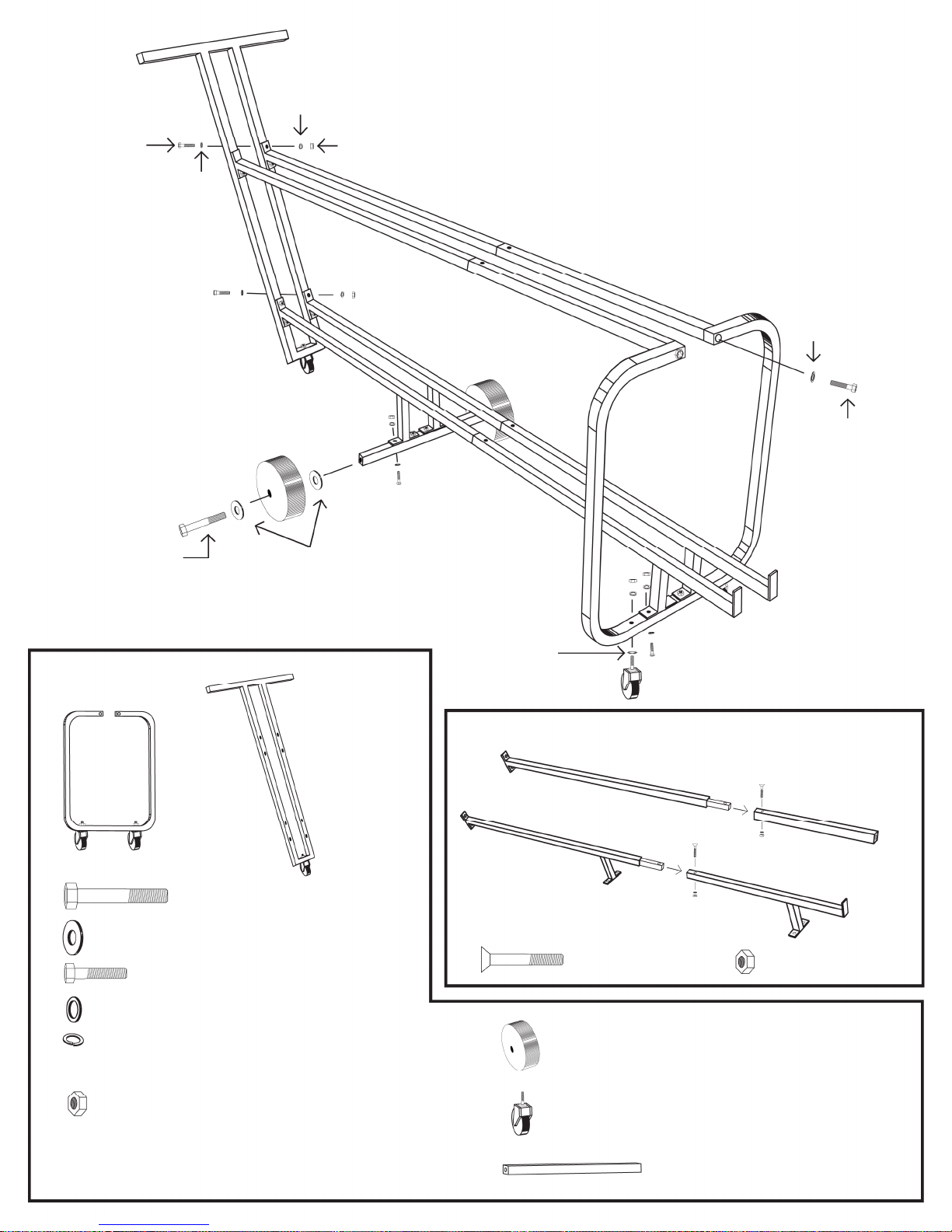
8MM BOLT
SMALL FLAT WASHER
8MM HEX NUT
(16 PLA
CES)
12MM BOLT
LARGE FLAT WASHERS
FRAME
#1921
6” PLASTIC WHEEL (2)
(2 PIECES)
STAR WASHER
Box 1
Box 2
LOCK
WASHER
FLAT
WASHER
8MM BOLT
#1943
END FRAME
Not Pictured
#1935
HANDLE
#1922 12MM AXLE BOLT (2)
#1923 LARGE WHEEL WASHERS (4)
#78 8MM BOLT (18)
#1928 SMALL FLAT WASHERS (16)
#1929 LOCK WASHERS (18)
#1930 8MM HEX NUTS (16)
POLYETHYLENE RAIL COVER (4)
#1939 UPPER BAR
(2 PIECES)
#1941 LOWER BAR
6MM FLAT HEAD
SCREWS (4 PIECES)
#1945 3” THREADED STEM CASTER (3)
With star washer, flat washer & nut
#1937 CENTER AXLE BAR (1)
#1962 UPPER BAR
EXTENSIONS
(2 PIECES)
#1963 LOWER BAR
EXTENSIONS
(2 PIECES)
6MM HEX NUTS
(4 PIECES)
 Loading...