

Page 1

TriggerNG
User Guide
Version 4.5
V4.5
Page 2

V4.5
Page ii
2013 MATE Intelligent Video Ltd All rights reserved.
The copyright and proprietary rights in the guide belong to MATE Intelligent Video Ltd. It is strictly forbidden to copy,
duplicate, sell, lend or otherwise use this guide in any way, shape or form without the prior consent of MATE Intelligent
Video Ltd.
This product is based on software developed by MATE Intelligent Video Ltd.
Redistribution of this manual and its use in binary form (PDF) are permitted, provided that the above copyright notice and
this paragraph are duplicated in all such forms and that any documentation, advertising materials and other materials related
to such distribution and use, acknowledge that the software was developed by MATE Intelligent Video Ltd.
THIS SOFTWARE IS PROVIDED “AS IS” AND WITHOUT ANY EXPRESS OR IMPLIED WARRANTIES,
INCLUDING, WITHOUT LIMITATION, THE IMPLIED WARRANTIES OF MERCHANTABILITY AND FITNESS
FOR A PARTICULAR PURPOSE.
Behavior Watch™, Count Watch™, Cortex™, iSense™, Cortex Server™, Cortex Viewer™ and Rules Manager™ are
trademarks of MATE Intelligent Video Ltd.
All other trademarks used in this document are the property of their respective owners
Page 3

Table of Contents
V4.5
Page iii
TABLE OF CONTENTS
1. Introduction ............................................................................................................... 1-1
1.1. About this Guide .............................................................................................. 1-2
2. Overview ................................................................................................................... 2-1
2.1. The Technology ............................................................................................... 2-2
2.2. Architecture...................................................................................................... 2-2
2.3. Software Architecture ...................................................................................... 2-3
2.3.1. Video Analytics Engine .......................................................................... 2-3
2.3.2. Cortex Server .......................................................................................... 2-3
2.3.3. Cortex Policy Manager ........................................................................... 2-3
2.3.4. Cortex Viewer ........................................................................................ 2-4
2.3.5. Rules Manager/Device Explorer ............................................................ 2-4
3. System Setup ............................................................................................................. 3-1
3.1. In the Package .................................................................................................. 3-1
3.2. Operating System Requirements (Cortex) ....................................................... 3-1
3.3. Installing the Hardware .................................................................................... 3-2
3.4. LED Display .................................................................................................... 3-3
3.5. Installing the Cortex Software ......................................................................... 3-3
3.5.1. Installing .NET Framework .................................................................... 3-3
3.5.2. Cortex Installation .................................................................................. 3-3
3.6. Un-Installing the Software ............................................................................... 3-4
4. Getting Started ........................................................................................................... 4-1
4.1. Initial Use of the Application ........................................................................... 4-1
4.2. StartUp Application ......................................................................................... 4-2
4.2.1. Interface Language ................................................................................. 4-4
5. Rules Manager/Device Explorer ............................................................................... 5-1
5.1. Launching Rules Manager/Device Explorer .................................................... 5-1
5.1.1. Menu Bar ................................................................................................ 5-3
5.2. Device Explorer View...................................................................................... 5-4
Page 4

Table of Contents
V4.5
Page iv
5.2.1. General Settings Tab .............................................................................. 5-4
5.2.2. Video Settings Tab ................................................................................. 5-7
5.2.3. I/O Settings Tab ................................................................................... 5-11
5.2.4. External Interfaces Tab ........................................................................ 5-13
5.2.5. IP Video Source Settings ..................................................................... 5-15
5.2.6. Date Time Settings Tab ....................................................................... 5-16
5.2.7. Additional Settings Tab ....................................................................... 5-16
5.3. Rules Manager View ..................................................................................... 5-17
5.3.1. Tree View ............................................................................................. 5-18
5.3.2. Alarm Geometry Pane .......................................................................... 5-18
5.3.3. Alarm Tab ............................................................................................ 5-19
5.3.4. MSF Schedule Tab ............................................................................... 5-20
5.4. Working with MSFs ...................................................................................... 5-21
5.4.1. Creating an MSF .................................................................................. 5-21
5.4.2. Saving an MSF (BW only) .................................................................. 5-21
5.4.3. Activating/Deactivating a Single MSF ................................................ 5-22
5.4.4. Activating/Deactivating Multiple MSFs .............................................. 5-22
5.4.5. Deleting an MSF .................................................................................. 5-22
5.4.6. Renaming an MSF ............................................................................... 5-22
5.4.7. Copy/Paste an MSF .............................................................................. 5-22
5.4.8. Exporting an MSF ................................................................................ 5-23
5.4.9. Importing an MSF ................................................................................ 5-23
5.5. Working with Alarm Geometries .................................................................. 5-23
5.5.1. ROI Tab for Detection Zone Geometry ............................................... 5-24
5.5.2. Object Sizes Tab .................................................................................. 5-24
5.5.3. Classification Tab ................................................................................ 5-24
5.5.4. Working without Perspective ............................................................... 5-25
5.5.5. Working with Perspective .................................................................... 5-26
5.5.6. Ignore Zone Tab ................................................................................... 5-28
5.6. Setting Alarms ............................................................................................... 5-29
5.6.1. Optional Settings .................................................................................. 5-29
5.6.2. Display and Editing Options ................................................................ 5-29
5.6.3. Scene Switch Feature ........................................................................... 5-30
5.6.4. VMD (Video Motion Detection) Alarm .............................................. 5-33
Page 5

Table of Contents
V4.5
Page v
5.6.5. Static Object Alarm .............................................................................. 5-34
5.6.6. Presence Alarm ..................................................................................... 5-35
5.6.7. Path Detection Alarm ........................................................................... 5-36
5.6.8. Object Started Alarm ............................................................................ 5-37
5.6.9. Directional Motion Alarm .................................................................... 5-38
5.6.10. Loitering Alarm .................................................................................... 5-39
5.6.11. Speed Alarm ......................................................................................... 5-40
5.6.12. Object Removal Alarm ......................................................................... 5-41
5.6.13. Area Coverage Alarm ........................................................................... 5-42
5.6.14. Motion Activity Alarm ......................................................................... 5-43
5.6.15. Creating a Dependency MSF................................................................ 5-44
5.6.16. People Counting ................................................................................... 5-50
5.6.17. Car Counting ........................................................................................ 5-51
6. Access Watch (Tailgating) ...................................................................................... 6-53
6.1. Application Description ................................................................................. 6-53
6.2. Tailgating Detection....................................................................................... 6-53
6.3. Principle of operation ..................................................................................... 6-53
6.4. Architecture.................................................................................................... 6-54
6.5. Camera Installation ........................................................................................ 6-54
6.6. Dependency Rule topology (MSF description) ..................................... 6-556-56
6.6.1. Feed 1 MSF .......................................................................................... 6-57
6.6.2. Feed 2 MSF .......................................................................................... 6-60
7. AVCS ........................................................................................................................ 7-1
7.1. Launching AVCS ............................................................................................. 7-1
7.2. AVCS Interface ................................................................................................ 7-2
7.2.1. Menu Bar ................................................................................................ 7-2
7.3. Cortex Player ................................................................................................... 7-3
8. RTP/RTSP Video Node............................................................................................. 8-1
8.1. RTSP URI Format............................................................................................ 8-2
8.2. General Structure ............................................................................................. 8-2
8.2.1. Mjpeg mode Example............................................................................. 8-3
8.2.2. Multicast Streaming................................................................................ 8-3
8.3. General Video Parameters ............................................................................... 8-4
Page 6

Table of Contents
V4.5
Page vi
8.4. Video Server OSD ........................................................................................... 8-5
8.4.1. Opening a Stream with OSD .................................................................. 8-5
8.4.2. Permanent OSD ..................................................................................... 8-6
9. Factory Defaults ........................................................................................................ 9-1
10. Appendix ................................................................................................................. 10-1
10.1. Trigger NG Hardware Specifications ............................................................ 10-1
10.1.1. Audio Specifications ............................................................................ 10-2
10.2. List of WAN Port Numbers and Applications .............................................. 10-2
11. Index ....................................................................................................................... 11-1
Page 7

Table of Contents
V4.5
Page vii
LIST OF FIGURES
Figure 1: Trigger NG Front Panel ....................................................................................... 2-2
Figure 2: Trigger NG Back Panel ....................................................................................... 2-3
Figure 3: Analog Video Capture Card Question ................................................................ 3-4
Figure 4: Application Settings ............................................................................................ 4-1
Figure 5: StartUp Application ............................................................................................. 4-3
Figure 6: Rules Manager Login .......................................................................................... 5-1
Figure 7: Rules Manager View ........................................................................................... 5-2
Figure 8: Device Explorer View ................................................................................... 5-25-3
Figure 9: Rules Manager/Device Explorer ......................................................................... 5-4
Figure 10: General Settings Tab ......................................................................................... 5-4
Figure 11: Video Settings Tab ............................................................................................ 5-7
Figure 12: Interlaced Image Before Filter ........................................................................ 5-10
Figure 13: De-interlaced Image ........................................................................................ 5-10
Figure 14: I/O Settings Tab - Trigger ............................................................................... 5-11
Figure 15: I/O Settings Tab - iSense ................................................................................. 5-11
Figure 16: External Interfaces tab - Trigger ..................................................................... 5-13
Figure 17: External Interfaces tab - iSense ....................................................................... 5-13
Figure 18: IP Video Source Settings Tab ......................................................................... 5-15
Figure 19: Date Time settings tab ..................................................................................... 5-16
Figure 20: Additional Settings tab ............................................................................ 5-165-17
Figure 21: Rules Manager ................................................................................................. 5-17
Figure 22:Alarm Geometry Pane ..................................................................................... 5-18
Figure 23: Alarm Tab ....................................................................................................... 5-19
Figure 24:MSF Schedule Tab .......................................................................................... 5-20
Figure 25:Alarm Geometries Tabs and the ROI toolbar .................................................. 5-23
Figure 26: Minimum and Maximum indicators ................................................................ 5-26
Figure 27: Perspective ...................................................................................................... 5-27
Figure 28:Object Sizes ..................................................................................................... 5-27
Figure 29:Ignore Zone Tool ............................................................................................. 5-29
Page 8

Table of Contents
V4.5
Page viii
Figure 30:Video Motion Detection Alarm ...................................................................... 5-34
Figure 31:Static Object Alarm ........................................................................................ 5-35
Figure 32:Presence Alarm ............................................................................................... 5-36
Figure 33:Path Detection Alarm...................................................................................... 5-37
Figure 34:Object Started Alarm ...................................................................................... 5-38
Figure 35:Directional Motion Alarm .............................................................................. 5-39
Figure 36:Loitering Alarm .............................................................................................. 5-40
Figure 37:Speed Alarm ................................................................................................... 5-41
Figure 38:Object Removal Alarm ................................................................................... 5-42
Figure 39:Area Coverage Alarm ..................................................................................... 5-43
Figure 40:Motion Activity Alarm ................................................................................... 5-44
Figure 41: Dependency ............................................................................................. 5-455-46
Figure 42:People Counting .............................................................................................. 5-51
Figure 43:Car Counting Top and Side ............................................................................ 5-52
Figure 44:AVCS Interface ................................................................................................ 7-2
Figure 45: Cortex Player .................................................................................................... 7-3
Figure 46: QuickTime Open URL ..................................................................................... 8-1
Figure 47: URL Input Dialog ............................................................................................. 8-1
Page 9

Introduction
V4.5
Page 1-1
1. INTRODUCTION
IN THIS SECTION
About this Guide ............................................... 1-1
Trigger NG™ is a compact, low power, embedded video content analysis and
transmission server for perimeter and site protection. Trigger NG uses DSP
processors to analyze up to 2 video channels concurrently, with video encoding
and transmission over a network.
Current detection features include:
Video Motion Detection for monitoring indoor and outdoor scenes
Path Detection for detecting specific intrusion tactics
Static Object Detection for alerting on stopped vehicles or abandoned
objects
Object Started for detecting when a static object is displaced from its
fixed position
Directional Motion for alerting on movement in a specific direction
Loitering for detecting when a subject remains inside the detection zone
for a specified period of time
Speed for detecting whenever a subject or vehicle violates the designated
speed bounds
Presence Detection for alerting on intrusions into restricted areas
Object Removal for alerting whenever a designated object is fully
removed from the specified region of interest
Area Coverage for alerting whenever coverage of static objects is over or
under a percentage of the region of interest
Motion Activity for alerting whenever coverage of moving objects is over
or under a percentage of the region of interest
Access Watch for alerting when there is tailgating through an access
point: following an authorized and credentialed individual through an
access control point without having or using a separate valid credential.
Page 10

Introduction
V4.5
Page 1-2
1.1. About this Guide
This guide is divided into the following sections:
1. Overview: A general overview of Trigger NG.
2. System Setup: Procedure for setting up the hardware and software.
3. Getting Started: Running the application and a description of the
StartUpApplication.
4. Rules Manager/Device Explorer: Application for the configuration of
Trigger NG.
5. AVCS: Application to store the video clip sequence.
6. Appendix: Hardware and video specifications.
Page 11

Overview
V4.5
Page 2-1
2. OVERVIEW
IN THIS SECTION
The Technology ......................................... 2-22-1
Architecture ...................................................... 2-2
Software Architecture ....................................... 2-3
Trigger NG is based on a proprietary and robust video analytics technology for
object detection, tracking and event identification. Trigger NG is capable of
processing video smartly and independently near the camera, thereby increasing
detection accuracy and fault tolerance while reducing network bandwidth and
overall operation costs. An unlimited number of Trigger NG units can be managed
by the Cortex Video Management System.
The description in this user guide focuses on a single Trigger NG Video Detection
Unit (VDU) and the Cortex software as it pertains to configuring Trigger NG.
Trigger NG is currently available in 5 licensing modes:
Trigger NG: analyzes up to 2 video channels concurrently, up to 5 rules per
channel, and supplies an analog output with an overlay of analytic alerts. The
analog output can display the 2 channels side by side or switch between the
channels upon event.
Trigger NG 2S: analyzes up to 2 video channels concurrently, up to 2 rules
per channel, with streaming at 4CIF quality at 7 fps, or CIF quality at fullframe rate.
Trigger NG 1S: analyzes 1 video channel, up to 2 rules, with streaming at
4CIF quality at full-frame rate.
Trigger NG 1A: analyzes 1 video channel, up to 2 rules, with streaming at
4CIF quality at minimal frame rate (2 fps) and supplies an analog output with
an overlay of analytic alerts.
Trigger NG 2A: analyzes 2 video channels, up to 2 rules per channel, with
streaming at 4CIF quality at minimal frame rate (2 fps) and supplies an analog
output with an overlay of analytic alerts. The analog output can display the 2
channels side by side or switch between the channels upon event.
NOTE:
All Trigger NGs support both analog and IP video inputs. Each input can be
configured to capture an analog input or an IP video stream.
All Trigger NGs support Motion JPEG or MPEG4 compression format and the
RTP/RTSP network protocol.
Page 12
Overview
V4.5
Page 2-2
2.1. The Technology
Behavior Tracking is a domain of Video Content Analysis (VCA) that applies
specific rules to detect and alert numerous violations and irregular conduct:
abandoned objects, stopped cars, perimeter breach, etc. The field of VCA is also
known as Computer Vision.
2.2. Architecture
The video detection and management system built with one or more Trigger NG
units is comprised of different modules, each fulfilling a specific task. The system
is scalable from a single Trigger NG processing two video feeds, to a large
network analyzing a large number of video cameras. The architecture remains the
same, although the component parts may end up residing on different computer
platforms.
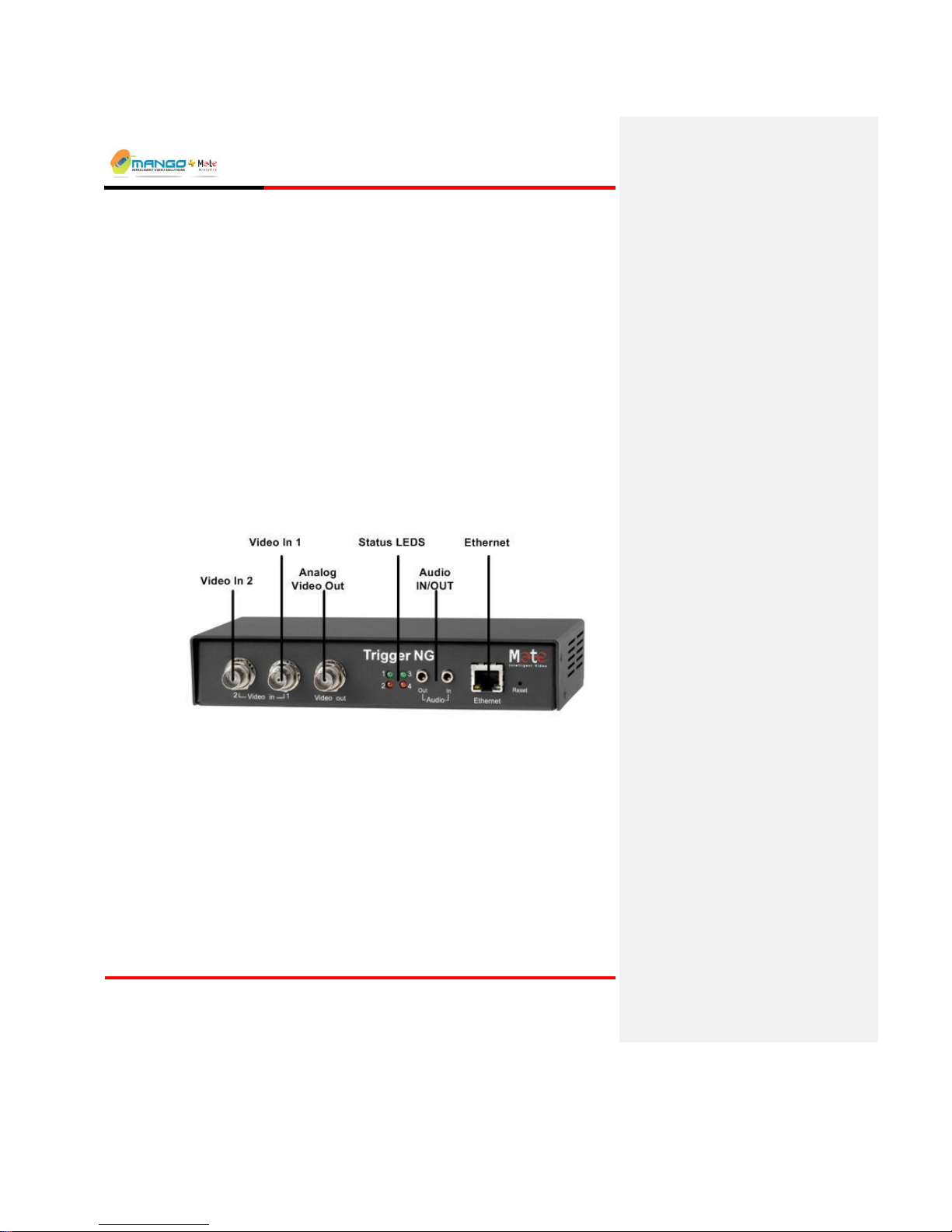
FIGURE 1: TRIGGER NG FRONT PANEL
Page 13
Overview
V4.5
Page 2-3
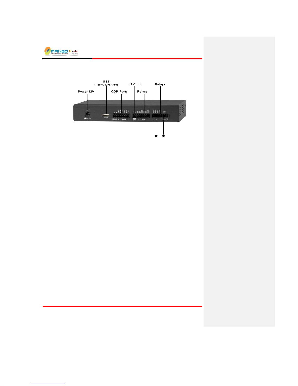
Input
Relays
Counter
Relays
FIGURE 2: TRIGGER NG BACK PANEL
2.3. Software Architecture
The system consists of the following modules:
2.3.1. Video Analytics Engine
The Trigger capturing and analyzing unit captures the analog video from the
camera. Its embedded video analytic engine loads rule-sets known as MSFs that
define the video-based alarm criteria per camera. Video frames are received from
the analog video and then analyzed to detect events that match the loaded rulesets.
2.3.2. Cortex Server
Cortex Server serves as the communications and control backbone of the
application. This program automatically minimizes to the system tray on startup
and runs in the background.
2.3.3. Cortex Policy Manager
The Cortex Policy Manager is a tool for configuring the system authorization
levels. For each of the authorization levels, there are strict permitted actions. The
tool enables an authorized person (such as an administrator) to add and delete
system users as well as to designate or modify a specific level of authorization for
each user. The Cortex Policy Manager displays a hierarchy of sites, connected
devices to each site, and the number of video feeds on each device. An
administrator can grant individual or grouped users with viewing and/or setting up
permissions for selected sites, devices and individual video feeds. This serves as a
Page 14

Overview
V4.5
Page 2-4
security mechanism to limit the user’s scope in accessing and operating the
system.
2.3.4. Cortex Viewer
Cortex Viewer serves as the main user interface for viewing the status of the
device and each of its connected cameras, and for displaying live video images
with video tracking overlay.
*The installation includes one Cortex Viewer installed on the same machine for
local operation. The Cortex Viewer is pre-configured to operate with the local
Cortex Server installed on the same machine (local IP Address 127.0.0.1).
2.3.5. Rules Manager/Device Explorer
The Rules Manager program defines and manages rule-sets that specify the type,
shape, location and other key-parameters of detectable events. Once defined, the
rules are uploaded to reside on the device and configure the operation of the
Video Analytics Engine.
Device Explorer is used to set up the network configuration and advanced settings
of the VDU.
Page 15

System Setup
V4.5
Page 3-1
3. SYSTEM SETUP
IN THIS SECTION
In the Package ............................................................... 3-1
Hardware and Operating System Requirements ........... 3-1
Installing the Hardware .................................................. 3-2
LED Display ................................................................... 3-3
Installing the Cortex Software ........................................ 3-3
Un-Installing the Software .............................................. 3-4
The Trigger NG device comes pre-installed with its own embedded software. The
Installation CD with the Cortex software is provided for controlling and managing
the Trigger NG.
3.1. In the Package
The Trigger NG product package includes:
Trigger NG device with power supply (auto-select 110V/220V).
Installation CD .
3 connectors (8-pin).
The following components are NOT supplied:
Video Cameras.
Video, Ethernet and Electric cables.
External output device/application (optional).
3.2. Operating System Requirements (Cortex)
Software:
Microsoft Windows Server 2003 Standard Edition SP2 (32-bit)
NET Framework 2.0 or higher (provided on the installation CD)
Internet Information Services (IIS Windows Component)
Page 16

System Setup
V4.5
Page 3-2
INFORMATION:
To add the IIS Windows component: Start Settings Control Panel
Add or Remove Programs Add/Remove Windows Components (may
require the Microsoft Windows XP setup disk if not already installed).
NOTE:
Regional and Language option should be set to English (United States).
3.3. Installing the Hardware
Physically connect the Trigger NG to the network using a network cable. The
Ethernet port is located on the front panel of the Trigger NG.
Physically connect up to two video cameras to the Video In sockets located on the
front panel of the Trigger NG. Use BNC connectors.
If you are using the analog video output, connect it your analog monitor.
Connect the power supply to the socket located on the back panel of the Trigger
NG. Make sure the Power Supply itself is located close to the Trigger NG.
NOTE:
See the Appendix (on Page 10-19-1) for the technical specifications of all
connections.
Page 17
System Setup
V4.5
Page 3-3
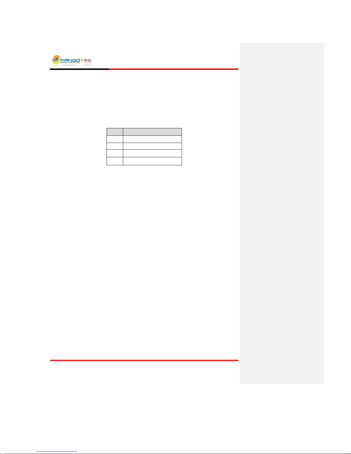
3.4. LED Display
Once the power is connected, the LED Panel displays the following information:
Trigger NG LED Display
LED
Description
1
Video Input 1 Active
2
Video Input 2 Active
3
N/A
4
Connection to Cortex
3.5. Installing the Cortex Software
Use the Cortex software to control and manage the Trigger NG.
3.5.1. Installing .NET Framework
The .NET Framework is a component of the Microsoft Windows® operating
system used to build and run Windows-based applications. The software requires
.NET Framework 2.0 to run properly. Part of the installation of the bundled
software checks if .NET Framework 2.0 already exists on the computer and offers
to install the software if it cannot find it. The software will not work without the
.NET Framework.
3.5.2. Cortex Installation
1. Insert the Cortex Installation CD and run the Setup application located in the
root directory on the CD.
2. Read the Software License Agreement and select Yes to continue.
3. Choose a setup type from the available options:
Complete to install the basic support for files and Direct Show (Analog video
capture device) as well as support for Intellex, Axis and Sony.
Custom to selectively decide which support to add in addition to the basic
support for files and Direct Show.
Click Next to continue.
4. At the Event Media Setup Wizard Click Next to continue.
5. Either accept the default location for the installation of the program files, or
browse to another location, and then click Next to continue.
Page 18
System Setup
V4.5
Page 3-4
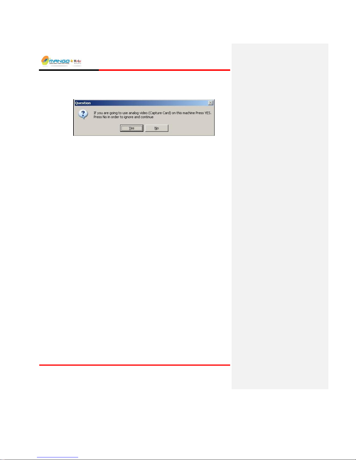
6. Wait until all the files and device drivers are installed (follow on screen
instructions). Click Yes At the pop up window question if you are going to
use analog video, or No in order to ignore and continue.
FIGURE 3: ANALOG VIDEO CAPTURE CARD QUESTION
7. Wait until all the files and applications are installed, clicking Next when
prompted with each sub-installation. Click Finish to restart your computer,
and once Windows reloads, complete the Ajax sub-installation by clicking
Next when prompted.
Shortcuts to VCA and VCA Utilities are placed on the desktop.
IMPORTANT:
Restarting the computer is vital to the installation process. Running the
application before restarting your computer may cause some components of the
application not to function properly.
3.6. Un-Installing the Software
To uninstall the Cortex software:
1. Click Start Settings Control Panel Add or Remove Programs
find Cortex in the list and select it click the Change/Remove button.
2. In the Installation Wizard that opens, choose Remove to uninstall all the
software.
Page 19
Getting Started
V4.5
Page 4-1
4. GETTING STARTED
IN THIS SECTION
Initial Use of the Application ............................. 4-1
StartUp Application .......................................... 4-2
NOTE:
Verify that the Windows Firewall software is NOT operational: Cortex does not
support the operation of any firewall software.
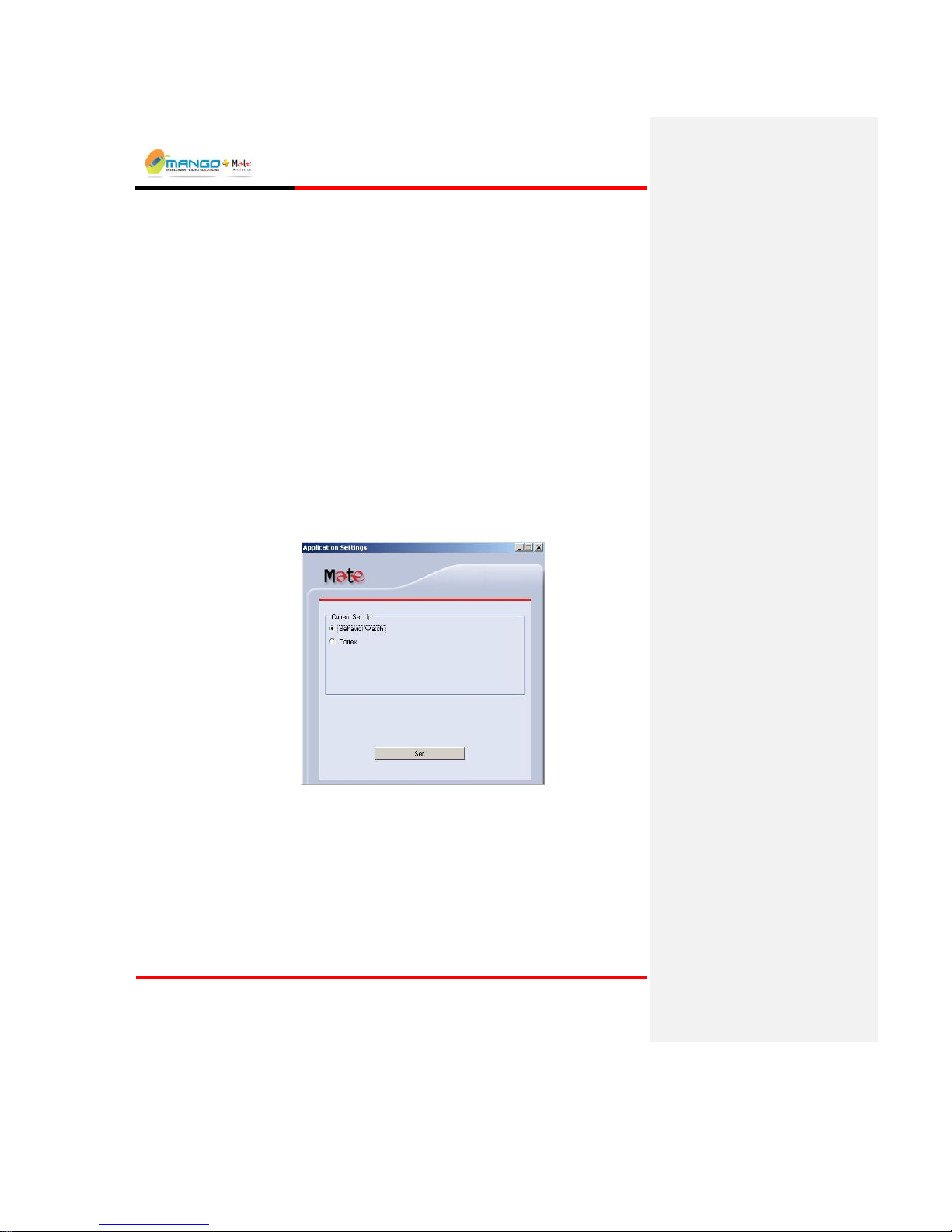
4.1. Initial Use of the Application
When running the application for the first time after installation, an Application
Settings window is opened. Click the applications that you are licensed to use. If
you are running Cortex select Cortex.
FIGURE 4: APPLICATION SETTINGS
After the installation finishes (and after restarting the computer), double-click on
the VCA shortcut placed on the desktop during installation. The StartUp
Application launches and minimizes to the system tray. The StartUp Application
also automatically opens the Cortex Server and Cortex Viewer programs.
In addition, pop-up boxes will request certain information in order to correctly
configure the application:
Page 20

Getting Started
V4.5
Page 4-2
Device ID: Every device in the Cortex network needs a unique identifier. Enter a
number that will be unique to the installed computer and click OK (make up a
number): any integer between 1 and 9999 can be entered in this field, as long as
each device and Cortex in the same network has a different number.
Cortex Server IP: Enter the IP Address of the Cortex Server and click OK. This
is the IP address of the installed (local) computer.
WAN IP Address: In case the Cortex Viewer and the VDU are not residing
within the same LAN (since the Cortex Viewer can be installed on multiple
computers using the Cortex Viewer Installation CD), the VDU needs to know the
preconfigured WAN IP Address of the Cortex Viewer, as the VDU sends video
directly to the Cortex Viewer, bypassing the Cortex Server application. Enter the
IP Address and click OK. If running no other instance of Cortex Viewer outside
the same LAN, click Cancel.
4.2. StartUp Application
The StartUp Application is an all-in-one application that performs the following
actions:
Launches all critical software programs running on the Cortex computer
platform (such as Cortex Server and Cortex Viewer).
Configures the Interface language.
Monitors all critical programs status.
Page 21
Getting Started
V4.5
Page 4-3
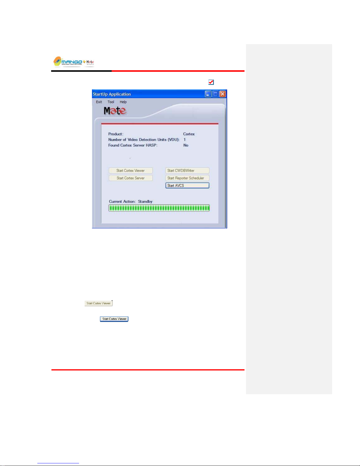
Access the StartUp Application by clicking the system tray icon: .
FIGURE 5: STARTUP APPLICATION
The following is a description of the StartUp Application dialog screen:
Product – The product's name.
Number of Video detection Units (VDU) – the maximum number of Video
Detection Units the application is licensed to control.
Current Action – shows the launching progress; displays "Standby" when
launching completes.
In addition, there are buttons for each sub application:
A disabled and pressed button indicates the application is already running:
.
An enabled button indicates the application can be launched by pressing the
button:
NOTE:
If any of the buttons are not visible, open the Configuration Window (Tools
Configuration) and select the applications to run. Restart the StartUp Application
for the change to take effect.
Page 22

Getting Started
V4.5
Page 4-4
4.2.1. Interface Language
StartUp Application can be optionally configured to display the user interface in
another language:
1. To change the interface language:
Click Tool Interface Language and select one of the languages available.
2. The language change affects the following applications: StartUp Application,
Cortex Viewer, Cortex Searcher, Cortex Player, Reporter Manager, Rules
Manager and Policy Manager (where applicable).
NOTE:
You must restart the StartUp Application for the changes to take effect.
Page 23
Rules Manager/Device Explorer
V4.5
Page 5-1
5. RULES MANAGER/DEVICE EXPLORER
IN THIS SECTION
Launching Rules Manager/Device Explorer ..... 5-1
Device Explorer View ....................................... 5-4
Rules Manager View ......................................5-17
Working with MSFs ........................................5-21
Working with Alarm Geometries.....................5-23
Setting Alarms ................................................5-29
Alarm Types ........................................... 5-325-33
The Rules Manager program selects, configures and manages video detection
rule-sets. Device Explorer is the application used to remotely configure Video
Detection Units on the network. Although Video Detection Units come preset
with default settings, it is important to change these settings to suit the specific
network.
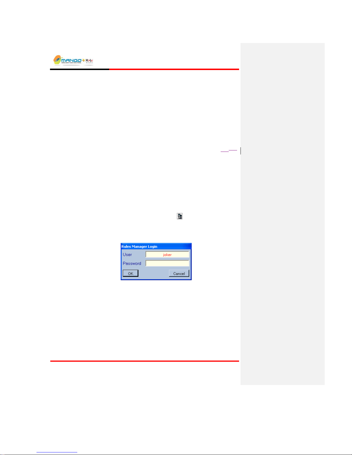
5.1. Launching Rules Manager/Device Explorer
1. Double-click the desktop Rules Manager icon. The Rules Manager Login
window opens.
2. The Rules Manager Login window opens. Type joker in the User field.
Leave the password blank, and then click OK.
FIGURE 6: RULES MANAGER LOGIN
3. The Rules manager window opens.
4. From the Tools tab select Device Explorer to switch between the Rules
manager View and Device Explorer view.
Page 24
Rules Manager/Device Explorer
V4.5
Page 5-2
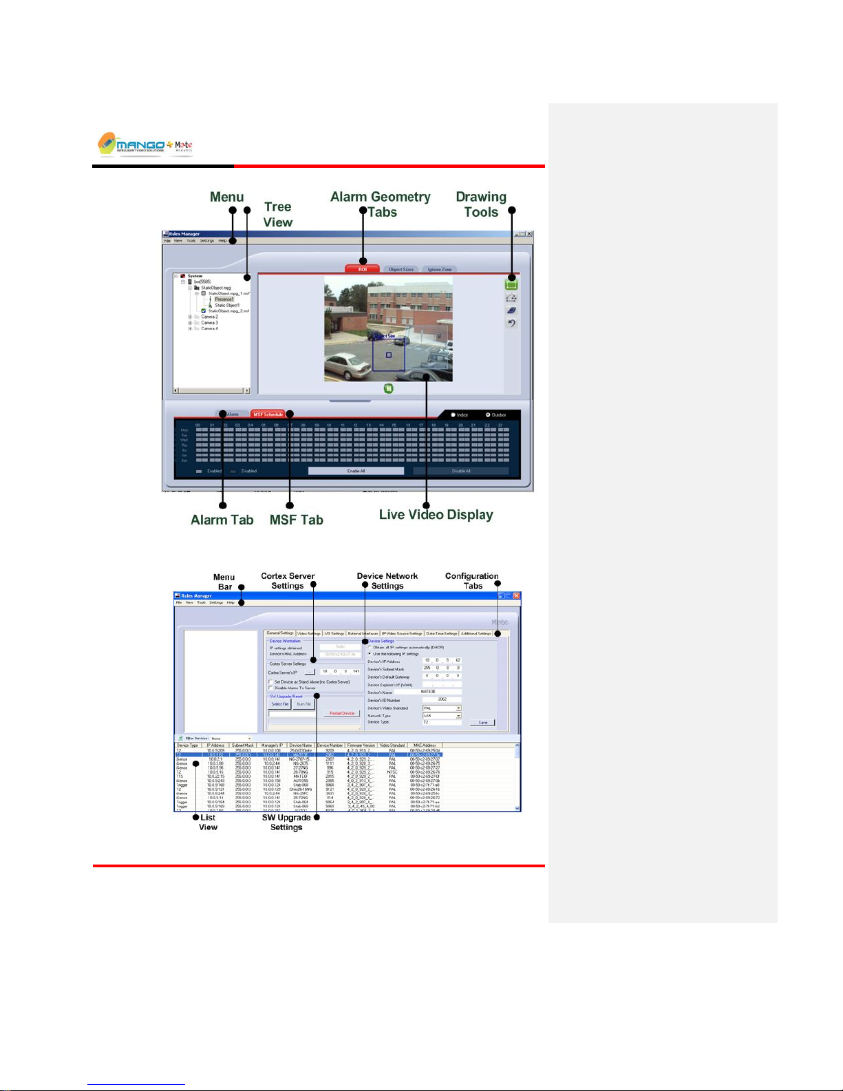
FIGURE 7: RULES MANAGER VIEW
FIGURE 8: DEVICE EXPLORER VIEW
Page 25

Rules Manager/Device Explorer
V4.5
Page 5-3
5.1.1. Menu Bar
Consists of shortcuts to various functions:
File:
Exit the application
View: Switch between video setting and mapping setting
Video – Displays live video
Mapping – Display map with camera icon location
Tools:
Connect to Device in Default Cortex Server – Connects to Cortex
Server
Device Explorer - click to switch from Rules Manager view to Device
Explorer view
Settings:
Change Credential Account – change user password
Change Interface Language – Select language
Help:
About - Opens the About Us dialog
Rule Manager Help - Opens the online help
Page 26
Rules Manager/Device Explorer
V4.5
Page 5-4
5.2. Device Explorer View
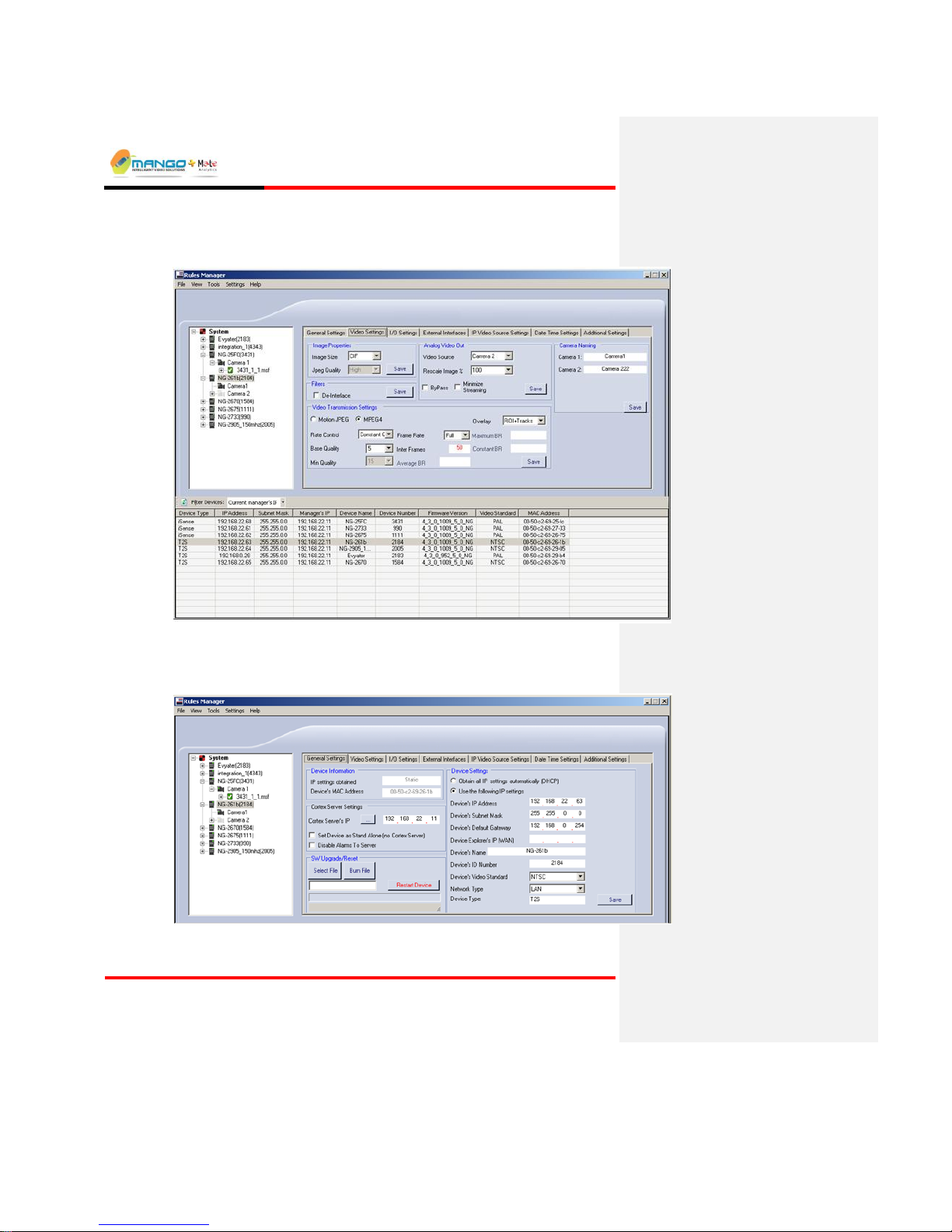
FIGURE 9: RULES MANAGER/DEVICE EXPLORER
5.2.1. General Settings Tab
FIGURE 10: GENERAL SETTINGS TAB
Page 27

Rules Manager/Device Explorer
V4.5
Page 5-5
5.2.1.1. Device Information
Displays the IP Settings obtained and the current MAC Address of a device
selected in the List View. All fields are read-only and cannot be edited.
5.2.1.2. Device Settings
Displays the current configuration settings of a device selected in the List View.
Edit the fields as follows:
Select either to Obtain all IP settings automatically (DHCP) or to Use the
following IP settings:
Device’s IP Address: A unique IP Address conforming to the subnet of
the network where the device is installed.
Device’s Subnet Mask: The subnet mask of the network.
Device’s Default Gateway: The IP Address of the network gateway (can
be left blank for devices installed within the network).
Device Explorer's IP (WAN): In order to update parameters and firmware
with Device Explorer over a Wide Area Network (WAN), enter a WAN
IP or NAT Address (port 1984) in this field.
Device’s Name: A user-defined name making it easier to identify the
device.
Device ID Number: Every device in the Cortex network has a unique
identifier. Enter a number that will be unique to this device (make up a
number): any integer between 1 and 9999 can be entered in this field, as
long as each device in the same Cortex network has a different number.
Device’s Video Standard: PAL or NTSC.
Network Type: Optimize the device to work within a Local Area
Network (LAN) or a Wide Area Network (WAN).
Device Type: Displays the device type.
Edit the fields as desired and then click Save to apply the new settings, and
wait for the message box indicating configuration was successful.
NOTE:
If connecting more than one device to the same Cortex Server, make sure that all
the devices use the same video standard (PAL or NTSC).
5.2.1.3. Cortex Server Settings
Enter the Cortex server IP Address. If there is no Cortex Server select the
checkbox Set Device as Standalone.
Cortex Server’s IP Address: The IP Address of the Cortex Server. This same
IP Address was configured for the Cortex computer when connecting it to the
local network and assigning an IP Address. This same IP Address is filled in
this same field for all the Video Detection Units managed by Cortex in the
network.
Page 28

Rules Manager/Device Explorer
V4.5
Page 5-6
Click the ellipse button to fill the field with the Local Machines IP
Address: .
Disable Alarms to Server: Select this checkbox to disable alarms sent to
server.
5.2.1.4. S/W Upgrade/Reset
The Device Explorer can be used to update the device’s software or upgrade the
license, via the Select File button. Follow this procedure only after receiving a
certified update from technical support. Updates are available as .BIN files that
should be stored on the PC.
To upgrade the software:
1. Unplug all video cables from the device.
2. Restart the device by clicking on Restart Device button in Device Explorer
application. Wait for Trigger unit to return to device tree.
3. Select the device in the List View of Device Explorer and then click the
Select File button to browse for the file in its saved location. Click OK to
confirm. Once the Bin file is selected, click the Burn File button and wait for
approximately one minute for the process to complete. Click OK to co nfirm.
4. Plug in the video cables.
This process needs to be repeated for each device to be updated.
To upgrade the license:
1. Unplug all video cables from the device.
2. Restart the device by clicking on Restart Device button in Device Explorer
application.
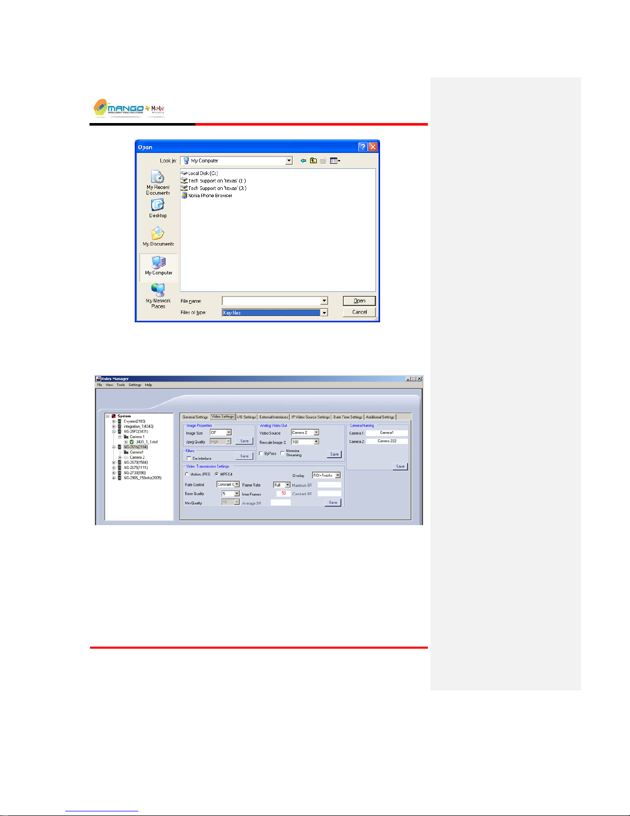
3. Select the device in the List View of Device Explorer and then click the
Select File button to browse for the Key file in its saved location. From the
Files of Type drop down list (shown below) select Key files. Once the Key
file is selected, click the Burn File button and wait for approximately one
minute for the process to complete.
Page 29
Rules Manager/Device Explorer
V4.5
Page 5-7
4. Plug in the video cables.
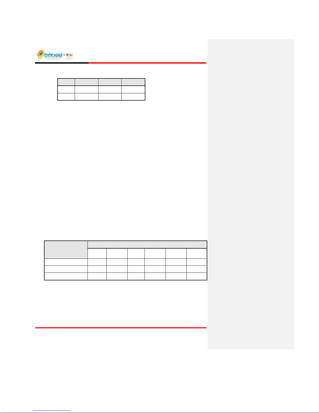
5.2.2. Video Settings Tab
FIGURE 11: VIDEO SETTINGS TAB
5.2.2.1. Image Properties
The Image Properties are effective in controlling bandwidth by allowing for the
customization of the resolution of the transmitted images as follows:
Image Size: Choose between 4CIF, CIF or QCIF.
Page 30
Rules Manager/Device Explorer
V4.5
Page 5-8
4CIF
CIF
QCIF
NTSC:
704 x 480
352 x 240
176 x 120
PAL:
704 x 576
352 x 288
176 x 144
Jpeg Quality: Choose between:
High: default value and recommended for all LANs.
Medium: recommended for WANs with more than 1Mb bandwidth.
Low: recommended for WANs with less than 1Mb bandwidth.
Click the Save button to apply any new settings.
5.2.2.2. Video Transmission Settings
The Video Transmission Settings allow for customization of the format of the
transmitted video images.
When selecting MPEG4 mode, select the Rate Control as follows:
Constant Quality: No Rate Control mechanism is used. The quality of the
compressed video output is fixed by the means of using a constant parameter
for the quantization factor, which is determined by the Base Quality parameter.
This is the only Rate Control related value that is taken into account.
VBR (Variable Bit Rate): A bit stream of variable bit rate is generated by the
VDU. The parameters to be used in this case to adjust the performance and
behavior of the VDU are: Base Quality, Average BR and Maximum BR.
CBR (Constant Bit Rate): A bit stream of constant bit rate is generated by the
VDU. The parameters to be used in this case to adjust the performance and
behavior of the VDU are: Base Quality, Min Quality and Constant BR.
Configure the Rate Control parameters as follows:
RATE
CONTROL
PARAMETERS TO SET:
BASE
QUALITY
MIN
QUALITY
INTER
FRAMES
AVERAGE
BR
MAXIMUM
BR
CONSTANT
BR
Constant Quality
VBR (Variable Bit Rate)
CBR (Constant Bit Rate)
Base Quality designates the desired quality of sent frames (the lower the number,
the higher the quality). This is the recommended setting.
Min Quality designates the minimum allowed quality of sent frames (the lower
the number, the higher the quality).
Frame Rate determines how the frames are sent (Full sends all frames, Half
sends every second frame, and 1/3 sends every third frame).
Page 31

Rules Manager/Device Explorer
V4.5
Page 5-9
Inter Frames determines when a full frame is sent and not just a delta (e.g., 15
would mean every 15th frame is a full frame).
Average BR designates the desired bit rate (between 50000 and 1500000 for CIF,
and between 50000 and 3000000 for 4CIF).
Maximum BR designates the maximum allowed bit rate (between 50000 and
between 1500000 for CIF, and 50000 and 3000000 for 4CIF).
Constant BR designates the allowed bit rate (between 50000 and 1500000 for
CIF, and between 50000 and 3000000 for 4CIF).
NOTE:
For most situations using MPEG4 mode, a Rate Control of Constant Quality is
recommended (setting Base Quality to 7 and Inter Frames to 25).
Use the Overlay field to decide between sending video together with:
ROI and Tracks (Region of Interest and motion tracking),
ROI only,
Tracks only, or
None (i.e., only video).
Click the Save button to apply any new settings.
5.2.2.3. Analog Video Out
The Video Source setting activates the Video Out port (select None to disable
Video Out).
When selecting the analog video output, select the video source as follows:
Camera: Choose Camera1 or Camera2 as the video source. The analog video
output is fixed to the camera and appears as a full screen.
Alarmed Camera: The camera that gets an alarm will appear on the analog
video output for at least 5 seconds before switching to the next camera if
needed.
Both: The analog video output displays both cameras on the same display in
smaller size.
You can rescale the image by selecting a percentage from the Rescale Image %
drop down list.
Check the ByPass box to send video only to the Video Out port (without ROI
and Tracking), for example, when the video has lots of objects drawn on the
video that may interfere with a clear view of the scene.
Check the Minimize Streaming box to dramatically lower the frame rate sent
over the network (just enough to enable use of Rules Manager).
Click the Save button to apply the new settings.
Page 32

Rules Manager/Device Explorer
V4.5
Page 5-10
5.2.2.4. Camera Naming
Displays the current camera names on the selected device. Change the names as
desired and click the Save button to apply the new settings.
NOTE:
In T1 and iSense there will be only one camera available.
5.2.2.5. De-Interlace Filter
De-Interlace helps prevent visual defects called interlace artifacts or combing
which occur with moving objects in the image. When there is a lot of motion in a
scene the image may be blurred and objects can be duplicated. In order to tell if a
camera is interlacing is to rapidly move the camera and see whether objects are
duplicated or not. The figure below demonstrates this phenomenon.
FIGURE 12: INTERLACED IMAGE BEFORE FILTER
If this occurs check the De-Interlace Filter box. The image after the filter is
applied is shown below.
Click the Save button to apply the new setting.
FIGURE 13: DE-INTERLACED IMAGE
Page 33

Rules Manager/Device Explorer
V4.5
Page 5-11
5.2.3. I/O Settings Tab
The I/O settings tab for Trigger and ISense are shown below:
FIGURE 14: I/O SETTINGS TAB - TRIGGER
FIGURE 15: I/O SETTINGS TAB - ISENSE
5.2.3.1. Relay / Input
The Relay / Input settings relate to how the device handles the activation of relays
and inputs.
Relay Policy - Determines how the output relay is activated (when an alarm is
triggered on any video feed), as follows:
Idle - No activation of the output relay on an alarm (must be set to Idle in
order to allow manual activation of relays through the Cortex Viewer).
Pulse - Activation of the output relay for an amount of time (from 1 - 300
seconds) set by Pulse Duration (sec).
Level - Activation of the output relay for an amount of time corresponding to
the duration of the alarm.
Page 34

Rules Manager/Device Explorer
V4.5
Page 5-12
Alarms H/W Switch (Trigger) – Determines whether a hardware switch (closing
the input contacts) assigned to a video feed has any effect on alarms generated, as
follows:
Checked - Closing an input contact assigned to a video feed effectively
means that no alarms are generated on that feed (no video analytics).
Unchecked - The status of the input contact (H/W Switch) is ignored.
Alert Video Loss (Trigger only) – Determines whether an alarm is triggered
when video is lost on a video feed (disabled if Relay Policy is set to Idle).
Counting H/W Switch (iSense) – Determines whether a hardware switch
(closing the input contacts) assigned to a video feed has any effect on counting
alarms generated, as follows:
Dry Contact Pulse Duration (milliseconds) – Set the sampling rate of the relay
input (used in the dependency rule).
Click the Save button to apply any new settings.
5.2.3.2. Audio Devices
Display the current configuration status of the audio ports on the selected device.
Enable/disable the ports as required and click the Save button to apply the new
settings.
5.2.3.3. LED Status
Enable or Disable the LED state.
5.2.3.4. Database Update Interval (for iSense only)
Determine the Database Update Interval in seconds.
Page 35

Rules Manager/Device Explorer
V4.5
Page 5-13
5.2.4. External Interfaces Tab
The External Interfaces tab for Trigger and ISense are shown below:
FIGURE 16: EXTERNAL INTERFACES TAB - TRIGGER
FIGURE 17: EXTERNAL INTERFACES TAB - ISENSE
5.2.4.1. AVC Server – Trigger Only
The Video Detection Unit (e.g. Trigger NG) can be configured (optionally) to
send a video clip of an event to a specific IP Address where an AVC Server
resides. The AVCS stores the information for browsing and presentation via the
Cortex Player.
NOTE:
The AVC Server works only in the T2 NG mode and not in the 2S, 1S, 2A or 1A
modes.
AVCS must be installed on the AVCS Server.
Page 36

Rules Manager/Device Explorer
V4.5
Page 5-14
To configure the embedded parameters on a VDU, edit the fields as follows:
IP Address: The IP Address of the AVC Server.
Port Number: The port number of the AVC Server (preset to 1976).
Frame Rate: Offers a means to reduce the quality of a video clip, in order to
ensure that the video clip can still be transmitted without error over a limited
bandwidth network.
High: all video frames are sent over the network (default value and recommended for
all LANs).
Medium: every second video frame is sent over the network (recommended for WANs
with more than 1Mb bandwidth).
Low: every third video frame is sent over the network (recommended for WANs with
less than 1Mb bandwidth).
Disable: A check in this box stops storing video on the AVC Server.
Click the Save button to apply any new settings.
5.2.4.2. Interface Definition
Select the interface type. Select either the Default or the Milestone interface type.
5.2.4.2.1. Metadata Channel Configuration
A Metadata application running on the device can be configured (optionally) to
send metadata to a specific IP address where another Metadata application (acting
as a client or server) resides, receiving messages from the VDU using XML over
TCP/IP. The server application is responsible for connection handling and
monitoring. The Multi Metadata channel configuration allows you to configure
and enable multiple metadata IP Addresses
To configure the device's embedded parameters that are needed to send
information to multiple Metadata applications, edit the fields as follows:
Enabled: A check in this box enables sending updates to the Metadata
applications.
IP Address: The IP Address of the Metadata applications.
Port Number: The port number of the Metadata applications.
For Trigger set to 1979.
For iSense set to 1977.
Device Will Act As a: Select whether the device will act as a Server or Client
(if the other application is set as the Server).
Enable Receiving Metadata: A check in this box enables receiving updates
from the Metadata application (for dependency use).
Page 37

Rules Manager/Device Explorer
V4.5
Page 5-15
Receiving Port Number: The port number to receive the Metadata from.
Click the Save button to apply any new settings (for dependency use).
5.2.4.2.2. DVR
If using a DVR in conjunction with the VDU, configure the DVR settings as
follows:
DVR Type: Select the type of DVR to receive alarm notifications from the
list
DVR's IP: The IP Address of the DVR
First Camera: The camera (feed) number of the first DVR feed. If more than
1 feed is used they must all be in consecutive order relative to the first feed
(e.g. 2 and 3, or 6 and 7)
Alarms (Trigger only): Checking this box will send alarms to the DVR
Alarms Port (Trigger only): Port Address for sending alarms to the DVR (It
is recommended to keep the default value)
Click the Save button to apply any new settings.
5.2.5. IP Video Source Settings
FIGURE 18: IP VIDEO SOURCE SETTINGS TAB
The IP Video Source Settings allows you to choose an IP camera source as an
input to the device. Consult with a local service representative for information on
supported cameras and URL syntax.
Input the URL of the IP camera source
Select the checkbox Use Video Over IP
From the Feed drop down list select the number of the video feed
Click Save. For further details refer to an authorized sales representative.
Set the RTCP Synchronization timeout interval in seconds.
Page 38

Rules Manager/Device Explorer
V4.5
Page 5-16
5.2.6. Date Time Settings Tab
FIGURE 19: DATE TIME SETTINGS TAB
The Date and Time Settings tab is used for an external NTP server to synchronize
all devices to an external time generator.
Select the checkbox to use the NTP Server
Enter the Time Zone (difference in minutes from UTC)
Enter the update frequency in minutes
Enter the IP Address of the NTP Server
Click Save to apply the settings.
5.2.7. Additional Settings Tab
FIGURE 20: ADDITIONAL SETTINGS TAB
Page 39

Rules Manager/Device Explorer
V4.5
Page 5-17
5.2.7.1. Video Server
When the maximum streams are utilized, the server should provide a stream with
matching Encoding, Resolution, or Bit Rate. Otherwise request will be rejected.
Select the checkbox Encoding, Resolution, or Bit Rate.
Select the checkbox to enable RTCP. Click Save.
5.3. Rules Manager View
FIGURE 21: RULES MANAGER
Tree View: displays a hierarchy of connected Video Detection Units (VDUs),
video feeds and rule-sets, known as MSFs, for easy access to these elements.
Alarm Geometry: comprises Live Video Display, Alarm Geometry Tabs
(e.g. ROI, Object Size, Ignore Zone) and a tab-sensitive Drawing Toolbar to
support drawing of alarm zones, object sizes and optional ignore zones on the
video window.
Alarm and MSF Schedule Tabs: located at the bottom of the Rules Manager
display, for setting alarm-specific and MSF-specific attributes,
correspondingly.
Page 40

Rules Manager/Device Explorer
V4.5
Page 5-18
5.3.1. Tree View
The Tree View pane on the left side displays a list of connected devices, and for
each device, a hierarchy of video feeds per device, MSF per video feed, and
detection zones (ROI) set for each MSF.
The Tree View shows all the units connected to the same Cortex server.
To connect to a VDU device that is defined as a standalone device:
In the Device Explorer view double click on the device.
The device Tree View with its cameras will open in the Rules Manager view.
5.3.2. Alarm Geometry Pane
FIGURE 22:ALARM GEOMETRY PANE
The Alarm Geometry pane comprises the following parts:
Live Video - shows the selected video feed. A Play/Pause button is located
under the video frame. When pressed, the button pauses the video in the Rules
Manager to capture a subject and use its image to facilitate setup.
Alarm Geometry Tabs – located on top of the video display (displayed
when an alarm is highlighted).
Drawing Toolbar – located to the right of the video display and displayed
when an alarm is highlighted. The toolbar's content varies according to the
Alarm Geometry Tab that is highlighted.
Page 41

Rules Manager/Device Explorer
V4.5
Page 5-19
5.3.3. Alarm Tab
The Alarm tab may include a means to set the sensitivity for specific alarm
notifications. With some alarm types, the tab also displays additional setting
options (discussed under the relevant alarm type sections).
FIGURE 23: ALARM TAB
5.3.3.1. Sensitivity
The performance of video detection systems is usually measured by the
probability of detection for the desired event / behavior, and by the false alarm
rate. The default sensitivity is tuned to balance these two performance measures.
The sensitivity slider can be used in certain scenarios for better control of these
values. Starting with medium sensitivity (the default), you may select Low
sensitivity for further reduction in false alarm rate with somewhat reduced
probability of detection. Alternatively, you may increase sensitivity to High for
detecting small or low-contrast objects, at the expense of a slightly higher false
alarm rate.
5.3.3.2. Activate Relay
Activate Relay only appears as an option for alarms set for Trigger NG devices.
Activating this checkbox for the specified alarm will also activate the alarm relay
on the device. The alarm relay on the device can be physically connected to an
external alarm that will also sound when the alarm is triggered.
NOTE:
This feature is only functional if the Relay Handling policy has been activated for
the device through the Device Explorer application.
5.3.3.3. Enable Relay Output for System Event
Enable Relay Output for System Event only appears as an option for PC-based
VDUs (e.g., Behavior Watch). Activating this option for the specified alarm will
also activate the optional alarm relay connected to the USB port of the PC-based
VDU.
Page 42
Rules Manager/Device Explorer
V4.5
Page 5-20
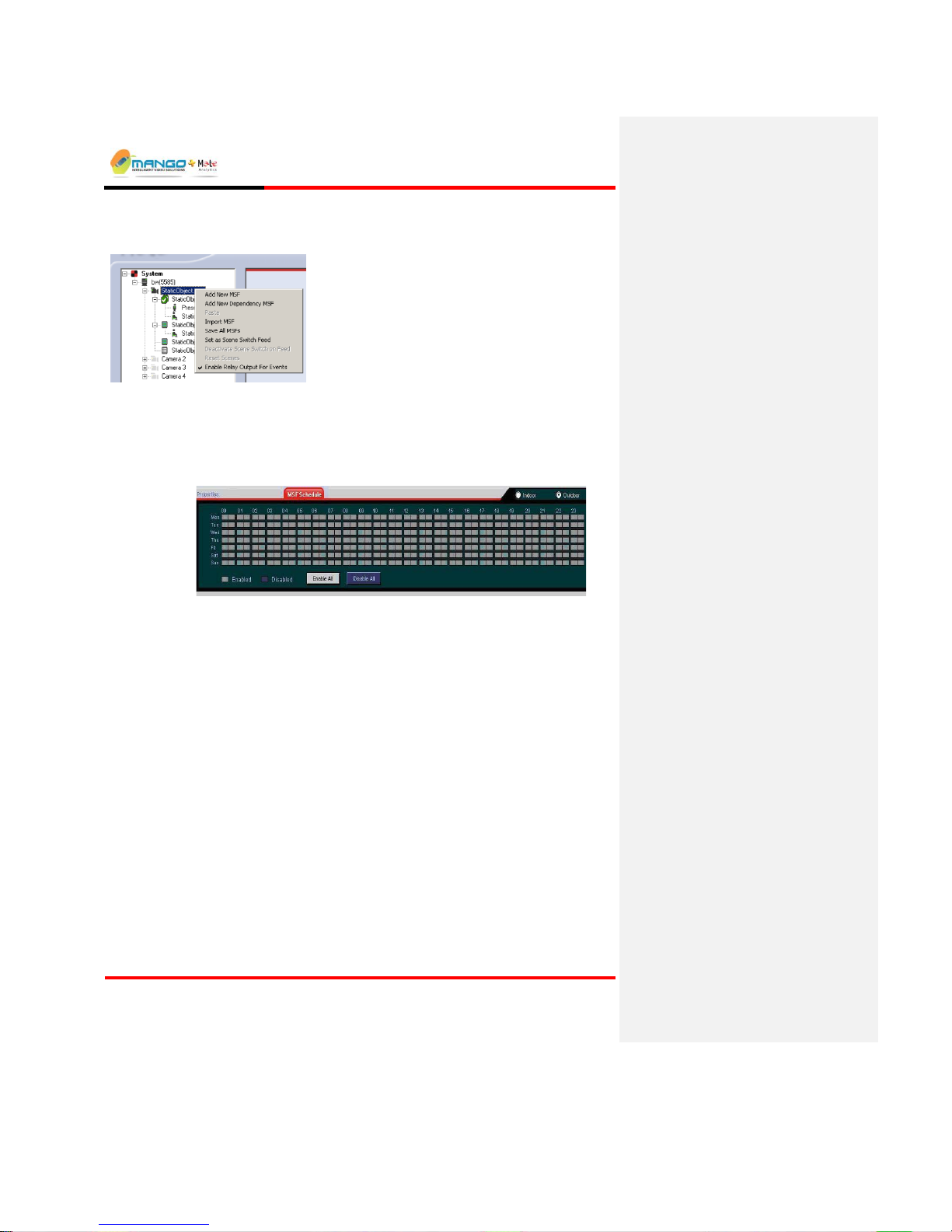
To enable relay output for events:
1. From the Tree View, right click on connected device. The following window appears:
2. Select Enable Relay Outputs for Events.
5.3.4. MSF Schedule Tab
Displays and sets the parameters related to the entire rule set: a surveillance
scheduler and an indoor / outdoor scene selection.
FIGURE 24:MSF SCHEDULE TAB
5.3.4.1. Scheduler Options
The MSF tab displays a scheduler for which you can determine specific days and
times for detecting alarms. The rows in the time table mark the days, whereas the
columns mark the time in 30 minutes intervals. A rubric painted dark blue
indicates it is in disabled mode; a rubric painted light gray indicates it is in
enabled mode. By default, the Enable All button is selected, allowing constant
24/7 alarm generation for each MSF. You can disable alarm notifications for a
selected MSF by clicking the Disable All button.
To determine specific days and time for events detection, first create an MSF;
then follow either of these steps:
In the default mode (Enable All button selected), select the desired day(s)
and time to disable activity by clicking the desired rubrics. You can click and
drag the mouse button to select multiple adjacent rubrics.
Click the Disable All button; then click the desired rubrics to enable alarm
notification (Dragging is not possible in this option).
Click on a rubric alternately to toggle between enable and disable modes.
Page 43

Rules Manager/Device Explorer
V4.5
Page 5-21
5.3.4.2. Indoor/Outdoor Selection
By default, an Outdoor scene is assumed and advanced interference rejection
algorithms are deployed. The Indoor option uses an alternate set of algorithms,
optimized for indoor use.
Note: This setting is defined per MSF and affects all alarms within that MSF.
Note: This feature is very useful in Area Coverage and Motion Activity. (learning
background reference).
5.4. Working with MSFs
An MSF is a file containing an array of alarms defined or "set" per video feed. A
video feed can be assigned an unlimited number of MSF files, but only one MSF
files (in Behavior Watch) but only one MSF can be “loaded” or active at a time.
Saved MSFs are loaded automatically whenever you run the Rules Manager, and
appear in the tree view under the feed for which they were set, displaying the
name of the MSF(s) and the alarm(s) set.
5.4.1. Creating an MSF
When you create an MSF, it will be assigned a default name based on the camera
and feed (or file) information. You can change this default name by clicking the
MSF name field and typing a new name over it, or you can leave the default
name. Identical names cannot be assigned for different MSF files per feed.
To create an MSF:
1. Right click on a feed's name field and select Add New. A window appears
with the selection of Alarm Types.
2. Click on the desired Alarm Type.
3. Click Save MSF.
4. Click Set as Active MSF.
5.4.2. Saving an MSF (BW only)
This option allows you to save the MSF you have created and allow you access to
this set of settings by automatically loading them the next time you run the Rules
Manager.
To save an MSF:
1. On the Rules Manager window, set the alarms for the MSF and assign it a
descriptive name by left clicking its name field in the tree view.
2. Make sure the MSF name field is highlighted by left clicking its name field.
Right click and select Save MSF from the popup menu. The MSF saves to a
file named after the MSF with an .msf extension.
Page 44

Rules Manager/Device Explorer
V4.5
Page 5-22
NOTE:
An unsaved MSF appears with an asterisk (*) next to its name.
5.4.3. Activating/Deactivating a Single MSF
Right click the relevant MSF name field and select Set as Active MSF from the
popup menu. A check appears next to the left of the MSF name field to indicate
it is active. Note that an inactive MSF displays a list icon next to its name field,
indicating that the file is not in active mode.
5.4.4. Activating/Deactivating Multiple MSFs
Up to 5 MSFs can be simultaneously activated as long as there is no conflict in the
times that each of the MSFs are active. This entails the use of the Scheduler
Options (on Page 5-20) to ensure that each of the MSFs is active for a different
time period.
Right click on each of the relevant MSF name fields and select Set as Multiple
Active MSF from the popup menu for each MSF. A double check appears next
to the left of each MSF name field to indicate it is one of the active MSFs.
NOTE:
If a scheduling conflict occurs between an already active MSF and the one being
activated, an error message will appear showing the time(s) of the scheduling
conflict.
5.4.5. Deleting an MSF
To avoid clutter on the Tree View pane, delete obsolete / unusable MSFs. To
delete an MSF, right click the MSF name field and select Remove. Press OK to
confirm the deletion.
5.4.6. Renaming an MSF
The default name given to an MSF displays the following information: device ID,
feed number, MSF number and the ".msf" extension. To rename an MSF, right
click its name field, select Rename and assign it a descriptive name instead of the
default one.
5.4.7. Copy/Paste an MSF
You can Copy/Paste an MSF from one camera to another. This will save time if
there are many cameras with the same settings. To Copy an MSF, right click the
MSF name field and select Copy. Right click another MSF and select Paste.
Page 45

Rules Manager/Device Explorer
V4.5
Page 5-23
5.4.8. Exporting an MSF
You can save an MSF as an accessible file on your computer. Right click the MSF
name field and select Export MSF. Follow the browse dialog to save it in the
desired location on your PC.
5.4.9. Importing an MSF
An MSF can be loaded to the Rules Manager by using the import feature. Left
click to highlight the Feed name field, then right click and select Import MSF. In
the dialog that opens, browse for the saved MSF and click OK. The MSF now
appears in the tree view under the feed's name field.
Verify that the video type/size is the same as the export type/size.
5.5. Working with Alarm Geometries
Video-based detection algorithms analyze a stream of two-dimensional video
images, thereby allowing us to define rules and alarm criteria with high spatial
resolution.
Alarms are geometrically specified in terms of detection zones or object
boundaries, by object sizes with optional perspective and by optional ignore
zones. These parameters are drawn on the video display. The Alarm Geometry
window comprises of a Video Display, Alarm Geometry Tabs (ROI, Object Sizes,
and Ignore Zone) and a tab-sensitive Drawing Toolbar. The Alarm Geometry tabs
are displayed when a specific alarm is highlighted and may vary depending on the
Alarm type.
FIGURE 25:ALARM GEOMETRIES TABS AND THE ROI TOOLBAR
Page 46
Rules Manager/Device Explorer
V4.5
Page 5-24
5.5.1. ROI Tab for Detection Zone Geometry
Select the ROI tab to designate the area of support for the selected alarm type,
using the ROI drawing tools located in the right column.
ROI Drawing tools comprise a rectangle and a polygon .
To draw a rectangle: select the rectangle button and press while dragging
the left mouse button to draw it in the required area. You can resize the shape by
moving the mouse pointer over the edges and then dragging each of its sides to the
desired location.
To draw a polygon: select the polygon button: . Press while dragging the left
mouse button to draw the first line. Continue to create the edges of the polygon by
left clicking the desired vertices. Finally, make sure that the shape drawn is fully
closed: double-click the closing point. The shape becomes slightly colored,
indicating it was created successfully. You can resize the shape by moving the
mouse pointer over the edges and then dragging each of its sides to the desired
location. Note that creating a self-intersecting polygon is not possible.
5.5.2. Object Sizes Tab
When you set an alarm, it is necessary to set minimum and maximum bounds on
the size of subjects to be detected, in order to ignore irrelevant subjects and thus
avoid false alarms.
The bounds are set by a pair of concentric rectangles that represents the maximum
and minimum sizes (horizontal and vertical) of a subject you wish to detect. You
can move the indicators to an image location where it is easier to set the sizes
(possibly pausing the video to a captured object for sizing).
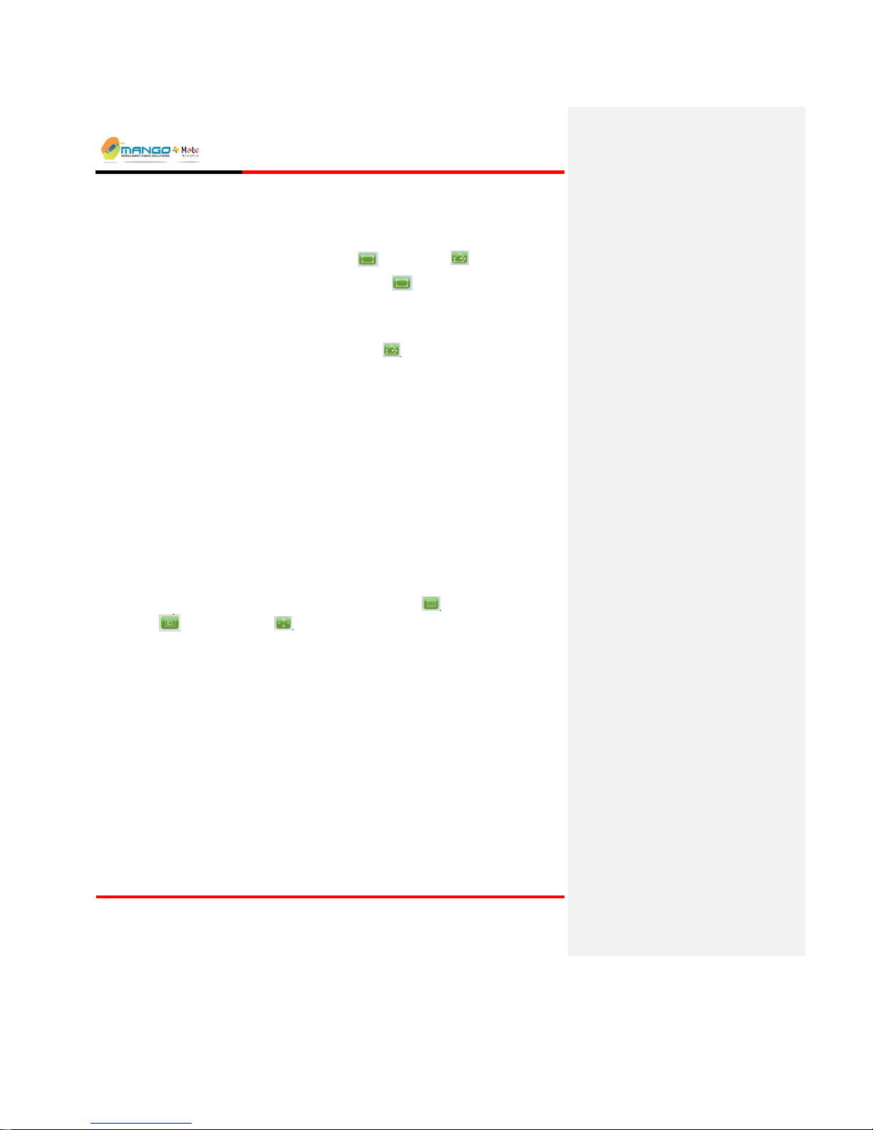
Object Size drawing tools include the Maximum tool , the Minimum tool
, and the Shift tool .
5.5.3. Classification Tab
The Behavior Watch VDUs support the Classification feature which enables
objects detected to be classified as either 'Human', 'Vehicle' or 'Other'. This feature
is only available for the VMD, Path Detection and Static Object alarm types. Note
that Classification is set per MSF and not per individual alarm.
To enable the classification feature, select the Use Classification feature (with or
without perspective) on the Classification tab. The Human size rectangle which
appears can be resized by moving the mouse pointer over the edges and then
dragging each of its sides to the desired dimension. If perspective has also been
selected, the far human size rectangle readjusts automatically as well.
Page 47
Rules Manager/Device Explorer
V4.5
Page 5-25
Allows the Human size rectangle to be adjusted.
This button resets the size to its default value.
Used for undoing the last performed operation (only the last action).
Allows the rectangle to be shifted to an image location where it is easier to set
the size.
NOTE:
Vehicle size is automatically computed from the Human size setting.
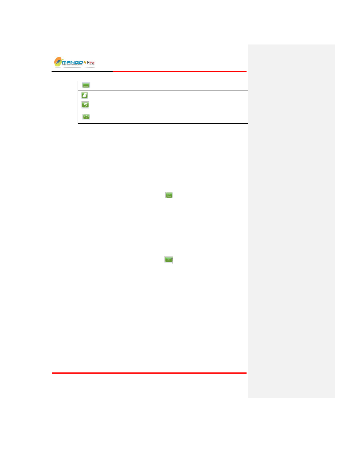
5.5.4. Working without Perspective
To set these bounds for a zone with no perspective distortion:
1. In the Rules Manager window, left click to highlight an alarm name field.
2. Select the Object Sizes tab.
3. Select the Alarm tab, and then select No Perspective (default).
4. Select the Maximum rectangle button from the toolbar. Two rectangular
shapes appear at the center of the frame. The external rectangle determines
the maximum size of the subject, and the internal one determines its
minimum size.
5. In order to resize the external rectangle horizontally, move the mouse pointer
over its left or right edges until a two-headed arrow appears. Then, resize the
shape by left clicking and dragging each of the edges to the left or to the right.
To resize the external rectangle vertically, move the mouse pointer over the
upper or lower sides of the shape and when a two headed arrow appears, left
click and drag the edges upwards or downwards.
6. Select the Minimum rectangle button from the toolbar, and follow the
same resizing guidelines. The size of the minimum rectangle cannot be larger
than the maximum rectangle.
Page 48

Rules Manager/Device Explorer
V4.5
Page 5-26
NOTE:
You can press the Pause/Play button under the camera display and pause
streaming. This way you can drag the indicators to the desired location where a
subject is captured, and set the indicators more accurately.
FIGURE 26: MINIMUM AND MAXIMUM INDICATORS
5.5.5. Working with Perspective
Video images depict a perspective projection of a 3D world captured by the video
camera. The image location of an object depends on its world location as well as
its distance from the camera that controls how large the object looks in the image.
Equally-sized objects that are located at different distances from the camera will
have different sizes in the image. The nearest object will naturally look larger.
This is known as a perspective distortion.
A significant perspective distortion has to be accounted for, or the Object Size
values defined at one image location will be highly inaccurate at other image
locations, resulting in lower detection probability and / or increased false alarm
rate.
Exact calibration of object size may be tedious and may require information that is
not available from the video images only. We have introduced a way of working
with perspective that is simple, yet accurate enough for our robust detection and
tracking algorithms: you set the object size (a pair of concentric rectangles) at the
nearest possible image location in the ROI, and then set the perspective ratio at the
furthest possible image location in the ROI by scaling down the rectangles in
accordance with that ratio.
The minimum and maximum bounds on subject size are then automatically
linearly interpolated at any image point between the nearest and the furthest point.
Note that if object-camera distance variation across the ROI is small compared
with the object-camera distance at any point in the ROI, then perspective
distortion is insignificant and there is no need to account for perspective.
Page 49
Rules Manager/Device Explorer
V4.5
Page 5-27
As different ROIs in the image may have different object sizes and perspective
distortions, the process below iterates for every ROI that depicts a perspective
distortion.
To set Perspective:
1. In the Rules Manager window, left click to highlight an alarm.
2. Select the Object Sizes tab.
3. From the Alarm tab, click With Perspective.
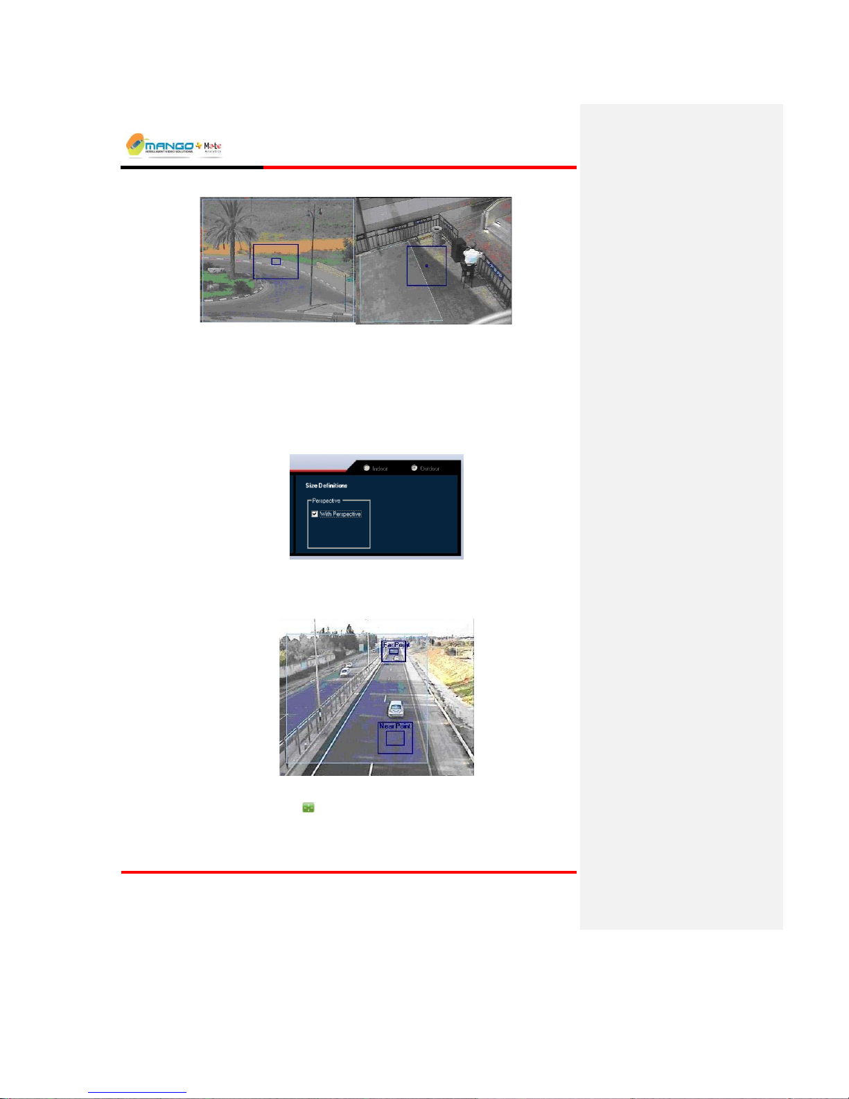
FIGURE 27: PERSPECTIVE
Two pairs of rectangular indicators appear; one pair for a Near point and the other
for a Far Point.
FIGURE 28:OBJECT SIZES
4. Use the Shift button to move the Near point indicator to the nearest
location in the ROI.
5. Set the Maximum rectangle and the Minimum rectangle.
Page 50

Rules Manager/Device Explorer
V4.5
Page 5-28
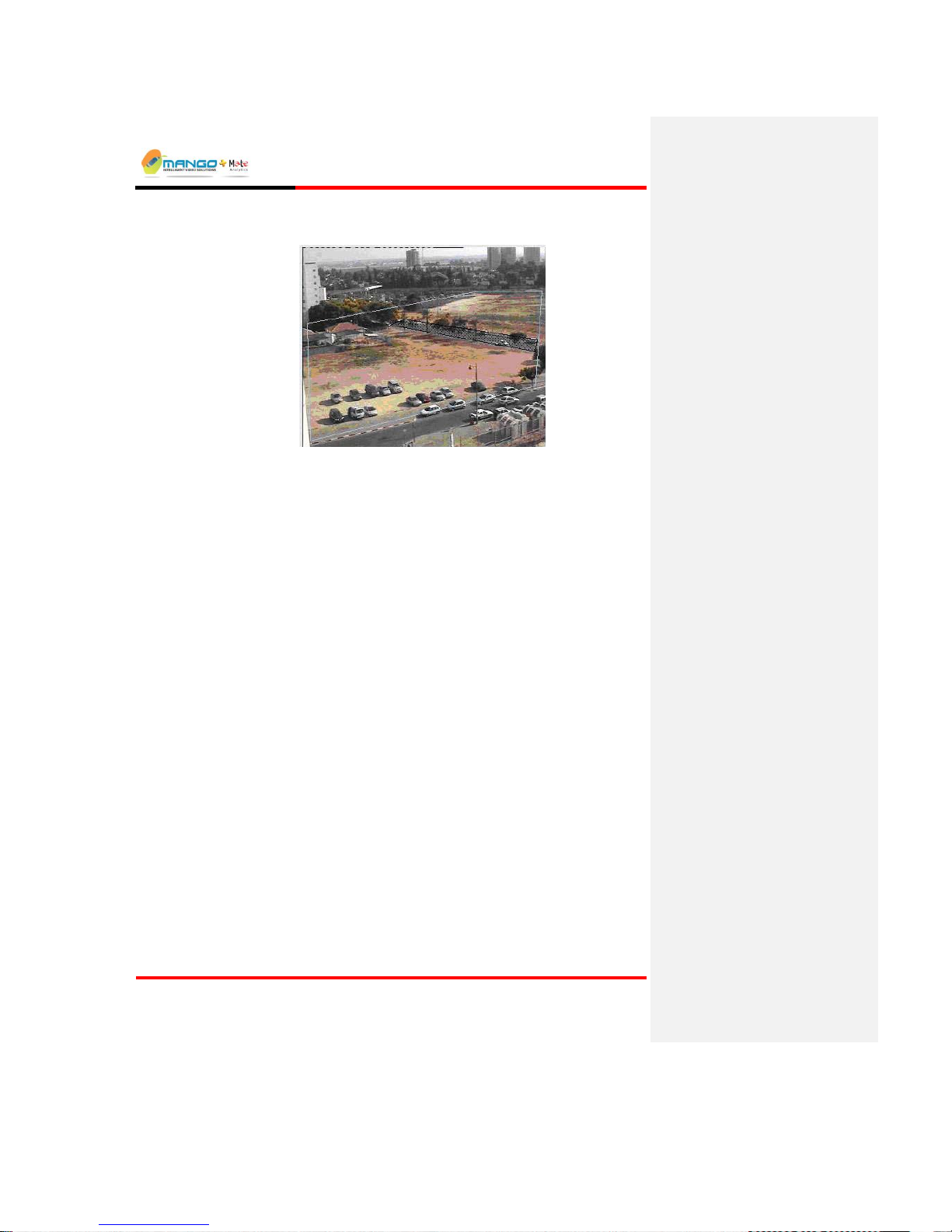
6. Use the Shift button to move the Far point indicator to the furthest
location in the ROI.
7. Select the Maximum button. Drag the edges of the Far Point Maximum
rectangle. The pair of rectangles will scale in accordance with the change in
any dimension of the Maximum rectangle.
5.5.6. Ignore Zone Tab
The Ignore Zone feature is used to define up to three specific areas of an image
where no video analytics will be applied.
IMPORTANT:
Any zone marked to be ignored applies to ALL alarms within that MSF.
Possible usage:
The detection algorithm also detects and tracks subjects outside the detection
zones for improved detection when the subjects enter the zone. Some scenarios
include a high-level of activity that is not related to the desired detection, such as
a road located far from the zone. The ignore zone allows the system to ignore this
area and reduce the computational load for the algorithm.
An ignore zone may encompass a part of a detection zone, when the activity
inside that part is meant to be ignored.
Setting an Ignore Zone:
Drawing tool: Polygon button.
The Eraser button. This button is used for deleting ALL ignore zones.
Used for undoing the last performed operation (only the last action).
When setting an alarm, select the Ignore Zone tab and draw a polygon.
When the polygon is complete, it is filled by a hatched pattern to distinguish
it from a regular detection zone. Up to three separate Ignore Zones can be
created.
Use the Undo button to undo the last polygon edge drawn.
Page 51
Rules Manager/Device Explorer
V4.5
Page 5-29
Use the Eraser button to delete all ignore zones (ignore zones can only be
edited once all three have been created).
FIGURE 29:IGNORE ZONE TOOL
NOTE:
The Ignore zone does not display in the Cortex Viewer.
5.6. Setting Alarms
5.6.1. Optional Settings
Select the Ignore Zone tab if needed, and use the polygon tool to mask an
image area that will be excluded from alarm detection.
Check the Indoor/Outdoor selection and modify it on the MSF Schedule tab
if necessary. This selection will apply to all alarms set in the same MSF.
Change the Sensitivity value on the Alarm tab to High if the detection zone
is environmentally quiet (image wise) and if low-contrast subjects need to be
detected. Alternatively, change Sensitivity to Low if the detection zones and
the encompassing area are environmentally noisy.
5.6.2. Display and Editing Options
Right click the alarm name field for the following options:
Show All ROIs: Displays all detection zones for that MSF.
Hide other ROIs: Hides all other zones for that MSF (zones are still active,
and alarm notifications are still received).
Remove: Deletes the alarm from the tree view.
Rename: Changes the alarm's name.
In addition, it is possible to edit the Sensitivity and Alarm Geometries described
under the corresponding entries.
Page 52

Rules Manager/Device Explorer
V4.5
Page 5-30
5.6.3. Scene Switch Feature
The Behavior Watch VDUs support the operation of multiple preset cameras (e.g.
PTZ Cameras). To activate this feature for a feed, right-click on the feed and
select Set as Scene Switch Feed from the popup menu.
The Rules Manager application will automatically detect each of the preset scenes
(up to a maximum of 4) and each scene will be treated as a separate "feed" for
purposes of adding an MSF, etc. Rules can be added to each scene individually as
normal for a camera feed.
Feature Description:
Extends Behavior Watch video analytics to PTZ cameras or multiple cameras
connected via matrix switcher (virtual switching products).
Automatically identifies up to 4 scenes monitored by the same video feed and
allows you to set video detection rules independently for each such scene.
Once these rules are defined behavior watch automatically recognizes the
scene and applies the respective rules set, taking into accounts object data
gathered during past visits to the same scene.
Applicable rules include object started, static object, object removal, VMD
and presence
The Rules Manager application will automatically detect each of the preset
scenes (up to 4) and each scene will be treated as a separate "feed" for
purposes of adding an MSF, etc. Rules can be added to each scene
individually as normal for a camera feed.
Feature performance specification:
Page 53

Rules Manager/Device Explorer
V4.5
Page 5-31
Up to 4 scenes per feed
Minimal visit time: 10 seconds
Consistent visit order, visit duration may vary
Duration of tour/switching cycle < 2 minutes
Fast recovery
Reset recovery
Configuration:
Click Set as Scene Switch Feed or Reset Scenes
Page 54

Rules Manager/Device Explorer
V4.5
Page 5-32
To add MSF click Add New MSF and click on Scene
NOTE:
This feature works identically with Virtual Switching products.
This feature is license dependent and runs both on BW and Trigger T1S.
Requires license of Max Allowed Scenes.
Page 55

Rules Manager/Device Explorer
V4.5
Page 5-33
Alarm Types
The following table displays which alarm types are currently supported by the
various VDUs:
ALARM TYPE
BEHAVIOR
WATCH
TRIGGER
NG
ISENSE
VMD
Static Object
Presence
Path Detection
Object Started
Directional Motion
Loitering
Speed
Object Removal
Area Coverage
Motion Activity
People Counting
Car Counting
Access Watch
The Rules Manager application automatically identifies each type of VDU, and so
only the relevant Alarm Types will be accessible on the sub-menu for adding an
alarm to an MSF.
NOTE:
All alarms are license dependent.
In Trigger NG counting cannot operate simultaneously with other surveillance
rules but can be scheduled to work at different time slots.
5.6.4. VMD (Video Motion Detection) Alarm
Description:
The VMD Alarm is activated whenever a subject is moving inside the detection
zone.
Possible uses:
Perimeter surveillance: Monitor the area between two physical or virtual
fences for detection of object motion in said area that constitutes a perimeter
breach.
Page 56

Rules Manager/Device Explorer
V4.5
Page 5-34
Peripheral protection: Monitor the area around an asset or resource for
detection of objects that approach said asset or resource.
Wide area surveillance: Monitor a large area for early warning and detection
of intrusions.
To Set the VMD Alarm:
1. Right click the MSF name field, select Add New and then VMD.
2. Select the ROI tab, and use one of the drawing tools (rectangle / polygon) to
draw the desired shape of the ROI.
3. Select the Object Sizes tab to define the minimum and maximum size of the
detected subject with optional perspective adjustment.
FIGURE 30:VIDEO MOTION DETECTION ALARM
NOTE:
This alarm supports Classification (see "Classification Tab" on Page 5-24),
which enables objects detected to be classified as either 'Human', 'Vehicle' or
'Other'.
5.6.5. Static Object Alarm
Description:
The Static Object Alarm activates an alarm upon detection of a subject that
remains in a same image position more than a user-specified time limit. Static
objects may be detected in scenes with multiple moving objects and even in the
case of temporary occlusions by these moving objects.
Possible uses:
Stopped vehicle: detecting vehicle incidents / threats on roads, road
shoulders, tunnels and other critical locations.
Fallen cargo: identifying on-road hazards created by objects falling off
vehicles.
Tossed object: detecting packages with illegal / hazardous contents thrown
over the fence into the perimeter or the site.
Page 57
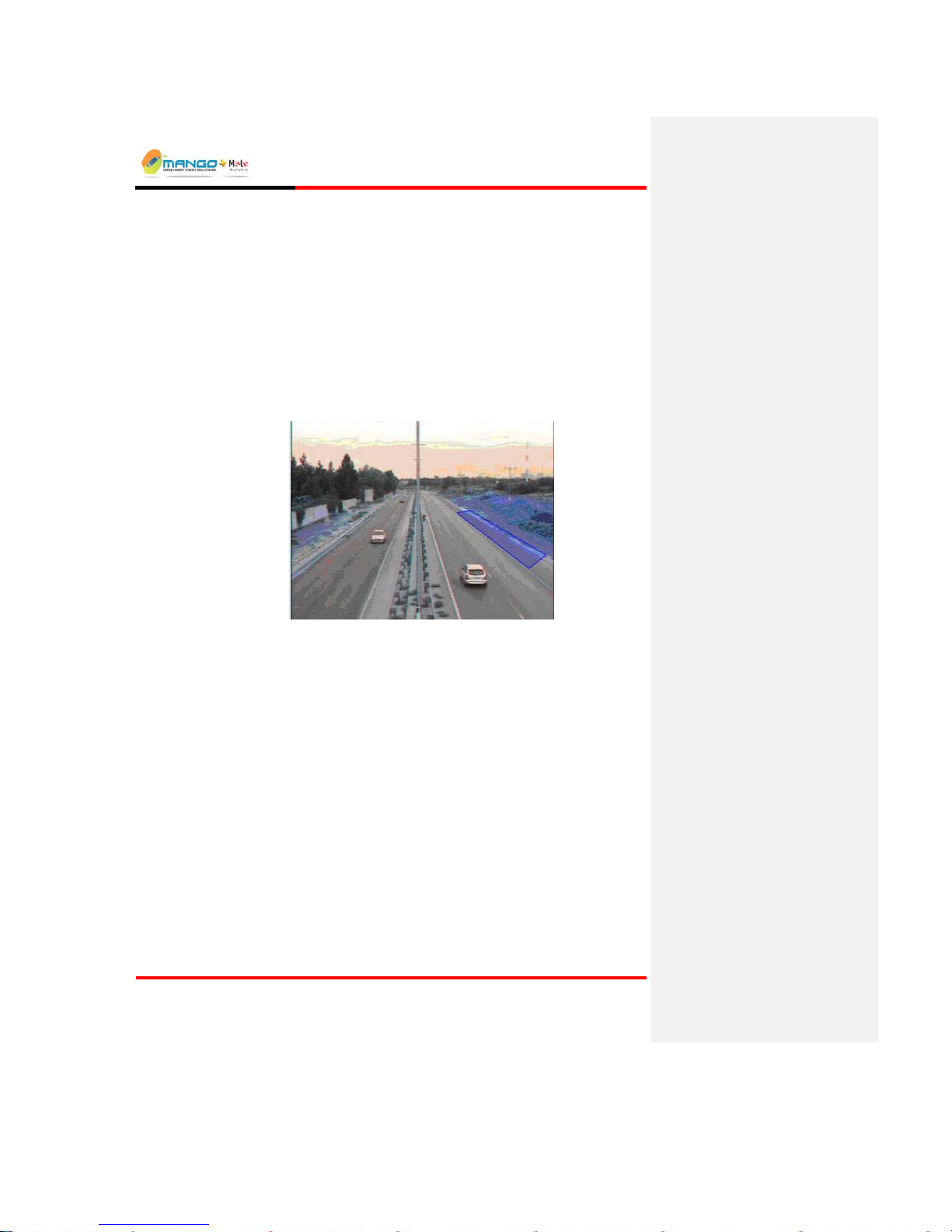
Rules Manager/Device Explorer
V4.5
Page 5-35
Abandoned object: detecting packages / objects left by moving pedestrians in
a public venue.
To Set the Static Object Alarm:
1. Right click the MSF name field, select Add New and then Static Object.
2. Select the ROI tab, and use one of the drawing tools (rectangle / polygon) to
draw the desired shape of the ROI.
3. Select the Object Sizes tab to define the minimum and maximum size of the
detected subject with optional perspective adjustment.
4. Set the Time to Alert. In the Alert will be activated after… seconds field,
set the number of seconds (10 to 1800) to wait before activating an alarm (the
default is 30 seconds).
FIGURE 31:STATIC OBJECT ALARM
NOTE:
This alarm supports Classification (see "Classification Tab" on Page 5-24),
which enables objects detected to be classified as either 'Human', 'Vehicle' or
'Other'.
5.6.6. Presence Alarm
Description:
The Presence Alarm alerts on any object inside the detection zone to achieve
maximum detection sensitivity.
Possible uses:
Detect intrusion into restricted areas: Viewing a relatively small area where
presence of people/objects is prohibited; alerts on the appearance of a person
in a window or a doorway.
Page 58
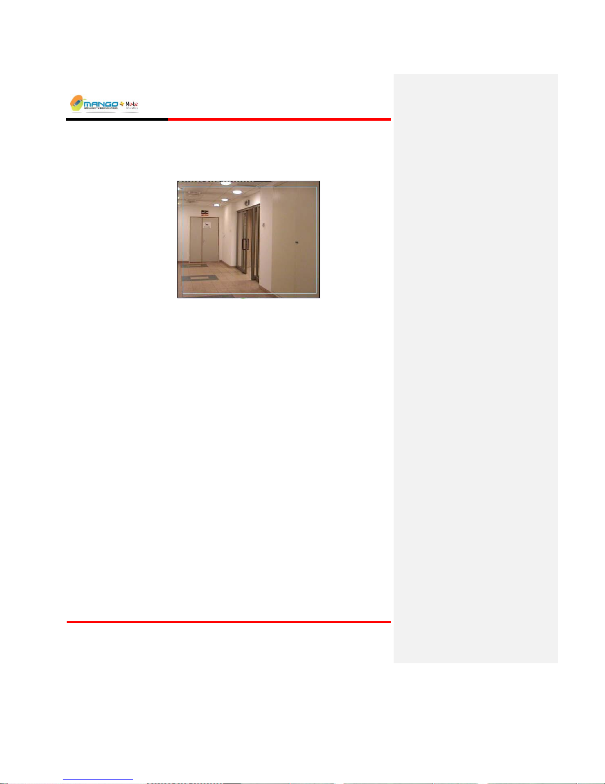
Rules Manager/Device Explorer
V4.5
Page 5-36
Detect intrusion into high-occlusion areas: Detect objects in highly-occluded
areas due to background objects in multiple depth arrangement such as an
open space with furniture and cubicle walls.
FIGURE 32:PRESENCE ALARM
To Set the Presence Alarm:
1. Right click the MSF name field, select Add New and then Presence.
2. Select the ROI tab, and use one of the drawing tools (rectangle / polygon) to
draw the desired shape of the ROI.
3. Select the Object Sizes tab to define the minimum and maximum size of the
detected subject with optional perspective adjustment. Note that alarm
definition is not complete until you define these sizes.
5.6.7. Path Detection Alarm
Description:
Path Detection alarms are used to detect whenever a subject crosses from one area
to another in one specified direction or in both directions. A subject is first
detected in a "source" zone and its motion is tracked to the detection zone. An
alert is issued when the object moves into the detection zone.
Possible usages:
Boundary crossing: Placing both zones nearby triggers an alarm immediately
when the object moves from the source zone into the detection zone. To avoid
the ambiguity that may be encountered when an extended object is
"wandering" around the boundary, the source zone may be displaced from the
detection zone by a distance comparable to the object size.
Motion pattern: In this use case the source zone may be placed in any image
location relative to the detection zone provided that the object is tracked
between the two zones.
Page 59

Rules Manager/Device Explorer
V4.5
Page 5-37
2-way path detection: Triggers alarm in the use cases above, irrespective of
the path direction: source zone to detection zone or vice versa.
FIGURE 33:PATH DETECTION ALARM
To Set the Path Detection Alarm:
1. Right click the MSF name field, select Add New and then Path Detection.
2. Select the ROI A tab and use the drawing tools to draw a first detection zone.
The letter "A" appears at the top of the drawn ROI.
3. Select the ROI B tab and use the drawing tools to draw a second detection
zone. The letter "B" appears at the top of this ROI.
4. On the Alarm tab, select the direction to be monitored: Both (A to B or B to
A), From A to B only, or From B to A only.
5. Select the Object Sizes tab to define the minimum and maximum size of the
detected subject with optional perspective adjustment.
NOTE:
This alarm supports Classification (see "Classification Tab" on Page 5-24),
which enables objects detected to be classified as either 'Human', 'Vehicle' or
'Other'.
5.6.8. Object Started Alarm
Description:
The Object Started alarm activates whenever a static object is displaced from its
fixed position within the detection zone.
Possible uses:
To supervise objects that should remain stationary (for example, a car in a private
parking place). In the figure below, a car can enter the ROI, however, an alarm
Page 60
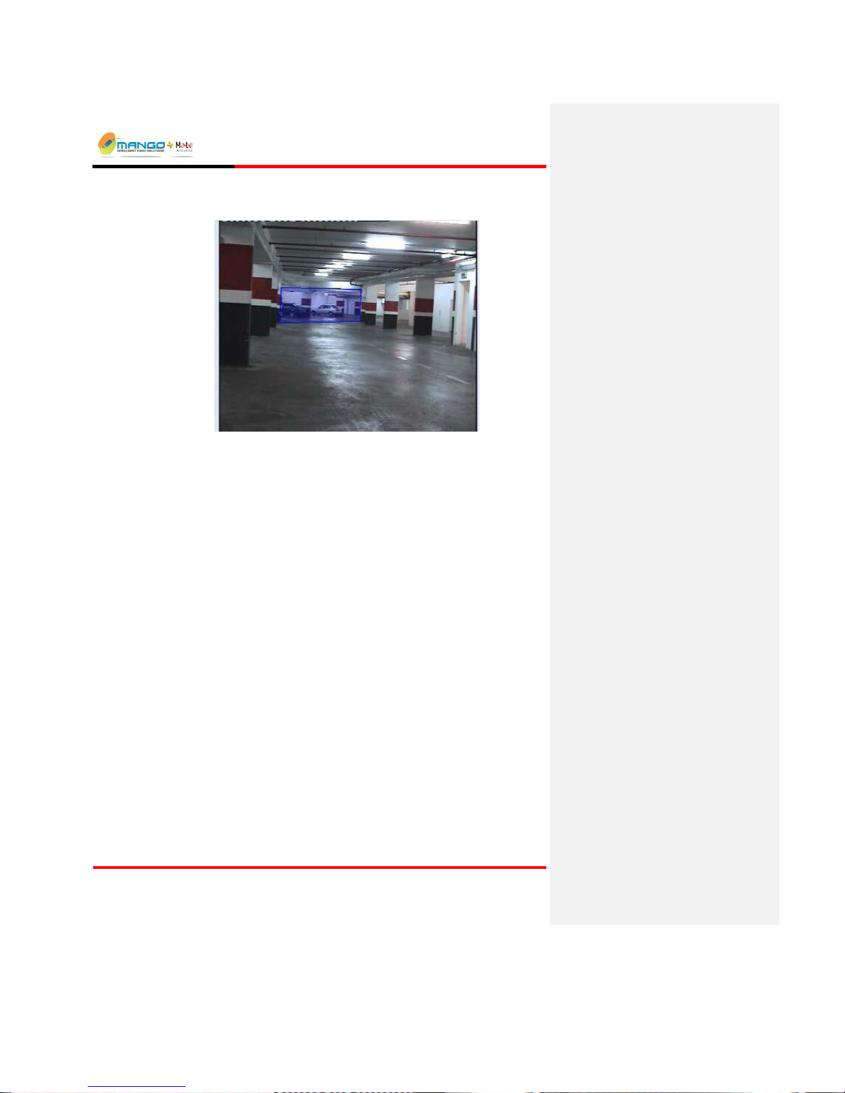
Rules Manager/Device Explorer
V4.5
Page 5-38
notification will be sent once it fully stops and then starts moving inside or outside
the ROI.
FIGURE 34:OBJECT STARTED ALARM
To Set the Object Started Alarm:
1. Right click the MSF name field, select Add New and then Object Started.
2. Select the ROI tab, and use one of the drawing tools (rectangle / polygon) to
draw the desired shape of the ROI.
3. Select the Object Sizes tab to define the minimum and maximum size of the
detected subject with optional perspective adjustment.
5.6.9. Directional Motion Alarm
Description:
The Directional Motion alarm is activated whenever a subject travels in a
direction within a predefined angular sector (continuous range of angles).
Possible uses:
Wrong way – people: Detect people traveling the wrong way in busy
environments, such as airport security exits.
Wrong way – vehicles: Detect vehicles traveling the wrong way in roads in
order to enforce traffic rules.
Page 61
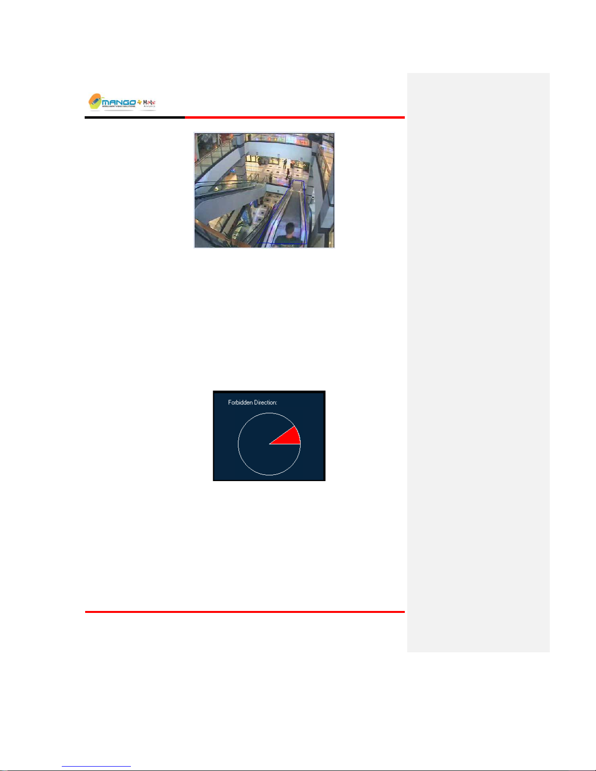
Rules Manager/Device Explorer
V4.5
Page 5-39
FIGURE 35:DIRECTIONAL MOTION ALARM
To Set the Directional Motion Alarm:
1. Right click the MSF name field, select Add New and then Directional
Motion.
2. Select the ROI tab, and use one of the drawing tools (rectangle / polygon) to
draw the desired shape of the ROI.
3. Select the Object Sizes tab to define the minimum and maximum size of the
detected subject with optional perspective adjustment.
4. In the Alarm tab at the bottom window, set the Forbidden Direction angular
sector to alert on motion in these directions. Move the mouse pointer to the
edges of the circle and drag them to create the desired angle.
5.6.10. Loitering Alarm
Description:
The Loitering alarm is activated whenever a subject remains inside the detection
zone for a specified period of time.
Possible uses:
Perimeter surveillance: Monitor the area between two physical or virtual
fences for detection of loitering in said area.
Page 62
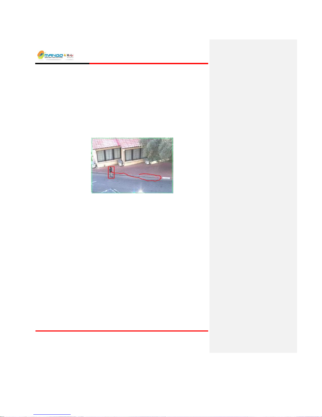
Rules Manager/Device Explorer
V4.5
Page 5-40
Peripheral protection: Monitor the area around an asset or resource for
detection of suspicious objects that approach said asset or resource.
To Set the Loitering Alarm:
1. Right click the MSF name field, select Add New and then Loitering.
2. Select the ROI tab, and use one of the drawing tools (rectangle / polygon) to
draw the desired shape of the ROI.
3. Select the Typical Size tab and adjust the size of the rectangle to match the
typical size of a person in the video image.
4. On the Alarm tab, select the amount of time (between 10 and 600 seconds)
that constitutes loitering.
FIGURE 36:LOITERING ALARM
NOTE:
Only one Loitering Alarm can be added to a particular MSF. It is also
recommended not to add other Alarm Types to the MSF (results in a degradation
of system performance).
5.6.11. Speed Alarm
Description:
The Speed Alarm measures speed and activates an alarm whenever a subject or a
vehicle violates the designated speed bounds. Speed is measured indirectly by
measuring the travel time between two zones. If the ground distance between the
zones is known, actual speed values may be derived. For example, suppose that
the ground distance between the zones (say A and B) is 100m and that a vehicle
has traveled that distance in less than 4 seconds. In such a case, the vehicle has
certainly exceeded a speed limit of 25m/sec or 90 Km / Hour when traveling from
A to B.
Possible uses:
Detecting speed disparities of subjects and vehicles: speeding or traveling too
slowly.
Page 63
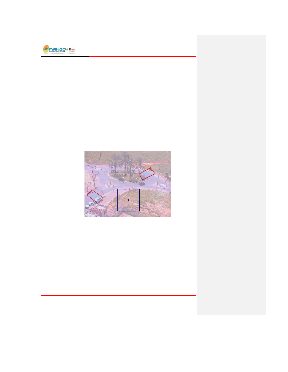
Rules Manager/Device Explorer
V4.5
Page 5-41
To Set the Speed Alarm:
1. Right click the MSF name field, select Add New and then Speed.
2. Select the ROI A tab and use the drawing tools to draw a first detection zone.
The letter "A" appears at the top of the drawn ROI.
3. Select the ROI B tab and use the drawing tools to draw a second detection
zone. The letter "B" appears at the top of this ROI.
4. On the Alarm tab, select the direction the subject must travel in order to
trigger the alarm: Both Directions, from A to B or from B to A.
5. On the same tab, set the Travel Time:
In the Min field set the minimum allowed travel time (0 to 500 seconds). Travel time
below the Min value (default is 0 seconds) will trigger an alarm.
In the Max field set the maximum time to wait 0 to 500 seconds) before activating an
alarm (default is 500 seconds).
6. Select the Object Sizes tab to define the minimum and maximum size of the
detected subject with optional perspective adjustment.
FIGURE 37:SPEED ALARM
5.6.12. Object Removal Alarm
Description:
The Object Removal Alarm activates an alarm whenever a designated object is
fully removed from the specified ROI, and the background behind it (where the
subject was originally located) is visible. Optionally, an alarm is activated
whenever the object is hidden for more than a pre-defined number of seconds.
Possible uses:
To safeguard a sensitive object (an expensive painting for example) that should
not be removed from a designated place.
Page 64

Rules Manager/Device Explorer
V4.5
Page 5-42
To Set the Object Removal Alarm:
1. Right click the MSF name field, select Add New and then Object Removal.
2. In the ROI tab select one of the drawing tools from the toolbar to draw the
desired shape of the ROI around the object. To tightly bind the object
contour, proceed by clicking anywhere inside the zone (but outside the object
itself) for the object to be encompassed more tightly.
3. In the Alarm tab, set the Time to Alert of Hidden Objects: In the Alert will
be activated after… seconds field, set the number of seconds (10 to 300) to
wait before the object's occlusion activates an alarm (default is 30 seconds).
FIGURE 38:OBJECT REMOVAL ALARM
NOTE:
In the Object Removal Alarm, perspective and Min/Max parameters are of no
relevance; therefore they do not appear in the alarm tabs.
5.6.13. Area Coverage Alarm
Description:
The Area Coverage alarm will be activated when coverage is over or under a
percentage of the region of interest.
Possible Uses:
Ideal for use at airports, seaports, stadiums, highways, or any other areas where
people or vehicles gather.
To Set the Area Coverage Alarm:
1. Right click the MSF name field, select Add New and then Area Coverage.
2. Select the ROI tab, and use one of the drawing tools (rectangle / polygon) to
draw the desired shape of the ROI.
Page 65
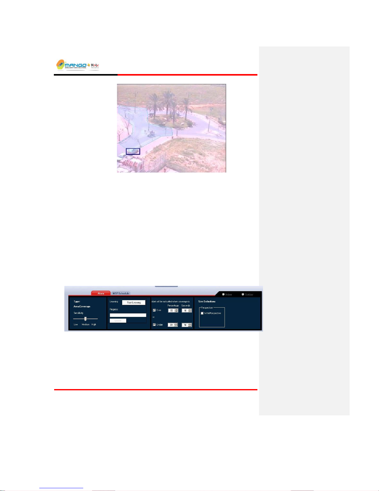
Rules Manager/Device Explorer
V4.5
Page 5-43
1.
3. Select the Typical Size tab and adjust the size of the rectangle to match the
typical size of a person or vehicle in the video image.
4. On the Alarm tab:
Set the Area Coverage Type Sensitivity to Low, Medium, or High.
Set the Alert will be activated when coverage is in percentage and
seconds for both over and under.
Note: You must enter a number the coverage for percentage and seconds for
both over and under before you can start learning.
Click the Start Learning button. The Rules Manager application will then go through
a process of learning the background (static) scene. Keep the scene clear of objects
until the background has been learned.
NOTE:
Indoor/Outdoor selection is important; Outdoor mode has to learn the
background.
FIGURE 39:AREA COVERAGE ALARM
5.6.14. Motion Activity Alarm
The Motion Activity Alarm is the same as the Area Coverage except that it is not
static. The Area coverage analyzes the standing or total coverage while the
Motion Activity analyzes moving objects.
Page 66

Rules Manager/Device Explorer
V4.5
Page 5-44
Possible Uses:
Ideal for use at airports, seaports, stadiums, highways, or any other areas where
people or vehicles gather.
To Set the Motion Activity Alarm:
1. Right click the MSF name field, select Add New and then Motion Activity.
2. Select the ROI tab, and use one of the drawing tools (rectangle / polygon) to
draw the desired shape of the ROI.
3. Select the Typical Size tab and adjust the size of the rectangle to match the
typical size of a person or vehicle in the video image.
4. On the Alarm tab:
Set the Motion Activity Type Sensitivity to Low, Medium, or High.
Set the Alert will be activated when coverage is in percentage and
seconds for both over and under.
NOTE:
Indoor/Outdoor selection is important; Outdoor mode has to learn the
background.
FIGURE 40:MOTION ACTIVITY ALARM
5.6.15. Creating a Dependency MSF
A Dependency MSF is a special type of MSF that will only trigger an alarm based
on particular Operation Types as follows:
And: Creates a dependency between 2 alarm rules such that an alarm is only
generated when both rules are triggered - within a specified time period.
Then: Creates a dependency between 2 alarm rules such that an alarm is only
generated when one rule is triggered followed by the other triggered afterwards
- within a specified time period.
Repeat: Creates a dependency on 1 alarm rule such that an alarm is only
generated when the rule is triggered a specified number of times - within a
specified time period
Single: Creates no dependency. An alarm is generated as soon as the rule is
triggered
Page 67

Rules Manager/Device Explorer
V4.5
Page 5-45
Greater: (Access Watch Only) - Creates a dependency between 2 alarm rules
such that an alarm is only generated when one rule is triggered more times than
another rule within a specified period of time.
Note: Up to 3 dependency rules can be created to operate simultaneously.
Note: Not relevant for iSense Counting.
Note: Dependency feature is license dependent.
To create a dependency MSF:
1. Right click on a feed's name field and select Add New Dependency MSF.
A dependency MSF is added to the Tree View list.
When you create an MSF, it will be assigned a default name based on the camera
and feed (or file) information. You can change this default name by clicking the
MSF name field and typing a new name over it, or you can leave the default name.
Identical names cannot be assigned for different MSF files per feed.
FIGURE 41: DEPENDENCY
Page 68

Rules Manager/Device Explorer
V4.5
Page 5-46
2. Add the Alarm TypesAlarm Types to be made dependent.
3. Select the Dependency tab and click Add Rule.
The Advanced Dependency window opens.
4. Enter the Sequence Name. The Sequence Name is the name of the
dependency rule (the default may be changed).
5. Select the Operation Type from the drop down list: Single, And, Then,
Repeat, Greater.
Formatted: Font: Bold, Complex Script Font: Bold
Page 69

Rules Manager/Device Explorer
V4.5
Page 5-47
6. Enter the Event Validity (Dwell Time) in seconds (except for Single). The
Dwell Time is the time period to apply to the dependency rule. It is the time
between the start the first alarm to the start of the last alarm in the dependency
group. All events must start within the dwell time specified.
7. If When Alarms Are Active is enabled, all the alarms in the dependency
group must be active simultaneously during the dwell time.
8. For Operation Type Repeat select the number of repetitions from the
Repetitions drop down list. Repetitions are the number of times the rule must
be triggered before generating an alarm.
9. Click Show Advanced Settings. The following is added to the Advanced
Dependency window.
10. Select the check box to enable Send Dependency Event to External
Devices. If this is not checked, no event will be sent to either the viewer or
Metadata, but will be internal to the specific device.
11. Enter a time in seconds from the Minimum Time Before Creating Similar
Dependency Event drop down list.
12. Click Add. The Argument of Dependency window appears.
The Alarm Name can be selected from the list of Alarms in the Alarm Name drop
down list.
Page 70

Rules Manager/Device Explorer
V4.5
Page 5-48
13. Click Show Advanced Settings to input cross device arguments/alarms.
The advanced settings appear on the Argument of Dependency window. The
advanced settings allow you to add alarms from other devices.
14. Enter Feed Number and Device ID. The dependency can be cross feed and
cross device. If the device ID is of an external device enter a new Alarm
Name.
15. Select the Alarm Name to add the alarm name of the other device.
Additional Alarm Types for external devices are:
Dry Contacts: TTL inputs on Trigger
Counting Event: Count the number of people or cars
16. Enable Continuous Input Event Mode as a single event or multiple events
during dependency. A single event will trigger an alarm when the first alarm
occurs. Multiple events will trigger an alarm each time an alarm occurs within
the specified time.
Page 71

Rules Manager/Device Explorer
V4.5
Page 5-49
17. Enable the Reverse Logic (NOT) to enable a reverse logic condition. This
will automatically enable Multiple events during dependency.
18. Click OK. The rule is added in the Dependency tab.
19. Repeat for each dependency required (up to 3 can operate simultaneously).
Use the Edit Rule button to make changes to a selected dependency rule, and
the Remove Rule button to delete the selected dependency rule from the list.
20. Click Saving an MSFSaving an MSF and Activating/Deactivating a Single
MSFActivating/Deactivating a Single MSF.
Formatted: Font: Bold, Complex Script Font:
Bold
Formatted: Font: Bold, Complex Script Font:
Bold
Page 72

Rules Manager/Device Explorer
V4.5
Page 5-50
5.6.16. People Counting
Description:
People Counting is used for the real-time detection and counting of people in
video images, converting video data into real-time counting information and
storing it in a central database.
Possible uses:
Assisting retailers in reducing costs with hourly/daily/monthly data.
Detecting theft and fraud based on traffic data.
Effectively managing sales and service personnel by comparing traffic with
point-of-sale information.
Improving safety and control at large public areas like stadiums or malls.
To Set People Counting:
1. Right click the MSF name field, select Add New and then People Counting.
2. Select the ROI tab and adjust the counting bar as required. Select the U-shape
mode when a simple horizontal counting bar is not sufficient and a U-shaped
counting bar will more accurately count people in the scene.
3. On the Alarm tab:
4. Select the Flow Direction as appropriate.
5. Select whether to expect shopping carts in the scene.
Page 73

Rules Manager/Device Explorer
V4.5
Page 5-51
6. Click the Start Learning button. The Rules Manager application will then go
through a two-stage process of first learning the background (static) scene, and
then learning the average size from people passing. Keep the scene clear of
people for the first phase (the Next button will become enabled once enough
of the background has been learned), and then have people moving in the
scene for the second stage. Wait until the process completes before saving
and/or activating the MSF (the process cannot complete while below 50%).
FIGURE 42:PEOPLE COUNTING
5.6.17. Car Counting
Description:
Car Counting is used for the real-time detection and counting of cars in video
images, converting video data into real-time counting information and storing it in
a central database.
Possible uses:
Improving safety and control at large public areas with large parking facilities
like stadiums or malls.
Providing an independent audit of entries and exits for comparison with
reported data at commercial lots.
To Set Car Counting:
1. Right click the MSF name field, select Add New and then Car Counting.
2. Select the ROI tab and adjust the counting bar as required.
3. Select the Typical Size tab and adjust the size of the rectangle to match the
typical size of a car in the video image.
4. On the Alarm tab:
Formatted: Font: Bold
Page 74
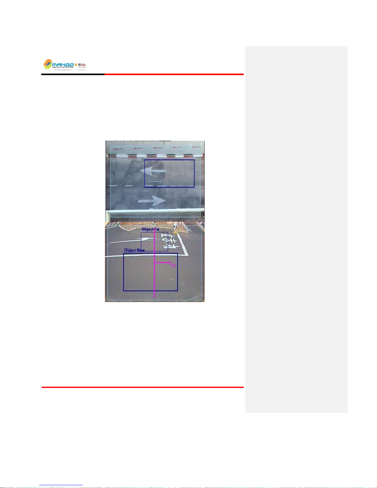
Rules Manager/Device Explorer
V4.5
Page 5-52
Select the Car Direction as appropriate.
Select whether the camera views the scene from the Top or from the
Side.
5. Click the Start Learning button. The Rules Manager application will then go
through a process of learning the background (static) scene. Keep the scene
clear of cars (the Finish button will become enabled once enough of the
background has been learned). Wait until the process completes before saving
and/or activating the MSF.
FIGURE 43:CAR COUNTING TOP AND SIDE
Page 75

Rules Manager/Device Explorer
V4.5
Page 6-53
6. ACCESS WATCH (TAILGATING)
6.1. Application Description
Access Watch is a combined video content analysis and access control solution
for real-time tailgating detection, by simultaneously analyzing video data from
two different cameras focused on the same access point and comparing it to the
data received from the access control device.
6.2. Tailgating Detection
Tailgating is the practice of following an authorized and credentialed
individual through an access control point without having or using a separate valid
credential. This evasive practice compromises all security control measures;
therefore detecting tailgating is critical for secure access control. Tailgating is
characterized by the number of people entering being greater than the number of
cards swiped. Configuring tailgating alarm will notify accurately and promptly
when a violation occurred.
6.3. Principle of Operation
Access Watch combines a very accurate video-based directional counting of
people and groups of people with access control integration to detect and alert
upon cases when the number of cards swiped is less than the number of people
counted. As collaborative piggybacking may be too close to call by a single side
view, or a top view camera, Access Watch provides a unique solution to that
problem.
Unlike portals and man-traps, Access Watch does not reduce throughput, as it
“passively” watches the normal access process, alerting only when a violation has
been detected.
Page 76

Rules Manager/Device Explorer
V4.5
Page 6-54
6.4. Architecture
Our solution uses top and side view cameras located above and nearby the entrance counting
the number of people passing by, a TTL used to notify the edge device about each approved
entering and a TTL used to move the edge device between ready and standby states.
A violation event appears whenever counted number of people is greater than the number of
approval events on a given timeslot, as long as the system is in a ready state.
6.5. Camera Installation
Correct camera positioning and installation is the key to obtaining optimum system
performance as follows:
Page 77
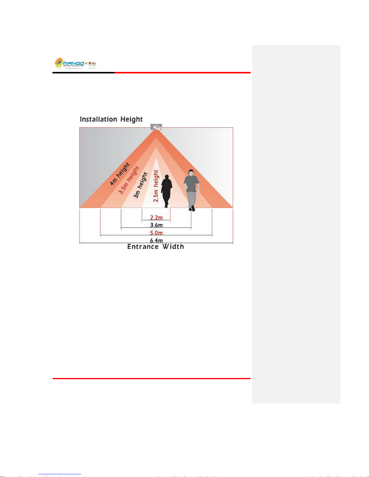
Rules Manager/Device Explorer
V4.5
Page 6-55
1. For accurate detection, minimum camera height of the Primary Camera (the
distance from the bottom of the lens to the floor) should be 2.5m or 8ft, and the camera should
point vertically downwards (see diagram below).
2. Please make sure the Secondary Camera is aligned to the same direction as the first camera,
e.g. people move from left to right.
3. Accuracy can be reduced by reflections from the floor and by hard shadows. Position the
camera and optional lighting sources to minimize these factors.
4. Make sure the people to be detected are fully visible in the image, even when traveling near
the edges of the detection zone. Increase the height of the camera or change its lens if
required.
6.6. Dependency Rule Topology (MSF Description)
We will use a template MSF for Access Watch rules manipulation. This msf will be provided
when receiving a tailgating license as it allows easy installation.
Page 78
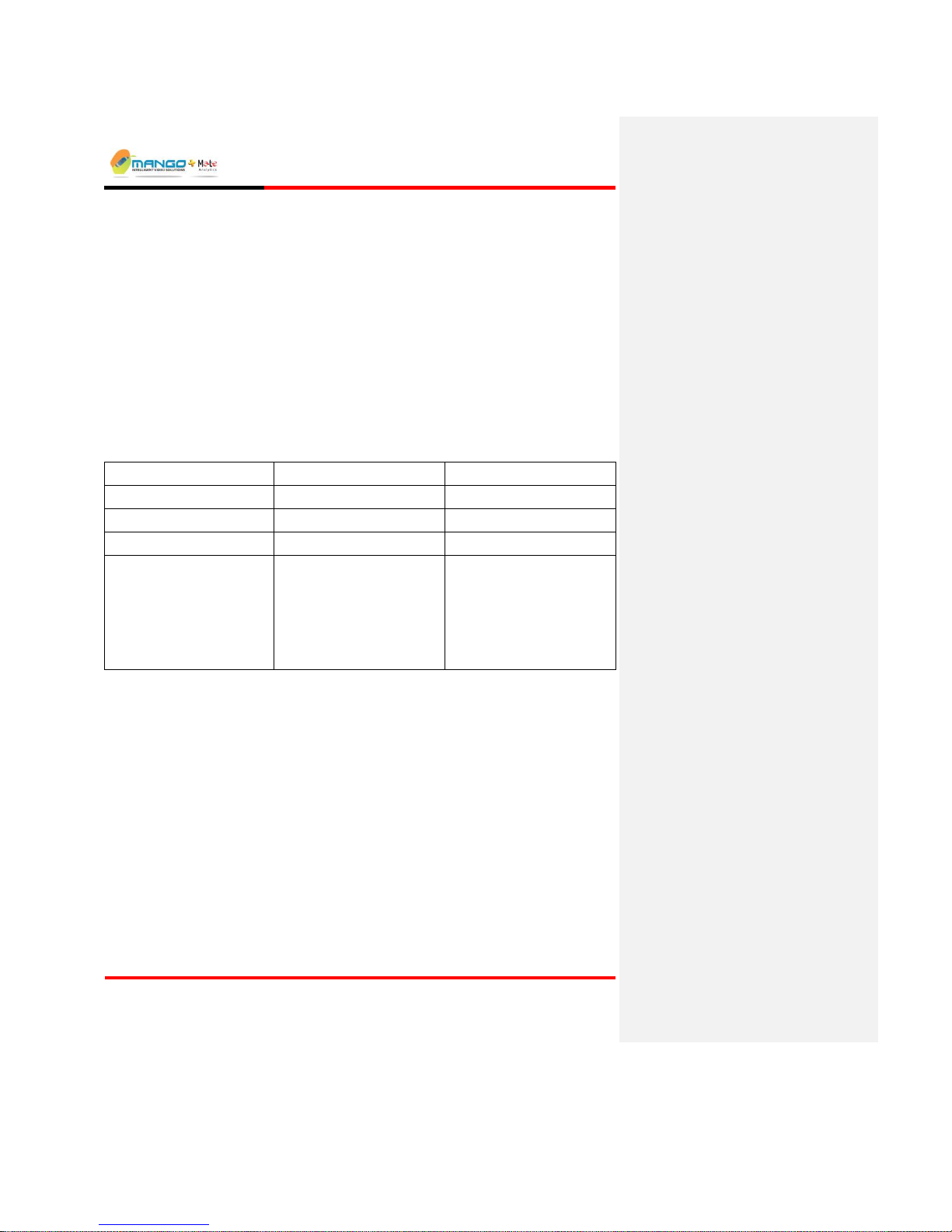
Rules Manager/Device Explorer
V4.5
Page 6-56
Upon receiving such MSF do the following:
1) Import appropriate msf to feed1 (top view camera) and to feed2 (side view camera).
2) Update the ROI on both feeds.
3) For top view learning counting alarm, do learning.
4) Activate the MSF's.
Please notice that the tailgating MSF will work only if your license supports dependency,
people counting and tailgating licenses.
Below we explain in detail what the MSF's define:
Following table describes system inputs:
Channel name
Channel description
Abbreviations
Video In Feed 1
Top view camera
V1
Video In Feed 2
Side view camera
V2
TTL Channel 1
System state device
TTL1
TTL Channel 2
External verification device.
Each event should be
signaled by a 600ms high
level pulse followed by a
600ms zero level.
TTL2
The rationale is to create for each feed an alarm if number of people counted is greater than
the number of cards swapped (number of cards swapped is received through TTL input #2).
We do this for both top-view-camera (V1) and side-view-camera (V2). We then do an OR
between both alarms (effectively by giving them the same name of 'AccessWatchFeed' and
doing a single event to rename it as 'AccessWatch'), and we do AND to verify that the system
is in a ready state (defined by TTL2).
Page 79
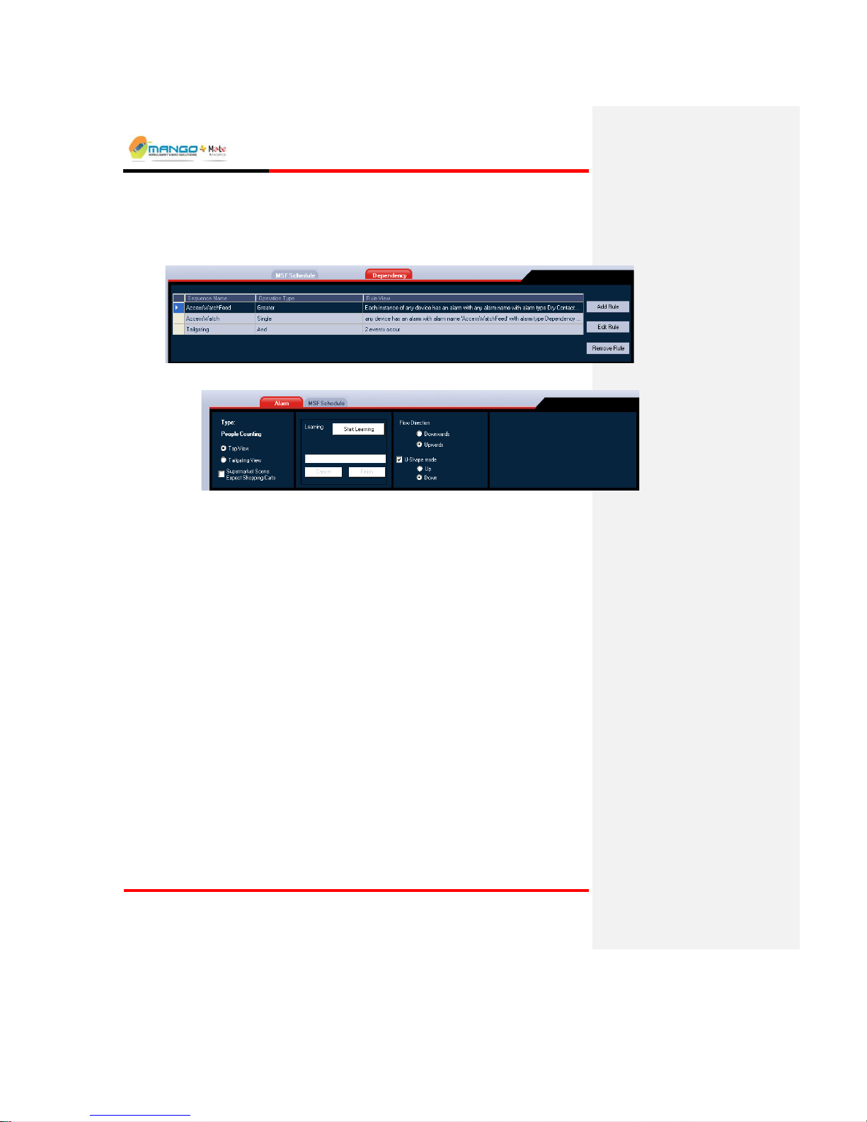
Rules Manager/Device Explorer
V4.5
Page 6-57
6.6.1. Feed 1 MSF
A Dependency MSF, contains a single analytic rule and a three dependency rules.
o Analytic rule: Counting top view
o Dependency Rule 1:
Operand 1: TTL2
Operand 2: Feed 1 analytic result
Function: Greater
Events name: AccessWatchFeed
Parameters
Dwell time: 5 seconds
Send results to manager: false
Page 80
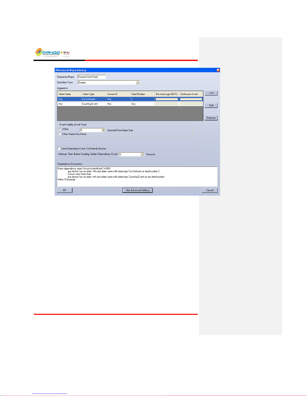
Rules Manager/Device Explorer
V4.5
Page 6-58
o Dependency Rule 2:
Operand 1: AccessWatchFeed
Function: Single
Events name: AccessWatch
Send results to manager: false
Minimal time between two successive alarms: 2 seconds
Page 81

Rules Manager/Device Explorer
V4.5
Page 6-59
o Dependency rule 3:
Operand 1: TTL1
Operand 2: AccessWatch
Function: And
Events name: Tailgating
Parameters
When alarms are active
Send results to manager: true
Page 82

Rules Manager/Device Explorer
V4.5
Page 6-60
6.6.2. Feed 2 MSF
A Dependency MSF, contain a single analytic rule and a single dependency rule.
o Analytic rule: Counting side view
o Dependency rule:
Operand 1: Feed 2 analytic result
Operand 2: TTL2
Function: Greater
Events name: AccessWatchFeed
Parameters
Page 83

Rules Manager/Device Explorer
V4.5
Page 6-61
Dwell time: 5 seconds
Send results to manager: false
Page 84

Page 85
AVCS
V4.5
Page 7-1
7. AVCS
IN THIS SECTION
Launching AVCS ........................................ 7-16-1
AVCS Interface .......................................... 7-26-2
Cortex Player ............................................. 7-36-3
The Alarm Video Clip Server (AVCS) is an optional application for extending the
Video Detection Unit's capabilities, and enabling the saving of a video clip that
displays the pre-alarm and post-alarm event video images with an object overlay.
The video is sent from the Video Detection Unit and stored on the AVCS for
browsing and presentation via the Cortex Player.
The AVCS works only in the Trigger NG 2 mode and not in the 2S, 1S, 1A, or 2A
modes.
7.1. Launching AVCS
Either double-click on the AVCS desktop icon (if AVCS was installed from a
separate CD) or launch the AVC Server application from the Tool menu of
StartUp Application, and then click the AVCS icon which minimizes to the
system tray.
Page 86

AVCS
V4.5
Page 7-2
7.2. AVCS Interface
FIGURE 44:AVCS INTERFACE
7.2.1. Menu Bar
Consists of shortcuts to various functions:
Close: Exit the program.
Tools:
Clear List: Clears the Display.
Cortex Player Application: Launches the Cortex Player.
Configuration:
Cyclic Recording: Records alarms until the maximum alarm capacity is reached and
then starts overwriting the oldest recordings with new ones.
Disk Full Limitation: Records alarms until the maximum alarm capacity is reached
and then stops recording.
Freeze Messages: Stops displaying messages in the Display.
Set Maximum Alarms Capacity: Opens a dialog box where the maximum capacity can
be set.
Change Alarm Directory Path: Opens a dialog box to set a new directory for saving
alarms.
Help:
Page 87
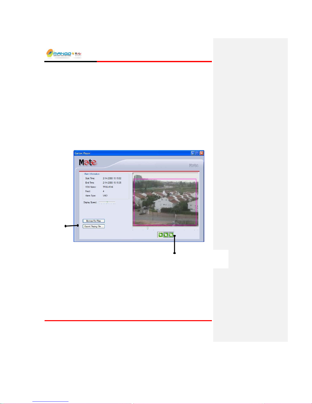
AVCS
V4.5
Page 7-3
Product Help: Launches the online help.
About: Product information.
7.3. Cortex Player
The Cortex Player application is used for viewing saved alarms. Cortex Player
displays a video sequence of the prerecorded alarm with pre and post alarm
images. To launch the Cortex Player Application, select Cortex Player
Application from the Tools menu of AVCS.
The Start Time, End Time, Feed and Alarm Type are displayed in a pane on the
left of the video, with the options to export the clip to a file or to browse for
another file.
FIGURE 45: CORTEX PLAYER
Browse/Export
Options
Play/Stop/Pause
Options
Page 88

Page 89

RTP/RTSP
V4.5
Page 8-1
8. RTP/RTSP VIDEO NODE
You can open an RTP/RTSP video node in QuickTime. If you do not add parameters to the
URI, the default parameters will be used (configurable via the video settings tab in device
explorer).
To open a RTP/RTSP video node in QuickTime:
1. Make sure a video source is properly connected to the first input of your board.
2. Input a URI to your video player.
In QuickTime this is done by choosing Open URL from the File menu or
pressing Ctrl-U on the keyboard:
FIGURE 46: QUICKTIME OPEN URL
The Open URL window appears:
FIGURE 47: URL INPUT DIALOG
3. Type your board’s current IP address.
4. Click OK.
Page 90
RTP/RTSP
V4.5
Page 8-2
8.1. RTSP URI Format
A Uniform Resource Identifiers (URI) is a compact string of characters used to identify or
name a resource on the Internet. The main purpose of this identification is to enable
interaction with representations of the resource over a network, typically the World Wide
Web, using specific protocols. URIs are defined in schemes defining a specific syntax and
associated protocols.
8.2. General Structure
The URI is built of stream specifications. Each stream specification contains a keyword that
identifies the type of the stream (by which stream handlers are registered in the application),
and optionally a list of parameters that modify the default behavior of the stream.
Rtsp://ip.address/keyword[?param1[=value1][¶m2[=value2]…].]/keyword…
A more detailed example of the RTSP URI format is as follows:
rtsp://ip_address/?multicast{¶m1{=val1}{¶m2{=val2}...}}/video_media{?param1{
=val1}{¶m2{=val2}...}}/audio_media{?param1{=val1}{¶m2{=val2}...}}
Note: Curly braces indicate optional parameters
Where:
ip_address is the address of the board.
multicast section is optional if the user wants multicast streaming (otherwise streaming is
regular unicast).
The user can specify a stream of video_media and/or a stream of audio_media.
Video_media can be “mjpeg”, or “mpeg4”.
Audio_media can be “pcma”, “pcmu” for audio. PCMA and PCMU are G.711 A-Law and μ-
Law, respectively.
Page 91

RTP/RTSP
V4.5
Page 8-3
Param, val: A list of parameters separated by ‘&’. Some parameters appear on their own,
others have a value. In that case they will appear as param=value. Except as noted, any
parameter not specified in the URI will take its default value from the Web page settings.
The default values given in the following tables are the initial factory settings. With the
exception of “cam” and “mic”, they may all be changed in the Web menu.
Some examples are:
rtsp://192.168.22.59/cam=1&ngop=10…..
rtsp://192.168.0.127/mpeg4&cam=0&imgsize=4CIF&rcmode=CONSTANT_Q&qinit=4
8.2.1. Mjpeg Mode Example
You can request a stream of mjpeg:
rtsp://192.168.22.59/mjpeg&cam=1&q=70
8.2.2. Multicast Streaming
Request a multicast stream to the specified address, and use ports 6790 for the video
rtsp://192.168.0.123/multicast=1&mcast_addr=224.1.0.3&mcast_port=6790
Page 92

RTP/RTSP
V4.5
Page 8-4
8.3. General Video Parameters
TABLE 1: GENERAL VIDEO PARAMETERS
Parameter
Value
Default
Description
cam
0, 1 0 Camera Number
Imgsize
4CIF, CIF, QCIF
CIF
Image Size
format
1, 2
1
1 = mpeg4
2 = mjpeg
mpeg4, mjpeg
-
mpeg4
Spdecify encoder method
framerate
1 - 25, 30
1
This is the frame rate divisor. Set
it to 1 for full frame rate, 2 for
half frame rate, and so on. The
actual frame rate will be:
PAL 25/n fps
NTSC 29.97/n fps
rcmode
VBR/VBR NON_DROP,
CBR/CBR NON-DROP,
CONSTANT_Q
CBR
NONDROP
Rate Control Mode.
ngop
1 – 200
100
Size of GOP (distance between
keyframes)
cbitrate
10000-4000000
384000
Constant Bitrate: Applicable only
when rcmode = CBR.
Avg_bitrate
10000-4000000
-
Average Bitrate: Applicable only
when rcmode = VBR.
Max_bitrate
10000-4000000
-
Maximal Bitrate: Applicable only
when rcmode = VBR.
Qmax
2 – 31
31
Maximum Quantization:
Applicable only when rcmode =
CBR
Qinit
2 – 31
5
Quality setting for I-Frames:
Relevant for rcmode =
CONSTANT_Q.
mcast_addr
224.0.0.0 to
239.255.255.255
232.255.
42.42
Used to change the default
multicast address.
mcast_port
0 to 65535
8888
Change the default multicast port;
mcast_ttl
1 and up
7
Change the default TTL for
multicast packets.
Page 93
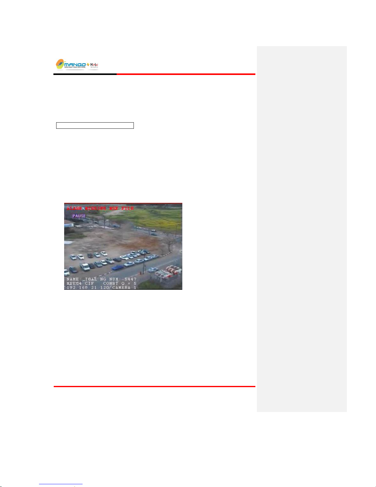
RTP/RTSP
V4.5
Page 8-5
8.4. Video Server OSD
The Video Server OSD is initiated by specifying OSD=1 in the URL command.
rtsp://192.168.21.144/cam=0&osd=1
8.4.1. Opening a Stream with OSD
For the first 10 seconds after a stream is opened, three white lines appear overlaid on the bottom of the
video image. The lines contain the following information:
[Device Name] [Device Number]
[Main encoder characteristics]
[IP] [Camera Name]
Page 94
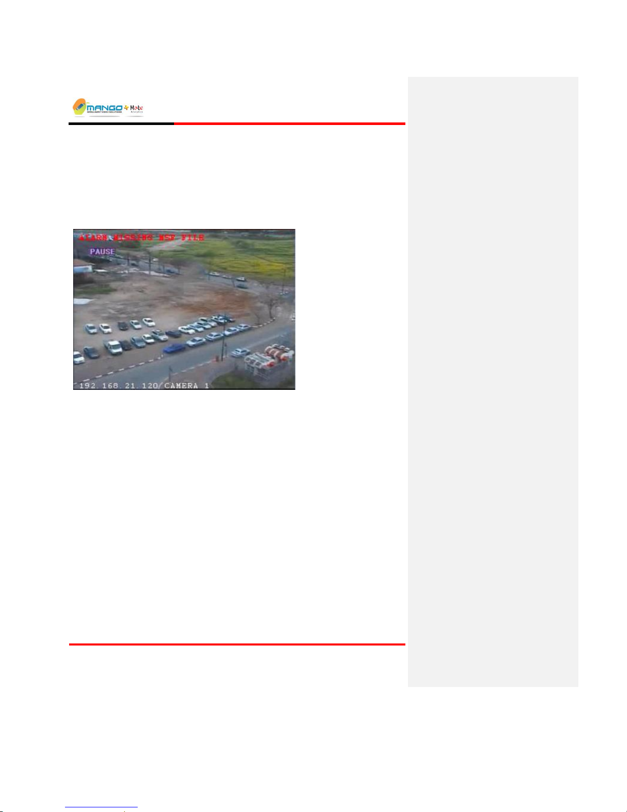
RTP/RTSP
V4.5
Page 8-6
8.4.2. Permanent OSD
After 10 seconds and during ongoing streaming one white line appears overlaid on the bottom of the
video image contain the following information:
[IP] [Camera Name]
The content should be minimal in order not to affect processing.
Page 95

Factory Defaults
V4.5
Page 9-1
9. FACTORY DEFAULTS
The Factory default mode is a software only mechanism to reset the system to the original factory
defaults. The Trigger has three factory default modes:
State 1: Factory default is not active
State 2: Factory default is active for all none networking parameters
State 3: Factory default is active for all parameters (except MAC address)
The Factory Default state machine is determined by System factory default counter.
State 1: Factory default counter equal 0
State 2: Factory default counter equal 2
State 3: Factory default counter equal 3
The following scenario will clear System factory default counter:
Let system run for more then 10 seconds (steady state)
Push reset push button a short push
The following scenario will move System factory default counter into level 2 (state 2):
Push reset push button a short push
Wait until 4 LEDs are set, followed by clearing at least one of them
Push the reset push button and hold it for 4 seconds
Release reset push button.
Wait until 4 LEDs are set, followed by clearing at least one of them
Push the reset push button and hold it for 4 seconds
Release reset push button
Page 96

Page 97
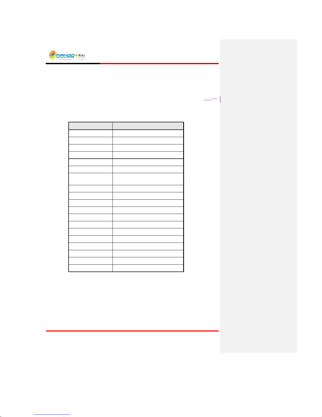
Appendix
V4.5
Page 10-1
10. APPENDIX
IN THIS SECTION
Trigger NG Hardware Specifications ....... 10-19-1
10.1. Trigger NG Hardware Specifications
CHARACTERISTICS
SPECIFICATIONS
Video In
Two (BNC) composite video inputs
Video Out
One (BNC) composite video out
Video Encoding
M-JPEG, MPEG4
Audio In
Dual channel audio (3.5mm Jack)
Audio Out
Dual channel audio (3.5mm Jack)
UART
Two RS232 ports and one RS485 port
Onboard Relays
Two SPDT Relays and two Solid-State
Relays
Relay Contacts
2 pairs (NO-COM-NC) and 2 pairs SSR
Alarm Inputs
Two Optically isolated inputs
Networking
TCP/IP 10/100 Base-T
Power Supply Input
12V DC
Operating Temperature
0-50 C or 32-122F
Storage Temperature
-40C - 85C or -40F - 185F
Operating Humidity
20% - 80% (non condensing)
Storage Humidity
5% - 95% (non condensing)
Power Consumption
Less then 0.5A
Size
190*127*35mm
Weight
0.4kg
USB
1 USB Port
Page 98

Appendix
V4.5
Page 10-2
10.1.1. Audio Specifications
CHARACTERISTICS
SPECIFICATIONS
Analog Output voltage
1.0Vrms, 50 ohm
Output Load Resistance
> 10 Kohm
Analog Input voltage
Maximum 1.0Vrms
Signal to Noise Ration
85 dB
Total Harmonic
Distortions
- 86 dB
10.2. List of WAN Port Numbers and Applications
PORT NUMBER
APPLICATION
1976
AVCS
1977
Counting Metadata
1979
Metadata/Alerter
4808
Cortex Viewer
4809
Rules Manager
4810
Cortex Server
5000
Intellex V3.x
5001
Intellex V4.x
6970
Live Video
1984
Device Explorer
1985
7071
7072
7095
7096
8071
50152
Audio In
50153
Audio Out
Page 99

Index
V4.5
Page 11-1
11. INDEX
A
About this Guide .......................................................... 1-2
Activate Relay ............................................................ 5-19
Activating/Deactivating a Single MSF ....................... 5-22
Activating/Deactivating Multiple MSFs .................... 5-22
Advanced Settings Tab ................................................ 5-7
Alarm Geometry Pane ................................................ 5-18
Alarm Tab .................................................................. 5-19
Alarm Types .............................................................. 5-33
Analog Video Out ........................................................ 5-9
Appendix .................................................................... 10-1
Architecture ........................................................ 2-2, 6-54
Audio Devices ............................................................ 5-12
Audio Specifications .................................................. 10-2
AVC Server ................................................................ 5-13
AVCS ........................................................................... 7-1
AVCS Interface ............................................................ 7-2
C
Camera Naming ......................................................... 5-10
Car Counting .............................................................. 5-51
Classification Tab ...................................................... 5-24
Cortex Installation ........................................................ 3-3
Cortex Player ............................................................... 7-3
Cortex Policy Manager ................................................ 2-3
Cortex Server ............................................................... 2-3
Cortex Viewer .............................................................. 2-4
Creating a Dependency MSF ..................................... 5-44
Creating an MSF ........................................................ 5-21
Current Device Settings ............................................... 5-5
D
Default Interface Type ............................................... 5-14
De-Interlace Filter ...................................................... 5-10
Deleting an MSF ........................................................ 5-22
Device Explorer ........................................................... 5-1
Device Explorer View .................................................. 5-4
Directional Motion Alarm .......................................... 5-38
Display and Editing Options ...................................... 5-29
DVR ........................................................................... 5-15
E
Enable Relay Output for System Event ...................... 5-19
Exporting an MSF ...................................................... 5-23
G
General Settings Tab .................................................... 5-4
Getting Started ............................................................. 4-1
H
Hardware and Operating System Requirements ........... 3-1
I
Ignore Zone Tab ........................................................ 5-28
Image Properties .......................................................... 5-7
Importing an MSF ..................................................... 5-23
In the Package .............................................................. 3-1
Indoor/Outdoor Selection .......................................... 5-21
Initial Use of the Application ....................................... 4-1
Installing .NET Framework ......................................... 3-3
Installing the Cortex Software ..................................... 3-3
Installing the Hardware ................................................ 3-2
Interface Language ...................................................... 4-4
Introduction ................................................................. 1-1
L
Launching AVCS ........................................................ 7-1
Launching Device Explorer ......................................... 5-1
LED Display ................................................................ 3-3
Loitering Alarm ......................................................... 5-39
M
Menu Bar .............................................................. 5-3, 7-2
Metadata Client / Server / Alerter .............................. 5-14
MSF Schedule Tab .................................................... 5-20
N
New Device Settings.................................................... 5-5
O
Object Removal Alarm .............................................. 5-41
Object Sizes Tab ........................................................ 5-24
Object Started Alarm ................................................. 5-37
Optional Settings ....................................................... 5-29
Overview ..................................................................... 2-1
P
Path Detection Alarm ................................................ 5-36
People Counting ........................................................ 5-50
Presence Alarm .......................................................... 5-35
R
Relay / Input .............................................................. 5-11
Renaming an MSF ..................................................... 5-22
ROI Tab for Detection Zone Geometry ..................... 5-24
Rules Manager ............................................................. 2-4
Rules Manager Interface ............................................ 5-17
S
Saving an MSF .......................................................... 5-21
Scene Switch Feature ................................................. 5-30
Scheduler Options ...................................................... 5-20
Sensitivity .................................................................. 5-19
Setting Alarms ........................................................... 5-29
Software Architecture .................................................. 2-3
Speed Alarm .............................................................. 5-40
StartUp Application ..................................................... 4-2
Static Object Alarm ................................................... 5-34
System Setup ............................................................... 3-1
Page 100

Index
V4.5
Page 11-2
T
The Technology ........................................................... 2-2
Tree View ...................................................................5-18
Trigger NG Hardware Specifications .........................10-1
U
Un-Installing the Software ........................................... 3-4
V
Video Analytics Engine ............................................... 2-3
Video Source ............................................................... 5-5
Video Transmission Settings ....................................... 5-8
VMD (Video Motion Detection) Alarm .....................5-33
W
Working with Alarm Geometries ...............................5-23
Working with MSFs ...................................................5-21
Working with Perspective ..........................................5-26
Working without Perspective .....................................5-25
 Loading...