


Instruction Manual
Manfred Weber
Metra Mess- und Frequenztechnik in Radebeul e.K.
Meissner Str. 58 - D-01445 Radebeul
Phone +49-351 836 2191 Fax +49-351 836 2940
Email: Info@MMF.de Internet: www.MMF.de
8 Channel
IEPE
Conditioner
M208B

Manfred Weber
Metra Mess- und Frequenztechnik in Radebeul e.K.
Meissner Str. 58
D-01445 Radebeul
Phone +49-351-836 2191
Fax +49-351-836 2940
Email Info@MMF.de
Internet www.MMF.de
Notice: The current version of this document can be downloaded from
http://www.mmf.de/product_literature.htm
Specifications subject to change without prior notice.
© 2009 Manfred Weber Metra Mess- und Frequenztechnik in Radebeul e.K.
No part of this document may be reproduced without the prior written consent of Metra.
May/ 16

Contents
1. Application............................................................................................................4
2. The Instrument at a Glance....................................................................................4
2.1. Connectors and Controls................................................................................4
2.2. Menu Structure...............................................................................................5
3. What is IEPE?........................................................................................................5
4. Description of the Instrument ...............................................................................7
5. Power Supply.........................................................................................................8
6. Inputs and IEPE Supply.........................................................................................9
7. Outputs..................................................................................................................9
8. Grounding and Avoiding Ground Loops .............................................................10
9. Operation ............................................................................................................10
9.1. Gain Selection..............................................................................................10
9.2. IEPE Indicators............................................................................................10
9.3. Overload Indicators......................................................................................10
10. Filters and Integrators........................................................................................11
10.1. Filters .........................................................................................................11
10.2. Integrators..................................................................................................13
10.3. Replacing Filter Modules ..........................................................................15
10.4. Switching Off the High Pass Filters............................................................16
10.5. Switching the IEPE Supply On or Off........................................................17
10.6. Loading Default Settings............................................................................17
11. Calibration.........................................................................................................17
12. Hardware and Software Version ........................................................................18
13. Technical Data...................................................................................................19
Appendix: Warranty
CE Declaration of Conformity
Thank you for using a vibration instrument from Metra!
1. Application
The 8 Channel IEPE Conditioner M208B was designed for piezoelectric accelerometers, force transducers, pressure transducers and measuring microphones with IEPE
output. The instrument has the following functions:
• Constant current supply of up to eight sensors
• Gain ranges of 0, 20, 40 and 60 dB
2. The Instrument at a Glance
2.1. Connectors and Controls
4
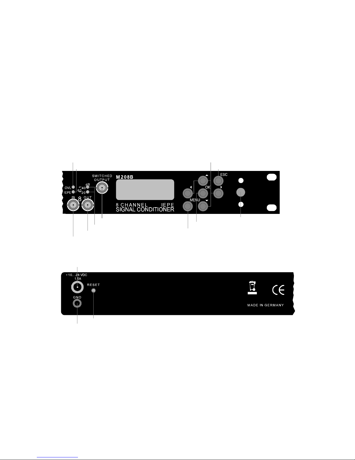
Figure 1: Front and rear panels
Display
LEDs for gain indication
Overload LED
Constant current LED
Output socket (channel 8)
Input socket (channel 8)
Shared output (channels 1 to 8)
Arrow keys for menu navigation
Escape key for leaving menus
OK key for confirming selections
Key for setup menu
Front Panel:
Rear Panel:
Ground socket
Power supply socket
Reset key
POWER
On/Off switch
2.2. Menu Structure
3. What is IEPE?
The M208B is a signal conditioner for sensors with IEPE output. The abbreviation
stands for Integrated Electronics Piezo Electric and is a common industrial standard
for the output of piezoelectric sensors and microphones. Proprietary brand names,
like ICP®, Isotron®, Deltatron®, Piezotron® etc., are also used for the same purpose.
An electronic circuit inside the sensor transforms the high-impedance signal of the
sensing element into an output signal with low impedance, which can more easily be
transmitted and processed.
A distinctive feature of IEPE is the transmission of supply current and measuring
signal via one single wire, so an IEPE transducer is connected via a coaxial cable.
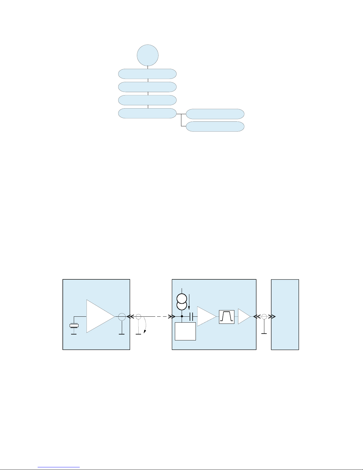
Figure 2 shows the principle circuit of an IEPE measuring chain. To supply the sensor electronics, constant current is used (not to be confused with 4-20 mA current
loops). The constant current is fed into the signal cable by the signal conditioner. A
coupling capacitor keeps the DC components away from the AC signal path.
When constant current is fed into the sensor, a positive DC voltage, called bias voltage, arises at the sensor terminals. Depending on model and manufacturer, the bias
voltage can be in the range from 5 to 14 V. The bias voltage is modulated with the
measuring signal u
sensor
. The sensor output can never become negative. The minimum
output voltage is approximately 1 V, the saturation voltage of the sensor output
stage. The upper voltage limit is determined by the supply voltage of the constant
5
MENU
1/4: Highpass
2/4: IEPE supply
3/4: Load defaults
4/4: Factory setup
1/2: LED test
2/2: Gain calibration
(password protected)
Figure 2: IEPE principle
Integated electronics
U = 24VDC
I
= 4mA
const
s
Q
U
Sensing element
I
const
Constant supply current
U
s
Supply voltage of constant current source
Coaxial cable
> 100 m
IEPE Sensor
M208B
U
bias
+u
sensor
LED
sensor
indication
Filter
Amplifier
Buffer
Readout unit
0 - 60dB
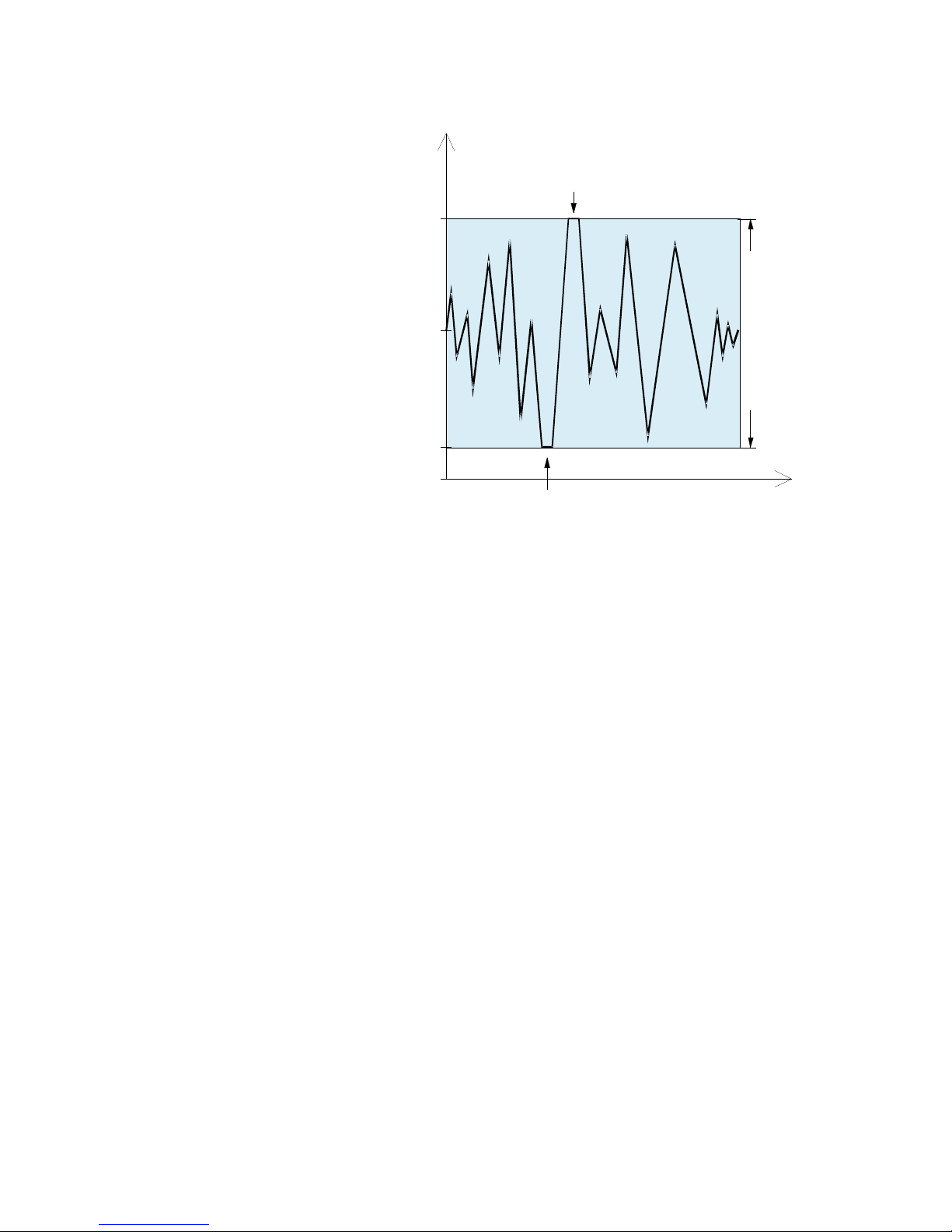
current source, also called compliance voltage. The M208B uses 24 V. Figure 3
shows the dynamic range of an IEPE transducer.
The M208B features a circuit for sensor check. It can detect the following conditions, based on the sensor output voltage:
• No sensor: yellow LED off
• Sensor connected: yellow LED on
The constant current supply can be switched off for each channel (see section 10.5.
on page 17). The sensor detection will then also be deactivated.
6
Figure 3: Dynamic range of IEPE sensors
Max. sensor output =
supply voltage of constant current source
(24 V with M208)
Sensor saturation voltage
(approx. 1 V)
Sensor bias voltage
(see data sheet)
negative overload
0V
positive overload
Sensor dynamic range

4. Description of the Instrument
Figure 4 shows the block diagram of the M208B. The instrument includes eight
identical analog signal paths for amplification and filtering. A micro controller unit
controls the analog part, provides digital interfaces, key control and display functions.
The sensor signals enter the M208B via BNC sockets on the front panel. The IEPE
constant current sources may be switched off individually. The input is followed by
an amplifier stage with selectable gains of 0 or 20 dB. High pass and low pass filters
are designed as plug-in modules. The high pass can be switched off. There are also
single and double integrator modules which may be plugged in instead of the filters.
A selectable attenuator stage is followed by a digital-to-analog converter for gain
calibration. Before the output there is another selectable amplifier stage and a buffer.
Splitting the gain before and after the filters helps to avoid overload at frequencies
in the filter stop band. The output is accessible on the front panel via BNC sockets.
There is a shared output which can be switched to channels 1 to 8.
The M208B is powered from a DC voltage source.
7
Figure 4: Block diagram
I
const
Input 1
BNC
DAC
Output 1
20dB
I
const
Input 8
BNC
DAC 20dB
Channels 1 - 8
Shared
output
MUX
1-8
BNC
Output 8
BNC
BNC
Control Unit
Overload
indication
Micro
Controller
Lowpass
module
Highpass
module
-20/0dB
0/20dB
0/20dB
-20/0dB
0/20dB
0/20dB
1
8
Highpass
module
Lowpass
module
Keypad Display
Micro
Controller
Keypad Display

5. Power Supply
The M208B is powered by an external DC supply voltage between 10 and 28 V.
This could be a supplied mains adapter or a car battery, for example. Current consumption is below 1.5 A. The supply voltage is connected by a circular power connector to DIN 45323. Figure 5 shows the polarity of this socket.
The M208B is protected against false polarization.
There is a fuse inside the instrument. For replacing the fuse, remove the four screws
holding the cover plate and open the case. The location of the fuse holder is shown
in Figure 6. The fuse must be rated 2 A (slow).
Unplug the power supply before replacing the fuse!
Ground your hands before touching electronic components inside!
Use only fuses with the appropriate rating!
8
Figure 5: Polarity of the
supply socket
0 V +10 - 28 V
Figure 6: Location of the fuse holder

6. Inputs and IEPE Supply
The M208B has eight identical measuring channels. Sensors are connected via BNC
sockets marked “IN” on the front panel. The input impedance is approximately
4 MΩ. The input overload limit is ±10 V. The inputs can withstand voltages of up
to ±25 V.
For the operation with IEPE sensors constant current sources must be switched to
the inputs (see 10.5 on page 17). By default the M208B is equipped with 4 mA constant current sources which is a practical value for most applications. For extremely
long sensor cables and high frequencies to be measured, the instrument can also be
equipped with 8 mA sensor supplies. The constant current source module can be replaced by the user. Open the cover plate after removing four screws (see Figure 7).
Unplug the power supply before replacing the module!
Ground your hands before touching electronic components inside!
7. Outputs
The eight outputs are accessible via BNC sockets (“OUT”) on the front panel.
The outputs are short-circuit-proof. Their output impedance is 100 Ω.
In addition to the channel outputs there is a shared output which can be connected to
one of the channels. It is accessible via the BNC socket “SWITCHED OUTPUT” on
the front.
The shared output is always connect to the channel which is flashing in the gain
menu (see section 9.1). You may change the channel by pressing the ◄ ►keys.
9
Figure 7: Location of the constant current source module
Display

8. Grounding and Avoiding Ground Loops
All inputs and outputs are referred to the same ground potential. Ground is also
available at the socket (“GND”) on the rear panel.
The negative supply Terminal (-) is also connected to ground.
To prevent ground loops it is recommended that additional connections are not made
between the sensor cases via the test object. This can be avoided by using sensors
with isolated base or isolating pads which are available as accessory parts.
9. Operation
9.1. Gain Selection
The instrument has four gain ranges of 0, 20, 40 and 60 dB (1, 10, 100 and 1000),
which may be set for each channel individually.
After switching it on, the M208B displays the gain menu (Figure 8).
The selected gain ranges are shown over the respective channel numbers. The flashing value can be changed by the ▲▼ keys. You may select between 0, 20, 40 and
60 dB. Change to another channel by ◄ ►. The active gains are also indicated by
the LEDs over the output sockets:
0 dB: LEDs off
20 dB: orange LED (“20”)
40 dB: green LED (“40”)
60 dB: orange and green LED
The gain settings remain stored when you disconnect the M208B from power.
Note: The flashing channel in the gain menu is also the channel connected to the
shared output (see section 7).
9.2. IEPE Indicators
The yellow “IEPE” LED of an amplifier channel will light up when you connect a
sensor to its input provided that the IEPE supply was switched on.
IEPE constant current indication is based on the measurement of the sensor bias
voltage. If this voltage drops below 20 V the LED lights up.
9.3. Overload Indicators
Each channel has a red overload LED. The signal path is monitored for overload
condition at the sensor and at the amplifier output to make sure that signal components which do not pass the filter but overload the input stage are properly indicated.
The threshold for the overload indicators is 10 V (peak). At this magnitude the signal is still undistorted.
10
Figure 8: Gain selection

Reduce the gain range when the overload LED starts flashing.
Please note that the dynamic range of most IEPE transducers is less than ±10 V so
that in the 0 dB range the signal may become clipped even if no overload is indicated.
10. Filters and Integrators
10.1. Filters
The M208B has replaceable high pass and low pass filter modules. The following
frequencies are available:
High pass filters: Low pass filters:
3 dB frequency limit Model 3 dB frequency limit Model
3 Hz FB3-3Hz 0.1 kHz FB2-0.1kHz
5 Hz FB3-5Hz 0.3 kHz FB2-0.3kHz
10 Hz FB3-10Hz 0.5 kHz FB2-0.5kHz
30 Hz FB3-30Hz 1 kHz FB2-1kHz
50 Hz FB3-50Hz 3 kHz FB2-3kHz
100 Hz FB3-100Hz 5 kHz FB2-5kHz
300 Hz FB3-300Hz 10 kHz FB2-10kHz
500 Hz FB3-500Hz 30 kHz FB2-30kHz
1000 Hz FB3-1000Hz 50 kHz FB2-50kHz
100 kHz FB2-100kHz*
* With the low pass FB2-100kHz at 60 dB gain and frequencies over 50 kHz the
output peak voltage should not exceed ±3V to avoid distortion.
The high pass modules are second order Butterworth filters. The low pass modules
are fourth order Butterworth filters.
The following diagrams show the frequency and phase response curves of the high
pass and low pass filters.
11

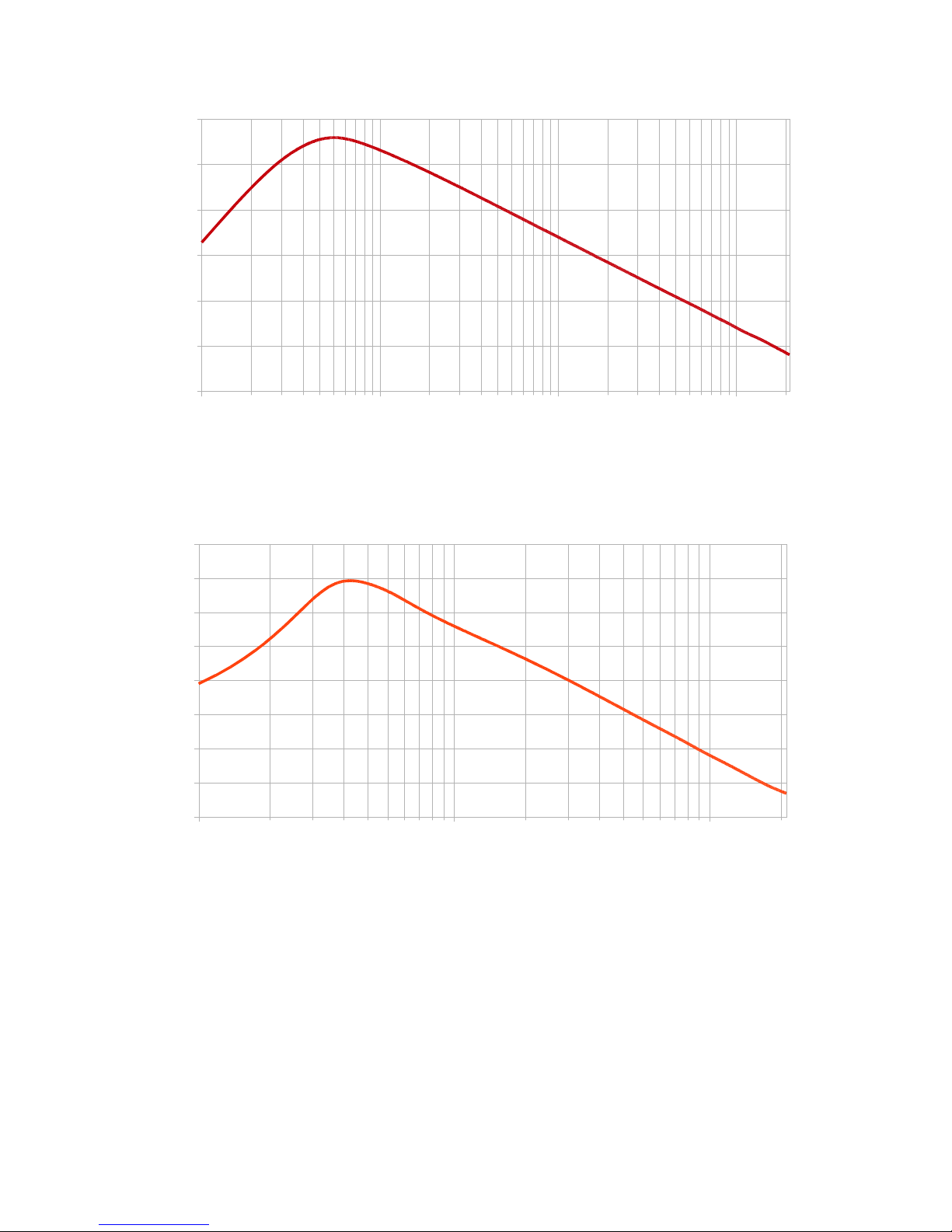
Figure 9: Frequency response of M208B with different high pass filters FB3-...
Figure 10: Frequency response of M208B with different low pass filters FB2-...
12
10
100 1000 10000 100000 1000000
-45
-40
-35
-30
-25
-20
-15
-10
-5
0
FB2-0,1
FB2-0,3
FB2-0,5
FB2-1
FB2-3
FB2-5
FB2-10
FB2-30
FB2-50
FB2-100
f [Hz]
A [dB]
0,01 0,1 1 10 100 1000 10000
-25
-20
-15
-10
-5
0
HP off
FB3-3
FB3-5
FB3-10
FB3-30
FB3-50
FB3-100
FB3-300
FB3-500
FB3-1000
f [Hz]
A [dB]

Figure 11: Phase response of M208B with different high pass filters FB3-...
Figure 12: Phase response of M208B with different low pass filters FB2-...
10.2. Integrators
Integrators are useful to calculate vibration velocity or displacement from an acceleration input.
Single or double integrator modules can be plugged in instead of filters. Mixed filter
operation is also allowed.
The single integrator FBV includes a second order 3 Hz high pass filter.
The double integrator FBD includes a second order 5 Hz high pass filter.
Figures 13 and 14 show the frequency response curves of the integrators.
13
0,1
1 10 100 1000 10000
0
20
40
60
80
100
120
140
160
180
HP aus
FB3-3Hz
FB3-5Hz
FB3-10Hz
FB3-30Hz
FB3-50Hz
FB3-100Hz
FB3-300Hz
FB3-500Hz
FB3-1000Hz
f [Hz]
Phase [°]
10
100 1000 10000 100000 1000000
-180
-160
-140
-120
-100
-80
-60
-40
-20
0
FB2-0,1
FB2-0,3
FB2-0,5
FB2-1
FB2-3
FB2-5
FB2-10
FB2-30
FB2-50
FB2-100kHz
f [Hz]
Phase [°]
The following explanation is given to understand the relationship between the measured mechanical quantity and the integrated output of the M208B with an accelerometer:
The calculations show how the M208B output u
out
corresponds to the three vibration quantities. The selected gain range of the M208B is G (1, 10, 100 or 1000) and
the accelerometer sensitivity (see transducer data sheet) is Bua.
14
Figure 13: Frequency response of the M208B with the single integrator FBV
1,00 10,00 100,00 1000,00
-50
-40
-30
-20
-10
0
10
f [Hz]
A [dB]
Figure 14: Frequency response of the M208B with the double integrator FBD
1,00 10,00 100,00
-50
-40
-30
-20
-10
0
10
20
30
f [Hz]
A [dB]

Vibration acceleration a (without integration):
a=
u
out
G⋅B
ua
(a in m/s²; u
out
in mV; B
ua
in mV/ms-2)
Vibration velocity v (single integration):
v=
u
out
G⋅B
ua
⋅10 s
(v in mm/s; u
out
in mV; B
ua
in mV/ms-2; s = seconds)
Vibration displacement d (double integration):
d =
u
out
G⋅B
ua
⋅100 s
2
(d in µm; u
out
in mV; B
ua
in mV/ms-2; s = seconds)
Example:
Vibration velocity is measured using an accelerometer with a sensitivity of Bqa= 5 mV/ms-2.
The M208B is operated in the range G = 100. Its output voltage is 300 mV
rms
. What is the
corresponding vibration velocity?
Solution:
v=
300 mV
100⋅5mV / ms
− 2
⋅10 s=6 mm / s
eff
When a direct connection between the output voltage of the M208B and the measured physical quantity should be desired (for example “1 mV corresponds to
1 mm/s”), you may may normalize the M208B output in the measuring equipment
connected to its output or in the software.
The frequency range is limited to approximately 6 to 2000 Hz for single integration
and 6 to 200 Hz for double integration. At the upper end of the frequency range only
a poor signal-to-noise ratio can be achieved. This is the consequence of the frequency characteristic of electronic integrators.
It is not recommended to switch off the high pass function (see section 10.4) if
integrator modules are used. The high pass filters inside the integrator modules
have been designed in order to suppress low frequency noise which would appear at the amplifier output.
10.3. Replacing Filter Modules
For replacing filters or integrators, remove the four screws of the cover plate and
open the case.
Unplug the power supply before replacing filters!
Ground your hands before touching electronic components inside!
Figure 15 shows the filter and integrator modules. Each channel has a high pass and
a low pass module. Instead of the high pass and a low pass module an integrator
module can be inserted. Pull out the modules carefully without bending their pins.
15

When inserting the filter or integrator, make sure that the “Pin 1” mark (▼) faces to
the correct side.
For proper function of the M208B it is necessary that all filters or integrators are inserted.
10.4. Switching Off the High Pass Filters
The high pass filters can be switched off separately for each channel. The M208B
will then work with its lower frequency limit of approximately 0.1 Hz. Press the
MENU key and select “1/4: Highpass”. Use the keys ▲▼◄ ► to switch off (○) or
activate (●) the high pass filter for the respective channel. Confirm with OK or press
ESC to quit without changes.
Notice: When the high pass filter is switched off, low frequency noise from the
sensor electronics and the constant current source may pass the signal path. It
may appear as a fluctuating voltage at the amplifier output.
It is not recommended to switch off the high pass function if integrator mod-
ules are used. The high pass filters inside the integrator modules have been de-
16
Figure 15: Location of the filter and integrator modules
Figure 16: Switching high pass filters
on or off

signed in order to suppress low frequency noise which would appear at the amplifier output.
10.5. Switching the IEPE Supply On or Off
IEPE transducers need a constant current supply for operation (compare section 3 on
page 5). For measurements with other sensor types or for using the M208B as AC
amplifier, it may be necessary to switch off the constant current sources. This can be
done for each channel separately. Press the MENU key and open the menu “2/4:
IEPE supply”.
Use the keys ▲▼◄ ► to disable (○) or enable (●) the constant current source of
the respective channel. Confirm with OK or press ESC to quit without changes.
When the IEPE supply is switched off, the M208B works as voltage amplifier with
the gains 0 / 20 / 40 / 60 dB.
It is recommended that the IEPE supply of unused channels be kept switched
on in order to terminate the inputs. Otherwise electromagnetic interference via
the unterminated inputs could induce noise in other channels.
10.6. Loading Default Settings
The M208B can be reset to its factory default settings in the menu “3/4: Load defaults”. The following settings will be changed:
• Gain for all channels 0 dB
• All high pass filters switched off
• All IEPE constant current sources switched off
Calibration data is not changed.
11. Calibration
This section is intended only for users with sufficient experience in the field of the
measurement of low AC signals and with precise measuring equipment of traceable
accuracy.
We recommend a factory re-calibration at Metra after two years when the M208B
was used under normal environmental conditions.
The M208B can be calibrated without opening the case. There are no adjustment
points inside.
Click the MENU key to open the menu „4/4: Factory setup“. This menu is password protected to avoid unwanted alteration. Enter the following password: “1410”.
After opening the calibration menu the IEPE constant current sources and the high
pass filters will be automatically switched off.
17
Figure 17: Switching the IEPE supply
on or off

In some cases it may be desired to reset all calibration values to 0.0 % before calibration. This can be done by holding the MENU key while pushing the RESET key
on the rear panel. Erasing the calibration values must be confirmed by OK.
Calibration is performed by feeding a sine-wave generator signal into all eight in puts simultaneously. No inputs must be left unterminated. Use “T” couplers and
short BNC cables to interconnect the inputs. The generator frequency shall be 80 Hz
and the RMS value 5.000, 50.00, 500.0 or 5000 mV, depending on the gain range to
be calibrated. In addition to the generator, a calibrated RMS voltmeter should be
connected to the inputs.
The amplifier output voltage of all channels is measured at the connector “
SWITCHED OUTPUT” with a second calibrated RMS voltmeter. The signal quality
at the outputs should also be monitored with an oscilloscope.
Select the channel to be calibrated (“Channel No.:”, 1 to 8) and the gain range
(“Gain range”, 0/20/40/60 dB) by the ▲▼keys. Feed in the generator signal according to the display of the M208B, for example 50.00 mV in the gain range 40 dB.
The M208B will display the previously entered calibration value in percent, for example “-0.3%”. Change this value by the ▲▼ keys in steps of 0.1 % until the output voltage is exactly 5000 mV (RMS). Limits for calibration are ±2 %. Press OK to
save your adjustment and to switch to the next channel or gain range.
12. Hardware and Software Version
The version number of your M208B is displayed for two seconds after switching on
power.
The format of the version number is xxx.yyy with the hardware version xxx and the
firmware version yyy. The line beneath shows the firmware upload date.
18
Figure 18: Version number

13. Technical Data
Inputs
8 voltage inputs; single-ended; R
I
= 4 M
AC coupled; IEPE compatible; BNC sockets
± 10 V without clipping at 0 dB gain
± 25 V peak input voltage
IEPE sensor supply 3.8 to 5.6 mA constant current; switchable
compliance voltage > 22 V
constant current indication by LED
Suitable sensors IEPE compatible accelerometers, force transducers,
pressure transducers and measuring microphones
Gains 0 / 20 / 40 / 60 dB
Gain accuracy < 0.3 % of nominal value at T = 15 to 25 °C;
Ua = 1 to 5 V (RMS); f = 80 Hz; high pass off; low pass 100 kHz
Noise (wide band)
Noise densities
< 10 mV
RMS
(0.1 Hz - 30 kHz)
1 Hz: 600 µV/√Hz
10 Hz: 150 µV/√Hz
100 Hz: 60 µV/√Hz
1000 Hz: 60 µV/√Hz
Cross-talk attenuation > 80 dB
Frequency range 0.1 to 100 000 Hz (-3 dB);
max. ± 3 V output at 60 dB and > 50 kHz
High pass filters Plug-in modules: 3 / 5 / 10 / 30 / 50 / 100 / 300 / 500 / 1000 Hz
frequency tolerance ± 10%; 2nd order Butterworth filter
Low pass filters Plug-in modules: 0.1 / 0.3 / 0.5 / 1 / 3 / 5 / 10 / 30 / 50 / 100 kHz
frequency tolerance ± 10%; 4th order Butterworth filter
Integrators Single integrator module FBV; double integrator module FBD
Outputs 8 buffered channel outputs; ± 10 V;100 Ω, BNC
1 buffered shared output; ± 10 V;100 Ω; BNC
output offset voltage: < 3 mV
Overload indication at sensor input and at at output by LEDs; threshold ± 10 V
Warm-up time 5 min
Power supply 10 to 28 V DC; < 1.5 A; DIN 45323 power connector
Operating temperature
range
-10 to 50 °C
Dimensions 483 mm (19”) x 44 mm (1 HU) x 124 mm
Weight 1.7 kg
19

Limited Warranty
Metra warrants for a period of
24 months
that its products will be free from defects in material or workmanship
and shall conform to the specifications current at the time of shipment.
The warranty period starts with the date of invoice.
The customer must provide the dated bill of sale as evidence.
The warranty period ends after 24 months.
Repairs do not extend the warranty period.
This limited warranty covers only defects which arise as a result
of normal use according to the instruction manual.
Metra’s responsibility under this warranty does not apply to any
improper or inadequate maintenance or modification
and operation outside the product’s specifications.
Shipment to Metra will be paid by the customer.
The repaired or replaced product will be sent back at Metra’s expense.
Declaration of Conformity
According to EMC Directive 2014/30/EC
Product: 8 Channel IEPE Conditioner
Type: M208B (from Ser. no. 160000)
It is hereby certified that the above mentioned product complies
with the demands pursuant to the following standards:
DIN EN 61326-1: 2013
DIN EN 61010-1: 2011
DIN 45669-1: 2010
The producer is responsible for this declaration
Metra Mess- und Frequenztechnik
in Radebeul e.K.
Meißner Str. 58, D-01445 Radebeul
declared by
Michael Weber
Radebeul, April 22, 2016
 Loading...