


027/12
VALID FROM: 01.10.2013
INSTALLATION INSTRUCTIONS
MULTI COMPARTMENT SMOKE
EXTRACTION DAMPER

2
Content
General information
................................................................................................... 3
Assembly information
................................................................................................ 3
Installation opening.......................................................................................... 4
Statement of installation................................................................................... 4
The Blades Overlaps........................................................................................ 8
The Flanges....................................................................................................... 9
Connection Diagrams
................................................................................................... 9
Service, assembly and revisions
.............................................................................. 11
Dimensions
................................................................................................................... 11
Material
.......................................................................................................................... 12
3
Smoke extract dampers - multi are shutters in the smoke exhaust piping systems. The dampers are
designed to remove heat and combustible products (e.g. smoke) from fire compartments. The
damper blade is controlled by actuating mechanism. The dampers are designed for using in fire
compartments that can be connected to the smoke exhaust ducts (tested according to EN 1366-8)
or they can be installed in or on the construction of the fire compartment.
Dampers are classified according to EN 13501-4.
General information
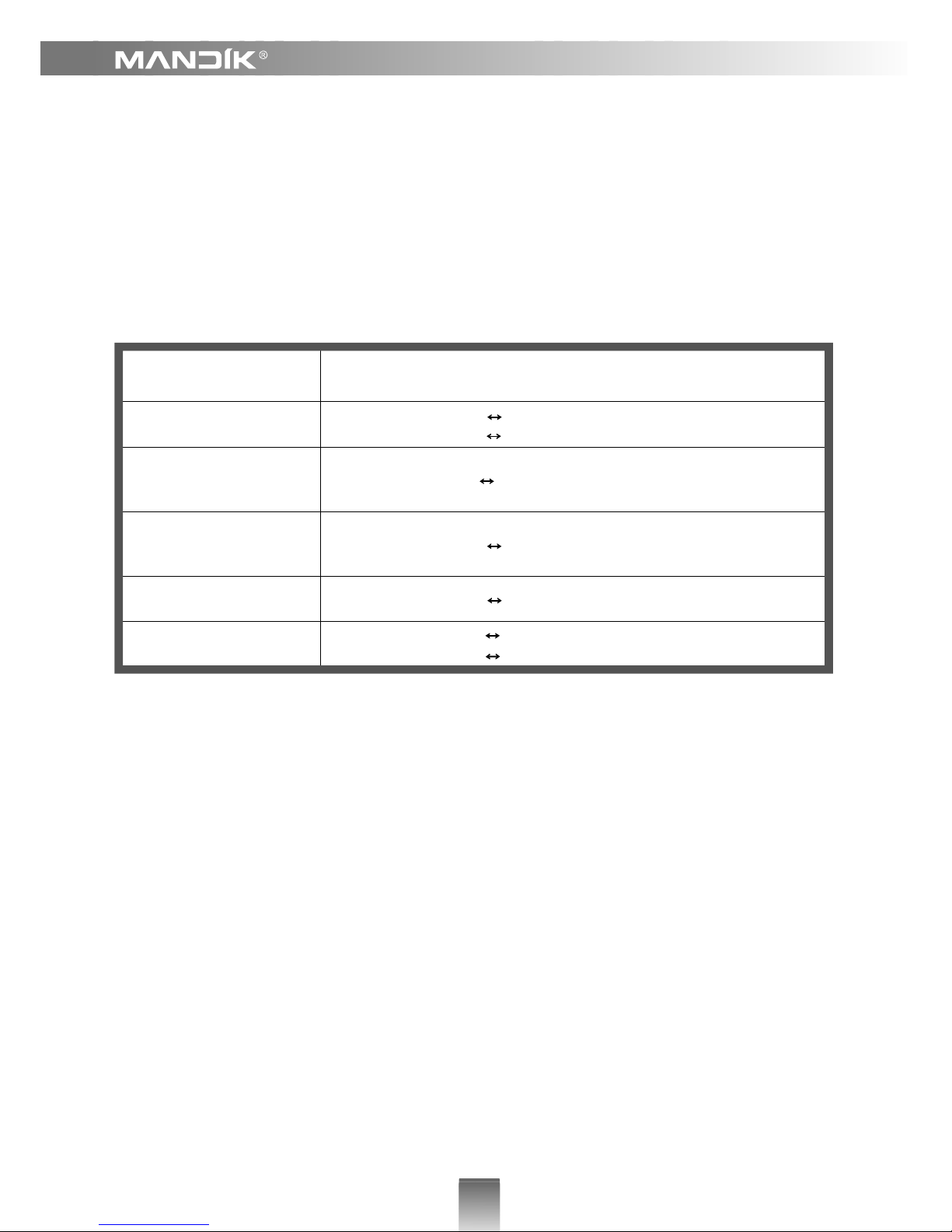
Classification of Dampers
Supporting
Construction
Classification
Horizontal duct system
EI 120 (h
od
- i o) S1000C
10000
HOT 400/30Mamulti
EI 120 (h
od
- i o) S1000C
10000
HOT 400/30AAmulti
Porous concrete ceiling
construction,
thickness 150 mm
EI 90 (h
ow
- i o) S1000C
10000
HOT 400/30AAmulti
Porous concrete wall
construction,
thickness 100 mm
EI 120 (v
ew
- i o) S1000C
10000
HOT 400/30AAmulti
Gypsum wall, thickness
100 mm
EI 120 (v
ew
- i o) S1000C
10000
HOT 400/30AAmulti
Vertical duct system
EI 120 (v
ed
- i o) S1000C
10000
HOT 400/30MAmulti
EI 120 (v
ed
- i o) S1000C
10000
HOT 400/30AAmulti
Assembly information
1. During installation the damper blade must be in position “CLOSED”. The damper body should
not be deformed in the course of bricking in. Once the damper built in, its blade should not grind
on the damper body during opening or closing.
3. During installation the control mechanism must be protect against damaged and pollution.
2.
The installation of more dampers into the fire separating construction must meet the following
requirements:
- the minimum distance between two dampers has to be 200 mm;
- the minimum distance between damper and construction (ceiling / wall) has to be 75 mm;
In the event of fire the Smoke and Fire Ventilation System opens the damper in the affected section
which removes combustion products and heat from this section.
Fire dampers are suitable for installation in arbitrary position (axle of the blade as horizontal or
vertical). The Air Flow (smoke) must be directed from the control device side (see arrow on the
damper body).
Dampers are designed for macroclimatic areas with mild climate according to EN 60 721-3-3 zm.A2.
4
5. Statement of installations
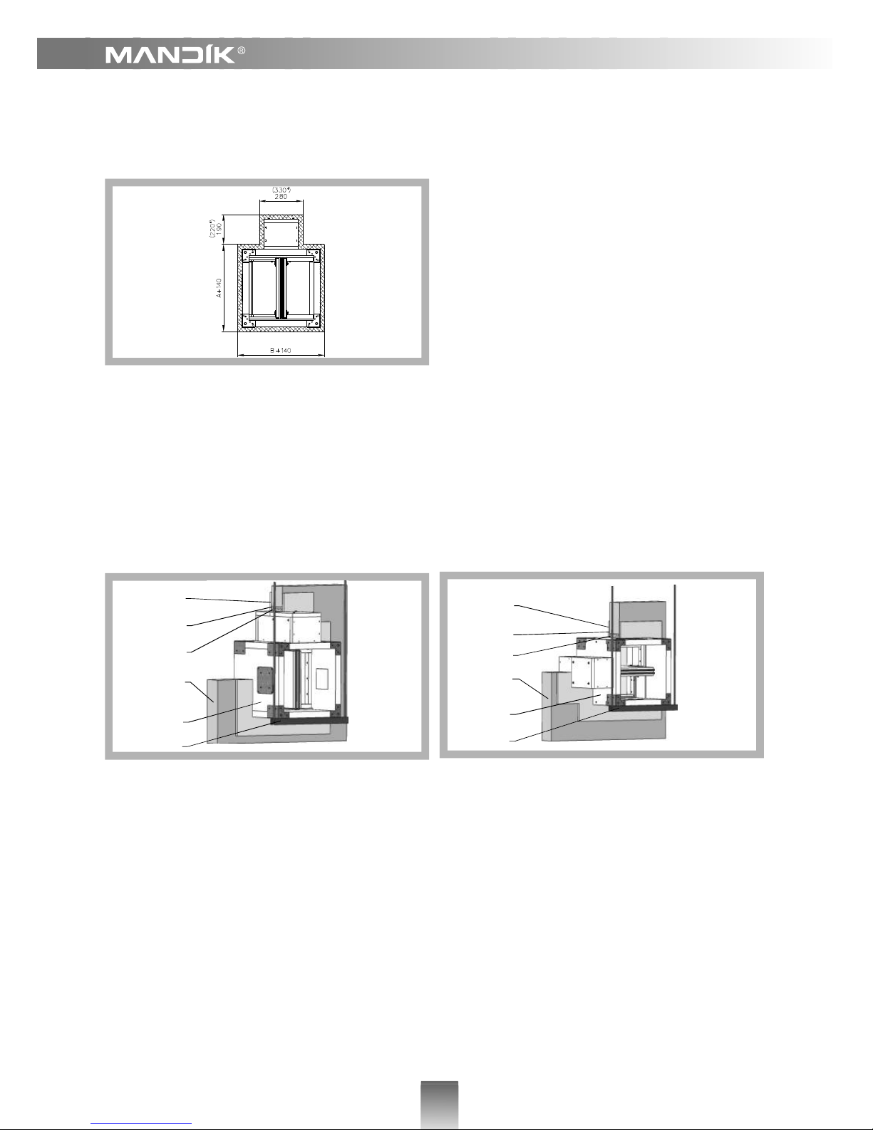
4. Installation opening
NOTICE
*Dime
nsions for damper with actuating
mechanism InMax 50.75
Recommended installation opening
NOTICE
The actuating mechanism cover must be removable after the installation.
Installation in the solid wall (ceiling) construction of fire compartment
Installation in the solid wall construction of fire
compartment. Damper blade is in horizontal position.
Installation in the solid wall construction of fire
compartment. Damper blade is in vertical position.
2
5
4
3
1
6
2
5
4
3
1
6
Position
1 Damper SEDM
2 Solid wall construction
3 Mineral stone wool, density 140 kg/m
3
4 Fire protection mastic, thickness 1 mm
5 Cement lime plate, thickness 15 mm, density 870 kg/m
3
6 Hinges

5
Position
1 Damper SEDM
2 Solid ceiling construction
3 Mineral stone wool, density 140 kg/m
3
4 Fire protection mastic, thickness 1 mm
5 Cement lime plate, thickness 15 mm, density 870 kg/m
3
6 Hinges
2
5
4
3
1
6
Installation in the solid wall construction of fire
compartment
NOTICE
The actuating mechanism cover must be
removable after installation.
Installation in the gypsum wall construction of fire compartment
Position
1 Damper SEDM
2 Gypsum construction
3 Mineral stone wool, density 140 kg/m
3
4 Fire protection mastic, thickness 1 mm
5 Cement lime plate, thickness 15 mm, density 870 kg/m
3
6 Hinges
Installation on gypsum wall construction of fire
compartment
2
5
4
3
1
6
NOTICE
The actuating mechanism cover must be
removable after installation.

6
Installation on the solid wall (ceiling wall) construction
Position
1 Damper SEDM
2 Solid wall construction
3 Ceramic paper
4 Hinges
2
4
1
3
Installation on the solid wall construction of fire compartment Damper blade is in horizontal position.
Installation on the solid wall construction of fire compartment. Damper blade is in vertical position.
2
4
1
3
Position
1 Damper SEDM
2 Solid wall construction
3 Ceramic paper
4 Hinges

7
Installation on the solid ceiling construction of fire compartment - suspension
4
5
1
2
3
Pozice:
1 Damper SEDM
2 Solid ceiling construction
3 Ceramic paper
4 Hinges
5 Cement lime plate
Installation on the solid ceiling construction of fire compartment - mounting from top
1
4
2
3
Position
1 Damper SEDM
2 Solid ceiling construction
3 Ceramic paper
4 Hinges

8
6. Damper assembly procedures must be done so as all load transfer from the fire separating
constructions to the damper body is absolutely excluded. Back-to-back air - conditioning piping
must be hung or supported so as all load transfer from the back-to-back piping to the damper is
absolutely excluded.
Installation in smoke exhaust ducts
Installation in vertical smoke exhaust duct
Installation in horizontal smoke
exhaust duct
7. Flanges
NOTICE
Flanges for square fire dampers are 30 mm
wide with oval hole.
Flanges for SEDM

9
Connection Diagrams
Actuating mechanism BELIMO BLE 24(-ST)
8. Blade overlaps
The overlaps of SEDM
The overlaps of SEDM with flange
AxB
a c e f
Ax180
- - - -
Ax200
- - - -
Ax225
- - - -
Ax250
- - -
Ax280
- - -
Ax300
- - -
Ax315
- - -
Ax355
- 6,5 - -
Ax400
- 29 - -
Ax450
- 54 - 4
Ax500
- 79 - 29
Ax550
104 54
Ax560
- 109 - 59
Ax600
- 129 - 79
Ax630
- 144 - 94
Ax650
- 154 - 104
Ax700
11 179 - 129
Ax710
16 184 - 134
Ax750
36 204 - 154
Ax800
61 229 11 179
Ax900
111 279 61 229
Ax1000
161 329 111 279
NOTICE
The blade of dampers without flange exceeds body of fire damper by the values “a” and “c”.
The blade of dampers with flange exceeds body of fire damper by the values “e” and “f”. There has
to be enough space in dust or installation shaft for blade rotation.

10
Actuating mechanism BELIMO BE 230-12
Actuating mechanism BELIMO BE 24-12(-ST)
Actuating mechanism BELIMO BLE 230

11
5. The adjustment of the blade can be done by connecting the power supply to the actuator (or by
the signal from the Smoke and Fire Ventilation system). The blade is adjusted to the position
"OPENED" and then back to position "CLOSED".
6. Manual operation
Any position of the damper blade can be manually set by using a special key. The functionality
of the damper can be then easily tested.
1.
Assembly, maintenance and damper check can be done
only by qualified persons, i.e.
“AUTHORIZED PERSONS” that have been trained by the manufacturer.
2. All effective safety standards and directives must be observed during fire damper assembly.
3. Before entering the dampers into operation after assembly and after sequential revisions,
checks and functionality tests of all designs including operation of the electrical components
must be done. After entering into operation, these revisions must be done according to
requirement set by national regulations.
Assembly, service and revisions
Visual inspection of proper fire damper integration, inside fire damper area, fire damper blade,
contact surfaces and silicon sealing.
4. After fire damper assembly the following checks must be carried out:
Inspection hole disassembly: release the covering lid by removing the four screws in the
corners of the inspection hole. Then remove lid from its original position.
Actuating mechanism SCHISCHEK InMax 50.75-S

12
1. Damper and blades are made of fire resistant asbestos free boards made of mineral fibres.
Material
2. Fasteners is galvanized.
Dimensions
Damper SEDM
Damper SEDM with flanges
NOTICE
*Dimensions for damper with actuating mechanism InMax 50.75
MANDÍK, a.s.
Dobříšská 550
26724 Hostomice
Czech Republic
Tel.: +420 311 706 706
Fax: +420 311 584 810, 311 584 382
e-mail: mandik@mandik.cz
www.mandik.cz
All rights reserved by Manufacturer. Changes to the product can be applied.
The current product information are available on www.mandik.cz
 Loading...