

Mandik MSD Square, MSD Round User Manual

TPM 109/15
These technical specifications state a row of manufactured sizes and models of multi smoke dampers (further only
dampers) MSD. It is valid for production, designing, ordering, delivery, maintenance and operation.
I. CONTENT
II. GENERAL INFORMATION 2
1. Description.........................................................................................................................
2. Design................................................................................................................................
3. Communication and control devices.................................................................................... 8
4. Dimensions, weights........................................................................................................... 9
5. Placement and Assembly.................................................................................................... 24
III. TECHNICAL DATA 30
6. Pressure loss...................................................................................................................... 30
7. Coefficient of local pressure loss......................................................................................... 31
8. Noise data..............….…………………………………......................................................... 32
IV. MATERIAL, FINISHING 34
9. Material............................................................................................................................. 34
V. INSPECTION, TESTING 34
10. Inspection, testing............................................................................................................. 34
VI. TRANSPORTATION AND STORAGE 34
11. Logistic terms.................................................................................................................... 34
2
3
VII. ASSEMBLY, ATTENDANCE, MAINTENANCE AND REVISIONS 34
12. Assembly.......................................................................................................................... 34
13. Entry into service and revisions......................................................................................... 35
14. Spare parts....................................................................................................................... 35
VIII. PRODUCT DATA 36
15. Ordering key...................….…..........................................................................................
36
IX. ORDERING INFORMATION 37
16. Ordering key.....................................................................................................................
37
1
TPM 109/15
II. GENERAL INFORMATION
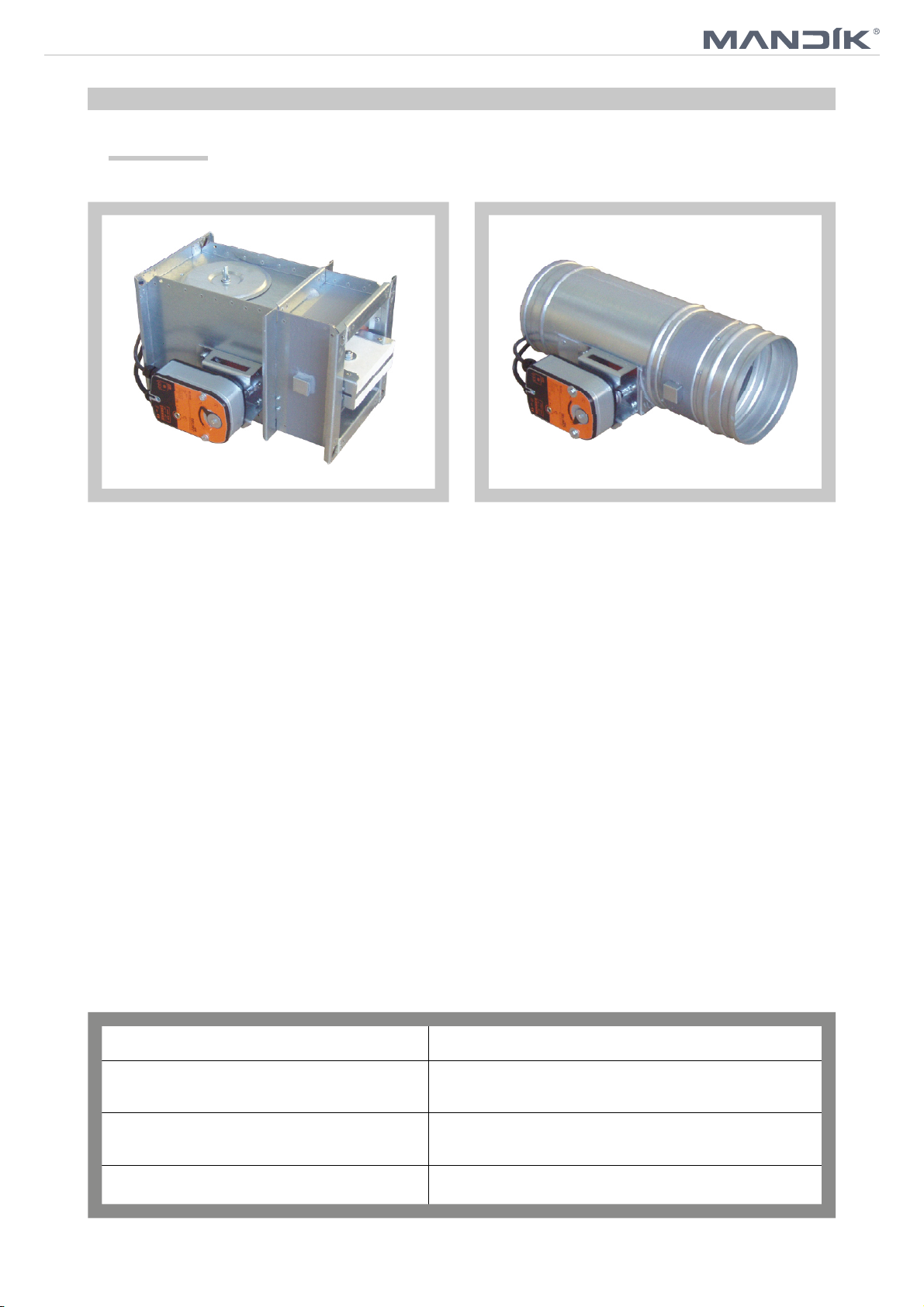
1. Description
Fig. 1 Damper MSD - square Fig. 2 Damper MSD - round
1.1. Multi smoke dampers are shutters in the smoke exhaust duct systems. The dampers are
designed to remove heat and combustible products (e.g. smoke) from effected fire compartments.
In the event of fire the Smoke and Fire ventilation system opens the damper in the affected
section and removes combustion products and heat from this section.
The damper blade is controlled by electrical actuating mechanism.
Dampers are fire resistant and are intended for systems with automatic activation.
Dampers can be installed in construction of the fire compartment.
1.2. Damper characteristics
• CE certified acc. to EN 12101-8
• Tested in accordance with EN 1366-10
• Classified acc. to EN 13501-4+A1
• Fire resistance according Tab. 1.2.1
• External casing leakage class min. C acc. to EN 1751
• Internal leakage: round dampers - class min. 2, diameters from 560 mm to 630 mm min.
class 3 acc. to EN 1751
square dampers - class min. 2, for max. dimension 1500 x 800 mm min.
class 3 acc. to EN 1751
• Cycling test in class C 10000 acc. to EN 15650 (design MSD-W is tested without load)
• ES Certificate of conformity No. 1391-CPD-2015/0057 for MSD
• ES Certificate of conformity No. 1391-CPD-2015/0058 for MSD-W
• Declaration of Perfomance No. CDM/MSD/001/15
Tab. 1.2.1. Classification of Dampers
Supporting Construction Classification
Porous concrete ceiling construction,
thickness 150 mm
Porous concrete wall construction,
thickness 100 mm
EI 120 (how - i↔o) S1500C
EI 120 (vew - i↔o) S1500C
10000
10000
AAmulti
AAmulti
Gypsum wall, thickness 125 mm
EI 120 (v
- i↔o) S1500C
ew
10000
AAmulti
2
TPM 109/15
1.3. Working conditions
Exact damper function is provided under the following conditions:
a) maximum air velocity 15 m.s
-1
b) underpressure max. -1500 Pa or overpressure max. 500 Pa.
Dampers can be installed in arbitrary position (horizontal or vertical blade axis).
Dampers are designed for macroclimatic areas with mild climate according to EN 60 721-3-3.
Temperature in the place of installation is permitted to range from - 20°C to + 50°C.
2. Design
2.1. Design with actuating mechanism
Design .44 and .54
MSD (MSD-W) is equipped by actuating mechanism Belimo BLE24(BE24-12) for 24V supply or
BLE230(BE230-12) for 230V supply. MSD with big dimensions is equipped by actuating
mechanism Schischek InMax 50.75-S (dual supply 24V or 230V).
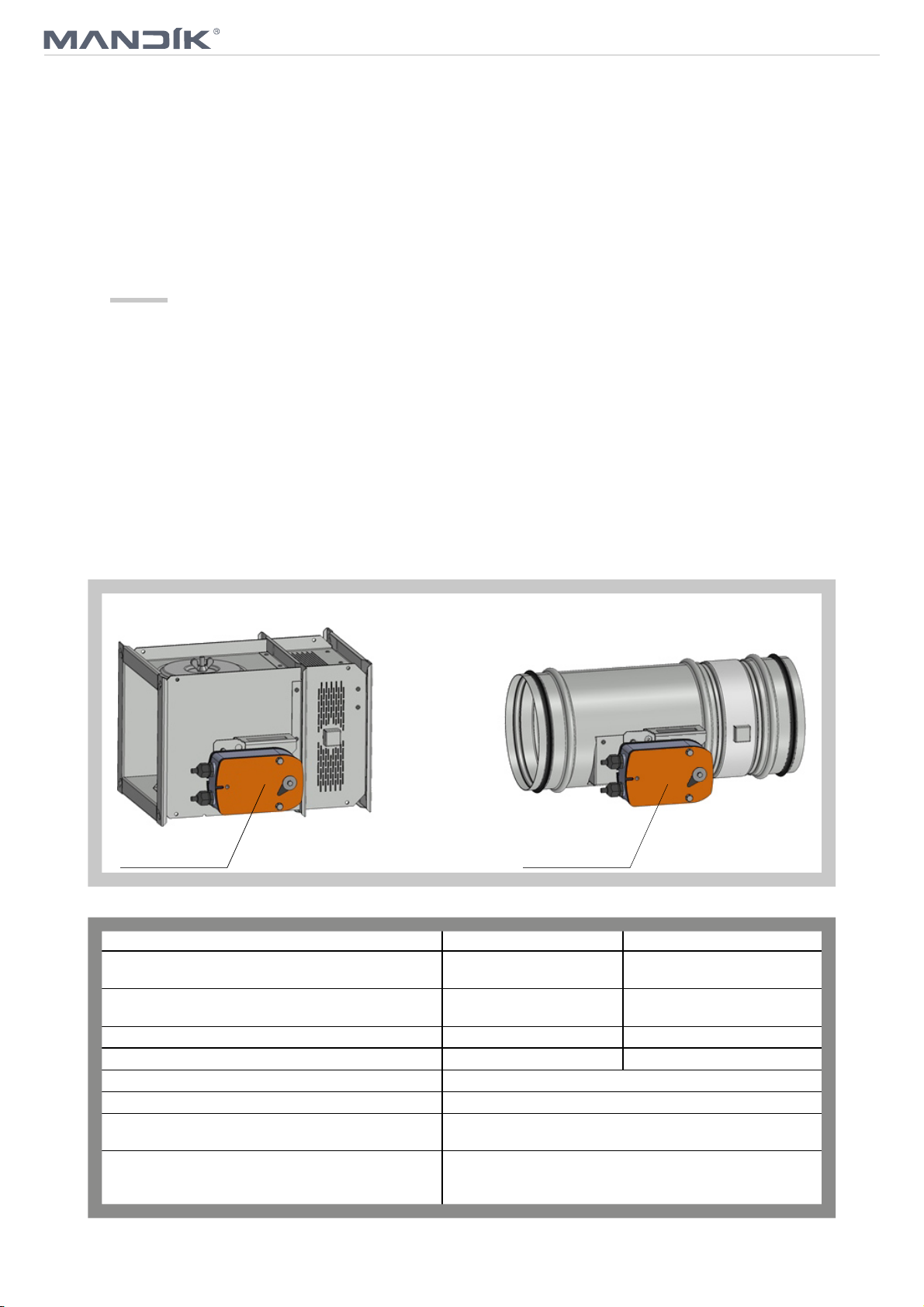
After being connected to power supply the actuating mechanism displaces the damper blade into
operation position "OPEN" or „CLOSED“ (according to method of connection, see connection
diagram). Running time is max. 60s. If is power supply cut off, actuating mechanism is stopped
in actual position. The crank handle supplied with the actuator allows it to be operated manually.
Signaling of the damper blade positions "OPEN" and "CLOSED" is provided by means of two
integrated, invariably set terminal switches.
Fig. 3 Damper with actuating machanism
Actuating mechanism
Tab. 2.1.1. Actuating mechanism BELIMO BLE 24(-ST), BLE 230
Actuating mechanism BELIMO BLE 24(-ST) BLE230
Nominal voltage AC 24V 50/60Hz
Power consumption - motoring
- holding
Dimensioning 9 VA (Imax 2,7 A @ 5 ms) 12 VA (Imax 6 A @ 5 ms)
Protection class III II
Degree of protection IP 54
Running time for 95° < 30 s
Ambient temperature range
Non-operating temperature
Connecting - motor
- auxiliary switch
Actuating mechanism
AC 230 V 50/60Hz
DC 24 V
7,5 W
< 0,5 W
- 30 °C … + 50 °C
- 40 °C … + 80 °C
cable 1 m, 3 x 0,75 mm
cable 1 m, 6 x 0,75 mm
(BLE 24-ST) with plug-in connectors
5W
< 1 W
2
2
3
TPM 109/15
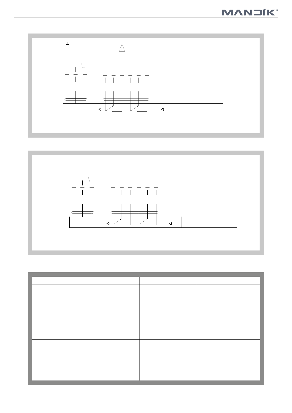
Fig. 4 Actuating mechanism BELIMO BLE 24(-ST)
~
AC 24 V
DC 24 V
+-
Connection through
an insulation transformer.
BLE24-ST: Design with connector plugs for communication
to network and communication device BKNE230-24
213
<3°
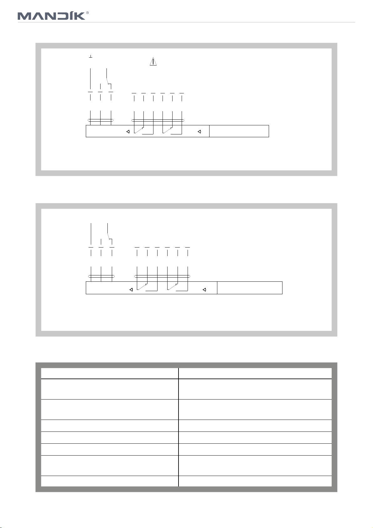
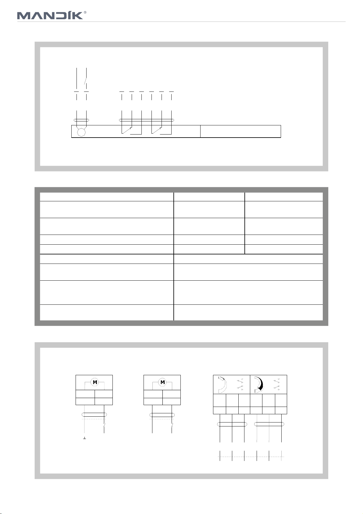
Fig. 5 Actuating mechanism BELIMO BLE 230
N
L1
1
2
3
S2S1 S3 S5S4 S6
AC230 V
<3° <87°
S3S2S1 S6S5S4
<87°
Parrallel connection of other driver is possible.
Pay attention to the power input data.
BLE24 (-ST)
BLE230
Parrallel connection of other driver is possible.
Pay attention to the power input data.
Tab. 2.1.2. Actuating mechanism BELIMO BE 24-12(-ST), BE 230-12
Actuating mechanism BELIMO BE 24-12 (-ST) BE230-12
Nominal voltage AC 24V 50/60Hz
DC 24 V
Power consumption - motoring
- holding
Dimensioning 18 VA (Imax 8.2 A @ 5 ms)
Protection class III
Degree of protection IP 54
Running time for 95° < 60 s
Ambient temperature range
Non-operating temperature
Connecting - motor
- auxiliary switch
12 W
0,5 W
- 30 °C … + 50 °C
- 40 °C … + 80 °C
cable 1 m, 3 x 0,75 mm
cable 1 m, 6 x 0,75 mm
(BE 24-ST) with plug-in connectors
AC 230 V 50/60Hz
8W
0,5 W
15 VA (Imax 7.9 A @ 5 ms)
II
2
2
4
TPM 109/15
Fig. 6 Actuating mechanism BELIMO BE 24-12(-ST)
~
+-
AC 24 V
DC 24 V
Connection through
an insulation transformer.
BE24-12-ST: Design with connector plugs for communication
to network and communication device BKNE230-24
213
<3° <87°
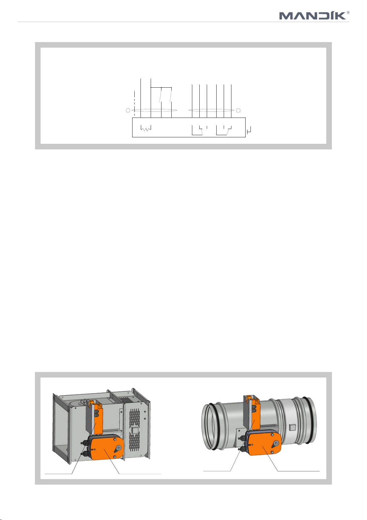
Fig. 7 Actuating mechanism BELIMO BE 230-12
N
L1
1
2
3
S2S1 S3 S5S4 S6
AC230 V
S3S2S1 S6S5S4
BE24-12 (-ST)
Parrallel connection of other driver is possible.
Pay attention to the power input data.
<3° <87°
Tab. 2.1.3. Actuating mechanism SCHISCHEK InMax 50.75-S
Actuating mechanism SCHISCHEK
Nominal voltage
Power consumption - motoring
- heating
BE230-12
Parrallel connection of other driver is possible.
Pay attention to the power input data.
InMax 50.75-S
24-240 VAC/DC 50/60Hz
10 W
16 W (start at -20°C)
Protection class I
Degree of protection IP 66
Running time for 95° < 60 s
Ambient temperature range
Non-operating temperature
- 40 °C … + 50 °C
- 40 °C … + 70 °C
Connecting cable 1 m, 0,5 mm
5
2
TPM 109/15
Fig. 8 Actuating mechanism SCHISCHEK InMax 50.75-S
24...230 VAC/DC
+-
~
~
Integrated aux. switches
max 24V/3A, 240V/0,25A switching
at 5° and 85°.
<5°
>85°
PE
a
b
A B
1
heater
2 3
4
1
2 3
4 5
6
PA
2.2. Design with the communication and supply device
Design .66
Design with the communication and supply device BKNE230-24 and the actuating mechanism
BLE24(BE24-12)-ST.
BKNE230-24 functions as a decentralized network device for supplying the actuating mechanism
BLE24(BE24-12)-ST on one hand and on the other hand it transmits signals from communication
and control device BKSE24-6.
It simplifies electrical wiring and interconnection of dampers. It facilitates on site check and
enables central control and checks of fire damper by means of a simple 2-conductor wiring.
BKNE230-24 signals the damper position „OPEN“/„CLOSED“ (from switches on the actuator)
and any fault alarms to the BKSE24-6 unit. It also receives positioning commands from the
control unit and triggers the actuator to the required position. The last control command is
retained troughout temporary power failures.
The BKNE230-24 unit monitors the positions of the switches on the actuator, its running time and
the exchange of data with the control and monitoring unit BKSE24-6. It also monitors the actuator
current and the power supply. In order to make installation as simple as possible the smoke
extraction damper actuators ...-ST are fitted with plug connectors that can be inserted directly into
the BKNE230-24 unit.
The 2-wire conductor must be connected to screw terminals 6 and 7. It is recommended that a
fire alarm signal cable suitable for the application be used for the 2-wire conductor. It is essential
to ensure the correct polarity. More information in catalogue Belimo.
Design .66 is not available by using actuating mechanism InMax 50.75-S
Fig. 9 Damper with actuating mechanism and BKNE230-24
Actuating mechanismBKNE230-24
BKNE230-24
Actuating mechanism
6
TPM 109/15
Tab. 2.2.1. Communication and supply device BKNE 230-24
Communication and supply device BKNE 230-24
Nominal voltage AC 230V 50/60Hz
Power consumption 10 W (including actuating mechanism)
Dimensioning 19 VA (including actuating mechanism)
Degree of protection II
Ambient temperature range
Non-operating temperature
Connecting - net
- actuator
- terminal board
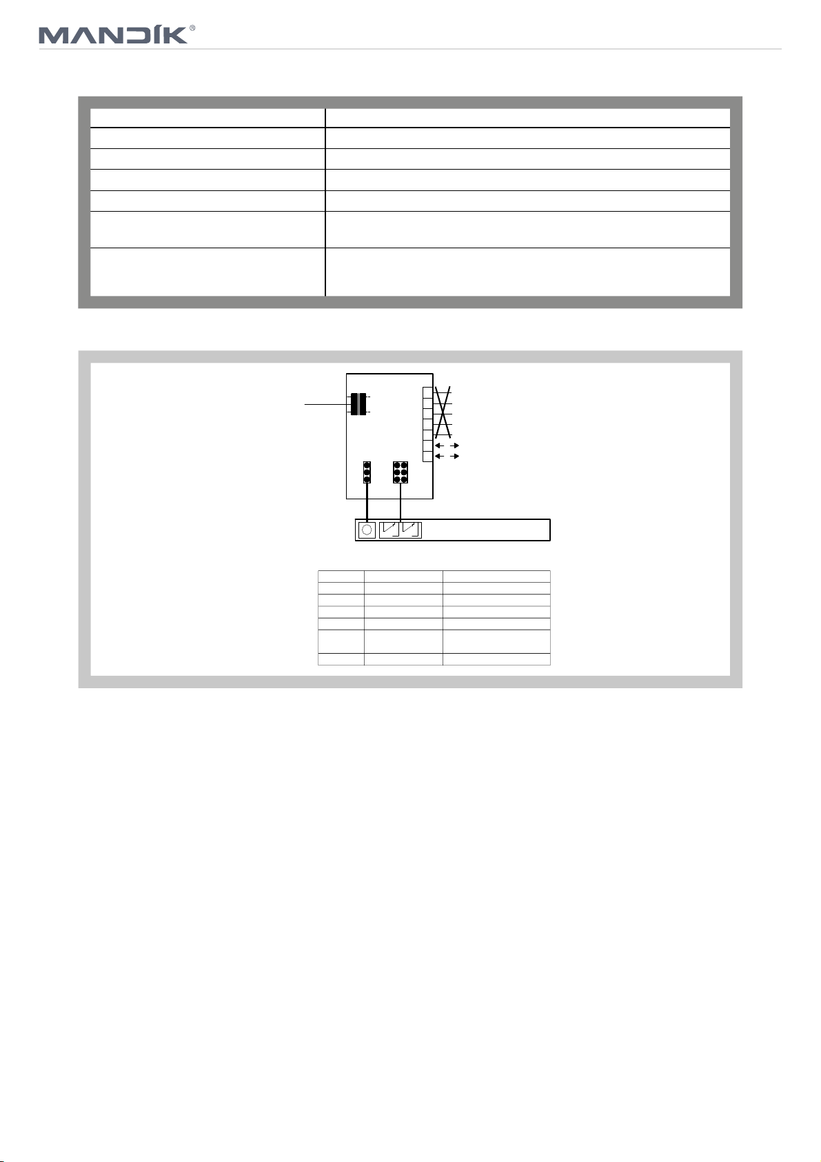
Fig. 10 Communication and supply device BKNE 230-24
6-pole connector, 3-pole connector
screw terminals for cable 2x1,5 mm
- 30 °C … + 50 °C
- 40 °C … + 80 °C
cable 1 m without plug
2
AC 230 V
BKNE230-24
M
Displays
LED Stav Funkce
yellow flashing light damper moving to OPEN
yellow steady light damper open
green flashing light damper moving to CLOSED
green steady light damper closed
yellow flashing at double
or
green frequency
yellow dark power failure
+green
1
2
Nothing must be assigned
3
to terminals 1 to 5
4
5
a
2-wire conductor
6
to BKSE24-6
b
7
BE(G)24-ST, BE24-12-ST
fault
2.3. Design with electric actuating mechanism with emergency function and electromagnet
Design .4M0, .4M1, .5M0 and .5M1
MSD-W is always equipped by electric actuating mechanism BLF 230-T, BLF 24-T, DAF2.20S or
DAF1.20S (further only "actuating mechanism") and is complemented with initiation by means of
an electromagnet (solenoid). After being connected to power supply AC/DC 24V or 230V, the
actuating mechanism displaces the damper blade into operation position "CLOSED" and at the
same time it pre-stretches its back spring. When the actuating mechanism is under voltage, the
damper blade is in the position "CLOSED" and the back spring is pre-stretched. Time needed for
full closing of the flap blade from the position "OPEN" to the position "CLOSED" is maximum
60 sec. This possition is secured by initional lever. If the actuating power supply is cut off damper
is still in the position "CLOSED". After activation of electromagnet is released initiation lever and
the back spring displaces the damper blade into the breakdown position "OPEN". The time of
displacing the blade from the position "OPEN" to the position "CLOSED" takes maximum 16 sec.
In case that the power supply is restored again (the blade can be in any position), the actuating
mechanism starts to re-displace the damper blade into the position "CLOSED".
By voltage AC 230 V is damper equipped by electromagnet EM230. By voltage AC/DC 24 V is
damper equipped by electromagnet EM230 with pre-pulse switch SIEM24. SEIM24 activates the
electromagnet after capacitor charge witch is placed inside of SIEM24. It takes about 10 sec.
Charging time depends on the current supply. For reliable operation is necessary connect to
electromagnet or pre-pulse switch appropriate supply for 2 sec (230 V) or 20 to 30 sec (24 V).
7
TPM 109/15
Fig. 11 Electric actuating mechanism with emergency function and electromagnet
Pulse switch
Tab. 2.3.1. Actuting mechanism BELIMO BLF 24, BLF 230
Electromagnet (solenoid) Pulse switch
Actuating mechanism
Electromagnet (solenoid)
Actuating mechanism
Actuting mechanism BELIMO BLF 24 BLF230
Nominal voltage AC 24V 50/60Hz
AC 230 V 50/60Hz
DC 24 V
Power consumption - motoring
- holding
5 W
2,5 W
Dimensioning 7 VA (Imax 5,8 A @ 5 ms)
Protection class III
7 VA (Imax 150 mA @ 10 ms)
5W
3W
II
Degree of protection IP 54
Running time - motor
- spring return
< 120 s
~ 16 s
Ambient temperature
- normal duty
- safety duty
- non-operating temperature
Connecting - motor
- auxiliary switch
The safe position will be attained up to max. 75°C
- 30 °C … + 50 °C
- 40 °C … + 50 °C
cable 1 m, 2 x 0,75 mm
cable 1 m, 6 x 0,75 mm
2
2
Obr. 12 Actuting mechanism BELIMO BLF 24
~
AC 24 V
DC 24 V
+-
1
2
M
<5° <80°
Connection through
an insulation transformer.
S2S1 S3 S5S4 S6
BLF24
Parrallel connection of other driver is possible.
Pay attention to the power input data.
8
TPM 109/15
Obr. 13 Actuting mechanism BLF 230
L1
2
M
AC230 V
S3S2S1 S6S5S4
<5° <80°
N
1
Tab. 2.3.1. Actuting mechanism Joventa DAF2.20S a DAF1.20S
For separation from the mains, a device that
insulates polar conductors must be at disposal
(Minimum distance between contacts - 3 mm).
BLF230
Parrallel connection of other driver is possible.
Pay attention to the power input data.
Actuting mechanism Joventa DAF2.20S DAF1.20S
Nominal voltage AC 24V 50/60Hz
AC 230 V 50/60Hz
DC 24 V
Power consumption - motoring
- holding
26 VA (AC); 15,6 W (DC)
9,3 VA (AC); 2,6 W (DC)
Dimensioning 14 VA
Protection class II
0,15 A
0,09 A
14 VA
II
Degree of protection IP 54
Running time - motor
- spring return
24…57 s
11…15 s
Ambient temperature
- normal duty
- non-operating temperature
Connecting - motor
- auxiliary switch
Obr. 14 Actuting mechanism Joventa DAF2.20S a DAF1.20S
DAF2.20S DAF1.20S LIMIT SWITCHES
M
BLK1RED
2
~
+-
AC 24 V
M
BLK
RED
1
2
N L1
AC230 V
DC 24 V
- 40 °C … + 55 °C
- 65 °C … + 85 °C
cable 1,2 m halogen-free; 2-wires
cable 1,2 m halogen-free; 6-wires
BLK/
RED
21
COM
S1
BLK/
BLU
22
NC
21
22
23
21
BLK/
GRY
23
NO
WHT/
RED
24
COM
S2
WHT/
BLU
25
NC
24
24
25
26
WHT/
GRY
26
NO
9

TPM 109/15
Tab. 2.1.2. Elektromagnet EM230
Elektromagnet EM230
Jmenovité napětí AC 230 V / 50 Hz
Zátahový proud 1,2 A
Krytí IP 40
Teplota okolí provozní -10 °C … +40 °C
Obr. 15 Elektromagnet EM230
Připojení kabel 1m, 3x0,75mm
2
3. Communication and control devises
3.1. BKSE24-6 indicates operating status and fault signals for the smoke extraction dampers. The
auxiliary contacts that are incorporated also allow functions to be signaled or passed on to
higherlevel control systems. The signals from the BKNE230-24 unit are received by the
BKSE24-6 unit and evaluated individually. All BKNE230-24 units are triggered simultaneously. To
BKSE24-6 can be connected max. 6 BKNE230-24.
Communication is via the 2-wire conductor. Correct operation of the dampers is indicated by
means of two LEDs. The operating status of the SBSE-Control system and any faults are also
indicated by this LED and the corresponding fault LED.
The BKSE24-6 unit can be clipped directly to a 35 mm DIN mounting rail and connected by means
of two 9-pole plug-in terminals.
Tab. 3.1.1. Communication and control devices BKSE 24-6
Communication and control devices
BKSE 24-6
Nominal voltage AC 24 V 50/60Hz
Power consumption 3,5 W (operating position)
Dimensioning 5,5 VA 18 VA (Imax 6.4 A @ 2.5 ms)
Protection class III
Degree of protection IP 20
Ambient temperature range 0 … + 50 °C
Connecting screw terminals for cable 2x1,5 mm
2
10
TPM 109/15
Fig. 16 Communication and control devices BKSE 24-6
SMOKE EXTRACTION
CEASE SMOKE EXTRACTION
AC 24 V
Connection through
an insulation transformer.
4. Dimensions, weights
~
AUTO
Input 1
10
11
12
COM
Delay 0 s (Fan)
Delay 60 s (Fan)
OPEN
CLOSED
*Fault (Error)
*Inverted output: fault = contact open
13
14
15
16
17
18
BKSE24-6
9
8
7
6
5
4
3
2
1
+
-
Input 2
(isolated)
U
a1...a6
a1...a6
BKNE230-24
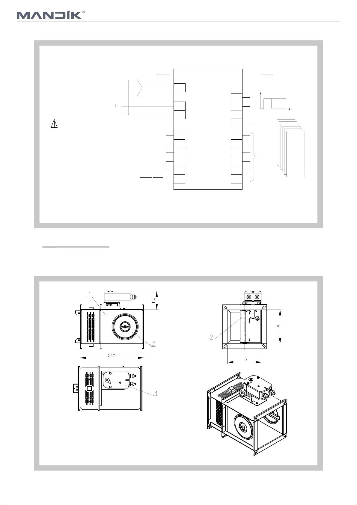
4.1. Dimensions
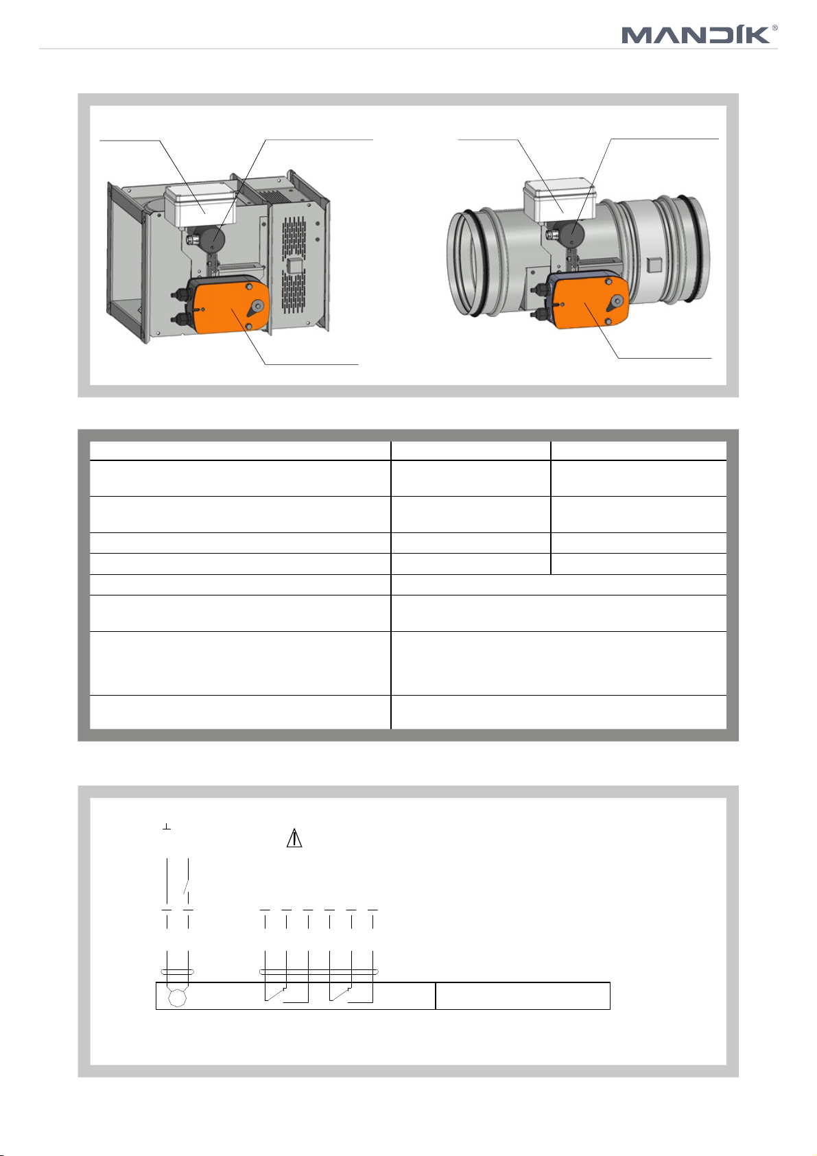
Fig. 17 Square MSD (MSD-W) - design with actuating mechanism
Position:
1 Damper body 3 Inspection hole covering
2 Damper blade 4 Actuating mechanism
11
 Loading...