

Mandik HELIOS Instructions Manual
1. Description of infrared heater HELIOS .............................................................................…
2. Description of function.......................................................................................................….
3. Versions…...................................................................................................................….…..
4. Dimensions and weights...............................................................................................….….
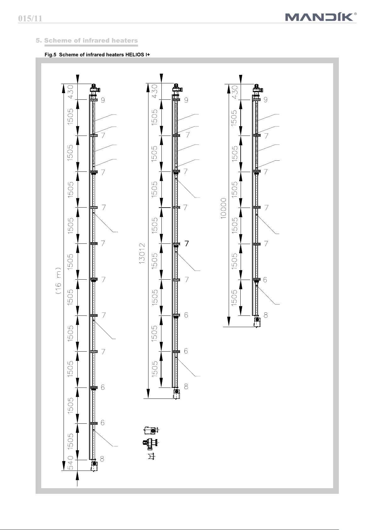
5. Scheme of infrared heaters....….…....................................................................................….
6. Pressure losses.................................................................................................................….
7. Examples of flue gas exhaust and combustion air supply solutions...............................….….
10
8. Data label…….….........................................................................................................….…..
9. Mounting components of infrared heater HELIOS.....................................................….…….
10. Mounting of infrared heater body....................................................................................….
11. Installation of burner box………………......................................................................….…..
12. Installation of the exhaust box...................................................................................….…..
13. Gas connection installation......................................................................................….……
14. Electrical installation....................................................................................….…….……….
15. Adjustment procedure, adjustment values.......................................................................….
16. Operating Instructions..........................................................................................................
17. Maintenance........................................................................................................................
18. Failure of infrared heaters HELIOS and their removal.................................................….….
19. Conversion to another type of fuel....................................................................................….
20. Components used in infrared heaters HELIOS..............................................................……
21. Control box.........................................................................................................….………..
22. Wiring diagram..........................................................................................….……….………
23. Economizer functional description........................................................................................
24. Pressure loses on flue gas side......................................................................................….
25. Dimensions of economizer.....................................................................................….……..
26. Technical data and wiring diagram of economizer.....................................................….…..
27. Installation of economizer............................................................................................….…
12
15
15
23
23
24
24
3
3
4
4
5
9
25
31
32
32
34
35
35
37
38
38
39
39
40
2
Dark tube infrared heater HELIOS (On/Off) and HELIOS D (two-stage) in the performance series from
10 to 50 kW is a modern ecological gas heater.
In terms of operating temperature of active surfaces and thus in terms of the particular wavelength of
the emitted radiation, the device belongs to the category of so-called "dark" infrared heaters. The active
surface is formed by radiant pipes and a reflector. In the radiant pipes there is the process of fuel gas
burning and there are also burnt gases flowing through the pipes to the mouth of the exhaust fan. Fuel
burning is carried out by an atmospheric burner which is automatically controlled. The reflector prevents
the pipes from cooling by the process of convection. The reflector itself warms up by the radiant pipes
and radiates the heat in the required direction.
Normal operating fuel of the HELIOS infrared heaters:
● natural gas – NG (G20/G25)
● propane – P (G31)
Product category:
● II
2E3B/P
, II
, design A2, B22, C12, C32, C62. Třída NOX 3 (acc. EN 416-1/A1).
2ELL3B/P
Infrared heaters HELIOS are intended for environment protected against weather impacts with the
classification of climatic conditions class 3K5 acc. EN 60721-3-3 with temperature range from 0° to
35°C, for BNV premises acc. EN 1127-1. Installing infrared heaters as design C is possible, except of
normal spaces also in areas intended for decommissioning and maintenance of vehicles. Such
installation must be assessed by the competent authorities in accordance with the applicable regulations.
Infrared heaters cannot be installed in individual, row and collective garages, motor vehicle garages and
operating rooms of fuel filling stations with fuel dispensers. Infrared heaters cannot also be installed in
places where there is a risk of fire or explosion or high levels of flammable dust.
Infrared heaters are suspended under the ceiling or on the walls in the upper areas of the buildings so
that the radiated beams point to the floor towards the heated residential zone. The surfaces of floors,
walls, machines and other objects are heated by radiation and the surrounding air is heated from them.
The infrared heater HELIOS consists of the following main parts:
●
● with hinges and the radiant heating tubes "U" or "I"
The basic design of the burner box is scalded by the throat for the external suction in the upper part of
the burner box. If the combustion air supply system is not connected, it is an open gas appliance. Thus,
infrared heaters can only be used in a basic (normal) environment according to the according to the
relevant standard. In order to be considered as a closed gas appliance, the radiator must be connected
to outdoor air intake system.
● Infrared heater operation is controlled by the located in the burner box.
● After connecting to the el. network, first the basic test of the connected devices to the automatic is
performed and if everything is OK, the exhaust fan is activated.
● After the fan starts and a vacuum is evoked in the burner chamber, the differential air manostat is
switched. The manostat senses the pressure differential caused by the exhaust fan.
● When the manostat is switched on, the venting time (approx. 50 s) starts to run, this is used to
ventilate the flue gas exhaust pipe and heating tubes.
● After this ventilation time, the electromagnetic double valve is opened and gas is injected into the
burner. At the same time, the ignition system is put into operation by the automatic system.
● The ignition of the gas mixture in the burner is detected by the ionisation electrode.
● If the gas mixture in the burner is not ignited within 5 seconds, the valve closes the gas supply and
the unburned gas / air mixture is vented through the exhaust fan during the next ventilation time. After
it has elapsed, the automation runs two more ignition cycles.
● If no flame is detected during the third ignition cycle, the automatic switches into the fault mode and
the red indicator “Burner Failure” light on.
● Further start is possible after unlocking the fault condition by disconnecting and reconnecting to the
power supply.
● After putting the burner into operation and igniting the gas mixture, the green indicator "Power
supply" and orange indicator "Burner Operation" lights up.
3
The atmospheric burner control is single-stage or two-stage.
Infrared heater with single-stage burner works in on-off mode, two-stage burner of the infrared heater
operates in off mode - reduced power - full power.
The main advantages of the two-stage burner control include reducing burner start-up frequency, better
temperature distribution in the heated space and reduced energy consumption.
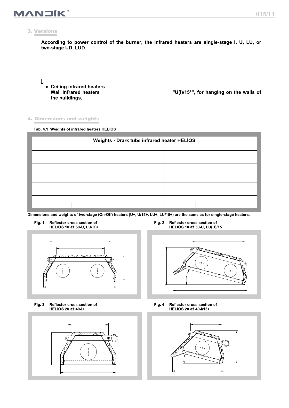
nfrared radiators HELIOS are divided in terms of installation and used reflector:
with reflectors fitted with hinges in version of hanging under the ceiling
● with reflectors fitted with hinges
Reflectors are supplied with insulation (thermal insulation, covered by a cover made of galvanized sheet
metal).
Size, type 10-U+ 10-U/15+ – – – –
Weight [kg] 77,5 80,4 – – – –
Size, type 20-U+ 20-U/15+ 20-I+ 20-I/15+ 20-LU+ 20-LU/15+
Weight [kg] 107,1 111,3 124,1 130,7 135,8 141,4
Size, type 30-U+ 30-U/15+ 30-I+ 30-I/15+ 30-LU+ 30-LU/15+
Weight [kg] 137 142,6 160,1 168,8 163,9 170,8
Size, type 40-U+ 40-U/15+ 40-I+ 40-I/15+ 40-LU+ 40-LU/15+
Weight [kg] 163,9 170,4 196,1 209,6 189,9 198,2
Size, type – – – – 50-LU+ 50-LU/15+
Weight [kg] – – – – 220 229,7
440
350
200
538
250
200
340
290
15°
15°
408
425
600
241,5
260
4
Black tube 4595 mm - 1 socket
Black tube 3290 mm - 1 socket
Black tube 4595 mm - 2 sockets
Black tube 3090 mm - 2 sockets
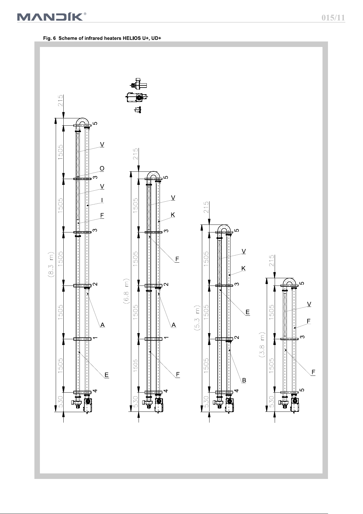
V
HELIOS 40 I+
HELIOS 30 I+
HELIOS 20 I+
V
V
O
V
H
E
O
V
H
K
O
V
H
F
I
B
I
A
A
Burner box ''HS''
Exhaust box ''OS''
Socket tube joint
with clamp
5
Key:
6 Hinge I type 6
7 Hinge I type 7
8 Hinge I type 8
9 Hinge I type 9
A Stainless steel tube INOX 3080 mm
B Stainless steel tube INOX 1580 mm
E
F Black tube 3090 mm - 1 socket
H
I
K
O Wire eye for spinners
V Spinner
Stainless steel tube INOX 1580 mm
Black tube 1585 mm - 1 socket
Black tube 4595 mm - 2 sockets
Burner box ''HS''
HELIOS 40 U+
HELIOS 30 U+
HELIOS 20 U+
HELIOS 10 U+
Exhaust box ''OS''
Socket tube joint
with clamp
Key:
1 Hinge U type 1
2 Hinge U type 2
3 Hinge U type 3
4 Hinge U type 4
5 Hinge U type 5
A Stainless steel tube INOX 3080 mm
B
E Black tube 4595 mm - 1 socket
F Black tube 3090 mm - 1 socket
G
I
K Black tube 3090 mm - 2 sockets
O Wire eye for spinners
V Spinner
6
Key:
Stainless steel tube INOX 1580 mm
Black tube 1585 mm - 1 socket
Black tube 4595 mm - 2 sockets
3
5
1
3
3
2
1
1
1
1
4
4
4
4
2
2
2
3
3
3
3
3
3
5
5
5
K
F
F
C
E
K
E
A
A
B
E
I
F
F
V
V
O
I
F
V
V
O
F
V
V
O
F
E
V
V
O
V
O
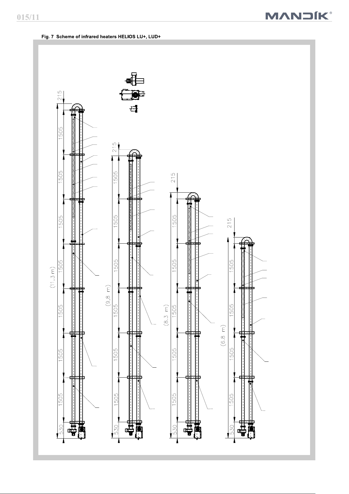
HELIOS 50 LU+
HELIOS 40 LU+
HELIOS 30 LU+
HELIOS 20 LU+
1 Hinge U type 1
2 Hinge U type 2
Burner box ''HS''
Exhaust box ''OS''
Socket tube joint
with clamp
3 Hinge U type 3
4 Hinge U type 4
5 Hinge U type 5
A Stainless steel tube INOX 3080 mm
B
C Stainless steel tube INOX 4580 mm
E Black tube 4595 mm - 1 socket
F Black tube 3090 mm - 1 socket
G
I
K Black tube 3090 mm - 2 sockets
O Wire eye for spinners
V Spinner
7
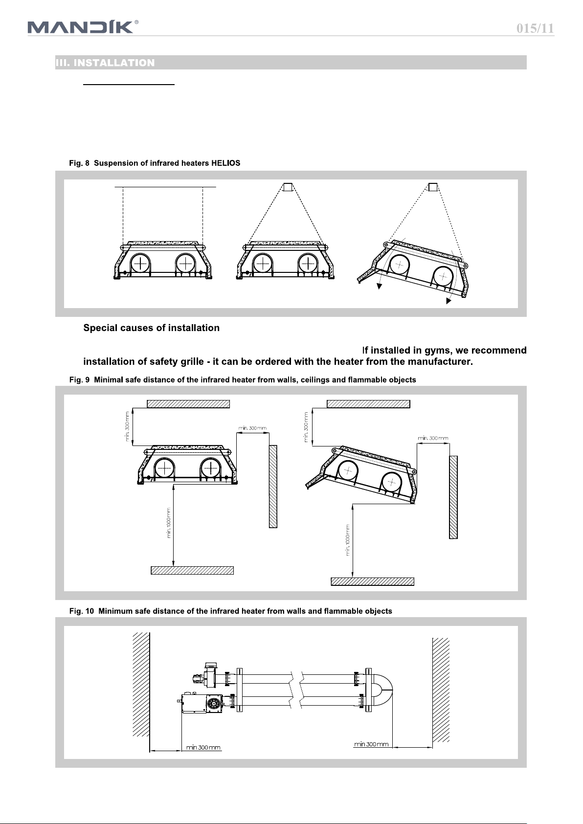
Suspension methods:
1. Dark tube infrared heaters can be suspended on suitable structure by means of chains or strings and
snap-hooks or tie rods.
2. According to the picture 8 it is necessary to fix the infrared heater at least on two places by using an
appropriate way so that the device cannot be turned around.
3. Due to the thermal expansion, the infrared heater can not be fixed directly to the supporting structure.
4. It is necessary to keep safe distance from flammable objects and walls (Fig. 9, 10).
When installing the heater over the runway of bridge crane, it is necessary to use the protection of
electrical power installation of the crane against excessive heat.
8
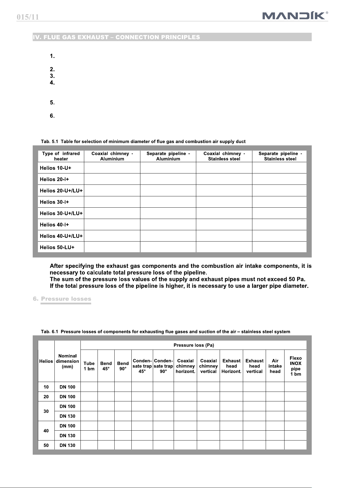
The flue gas duct must be in accordance with applicable standards and regulations.
Minimum internal diameter of the pipeline for Helios 10 to Helios 40 is 100 mm, for Helios 50 is
internal diameter of the pipeline 125 mm.
Connecting of the combustion gases to the ventilator must be demountable.
The duct system must prevent the condensate from penetration into the exhaust pipeline.
The duct system must be terminated freely in the exposed position so that the flue gases cannot
face any resistance, and also that combustion products cannot return back to the building through
windows.
The material of flue gases exhaust must be resistant to corrosion and against flue gases temperature according to relevant standards.
Opening for flue gases measurement is placed according to heater configuration, for heaters without
economizer the opening is in the first part of the duct immediately after the heater, for heaters with
economizer, the opening is in the first part of the flue duct immediately after the economizer.
DN 100 DN 100 DN 100 DN 100
- DN 100 - DN 100
DN 100 DN 100 DN 100 DN 100
- DN 100 - DN 100
DN 125 DN 100 DN 100 DN 100
- DN 100 - DN 100
DN 125 DN 100 DN 100 DN 100
DN 125 DN 125 DN 130 DN 130
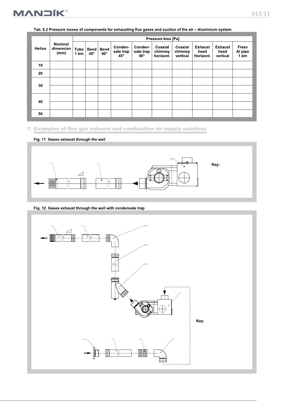
For pressure losses of individual flue system components see following tables.
Total pressure loss of flue system can be calculated as sum of pressure losses of all components used.
1,5 1,5 2 2 4 16 23 3 4 5 2
2 3 4 4,5 7 23 31 5 7 8 4
3 4 6 7 11 29 35 9 11 13 6
1 1,5 3 3,5 5,5 16 18 4,5 5,5 6,5 3
3,5 4,5 7 8 14 35 44 11 14 16 7
1,5 2 4 4,5 8 19 22 5 6 8 4
2 3 6 6 12 27 32 7 9 12 6
9
DN 100 2 2,5 5 3,5 7 18 20 4 5 3
Join female-female
Exhaust head horizontal
Air intake head
DN 100 3 4 6 6 11 26 29 6 8 5
DN 100 3,5 5 7 9 14 58 63 11 13 7
DN 125 2 3,5 5 6 10 20 20 8 9 5
DN 100 4 6 8 11 16 102 112 14 16 8
DN 125 3 4 6 6 11 35 35 10 11 6
DN 125 4 6 9 10 16 51 51 15 16 9
23
1
2%
6
3
4
1 Helios heater
2 Tube with throat
3 Exhaust head
horizontal
2%
3
2
1
1 HELIOS heater
7
3
5
4
2 Condensate trap
3 Tube with throat
4 Bend
5
6
7
10
5
Air intake head
3
4
2
1
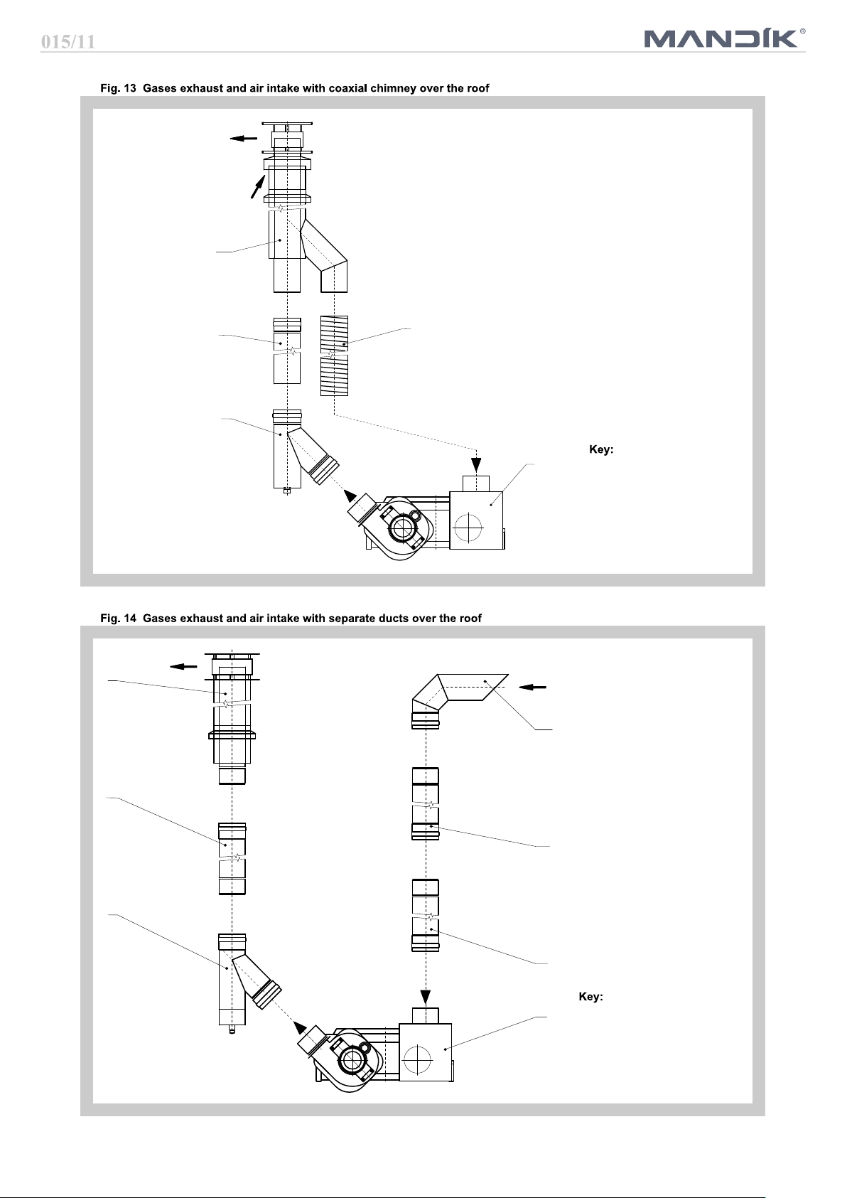
1 HELIOS heater
2 Condensate trap
3 Tube with throat
4 Flexible duct Al
5 Coaxial chimney
vertical
4
5
3
3
2
3
1
1 HELIOS heater
2 Condensate trap
3 Tube with throat
4 Exhaust head vertical
5
11
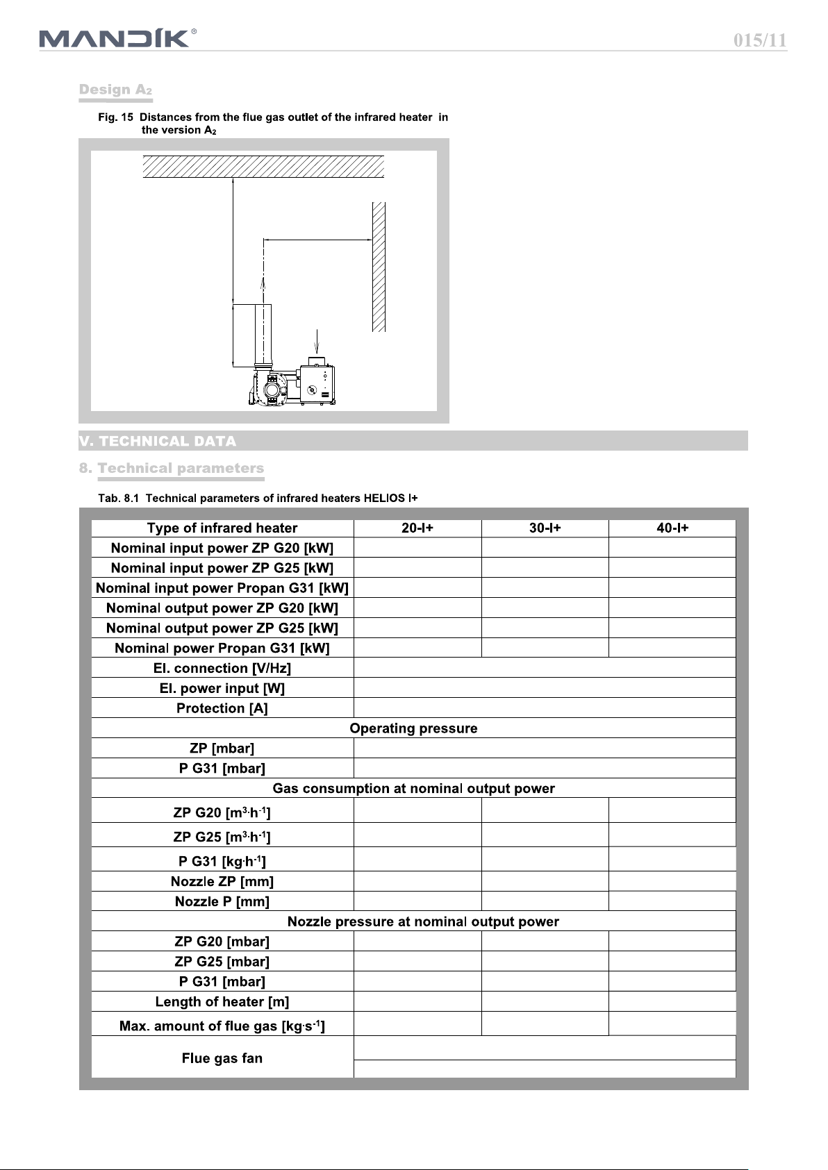
Min. 500 mm
The flue gas exhaust is forced by the flue
gas duct inside the building. The appliance
is classified according to the flue into
design version A . The design and installa-
2
tion of the flue gas exhaust must comply
Min. 1000 mm
according the correct norm.
When installing the heater in design A in
2
enclosed space, it is necessary to ensure
Min. 2000 mm
forced ventilation with min. 10 m / h for
3
each installed kW power consumption of
the heater in design A and it is necessary
2
to ensure that the device will stop in the
case of non-functional ventilation.
If inclined heaters are installed, rotate the
exhaust cabinet so that the flue gas is
directed vertically upwards.
19,9 36,5 41,0
18,5 33,9 38,2
19,9 33,0 41,0
18,0 33,2 37,3
16,7 30,8 34,8
18,0 30,0 37,3
230/50
100
4
17 - 26
28 - 50
2,07 3,84 4,25
2,15 3,98 4,40
1,51 2,48 3,09
4,0 5,0 5,5
2,6 3,3 3,8
9,5 11,5 10,5
13 14 13,5
25 23 21
10 13 16
0,018 0,028 0,031
max. 350 m3.h
-1
max. 360 Pa
12
 Loading...