

Mandik FDMC General Information Manual


TPM 083/12
These technical specifications state a row of manufactured sizes and models of fire dampers (further only dampers)
FDMC. It is valid for production, designing, ordering, delivery, assembly and operation.
I. CONTENT
II. GENERAL INFORMATION 2
1. Description.........................................................................................................................
2. Damper Design..….............................................................................................................
3. Communication and control devices..............….................................................................. 6
4. Dimensions, weights........................................................................................................... 9
5. Placement and Assembly.................................................................................................... 10
6. Statement of installations.................................................................................................... 12
7. Suspension of fire dampers................................................................................................. 18
III. TECHNICAL DATA 21
8. Pressure loss...................................................................................................................... 21
9. Coefficient of local pressure loss......................................................................................... 21
10. Noise data......................................................................................................................... 22
IV. MATERIAL, FINISHING 24
11. Material............................................................................................................................. 24
VI. INSPECTION, TESTING 24
12. Inspection, testing............................................................................................................. 24
2
3
VI. TRANSPORTATION AND STORAGE 24
13. Logistic terms.................................................................................................................... 24
VII. ASSEMBLY, ATTENDANCE, MAINTENANCE AND REVISIONS 24
14. Assembly.......................................................................................................................... 24
15. Entry into service and revisions......................................................................................... 24
VIII. DATA OF PRODUCT 25
16. Data label..........................................................................................................................
17. Quick review.....................................................................................................................
25
25
IX. ORDERING INFORMATION 26
18. Ordering key.....................................................................................................................
26
1
TPM 083/12
II. GENERAL INFORMATION
1. Description
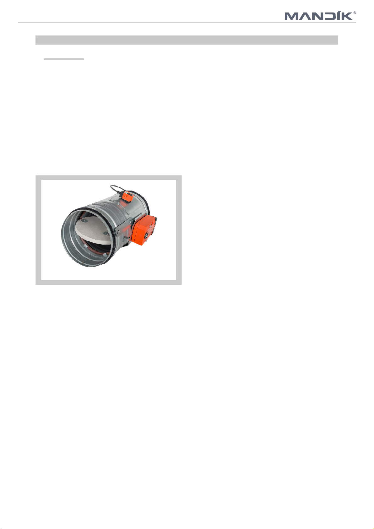
1.1. Fire dampers are shutters in duct systems of air-conditioning devices that prevent spreading the
fire and combustion products from one fire segment to the other one by means of closing the air
duct in the points of fire separating constructions.
Dampers blade automatically closes air duct using a shutting spring or an actuating mechanism
back spring. The back spring of the actuating mechanism is started when the thermoelectrical
starting mechanism BAE 72B-S is activated, when a reset button on BAE 72B-S is pushed or
when a power supply of the actuating mechanism is stopped.
The damper is sealed with a silicon packing against smoke penetration after closing the blade. At
the same time, the damper blade is bedded in a material which enlarges its capacity and air
proofs the air duct.
Dampers have one inspection hole, since the shutting device and the inspection hole can be set
into the most advantageous position (with respect to the operation and manipulation with the
control device).
Fig. 1 Fire damper FDMC
1.2. Damper characteristics
• CE certified acc. to EN 15650
• Tested in accordance with EN 1366-2
• Classified acc. to EN 13501-3+A1
• Fire resistance EIS 60
• External Casing leakage class min. C, Internal leakage class 3 (D=200 - 400 mm) and class 2
(D=180 mm) and class 1 (D=100 - 160 mm) acc. to EN 1751
• Cycling test in class C 10000 acc. to EN 15650
• Corrosion resistant acc. to EN 15650
• ES Certificate of conformity No. 1391-CPR-0090/2014
• Declaration of Perfomance No. CDM/FDMC/001/14
• Hygienic assessment of fire dampers - Report No. 1.6/13/16/1
1.3. Working conditions
Exact damper function is provided under the following conditions:
a) Maximum air circulation speed: 12 m.s
-1
Maximum pressure difference: 1500 Pa
b) Dampers could be displaced into position “CLOSED” only in case that ventilator, or Air
Handling Unit is switched off. The goal is the securing of proper closing and safe
function of Fire Damper in case of Fire.
c) The air circulation in the whole damper section must be secured as steady on whole
surface.
2
TPM 083/12
Operation of the dampers does not depend on the direction of air circulation. The dampers can
be located in an arbitrary position.
Dampers are suitable for systems without abrasive, chemical and adhesive particles.
Dampers are designed for macroclimatic areas with mild climate according to EN 60 721-3-3.
Temperature in the place of installation is permitted to range from - 20°C to + 50°C.
2. Damper design
2.1. Design with actuating mechanism
Design .40, .50
Design with an actuating mechanism BFL 230-T or BFL 24-T (further only "actuating mecha-
nism"). After being connected to power supply AC/DC 24V or 230V, the actuating mechanism
displaces the damper blade into operation position "OPEN" and at the same time it pre-stretches
its back spring. When the actuating mechanism is under voltage, the damper blade is in the
position "OPEN" and the back spring is pre-stretched. Time needed for full opening of the flap
blade from the position "CLOSED" to the position "OPEN" is maximum 140s. If the actuating
power supply is cut off (due to loss of supply voltage, activation of thermoelectrical actuating
mechanism or pushing the reset button on the thermoelectrical starting mechanism BAT), the
back spring displaces the damper blade into the breakdown position "CLOSED". The time of
displacing the blade from the position "OPEN" to the position "CLOSED" takes maximum 20 s. In
case that the power supply is restored again (the blade can be in any position), the actuating
mechanism starts to re-displace the damper blade into the position "OPEN".
A thermoelectrical starting mechanism BAT, which contains three thermal fuses Tf1 and Tf2, is a
part of the actuating mechanism. These fuses are activated when temperature +72 °C has been
exceeded (the fuse Tf1 when the temperature around the damper and the fuses Tf2 when the
temperature inside the air-conditioning piping has been exceeded). After the thermal fuse Tf1 or
Tf2 has been activated, the power supply is permanently and irreversibly cut off and the actuating
mechanism, by means of the pre-stretched spring, displaces the damper blade into the
breakdown position "CLOSED".
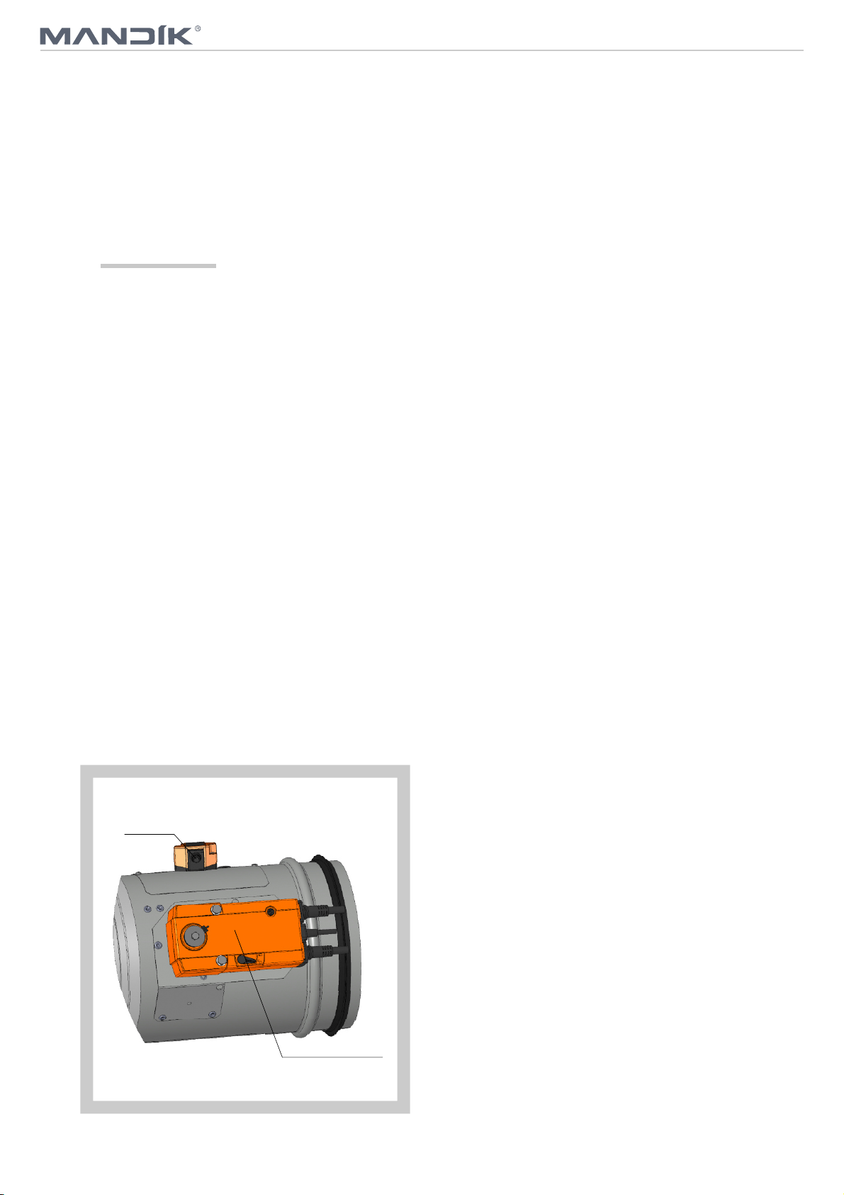
Signalling of blade positions "OPEN" and "CLOSED" is ensured by two firmly set integrated limit
switches.
Fig. 2 Fire damper FDMC - actuating mechanism
BAT
Actuating mechanism
3
TPM 083/12
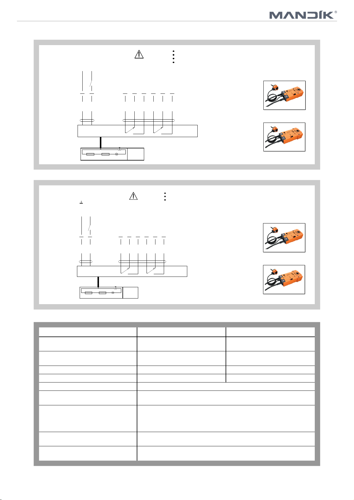
Fig. 3 Actuating mechanism BELIMO BFL 230-T
AC230 V, open-close
N
L1
1
2 S3S1 S2 S5S4 S6
<5° <80°
Tf Tf LED
BAT
Notes
Fig. 4 Actuating mechanism BELIMO BFL 24-T(-ST)
AC/DC 24 V, open-close
Notes
~
- +
Caution: Power supply voltage!
The actuator must be protected by a fuse that does not exceed 16 A.
Parallel connection of other actuators possible. Observe the performance data.
Combination of power supply voltage and safety extra-low voltage not permitted
at the both auxiliary switches.
BFL 230-T
Cable colours:
1 = blue
2 = brown
S1 = violet
S2 = red
S3 = white
S4 = orange
S5 = pink
S6 = grey
Connection via safety isolating transformer.
Parallel connection of other actuators possible. Observe the performance data.
Combination of power supply voltage and safety extra-low voltage not permitted
at the both auxiliary switches.
(-ST)
Plug connection to communication
and power supply units:
Application examples for integration
into monitoring and control systems
or into bus networks can be found in
the documentation of the connected
communication and power supply unit.
BFN 230-T
BFL 24-T
1
2 S3S1 S2 S5S4 S6
<5°
Tf Tf LED
BAT
<80°
Cable colours:
1 = blue
2 = brown
S1 = violet
S2 = red
S3 = white
S4 = orange
S5 = pink
S6 = grey
BFN 24-T
Tab. 2.1.1. Actuating mechanism BELIMO BFL24-T(-ST), BFN 24-T(-ST), BFL 230-T a BFN 230-T
Actuating mechanism BELIMO BFL, BFN 230-T BFL, BFN 24-T(-ST)
Nominal voltage
Power consumption - motoring
- holding
AC 230 V 50/60 Hz
3,5/5 W
1,1/2,1 W
AC 24 V 50/60 Hz
DC 24 V
2,5/4 W
0,8/1,4 W
Dimensioning 6,5/10 VA (Imax 4 A @ 5 ms) 4/6 VA (Imax 8,3 A @ 5 ms)
Protection class II III
Degree of protection IP 54
Running time - motor
- spring return
Ambient temperature
- normal duty
- safety duty
- non-operating temperature
Connecting - motor
- auxiliary switch
Thermal trips
The safe position will be attained up to max. 75°C
cable 1 m, 2 x 0,75 mm (BFL/BFN 24-T-ST) with 3-pin plug-in connectors
cable 1 m, 6 x 0,75 mm (BFL/BFN 24-T-ST) with 6-pin plug-in connectors
2
2
duct outside temperature 72 °C
duct inside temperature 72 °C
<60 s
~ 20 s
- 30 °C … 55 °C
- 40 °C … 55 °C
4

TPM 083/12
2.3. Design with the communication and supply device
Design .60
Design with the communication and supply device BKN 230-24 and the actuating mechanism
BFL 24-T-ST. It simplifies electrical wiring and interconnection of fire damper. It facilitates on site
check and enables central control and checks of fire damper by means of a simple 2-conductor
wiring.
BKN 230-24 functions as a decentralized network device for supplying the actuating mechanism
BFL 24-T-ST with a spring back drive on one hand and on the other hand it transmits the signal
information about the fire damper position OPERATION and FAILURE through 2-conductor
wiring to the central. Control command SWITCHED ON - SWITCHED OFF from the central
through BKN 230-24 goes through the same wiring to the actuating mechanism.
To simplify the connection, the actuating mechanism BFL 24-T-ST is equipped with connecting
plugs that are inserted directly to BKN 230-24. BKN 230-24 is supplied with a conductor and an
EURO plug to be connected to the 230V mains.
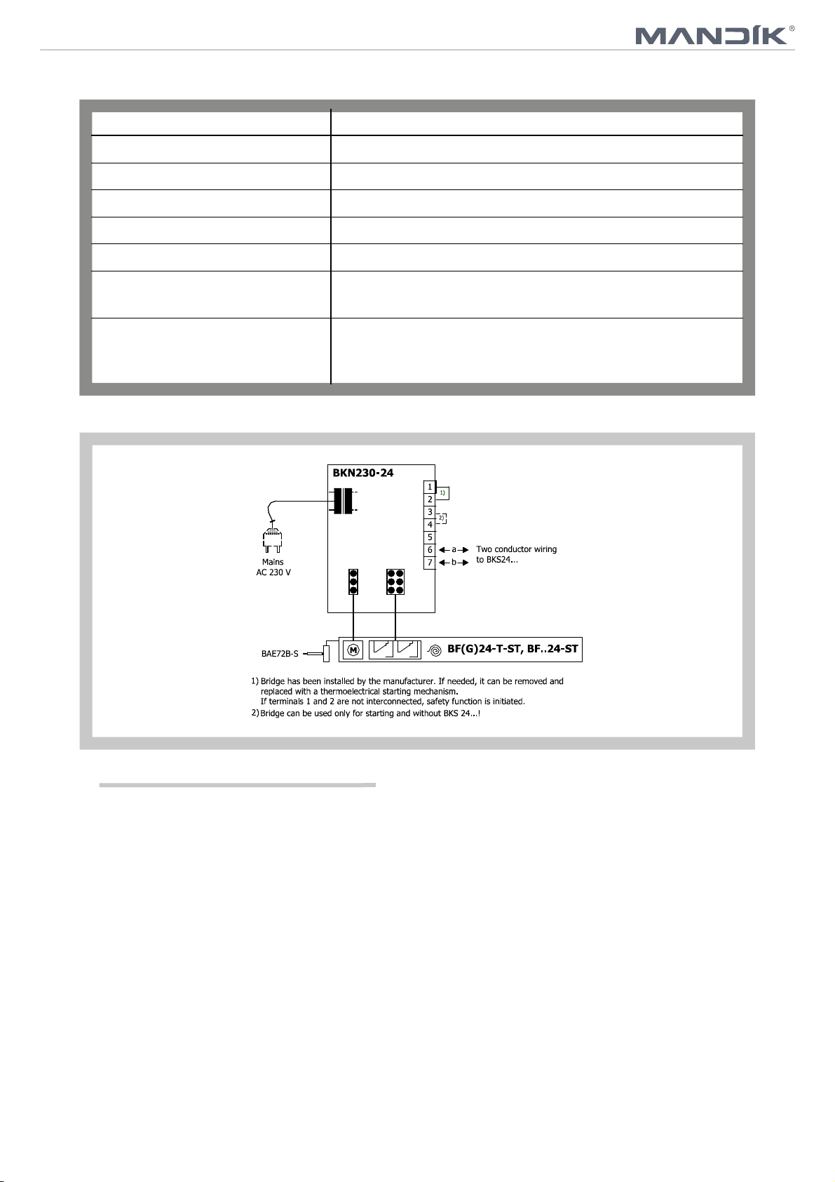
2- conductor wiring is connected to BKN 230-24 by means of terminals 6 and 7.
If the drive is supposed to be controlled without any signal from the central, it can be switched on
by means of a bridge between the terminals 3 and 4. A green LED pilot light on BKN 230-24 is
on when voltage is present in the drive (AC 24V). If the button on BAE 72-S is switched on or if
the power supply (e.g. by a signal from ELECTRICAL FIRE SIGNALISATION) is disconnected,
the fire damper position will be "FAILURE".
Communication and supply device BKN 230-24 has to be placed near the damper. It is necessary
for easy connection of actuating system equipped by BKN 230-24 device.
Fig. 5 Fire damper FDMD with actuating mechanism
and BKN
BAT
BKN
Actuating mechanism
Tab. 2.3.1. Communication and Supply Device BKN 230-24
Communication and Supply Device
Nominal voltage AC 230V 50/60Hz
Power consumption 3,5 W (operating position)
Dimensioning 11 VA (including actuating mechanism)
BKN 230-24
Protection Class II
Degree of protection IP 42
Ambient Temperature
Storage Temperature
Connection - mains
- drive
- terminal board
Cable 0,9 m with EURO plug of 26 type
screw terminals for conductor 2x1,5 mm
- 30 °C … + 50 °C
- 40 °C … + 50 °C
6 pole plug, 3 pole plug
5
2
TPM 083/12
Tab. 2.3.2. Communication and Supply Device BKN 230-24
Communication and Supply Device BKN 230-24
Nominal voltage AC 230V 50/60Hz
Power consumption 3,5 W (operating position)
Dimensioning 11 VA (including actuating mechanism)
Protection Class II
Degree of protection IP 42
Ambient Temperature
Storage Temperature
Connection - mains
- drive
- terminal board
Fig. 6 Communication and Supply Device BKN 230-24
- 30 °C … + 50 °C
- 40 °C … + 50 °C
Cable 0,9 m with EURO plug of 26 type
6 pole plug, 3 pole plug
screw terminals for conductor 2x1,5 mm
2
3. Communication and control devices
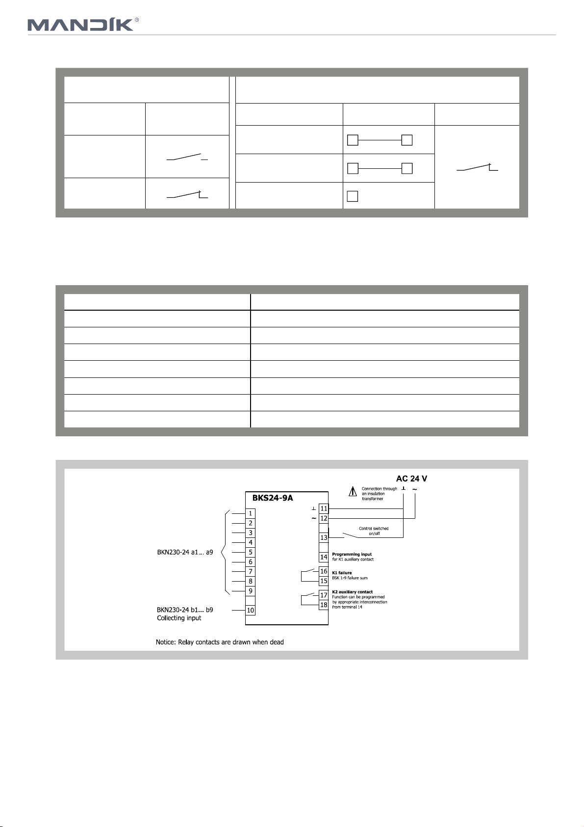
3.1. BKS 24-9A communication and control device is used for group control and checks of 1 to 9 fire
dampers with the actuating mechanism BFL 24-T-ST in connection with the supply and
communication device BKN 230-24. Signalisation of the damper position is individual; the
dampers can be controlled and tested only as a group. BKS 24-9A is intended for use in the
distribution board and displays the operation situations and failure reports of the connected fire
dampers. It is possible to signalise functions such as the damper position and failure reports or to
transmit them further to the system by means of integrated auxiliary switches. BKS 24-9A
receives signals from BKN 230-24 through the two-conductor wiring and issues control
commands. Proper damper operation is indicated by two light LED diodes:
Control ON = position OPERATION
Control OFF = position FAILURE
If the fire dampers do not reach the given position in time tolerable for displacing, the appropriate
light diode FAILURE starts to flash and K1 contact is opened (current failure). In case that the
faulty damper finally reaches its given position, K1 is closed and the failure report lights up shines
(the failure is saved in memory).
K2 - the auxiliary contact - is used for signalisation of the flap position to the master device. Function
of this auxiliary contact can be programmed through the terminal 14 according to the Tab. 3.1.1.
6
TPM 083/12
Tab. 3.1.1. BKS 24 -9A contacts K1 and K2
K1 Function Contact
Situation State
Current Failure
No Failure
15 16
15 16
Programming K2 Auxiliary Contact
Function
K2 contact is on if all the
damperss are open
K2 contact is on if the damper
No. 1 is open
K2 contact is on if all the
dampers are closed
Interconnection State
14 11
14 12
14 open
Function check can be done in the position OPERATION by means of pushing the TEST button.
While the button is pushed, the flap blade is turning into the position FAILURE. Fault function is
indicated by a report "FAILURE".
Tab. 3.1.2. Communication and Control Device BKS 24-9A
Communication and Control Device BKS 24-9A
Nominal voltage AC 24 V 50/60Hz
Power consumption 3,5 W (operating position)
Dimensioning 5,5 VA
Protection Class III (safe small voltage)
17 18
Degree of protection IP 30
Ambient Temperature 0 … + 50 °C
Connection Terminals for conductor 2 x 1,5 mm
Fig. 7 Communication and Control Device BKS 24-9A
2
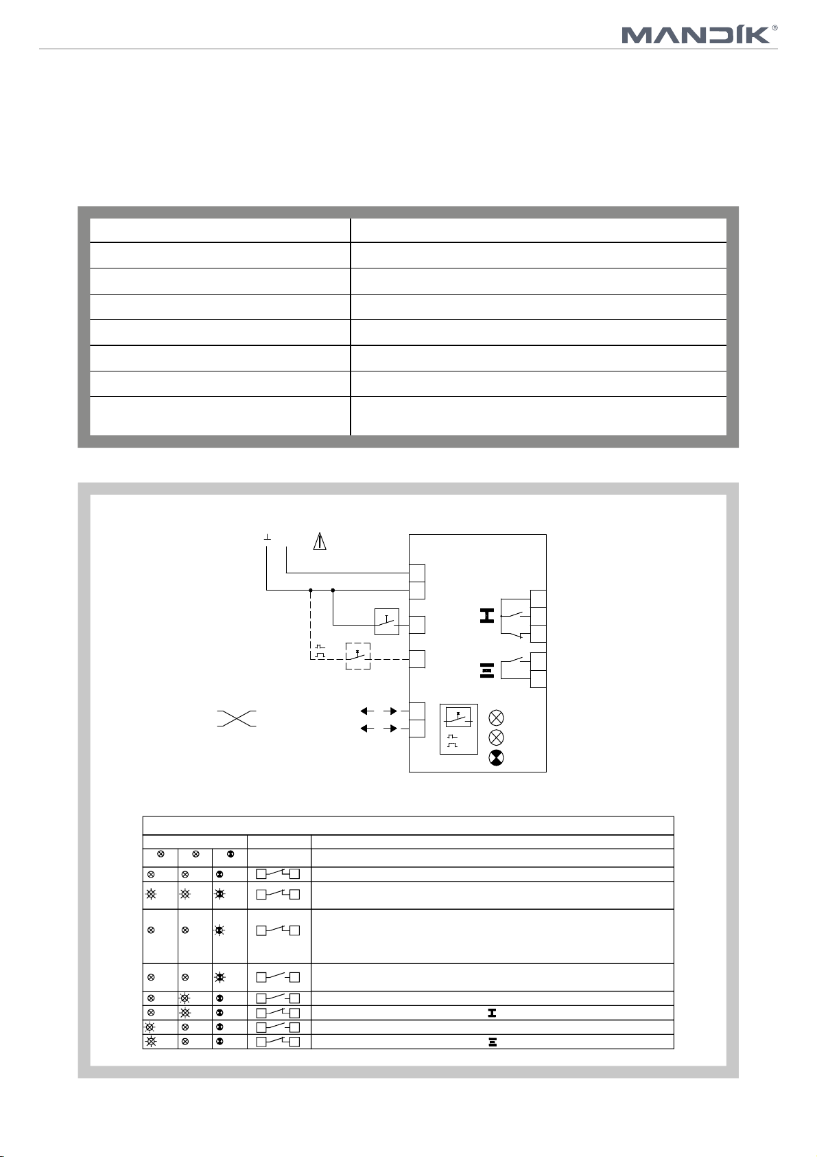
3.2. BKS 24-1B communication and control device is used for control and checks of fire dampers with
the BFL 24-T-ST actuating mechanism in conjunction with the BKN 230-24 supply and
communication device. BKS 24-1B receives information about the situation of the fire damper
through the BKN 230-24 supply and communication device and issues controlling commands.
The device is intended for building in into the distribution board. Light diodes on the front side of
the device indicates the operating situations of the damper and breakdowns of the whole system.
Nonpotential auxiliary contacts enable connection to the master control system (indication of the
damper position, failure reports, release of the ventilators etc.).
7
TPM 083/12
3.3. BKS 24-1B communication and control device is used for control and checks of fire dampers with
the BFL 24-T-ST actuating mechanism in conjunction with the BKN 230-24 supply and
communication device. BKS 24-1B receives information about the situation of the fire damper
through the BKN 230-24 supply and communication device and issues controlling commands.
The device is intended for building in into the distribution board. Light diodes on the front side of
the device indicates the operating situations of the damper and breakdowns of the whole system.
Tab. 3.3.1. Communication and Control Device BKS 24-1B
Communication and Control Device
BKS 24-1B
Nominal voltage AC 24 V 50/60Hz
Power consumption 2,5 W (operating position)
Dimensioning 5 VA
Protection Class III (safe small voltage)
Degree of protection IP 30
Ambient Temperature 0 … + 50 °C
Connection
Fig. 8 Communication and control device BKS 24-1B
Into ZSO-11 connector which is not a part of BKS 24-1B.
ZSO-11 connector has screw terminals 11 x 1,5 mm
AC 24 V
~
Connection through
an insulation
transformer
Control
switched
/off
on
Reset
Test
External buton
optional
10
BKS24-1B
2
AC
24V
1
5
6
damper position
4
breakdown
failure
3
damper position
7
operation
8
2
conection can
be interchanged
2-conductor wiring
to BKN230-24
Notice: Relay contacts are drawn
without power
Signals and diagnosis
light diodes contacts
open closed
closed
open
closed
closed
closed
closed
flashing
open
closed closed
open open
closed
closed
flashing
open
closed
closed
alarm
flashing
open
closed
closed
closed
closed
state
6
6 3
6
6
6 4
6
6 7
6
a
9
b
11
Power supply AC 24V
3
Check test cca 35sec
«Reset/Test» button
Current failure,
or damper failure (at BKN..) • Power supply AC 230V missing • defective
3
thermoelectrical starting • smoke detector activated • exceeded operation time
• damper blocked
Failure saved in memory
3
done
Damper (drive) turning into
Damper (drive) in
4
Damper (drive) turning into
Damper (drive) in
7
not available
, starting with switching AC 24 on or pressing
possible cause: • short circuit or interruption of 2-conductor wiring
breakdown position
operating position
Reset
Test
Description
Cause/Course
• Fault in system signalled, system check should be
the direction
the direction
open
closed
alarm
of breakdown position
of operating position
8
 Loading...