

Page 1
Page 2
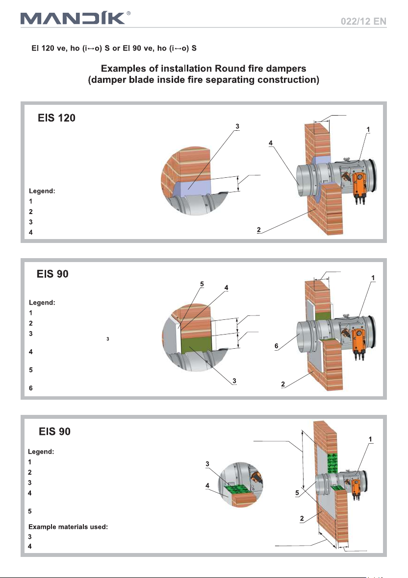
FIRE damper type FDMB, is in all variants classified:
≥ 100
≥ 40
≥ 100
≥ 100
as
EN 15650.
Installation in a solid wall construction
Fire damper FDMB
Solid wall construction
Mortar or gypsum
Duct
Installation in a solid wall construction
acc. EN 13501-3 and tested acc. EN 1366-2 and acc.
Fire damper FDMB
Solid wall construction
Stuffing box (mineral stone wool
min. density 140 kg/m )
Fire protection mastic
min. thickness 1 mm
Cement lime plate
min. thickness 15 mm
Duct
Installation in a solid wall construction (Weichschott system)
Fire damper FDMB
Solid wall construction
Fire protection plate of mineral wool
Fire protection mastic
min. thickness 1 mm
Duct
Hilti CP673 PF
Hilti CP673
≥ 50
≥ 40
D+60 to 800
max. 2050
D+60 to 800
max. 1650
1
Page 3

Installation in a gypsum wall construction
≥ 100
≥ 40
Stuffing box (mineral stone
wool min. density 140 kg/m )
Cement lime plate
min. thickness 15 mm
≥ 100
Fire protection plate of mineral wool
≥ 100
Fire damper FDMB
Mortar or gypsum
Fire protection plate of mineral wool
Gypsum wall construction
Duct
Installation in a gypsum wall construction
Fire damper FDMB
Gypsum wall construction
Fire protection plate of miner-
al wool
≥ 50
≥ 40
Installation opening perimeter
has to be reinforced by
standard drywall profiles.
Installation opening perimeter
has to be reinforced by
standard drywall profiles.
Fire protection mastic
min. thickness 1 mm
Duct
Installation in a gypsum wall construction (Weichschott system)
Fire damper FDMB
Gypsum wall construction
Fire resistant board
Fire protection mastic
min. thickness 1 mm
Duct
Hilti CP673 PF
Hilti CP673
2
D+60 to 800
max. 2050
D+60 to 800
max. 1650
Installation opening perimeter
has to be reinforced by
standard drywall profiles.
Page 4
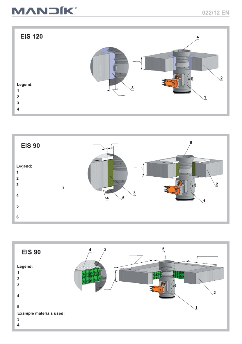
Installation in a solid ceiling construction
≥ 40
150*
150*
Stuffing box (mineral stone wool
min. density 140 kg/m )
Cement lime plate
min. thickness 15 mm
≥ 40
≥ 50
150*
* min. 110 - Concrete/ min. 125 - Aerated Concrete
Fire damper FDMB
Solid ceiling construction
Mortar or gypsum
Duct
Installation in a solid ceiling construction
Fire damper FDMB
Solid ceiling construction
* min. 110 - Concrete/ min. 125 - Aerated Concrete
Fire protection mastic
min. thickness 1 mm
Duct
Installation in a solid ceiling construction (Weichschott system)
Fire damper FDMB
Solid ceiling construction
Fire protection plate of
mineral wool
Fire protection mastic
min. thickness 1 mm
Duct
Hilti CP673 PF
Hilti CP673
D+60 to 800
max. 1650
3
* min. 110 - Concrete/ min. 125 - Aerated Concrete
D+60 to 800
max. 2050
Page 5
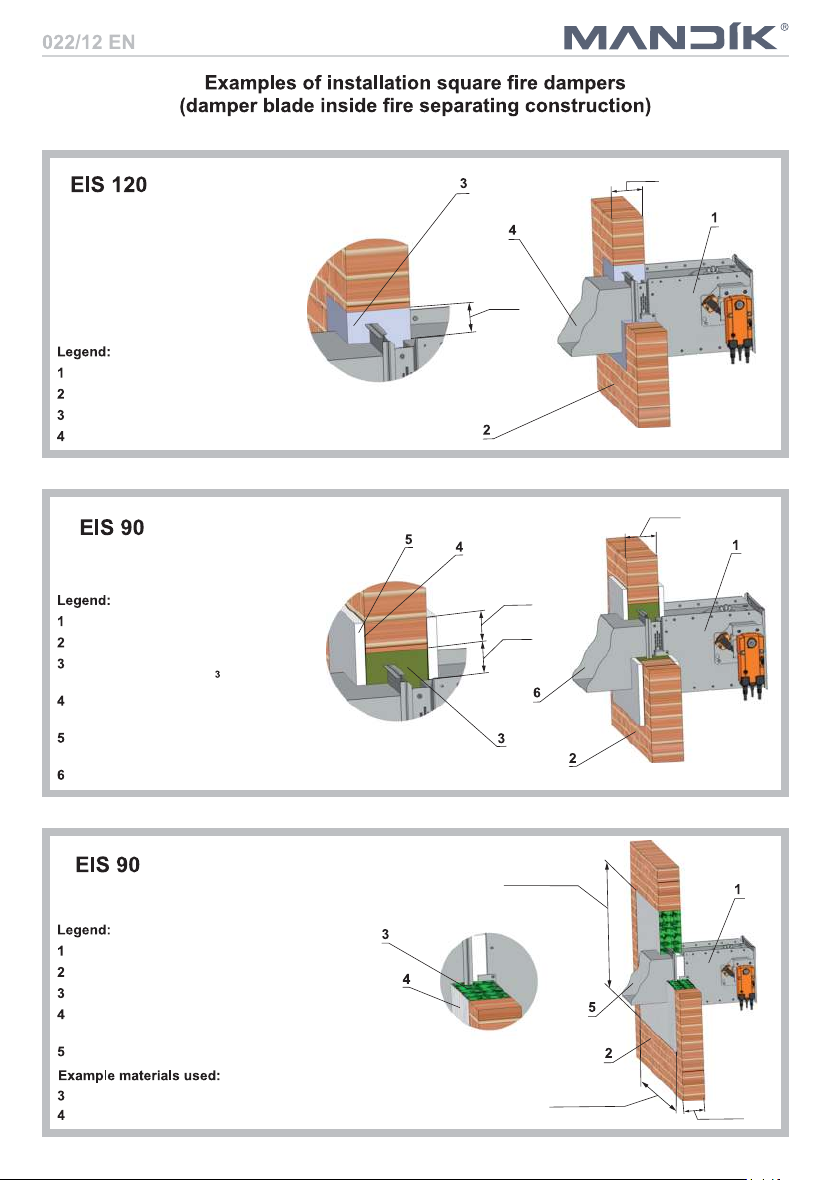
Installation in a solid wall construction
≥ 100
≥ 50*
≥ 100
≥ 50*
≥ 50*
* Around the perimeter
≥ 100
Fire protection plate of mineral wool
Fire damper FDMB
Solid wall construction
Mortar or gypsum
Duct
Installation in a solid wall construction
Fire damper FDMB
Solid wall construction
Stuffing box (mineral stone wool
min. density 140 kg/m )
Fire protection mastic
min. thickness 1 mm
Cement lime plate
min. thickness 15 mm
Duct
* Around the perimeter
Installation in a solid wall construction (Weichschott system)
Fire damper FDMB
Solid wall construction
Fire protection mastic
min. thickness 1 mm
Duct
Hilti CP673 PF
Hilti CP673
B+60 to 800
max. 2050
A+60 to 800
max. 1650
4
Page 6
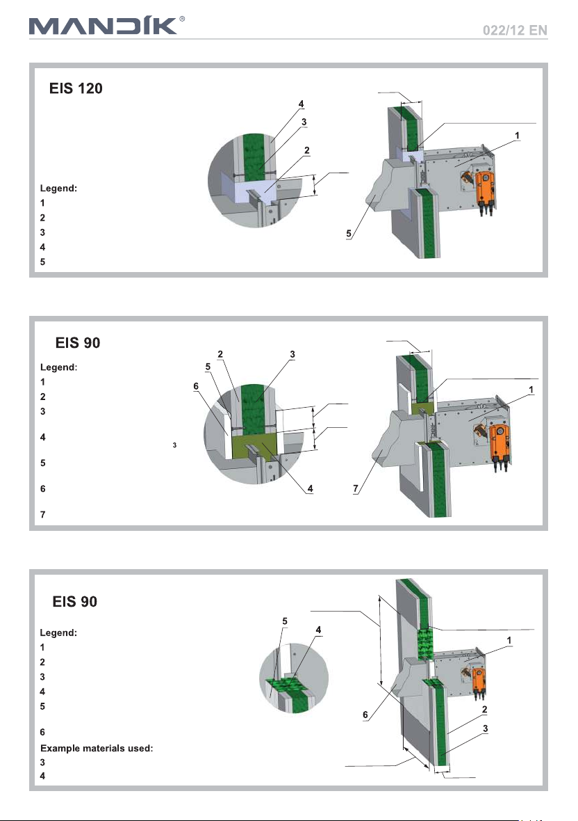
Installation in a gypsum wall construction
≥ 100
≥ 50*
* Around the perimeter
≥ 100
≥ 50*
≥ 50*
Stuffing box (mineral stone
wool min. density 140 kg/m )
Cement lime plate
min. thickness 15 mm
* Around the perimeter
≥ 100
Fire damper FDMB
Mortar or gypsum
Fire protection plate of mineral wool
Gypsum wall construction
Duct
Installation in a gypsum wall construction
Fire damper FDMB
Gypsum wall construction
Fire protection plate of
mineral wool
Installation opening perimeter
has to be reinforced by
standard drywall profiles.
Installation opening perimeter
has to be reinforced by
standard drywall profiles.
Fire protection mastic
min. thickness 1 mm
Duct
Installation in a gypsum wall construction (Weichschott system)
Fire damper FDMB
Gypsum wall construction
Fire resistant board
Fire protection plate of mineral wool
Fire protection mastic
min. thickness 1 mm
Duct
Hilti CP673 PF
Hilti CP673
5
B+60 to 800
max. 2050
A+60 to 800
max. 1650
Installation opening perimeter
has to be reinforced by
standard drywall profiles.
Page 7
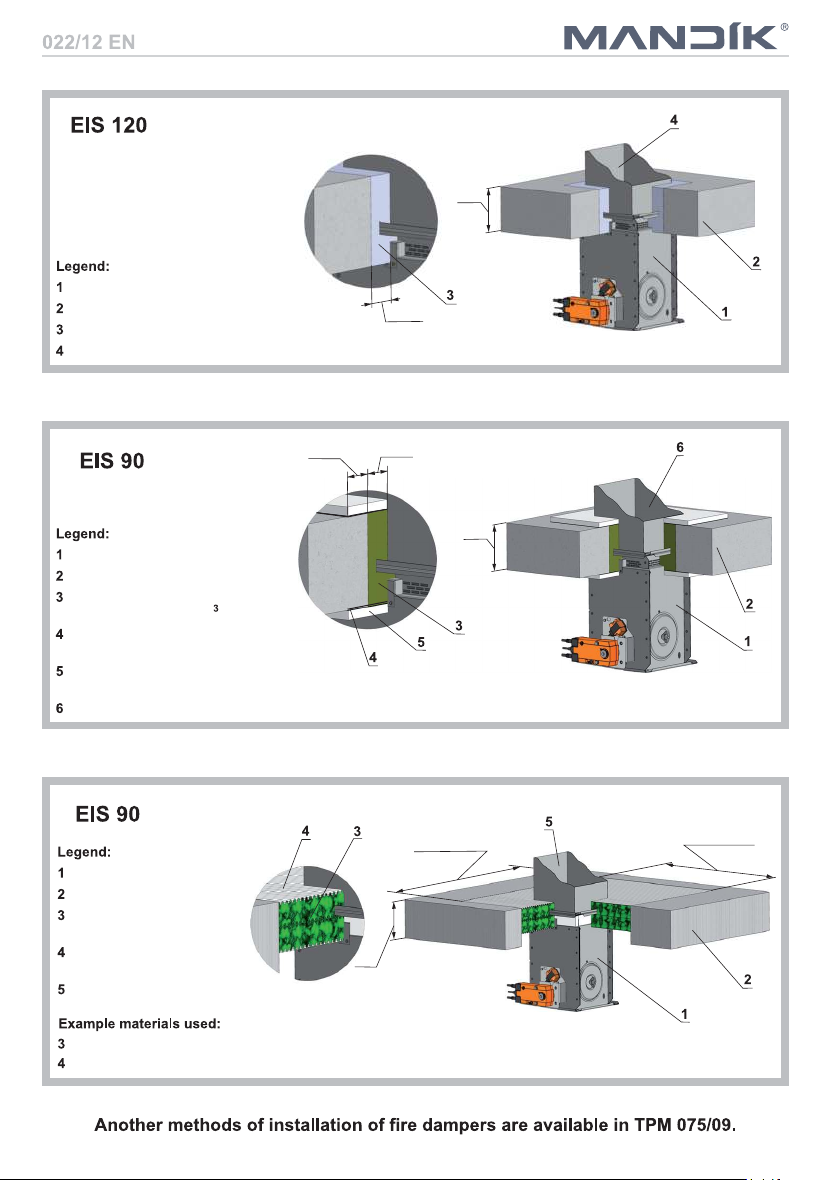
Installation in a solid ceiling construction
≥ 50**
150*
** Around the perimeter
150*
≥ 50**
≥ 50**
Cement lime plate
min. thickness 15 mm
** Around the perimeter
150*
* min. 110 - Concrete/ min. 125 - Aerated Concrete
Fire damper FDMB
Solid ceiling construction
Mortar or gypsum
Duct
Installation in a solid ceiling construction
Fire damper FDMB
Solid ceiling construction
Stuffing box (mineral stone wool
min. density 140 kg/m )
Fire protection mastic
min. thickness 1 mm
* min. 110 - Concrete/ min. 125 - Aerated Concrete
Duct
* min. 110 - Concrete/ min. 125 - Aerated Concrete
Installation in a solid ceiling construction (Weichschott system)
Fire damper FDMB
Solid ceiling construction
Fire protection plate of
mineral wool
Fire protection mastic
min. thickness 1 mm
Duct
Hilti CP673 PF
Hilti CP673
B+60 to 800
max. 1650
6
A+60 to 800
max. 2050
Page 8
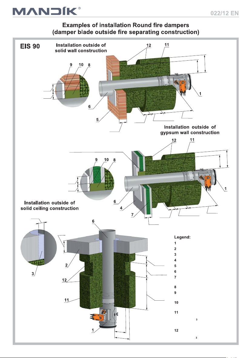
≥ 100
≥ 400
≥ 100
Installation opening perimeter has to be
≥ 100
≥ 400
≥ 100
≥ 100
≥ 400
variable **
≥ 50
≥ 50
≥ 50
≥ 50
* min. 110 - Concrete/ min. 125 - Aerated Concrete
150*
≥ 40
Stone wool with one side stitched
on wire Grids, bulk density
105 kg/m thick. 180 mm (e.g.,
three layers thick. 60 mm)
Stone wool with one side stitched
on wire Grids, bulk density
105 kg/m thick. 60 mm
reinforced by standard drywall profiles.
variable **
variable **
240
180
240
180
** Dependent on the distance between
damper and fire separating construction
180
240
Fire damper FDMB
Solid ceiling construction
Mortar or gypsum
Gypsum wall construction
Solid wall construction
Duct
Fire protection plate of mineral
wool
Mineral stone wool
Fire protection mastic min. thick-
ness 1 mm
Cement lime plate min. thickness
15 mm
7
Page 9
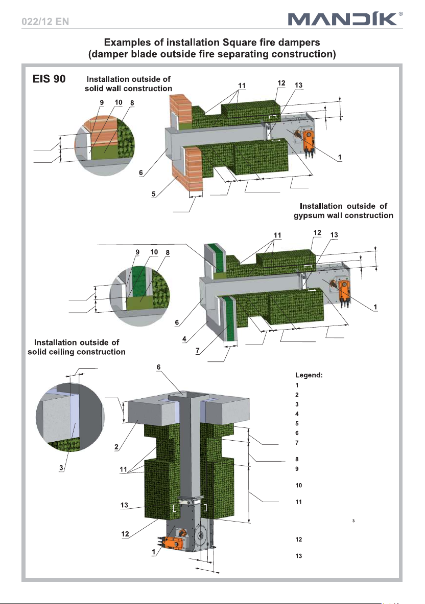
≥ 400
≥ 100
≥ 400
≥ 400
≥ 100
* min. 110 - Concrete/ min. 125 - Aerated Concrete
≥ 100
≥ 100
150*
≥ 50***
Installation opening perimeter has to be
≥ 100
≥ 50***
≥ 50***
≥ 50***
≥ 50***
reinforced by standard drywall profiles.
*** Around the perimeter
** Dependent on the distance between
damper and fire separating
120
60
variable **
120
60
variable **
Fire damper FDMB
Solid ceiling construction
Mortar or gypsum
Gypsum wall construction
Solid wall construction
Duct
Fire protection plate
variable **
60
120
**** Detail mounting and placementVRM-III page 12
of mineral wool
Mineral stone wool
Fire protection mastic
min. thickness 1 mm
Cement lime plate
min. thickness 15 mm
Stone wool resin bonded con-
taining toxic rubble as refrigerants, fire resistance EIS 90 min.
density 300 kg/m
th. 60 mm and 120 mm
Sheet metal a stiffener
U25x40x25
VRM-III****
8
Page 10
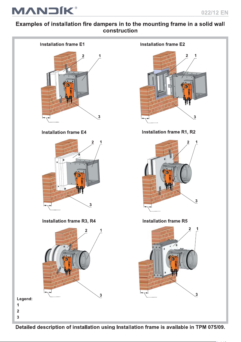
≥ 100
≥ 100
≥ 100
Fire damper FDMB
≥ 100
≥ 100
≥ 100
Installation frame
Solid wall construction
9
Page 11
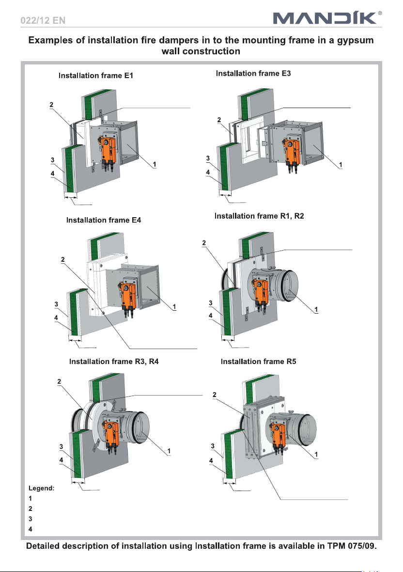
≥ 100
≥ 100
≥ 100
Installation opening perimeter
≥ 100
≥ 100
≥ 100
has to be reinforced by
standard drywall profiles.
Installation opening perimeter
has to be reinforced by
standard drywall profiles.
Installation opening perimeter
has to be reinforced by
standard drywall profiles.
Installation opening perimeter
has to be reinforced by
standard drywall profiles.
Installation opening perimeter
has to be reinforced by
standard drywall profiles.
Fire damper FDMB
Installation frame
Gypsum wall construction
Fire protection plate of mineral wool
Installation opening perimeter
has to be reinforced by
standard drywall profiles.
10
Page 12
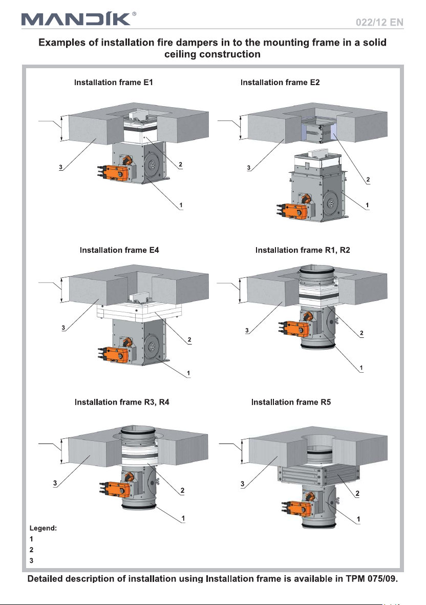
* min. 110 - Concrete/ min. 125 - Aerated Concrete
150*
150*
150*
150*
Fire damper FDMB
Installation frame
Solid ceiling construction
150*
150*
11
Page 13
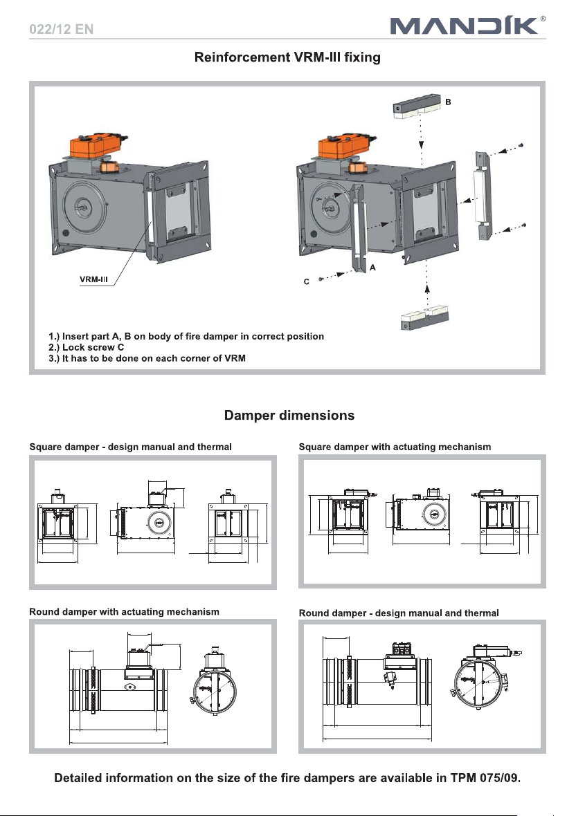
Notice: For installation outside of fire separating construction has to be used reinforcement VRM- III fixing.
123
110
B
B+60
A
A+60
375
B-X*
B+60
A-X*
A+60
(60+X)/2
(60+X)/2
B
B+60
A
A+60
375
B-X*
B+60
A-X*
A+60
(60+X)/2
(60+X)/2
475
115
375 5050
Ø
D
375 5050
Ø
D
475
115
110
125
* X=23 (AxB≤500x400)
* X=36 (AxB>500x400)
* X=23 (AxB≤500x400)
* X=36 (AxB>500x400)
12
Page 14
1. All fire dampers has to be closed during installation process.
2. The control mechanism has to be protected (covered) against damage and pollution during installation
process.
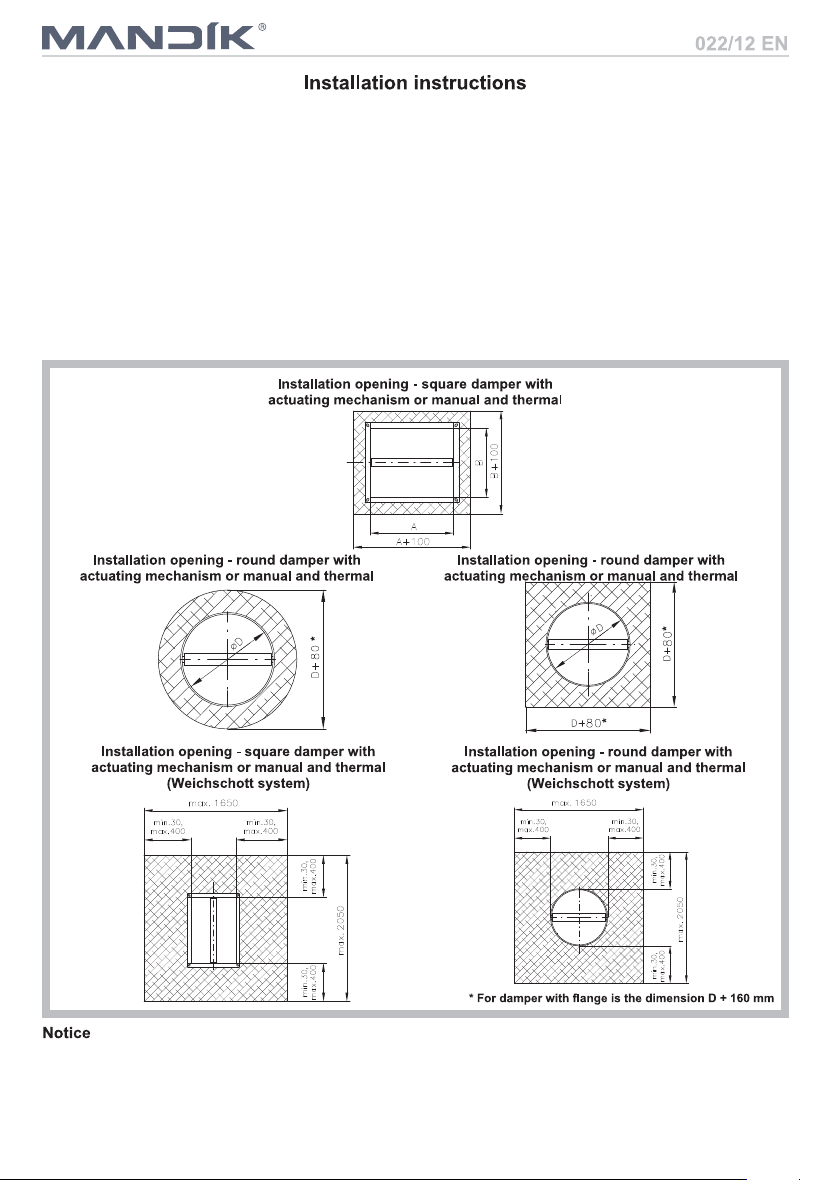
3. Min. gap for installation (installation opening) is 25 mm (circular dimension Ø D + 50 mm or square
dimension AxB + 100 mm).
4. Installation gap must be filled by approved material perfectly in all the installation space volume
(installation gap).
5. The distance between the fire damper and the construction (wall, ceiling) must be minimum 75 mm
according to EN 1366-2. In case that two or more dampers are supposed to be installed in one fire
separating construction, the distance between the adjacent dampers must be at least 200 mm according
to EN 1366-2 paragraph 13.5.
6. Installation openings
Fire dampers are suitable for installation in arbitrary position in vertical and horizontal passages of fire
separating constructions. Damper assembly procedures must be done so as all load transfer from the fire
separating constructions to the damper body is absolutely excluded. Back-to-back air-conditioning piping
must be hung or supported so as all load transfer from the back-to-back piping to the damper is absolutely
excluded.
13
Page 15
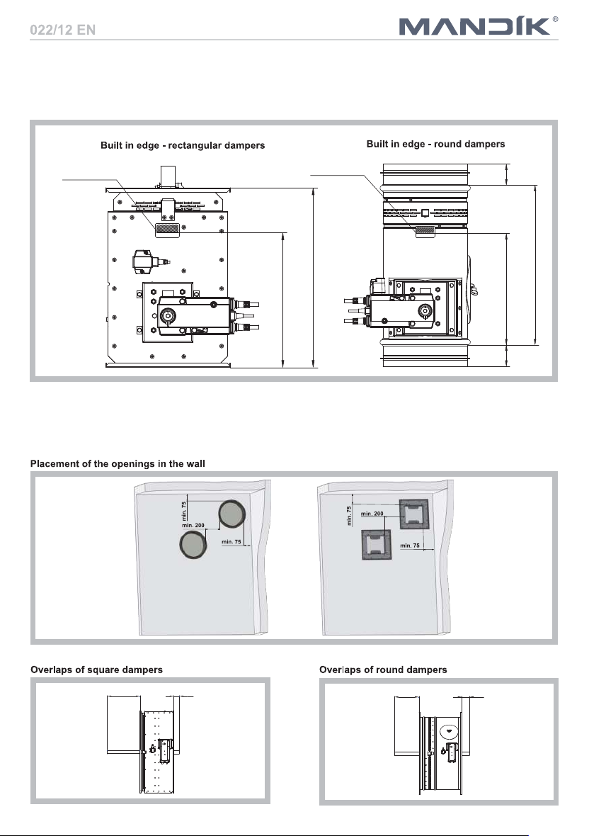
7. The fire damper can be integrated into a solid or gypsum wall construction or into solid ceiling
c a
c a
375
280
375
260 5050
construction. Damper blade has to be inside of construction (labelled BUILD IN EDGE on the damper
body). The fire damper can also be integrated outside the wall construction. Duct and the damper part
between the wall construction and the damper blade (labelled BUILD IN EDGE on the damper body)
must be protected with fire-fighting insulation.
Built in edge
Built in edge
8. All fire dampers has to be closed during installation process. The damper body should not be deformed
in the course of bricking in. Once the damper is built in, its blade should not grind on the damper body
during opening or closing.
9. To provide needed access space to the control device, all other objects must be situated at least 350
mm from the control parts of the damper. Inspection hole must be accessible.
10. Damper blade overlaps
14
Page 16
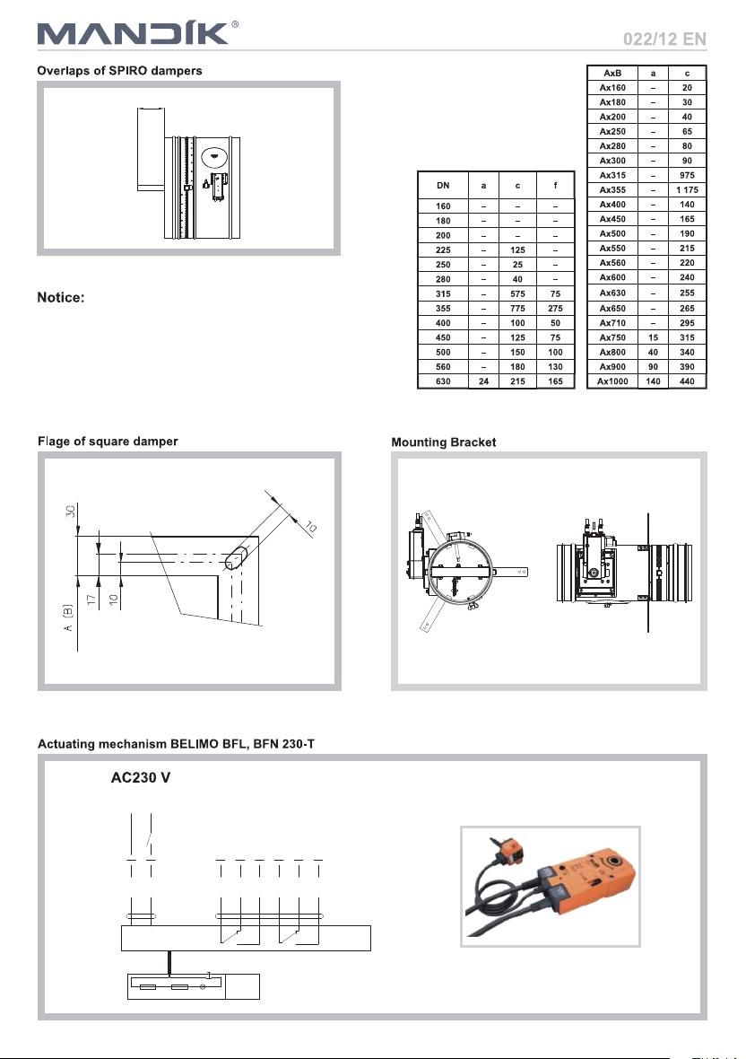
The blade of fire damper exceeds body
1
2
S3S1S2
S5S4
S6
N
L1
<5°
<80°
BAT
Tf
Tf
LED
f
of fire damper by the value “a” and “c” or “e”
and “f”. There has to be enough space in duct
for blade rotation. Values "a" and "c" or "e" and
"f" has to be respected when projecting related
air-conditioning ducts.
11. Flanges and Bracket
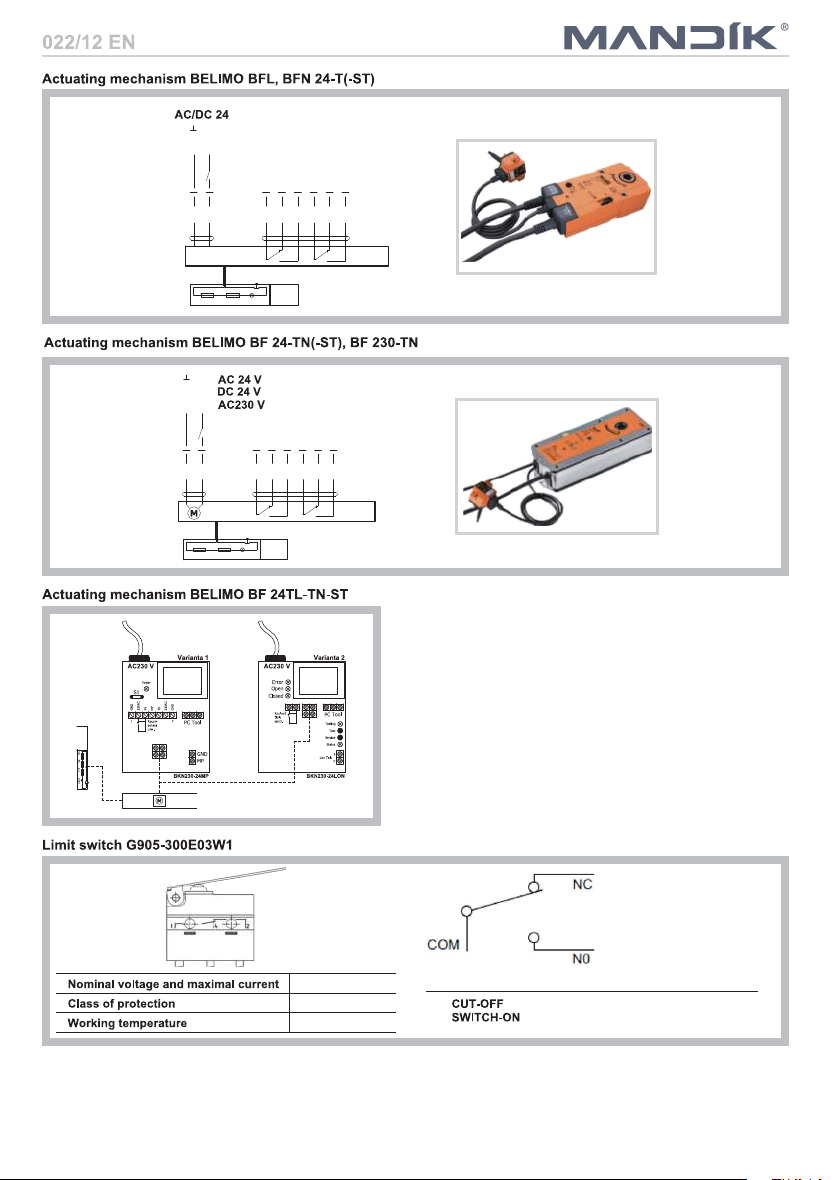
12. Electrical components, wiring diagrams
15
Page 17
1
2
S3S1S2
S5S4
S6
<5°
<80°
BAT
Tf
Tf
LED
~
- +
1
2
S3S1S2
S5S4
S6
N
L1
~
- +
<5°
<80°
BAT
Tf
Tf
LED
-25°C … +120°C
BAT
AC 230V / 5A
IP 67
1(COM) - black wire
2(NC) -
gray wire
4(NO) - blue wire
This limit switch is possible to connect in following two versions:
a)
b)
if the arm is moving … connect wire 1+2
if the arm is moving … connect wire 1+4
13. Before entering the dampers into operation after assembly and after sequential revisions, checks and
functionality tests of all designs including operation of the electrical components must be done. After
entering into operation, these revisions must be done according to requirement set by national
regulations.
16
Page 18

14. Before entering the dampers into operation after their assembly and by sequential checks, the following
checks must be carried out for all designs.
Visual inspection of proper damper integration, inside damper area, damper blade, contact surfaces
and silicon sealing.
Inspection hole disassembly: release the covering lid by turning the wing nut and while turning the lid
right or left release it from the security belt. Then tilt the lid and remove it from its original position.
15. Before entering the dampers with manual control into operation after their assembly and by sequential
checks, checks according 14. and following checks must be carried out.
Check of thermal protective fuse and closing mechanism.
Exert pressure on double arm initiation lever with a spring to release the control lever and check its
displacement into the "CLOSED" position. Closing must be smart and the control lever must be firmly
locked with a pawl. In case that the closing is not smart enough and the control lever is not locked with
the pawl in the "CLOSED" position, higher pre-stretch of the closing spring must be set using a ratchet
wheel.
Proper function of the thermal fuse can be checked when the fuse is removed from the starting
mechanism. The initiation lever must be turned over and control lever is moved to position "CLOSED".
If this is not possible, then the starting mechanism spring must be checked or the base plate must be
replaced. The base plate is attached to the damper body with M5 screws.
Displacing the damper blade into "OPEN" position is done the following way:
Release the pawl exerting pressure and return the control lever into the second outlaying position where
the lever is hold by the initiation lever.
16. Before entering the dampers with actuating mechanism into operation after their assembly and by
sequential checks, checks according 14. and following checks must be carried out.
Check of blade displacement into the breakdown position "CLOSED" can be done after cutting off the
actuating mechanism supply (e.g. by pressing the RESET button at the thermoelectrical starting
mechanism BAT or cutting off the supply from ELECTRICAL FIRE SIGNALISATION). Check of blade
displacement back into the "OPEN" position can be done after restoration of power supply (e.g. By
releasing the RESET button or restoration of supply from ELECTRICAL FIRE SIGNALISATION).
17. Manual operation
Without power supply, the damper can be operated manually and fixed in any required position.
Release of the locking mechanism can be achieved manually or automatically by applying the supply
voltage.
18. It is recommended to provide periodical checks, maintenance and service actions on Fire Equipment
by Authorized persons schooled by Producer.
20. All effective safety standards and directives must be observed during fire damper assembly.
17
Page 19

1. Damper bodies are supplied in the standard design made of galvanized plate without any other surface
finish.
2. Damper blades are made of fire resistant asbestos free boards made of mineral fibres.
3. Damper controls are made of galvanized materials with no other surface finish.
4. Springs are galvanized.
5. Thermal protective fuses are made of sheet brass, thickness = 0.5 mm.
6. Fasteners is galvanized.
18
Page 20

MANDÍK, a.s.
Dobříšská 550
26724 Hostomice
Czech Republic
Tel.: +420 311 706 706
E-Mail: [email protected]
www.mandik.com
19
 Loading...