


1
1. Description.........................................................................................................................
2
2. Damper Design..….............................................................................................................
3
3. Dimensions, weights...........................................................................................................
4
4. Placement and Assembly....................................................................................................
5
5. Statement of installations....................................................................................................
7
6. Pressure loss and noise data..............................….............................................................
13
7. Coefficient of local pressure loss.......................................................................................
14
8. Material............................................................................................................................. 15
9 Inspection, testing............................................................................................................. 15
15
10. Logistic terms....................................................................................................................
15
11. Assembly..........................................................................................................................
15
12. Entry into service and revisions.........................................................................................
16
13. Data label..........................................................................................................................
16
14 Quick review.....................................................................................................................
16
17
15. Ordering key.................................................................................................................….
17
These technical specifications state a row of manufactured sizes and models of fire dampers (further only dampers)
CFDM. It is valid for production, designing, ordering, delivery, assembly and operation.
2
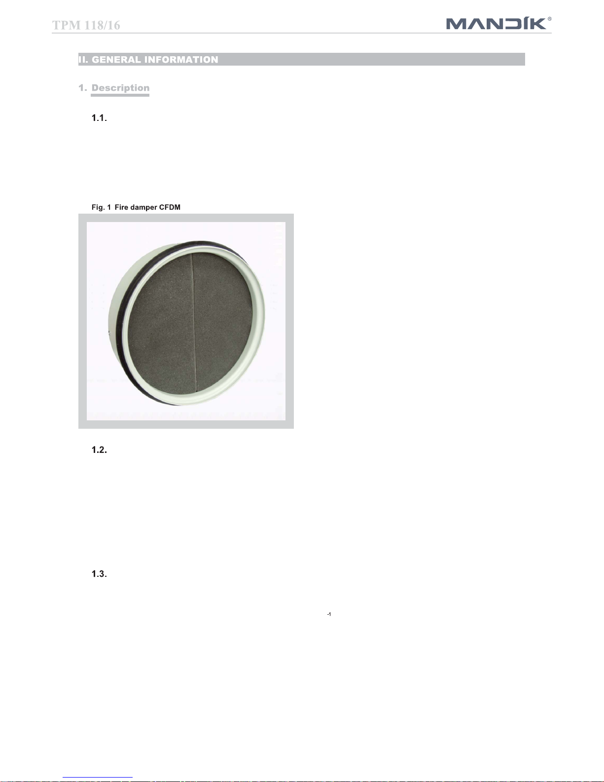
Fire dampers are shutters in duct systems of air-conditioning devices that prevent spreading the
fire and combustion products from one fire segment to the other one by means of closing the air
duct in the points of fire separating constructions.
Dampers blade automatically closes air duct using a shutting spring.
The damper is sealed with a plastic foam packing against smoke penetration after closing the
blade. At the same time, the damper blade is bedded in a material which enlarges its capacity
and air´proofs the air duct.
Damper characteristics
• CE certified acc. to EN 15650
• Tested in accordance with EN 1366-2
• Classified acc. to EN 13501-3+A1
• Fire resistance EIS 120, EIS 90, EIS 60
• Internal leakage class 2 acc. to EN 1751, external leakage is equal to ducting system
• Corrosion resistant acc. to EN 15650
• ES Certificate No. 1391-CPR-2016/0082
• Declaration of Perfomance No. PM/CFDM/01/16/1
Working conditions
Exact damper function is provided under the following conditions:
a) Maximum air circulation speed: 12 m.s
Maximum pressure difference: 1500 Pa
b) The air circulation in the whole damper section must be secured as steady on whole
surface.
Operation of the damper does not depend on the direction of air circulation. The dampers can
be located in an arbitrary position.
Dampers are suitable for ventilation systems, where air does not content any abrasive, chemical
or adhesive particles.
3
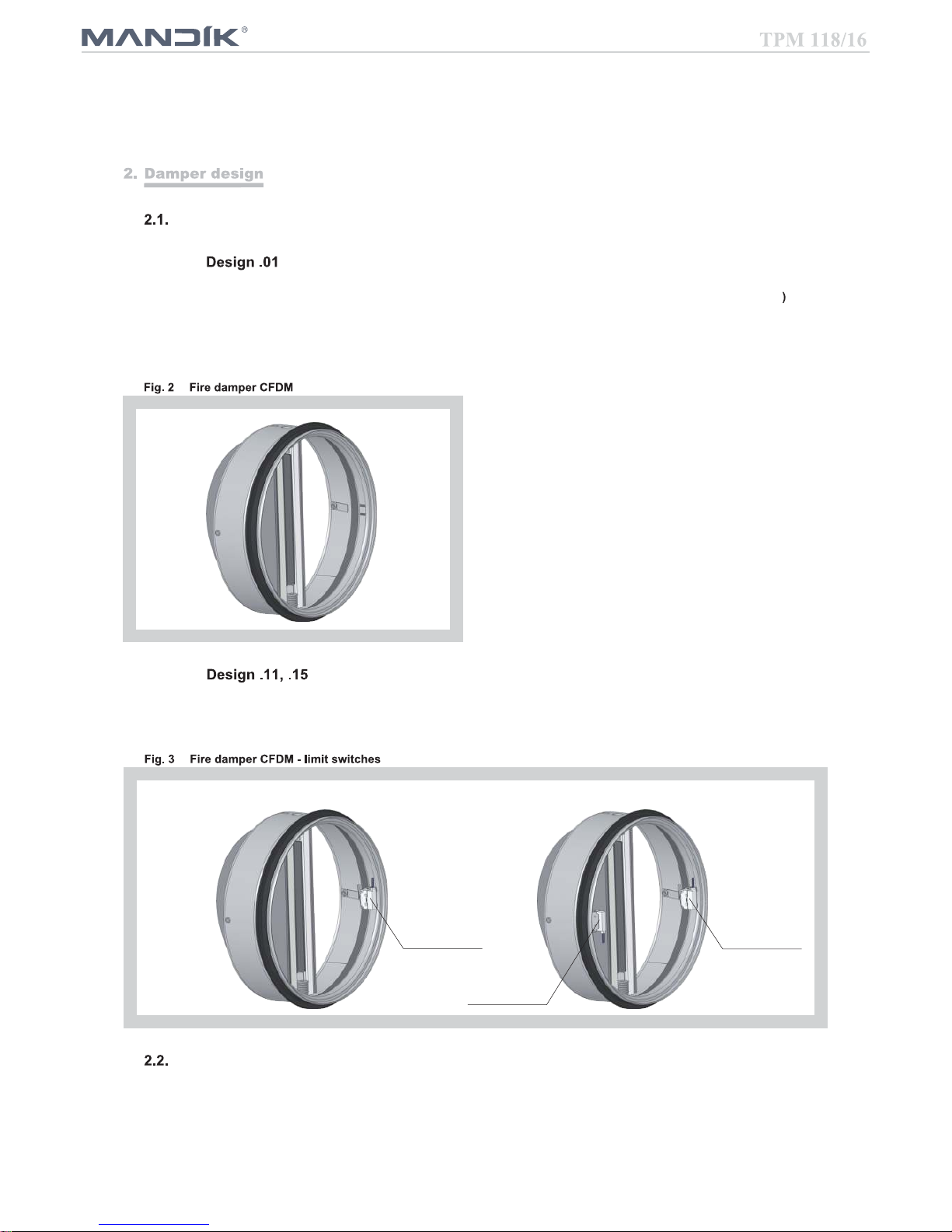
Design .01 with mechanical control can be equipped by one or two limit switches signalling
position of the damper blade "CLOSED". Limit switch is connected via duct.
Design .11 Design .15
Limit switch
“CLOSED”
Limit switch
“CLOSED”
Limit switch
“CLOSED”
Design according to fire resistance
● EIS 120
● EIS 90
● EIS 60
Dampers are designed for macroclimatic areas with mild climate according to EN 60 721-3-3.
Temperature in the place of installation is permitted to range from - 20°C to + 50°C.
Design with mechanical control
Design with mechanical control with a thermal protective fuse (inner mechanical control which
actuates the shutting device within 120 seconds at latest after the nominal start temperature
72 °C has been reached. Automatic initiation of the shutting device is not activated if the
temperature does not exceed 70 °C.
4
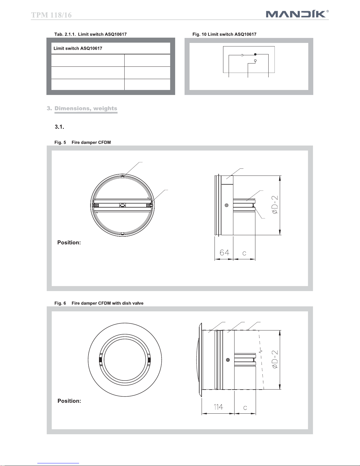
Dimensions
1 Damper casing
2 Damper blade
3 Shutting spring
4 Thermal fuse
5 Locking planchet
1 Fire damper CFDM
2 Dish valve
3 Duct
COM
black
NO
red
NC
white
Nominal voltage, current DC 30 V; 0,1 A
Degree of protection IP 67
Ambient temperature -40 °C … 85 °C
1
2
4
3
5
12 3
5
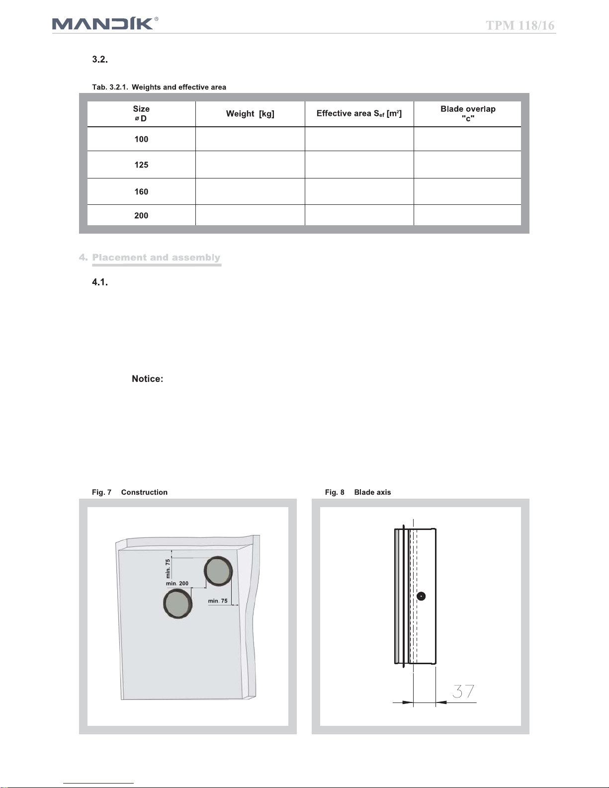
Weights and effective area
0,3 0,0027 15,5
0,4 0,0056 28
0,55 0,0115 45,5
0,75 0,0206 72,5
Fire dampers are suitable for installation in arbitrary position in vertical and horizontal passages
of fire separating constructions. Duct assembly procedures must be done so as all load transfer
from the fire separating constructions to the duct in the placement of fire damper installation is
absolutely excluded. Installation gap must be filled by approved material perfectly in all the
installation space volume (installation gap).
To provide needed access space to the control device, all other objects must be situated at least
350 mm from the control parts of the damper. Inspection hole must be accessible.
Damper has to be accessible for regular checks and maintenance.
Fire damper is inserted inside the duct. Blade has to be inside of fire separating
construction (after closing).
The distance between the fire damper and the construction (wall, ceiling) must be at least 75 mm.
In case that two or more dampers are supposed to be installed in one fire separating construction,
the distance between the adjacent dampers must be at least 200 mm according to EN 1366-2
paragraph 13.5.

6
Installation opening dimensions (see Fig. 9-11)
Examples of fire damper installing
The fire damper can be integrated into a solid wall construction made e.g. of normal concrete/
masonry, porous concrete with minimum thickness 100 mm or into solid ceiling construction made
e.g. of normal concrete with minimum thickness 110 mm or porous concrete with minimum
thickness 125 mm.
The fire damper can be integrated into a gypsum wall construction with fire classification
EI 120 or EI 90.

7
Wet mortar or gypsum 12
Dry
mineral wool boards with fire resistant
coating
13
Wet mortar or gypsum 14
Dry
mineral wool boards with fire resistant
coating
15
Wet mortar or gypsum 16
Dry
mineral wool boards with fire resistant
coating
17
Statement of installations the fire dampers CFDM
25
≥ 100
Position:
1 Fire damper CFDM
2 Solid wall construction
3 Mortar or gypsum
4 Duct
Make installation
Opening
Install duct in
the Opening
Fill gap Insert damper
in the duct

8
≥ 100
Position:
1 Fire damper CFDM
2 Solid wall construction
3
Fire resistant board
4
Fire stop coating thickness 1 mm
5 Glass fiber felt with aluminium foil width
50 mm, thickness 5 mm
6 Duct
Used materials - example*:
3 - Hilti CFS-CT B 1S 140/50
4 - Hilti CFS-CT
* Fire resistant board and fire stop coating can be
replaced by another approved fire sealing system for
damper installation with equivalent material properties.
D+60 to 800
max. 1650
D+60 to 800
max. 2050
Make installation
Opening
Install duct in
the Opening
Fill gap and cover
duct by fire resistant
coating
Insert damper
in the duct
≥ 50
≥ 50

9
25
≥ 100
Position:
1 Fire damper CFDM
2 Solid wall construction
3 Mortar or gypsum
4 Duct
Installation opening has to be reinforced by
profile (UW, CW). Profil is fixed by screws
≥3,5 mm with corresponding length.
Distance between screws ≤200 mm.
Make installation
Opening
Install duct in
the Opening
Fill gap
Insert damper
in the duct

10
≥ 100
* Fire resistant board and fire stop coating can be
replaced by another approved fire sealing system for
damper installation with equivalent material properties.
D+60 to 800
max. 1650
D+60 to 800
max. 2050
Installation opening has to be reinforced by
profile (UW, CW). Profil is fixed by screws
≥3,5 mm with corresponding length.
Distance between screws ≤200 mm.
Make installation
Opening
Install duct in
the Opening
Fill gap and cover
duct by fire resistant
coating
Insert damper
in the duct
Position:
1 Fire damper CFDM
2 Gypsum wall construction
3
Fire resistant board
4
Fire stop coating thickness 1 mm
5 Glass fiber felt with aluminium foil width
50 mm, thickness 5 mm
6 Duct
Used materials - example*:
3 - Hilti CFS-CT B 1S 140/50
4 - Hilti CFS-CT
≥ 50
≥ 50

11
Position:
1 Fire damper CFDM
2 Solid wall construction
3 Mortar or gypsum
4 Duct
≥ 25
150*
Install duct in
the Opening
Insert damper
in the duct
Make installation
Opening
Fill gap
* min. 110 - Concrete/ min. 125 - Aerated concrete

12
150*
* min. 110 - Concrete/ min. 125 - Aerated concrete
* Fire resistant board and fire stop coating can be
replaced by another approved fire sealing system for
damper installation with equivalent material properties.
D+60 to 800
max. 2050
D+60 to 800
max. 1650
Make installation
Opening
Install duct in
the Opening
Fill gap and cover
duct by fire resistant
coating
Insert damper
in the duct
Position:
1 Fire damper CFDM
2 Ceiling wall construction
3
Fire resistant board
4
Fire stop coating thickness 1 mm
5 Glass fiber felt with aluminium foil width
50 mm, thickness 5 mm
6 Duct
Used materials - example*:
3 - Hilti CFS-CT B 1S 140/50
4 - Hilti CFS-CT
≥ 50
≥ 50

13
Install duct together with
construction edge
Insert damper in distance 50
mm from the edge in the duct
50
Insert valve housing in the duct
and screw to the construction
Insert valve in the housing
Pressure loss calculation
p
=
w
2
p [Pa] pressure loss
w [m.s ] air flow speed in nominal damper section
[kg.m ] air density
[-] coefficient of local pressure loss for the nominal damper section
(see Tab. 7.1.1.)

14
1,836 1,083 0,7407 0,4167
Given data Fire damper CFDM 200
V = 600 m .h
= 1,2 kg.m
Tab. 3.2.1. Sef = 0,0206 m
Calculation:
w [m.s ] = (V [m .h ] / 3600) / Sef [m ]
w = 8,09 m.s
Tab. 7.1.1. =
0,4167
Calculation: p = . . (w /2) = 0,4167 . 1,2 . (8,09 /2) = 16,4 Pa
Diagram 6.2.1. LWA =
52 dB
Determination of pressure loss by using diagram 9.2.1. = 1,2 kg.m and noise data
Coefficient of local pressure loss (-)

15
Damper casing are supplied in the design made of galvanized sheet without any other surface
finishing.
Damper blades are made of fire resistant asbestos free boards made of mineral fibres.
Damper controls are made of stainless steel with no other surface finish.
Springs are made of stainless steel.
Thermal protective fuses are made of sheet brass, thickness = 0,5 mm.
Fasteners are galvanized.
According to the customer's requirements damper casing can be finished by color acc. RAL.
The appliance is constructed and preset by the manufacturer, its operation is dependent on
proper installation and adjustment.
Dampers are transported by box freight vehicles without direct weather impact, there must not
occur any sharp shocks and ambient temperature must not exceed + 40 °C. Dampers must be
protected against mechanic damages when transported and manipulated. During transportation,
the damper blade must be in the "CLOSED" position.
Dampers are stored indoor in environment without any aggressive vapours, gases or dust. Indoor
temperature must be in the range from -5 °C to +40 °C and maximum relative humidity 80 %.
Dampers must be protected against mechanic damages when transported and manipulated.
All effective safety standards and directives must be observed during fire damper assembly.
To ensure reliable fire damper function it is necessary to avoid blocking the closing mechanism
and contact surfaces with collected dust, fibre and sticky materials and solvents.
Before entering the dampers into operation after their assembly and by sequential checks, the
following checks must be carried out.
Visual inspection of proper damper integration, inside damper area, damper blade, contact
surfaces and silicon sealing.

16
It is recommended to provide periodical checks, maintenance and service actions on Fire
Equipment by Authorized persons schooled by Producer.
Data label is placed on the casing of fire damper.
EI90 (ve, ho-i o)S
Dobříšská 550
267 24 Hostomice
MANDÍK, a.s.
Czech Republic
1391
Požární klapka / Fire damper /
Klasifikace / Classification / Feuerwiederstand / Classification
Rozměr / Size / Grösse / Taille
Výr. číslo / Serial number / Fert. Nr. / Numéro de serie
SAMPLE
Provedení / Design / Ausführung / Conception
.01
Certifikace / Certificate / Zulassungs-Nr. / Certifikat
Hmotnost / Weight / Gewicht / Poids
1391-CPD-2016/0082
16
200
0,5
EN 15650:2010
TPM 118/16
Brandschutzklappe / Clapet coupe-feu
100 Mortar or gypsum
EIS 120
EIS 90
EIS 60
12
100
Mineral wool boards with fire resistant
coating
EIS 90
EIS 60
13
100 Mortar or gypsum
EIS 120
EIS 90
EIS 60
14
100
Mineral wool boards with fire resistant
coating
EIS 90
EIS 60
15
150 Mortar or gypsum
EIS 90
EIS 60
16
150
Mineral wool boards with fire resistant
coating
EIS 90
EIS 60
17

17
Thermal with inner mechanical control .01
Thermal with inner mechanical control and limit switch („CLOSED“) .11
Thermal with inner mechanical control and two limit switches („CLOSED“) .15
technical specifications
TVO - disch valve outlet
TVP - disch valve inlet
60 - EIS60
90 - EIS90
120 - EIS120
design acc. Tab. 17.1.1.
size
type

18

The producer reserves the right for innovations of the product. For actual product information see
www.mandik.com
MANDÍK, a.s.
Dobříšská 550
26724 Hostomice
Czech Republic
Tel.: +420 311 706 706
Fax: +420 311 584 810, 311 584 38
E-Mail: mandik@mandik.cz
www.mandik.com
 Loading...