

MAN Diesel & Turbo L28/32H Instruction Manual
L28/32H
Instruction Manual - Marine
Four-stroke GenSet
compliant with IMO Tier II

MAN Diesel
Engine data 500/600
Preface Description A6000
Warning Description A6001
Questionnaire Description A6002
Main particulars Description 600.00 (07H)
Introduction Description 600.01 (08H)
Safety Description 600.02 (06H)
Cross section Description 600.05 (07H)
Key for engine designation Description 600.10 (02H)
Designation of cylinders Description 600.11 (01H)
Engine rotation clockwise Description 600.12 (02H)
Code identification for instruments Description 600.20 (03H)
Introduction to planned maintenance programme Description 600.24 (02H)
Planned maintenance programme Description 600.25 (33H)
Operation data & set points Description 600.30 (50H)
Green Passport Description 600.33 (02H)
Data for pressure and tolerance Description 600.35 (16H)
Data for tightening torque Description 600.40 (18H)
Declaration of weight Description 600.45 (01H)
Ordering of spare parts Description 600.50 (06H)
How to return spare parts Description 600.51 (05H)
Service letters Description 600.55 (01H)
Conversion table Description 600.60 (01)
Basic symbol for piping Description 600.65 (01H)
IndexGenSet
L28-2
Text Index Drawing No.
Operation of engine 501/601
Operating Description 601.01 (21H)
Out of service Description 601.05 (17H)
Starting-up after out of service periods Description 601.10 (17H)
Guidelines for longterm low-load operation on HFO Description 601.15 (03H)
Guidelines regarding MAN Diesel GenSets operating on low
sulphur fuel oil
Performance and condition 502/602
Engine performance and condition Description 602.01 (12H)
Evaluation of readings regarding combustion condition Description 602.02 (11H)
Condensate amount Description 602.05 (08H)
Engine performance data Working card 602-01.00 (03H)
Trouble shooting 503/603
Starting failure Description 603.01 (08H)
Faults in fuel oil system Description 603.02 (09H)
Disturbances during running Description 603.03 (08H)
Ignition in crankcase Description 603.04 (09H)
Trouble shooting guide for centrifugal by-pass filter Description 603.05 (08H)
Trouble shooting guide for turbine starter Description 603.06 (09H)
Trouble shooting guide for cooling water system Description 603.09 (08H)
Trouble shooting guide for lubricating oil cooler Description 603.10 (01H)
Media specification 504/604
Quality requirement for lube oil (SAE30) for heavy fuel oil operation
(HFO)
Description 601.16 (02H)
Description 604.01 (27H)

Index GenSet
L28-2
Text Index Drawing No.
MAN Diesel
Quality requirem. for lube oil (SAE30) for operation with gas oil, diesel
oil (MGO/MDO) and biofuel
Treatment and maintenance of lubricating oil Description 604.03 (11H)
Criteria for cleaning/exchange of lubricating oil Description 604.04 (17H)
Lubricating points Description 604.05 (01H)
Lubricating points Description 604.05 (02H)
Lubricating oil in base frame Description 604.06 (16H)
Specific lube oil consumption - SLOC Description 604.07 (02H)
Heavy fuel oil (HFO) specification Description 3.3.3-01
Diesel oil (MDO) specification Description 3.3.2-01
Gas oil / diesel oil (MGO) specification Description 3.3.1-01
Bio fuel specification Description 3.3.1-02
Viscosity-temperature diagram (VT diagram) Description 3.3.4-01
Fuel oil cleaning Description 604.30 (01H)
Engine cooling water specifications Description 3.3.7-01
Cooling water inspecting Description 000.07-01
Cooling water system cleaning Description 000.08-01
Water specification for fuel-water emulsions Description 3.3.10-01
Specifications for intake air (combustion air) Description 3.3.11-01
Cylinder head 505/605
Cylinder head Description 605.01 (14H)
Dismantling of cylinder head Working card 605-01.00 (01H)
Inspection of inlet valve, exhaust valve and valve guide Working card 605-01.05 (06H)
Reconditioning of valve spindle seat and valve seat ring Working card 605-01.10 (01H)
Valve rotator Working card 605-01.15 (01H)
Replacement of valve guide Working card 605-01.20 (05H)
Safety valve Working card 605-01.25 (04H)
Indicator valve Working card 605-01.26 (02H)
Replacement of sleeve for fuel injector Working card 605-01.30 (04H)
Replacement of valve seat ring Working card 605-01.35 (06H)
Mounting of cylinder head Working card 605-01.40 (06H)
Inspection of cylinder head cooling water space Working card 605-01.45 (01H)
Cylinder head Plate 60501-19H
Valve spindles and valve gear Plate 60502-31H
Safety valve and indicator valve Plate 60508-11H
Cylinder head, top cover Plate 60510-12H
Description 604.01 (26H)
Piston/connecting rod 506/606
Piston, connecting rod and cylinder liner Description 606.01 (10H)
Dismounting of piston and connecting rod Working card 606-01.00 (01H)
Separation of piston and connecting rod Working card 606-01.05 (03H)
Piston Working card 606-01.10 (09H)
Connecting rod Working card 606-01.15 (04H)
Criteria for replacement of connecting rod big-end and main bearing
shells
Mounting of piston and connecting rod Working card 606-01.20 (01H)
Hydraulic tightening of connecting rod screws Working card 606-01.25 (04H)
In-situ inspection of connecting rod big-end bearing Working card 606-01.30 (01H)
Inspection and honing of cylinder liner Working card 606-01.35 (08H)
Replacement of cylinder liner Working card 606-01.40 (01H)
Grinding of seal face on cylinder liner and cylinder head Working card 606-01.45 (01H)
Dismounting of piston and cylinder liner at low overhaul heights Working card 606-01.50 (01H)
Piston and connecting rod (hydraulic tightened) Plate 60601-34H
Cylinder liner Plate 60610-09H
Working card 606-01.16 (02H)

MAN Diesel
Camshaft 507/607
Camshaft and camshaft drive Description 607.01 (05H)
Camshaft and camshaft drive Working card 607-01.00 (01H)
Inspection and replacement of camshaft bearing Working card 607-01.05 (01H)
Adjustment of camshaft for valve and injection timing Working card 607-01.20 (04H)
Intermediate wheel Plate 60701-06H
Camshaft and camshaft bearing Plate 60705-22H
Operating gear 508/608
Operating gear for valves and fuel injection pumps Description 608.01 (12H)
Inspection of valve roller guides Working card 608-01.00 (01H)
Inspection of fuel injection pump roller guide Working card 608-01.05 (01H)
Control and adjustment of valve clearance Working card 608-01.10 (01H)
Roller guide and push rods Plate 60801-17H
IndexGenSet
L28-2
Text Index Drawing No.
Control/safety 509/609
Control and safety system Description 609.01 (20H)
Instruments and automatics Description 609.05 (11H)
Lambda controller Description 609.10 (15H)
Starting box Description 609.35 (06H)
Converter for engine- and turbocharger RPM signal Description 609.40 (01H)
Functional test and adjustment of safety, alarm and monitoring
equipment
Functional test and adjustment of overspeed trip Working card 609-01.05 (01H)
Adjustment and test of ON/OFF pressostate Working card 609-05.00 (02H)
Adjustment and test of ON/OFF thermostate Working card 609-05.01 (02H)
Function and test of level switch (LAL 25) Working card 609-05.02 (02H)
Adjustment and test of analogous transmitter Working card 609-05.03 (02H)
Adjustment and test of analogous temperature transmitter Working card 609-05.04 (02H)
Adjustment of lambda controller Working card 609-10.00 (16H)
Governor and governor drive Plate 60901-13H
Governor and governor drive Plate 60901-14H
Governor and governor drive Plate 60901-15H
Regulating mechanism Plate 60902-18H
Overspeed device Plate 60903-38H
Instrument panel Plate 60905-20H
Instrument panel Plate 60905-27H
Instrument panel Plate 60905-32H
Thermometer Plate 60907-19H
Pressostate, thermostate, diff. pressostate and pressure transmitter Plate 60907-02H
Prelubricating oil alarm (LAL 25) Plate 60919-01H
Level switch in oil sump (LAL/LAH 28) Plate 60920-01H
Local starting box - No 1 Plate 60935-13H
Local starting box - No 1 Plate 60935-16H
Local starting box - No 2 Plate 60935-14H
Local starting box - No 2 (incl. high lub. oil temp.) Plate 60935-15H
Engine control box Plate 60936-08H
Termnal box Plate 60936-07H
Converter Plate 60956-01
Working card 609-01.00 (01H)
Crankshaft 510/610
Crankshaft and main bearings Description 610.01 (12H)
Checking of main bearings alignment (deflection), hydraulic
tigthened connecting rod
Working card 610-01.00 (10H)

MAN Diesel
Index GenSet
L28-2
Text Index Drawing No.
Inspection of main bearing shells Working card 610-01.05 (05H)
Inspection of guide bearing shells Working card 610-01.10 (08H)
Vibration damper Working card 610-04.00 (01H)
Crankshaft Plate 61001-15H
Crankshaft Plate 61001-21H
Resilient gear wheel Plate 61002-07H
Coupling for central drive lub. oil pump Plate 61002-11H
Coupling for central drive lub. oil pump Plate 61002-12H
Coupling for central drive lub. oil pump Plate 61002-13H
Coupling for central drive lub. oil pump Plate 61002-14H
Resilient gear wheel Plate 61002-15H
Resilient gear wheel Plate 61002-16H
Resilient gear wheel Plate 61002-17H
Flywheel with gear rim Plate 61003-02H
Flywheel with gear rim Plate 61003-05H
Flywheel with gear rim Plate 61003-06H
Torsional vibration damper Plate 61004-05H
Torsional vibration damper Plate 61004-12H
Torsional vibration damper Plate 61004-13H
Torsional vibration damper Plate 61004-14H
Torsional vibration damper Plate 61004-15H
Torsional vibration damper Plate 61004-16H
Tuning wheel Plate 61004-06H
Engine frame/Oil pan 511/611
Engine frame and base frame Description 611.01 (07H)
Functional test of crankcase safety relief valves Working card 611-01.00 (04H)
Frame with main bearings Plate 61101-11H
Front cover for lubricating oil pump Plate 61102-09H
Front cover for lubricating oil pump and cooling water pump Plate 61102-07H
Front cover for lubricating oil pump and cooling water pumps Plate 61102-10H
Covers on frame Plate 61106-20H
Cover on frame Plate 61106-14H
Turbocharger 512/612
Turbocharger system Description 612.01 (28H)
Cleaning the turbocharger in service, water washing of compressor Description 612.05 (07H)
Cleaning the turbocharger in service, dry cleaning - turbine Description 612.10 (09H)
Cleaning the turbocharger in service, water washing - turbine side Description 612.15 (02H)
Overhaul of charging air cooler Working card 612-01.00 (02H)
Charge air cooler housing - draining Working card 612-01.05 (02H)
Water washing of compressor side - turbochager type NR15/R NR20/R - NR24/R - NR26/R
Dry cleaning of turbocharger - turbine side Working card 612-10.00 (02H)
Water washing of turbine side Working card 612-15.00 (01H)
Charging air cooler - freshwater Plate 61201-12H
Charging air cooler - freshwater Plate 61201-13H
Charging air cooler - freshwater Plate 61201-14H
Charging air cooler - freshwater Plate 61201-15H
Charging air cooler - seawater Plate 61201-16H
Charging air cooler - seawater Plate 61201-17H
Charging air cooler Plate 61201-29H
Exhaust pipe arrangement Plate 61202-23H
Exhaust pipe arrangement with welded compensator Plate 61202-32H
Exhaust pipe arrangement Plate 61202-26H
Working card 612-05.00 (03H)

MAN Diesel
Exhaust pipe arrangement with welded compensator Plate 61202-28H
Exhaust pipe arrangement Plate 61202-27H
Exhaust pipe arrangement with welded compensator Plate 61202-42H
Water washing of compressor side Plate 61205-02H
Steam trap Plate 61208-01H
Blowgun for dry cleaning of turbocharger Plate 61210-02H
Compressed air system 513/613
Compressed air system Description 613.01 (20H)
Air filter Working card 613-01.21 (02H)
Overhaul, test and inspection of turbine starter Working card 613-01.30 (02H)
Main starting valve Working card 613-01.40 (01H)
Check of compressed air piping system Working card 613-01.90 (02H)
Turbine starter Plate 61309-05H
Main starting valve Plate 61310-03H
Muffler Plate 61312-02H
Emergency starting valve Plate 61313-03H
Starting valve Plate 61314-03H
Main stop valve Plate 61315-03H
Air strainer Plate 61316-03H
Safety valve Plate 61319-01H
ON-OFF valve for jet system Plate 61320-05H
ON-OFF valve for jet system Plate 61320-06H
Air filter Plate 61321-03H
Pressure reduction valve Plate 61322-04H
Turning gear Plate 61325-07H
Pneumatic turning gear (motor power unit) Plate 61325-08H
Pneumatic turning gear (spindle, gear case and gearing) Plate 61325-09H
IndexGenSet
L28-2
Text Index Drawing No.
Fuel oil system 514/614
Internal fuel oil system Description 614.01 (25H)
Fuel injection pump and fuel injection pipe Working card 614-01.05 (02H)
Fuel injection pump and fuel injection pipe Working card 614-01.05 (05H)
Fuel injection valve Working card 614-01.10 (03H)
Fuel oil split filter Working card 614-01.15 (01H)
Check of fuel oil piping system Working card 614-01.90 (01H)
Adjustment of the maximum combustion pressure Working card 614-05.01 (02H)
Fuel injection pump Plate 61401-03H
Fuel injection pump Plate 61401-09H
Fuel injection valve Plate 61402-04H
Fuel injection valve, cooled Plate 61402-07H
Fuel oil filter duplex Plate 61403-15H
Fuel injection pipe Plate 61404-06H
Pipes on cylinder section - forced lubrication with cooling oil pipes Plate 61430-03H
Nozzle cooling pump Plate 61440-05H
Lubricating oil system 515/615
Internal lubricating oil system Description 615.01 (29H)
Lubricating oil cooler Description 615.06 (02H)
Centrifugal by-pass filter Description 615.15 (05H)
Crankcase ventilation Description 615.31 (03H)
Lubricating oil pump, engine driven Working card 615-01.00 (01H)
Prelubricating pump Working card 615-01.05 (02H)
Lubricating oil filter Working card 615-01.10 (01H)

MAN Diesel
Index GenSet
L28-2
Text Index Drawing No.
Lubricating oil, thermostatic valve Working card 615-01.20 (01H)
Check of lubricating oil piping system Working card 615-01.90 (01H)
Lubricating oil cooler Working card 615-06.00 (02H)
Centrifugal by-pass filter Working card 615-15.00 (01H)
Lubricating oil pump (central driven) Plate 61501-12H
Lubricating oil pump (gear driven) Plate 61501-22H
Lubricating oil filter (Type A) Plate 61502-11H
Lubricating oil filter (Type B) Plate 61502-12H
Lubricating oil filter (suppl. for plate 61502-11H/12H) Plate 61502-15H
Lubricating oil thermostatic valve Plate 61503-08H
Prelubricating pump with el-motor Plate 61504-04H
Lubricating oil cooler Plate 61506-10H
Centrifugal by-pass filter Plate 61515-09H
Hand wing pump Plate 61525-02H
Lubricating oil separator Plate 61530-07H
Lubricating oil pipes on engine Plate 61530-02H
Cooling water system 516/616
Cooling water system Description 616.01 (17H)
Cooling water thermostatic valve Description 616.04 (15H)
Check of cooling water system Working card 616-01.90 (01H)
Cooling water thermostatic valve Working card 616-04.00 (01H)
Cooling water thermostatic valve Plate 61604-07H
High temperature fresh water pump Plate 61610-05H
Low temperature fresh water pump Plate 61610-07H
Low temperature fresh water pump Plate 61610-10H
Sea water pump Plate 61615-04H
Pipes on cylinder head Plate 61625-04H
Cooling water pipes on engine Plate 61630-01H
Preheater - fresh water Plate 61635-06H
Special equipment 517/617
Kit for cylinder unit Kit 61704-02H
Kit for overspeed device Kit 61743-01H
Kit for covers on frame Kit 61751-01H
Specific plant information 519/619
Resilient mounting of generating sets Description 619.03 (10H)
Fitting instructions for resilient mountings of gensets Working card 619-03.00 (21H)
Fitting instructions for resilient mountings of gensets Working card 619-03.00 (22H)
Fitting instructions for resilient mountings of gensets Working card 619-03.00 (23H)
Replacement of conicals Working card 619-03.05 (01H)
Maintenance of conicals Working card 619-03.10 (01H)
Flexible external connections Plate 61902-03H
Conical element Plate 61903-04H
Tools 520/620
Introduction to spare part plates for tools Description 620.01 (01H)
Function of the hydraulic tools Working card 620-01.05 (03H)
Application of hydraulic tools Working card 620-01.06 (01H)
Hand lever pump Working card 620-01.07 (01H)
Maintenance of hydraulic tools Working card 620-01.10 (01H)
Tightening with torque spanner Working card 620-01.15 (01H)

MAN Diesel
Tool combinations for tightening of connecting rod screws Working card 620-01.20 (01H)
Max. pressure indicator Working card 620-01.25 (02H)
Tools for cylinder head Plate 62005-03H
Tools for piston, connecting rod and cylinder liner Plate 62006-11H
Tools for operating gear for inlet valves, exhaust valves and fuel
injection pumps
Tools for control and safety systems, automatics and instruments Plate 62009-02H
Tools for crankshaft and main bearing Plate 62010-07H
Tools for crankshaft and main bearing Plate 62010-10H
Tools for crankshaft and main bearing Plate 62010-11H
Tools for fuel oil system and injection equipment Plate 62014-02H
Tools for lubricating oil system Plate 62015-02H
Hydraulic tools Plate 62021-08H
Tools for low overhaul height, piston, cylinder liner and connecting
rod
Operating manual for testing tool (Fuel injection valve) Description GXO-D001
IndexGenSet
L28-2
Text Index Drawing No.
Plate 62008-03H
Plate 62050-01H

Engine data
500/600

MAN Diesel & Turbo
Instruction Manual for:
MAN Diesel & Turbo Identification No. for Instruction Manual.
Identification No. for Description: 000 . 00
Function
Section No.
Identification No. for Working Card: 000 - 00 . 00
Sub-function
Function
Section No.
Identification No. for Plates: 00000 - 00 H
H for Holeby
Edition
Section No. and Function
For ordering of spare parts, see page 500.50 / 600.50
All data provided in this document/manual is non-binding. This data serves informational purposes only and
is especially not guaranteed in any way.
Depending on the subsequent specic individual projects, the relevant data may be subject to changes and
will be assessed and determined individually for each project. This will depend on the particular characteristics of each individual project, especially specic site and operational conditions.
If this document/manual is delivered in another language than English and doubts arise concerning the
translation, the English text shall prevail.
Original instructions
2011.06.28

MAN Diesel & Turbo
MAN Diesel & Turbo | PrimeServ
The MAN Diesel & Turbo Group offers worldwide round-the-clock service, 365 days a year. Apart from the MAN
Diesel & Turbo service headquarters in Augsburg, Copenhagen, Frederikshavn, Holeby, Stockport, St. Nazaire, Turbocharger and service centres on all continents provide comprehensive and continuous support. The long service
life associated with MAN Diesel engines dictates a spare parts programme that ensures components are available
for engines in operation for decades. Based on high-capacity machines, MAN Diesel & Turbo service production
facilities are able to comply with special customer requests with the utmost precision and flexibility.
24-hour hotline number:
+49 1801 15 15 15
http://www.mandieselturbo.com/primeserv
Copyright 2011 © MAN Diesel & Turbo, branch of MAN Diesel & Turbo SE, Germany, registered with the Danish
Commerce and Companies Agency under CVR Nr.: 31611792, (herein referred to as “MAN Diesel & Turbo”).
This document/manual must not, either wholly or partly, be copied, reproduced, made publich or in any other way made
available to any third party without the written to this effect from MAN Diesel & Turbo.
MAN Diesel & Turbo
H. Christoffersensvej 6
4960 Holeby
Denmark
Phone: +45 54 69 31 00
Fax: +45 54 69 30 30
mandieselturbo-hol@mandieselturbo.com
www.mandieselturbo.com
PrimeServ Holeby
GenSet & Powerplant
Service & Spare Parts
Fax : +45 54 69 30 31
After ofce hours : +45 40 14 40 45
PrimeServ-hol@mandieselturbo.com
MAN Diesel & Turbo
Branch of MAN Diesel & Turbo SE,
Germany
CVR No.: 31611792
Head ofce: Teglholmsgade 41
2450 Copenhagen SV, Denmark
German Reg.No.: HRB 22056
Amtsgericht Augsburg
2011.06.28

MAN Diesel & Turbo
Description
Page 1 (1)
Warning !
(Marine engines only)
It is important that all MAN Diesel & Turbo engines
are operated within the given specifications and
performance tolerances specified in the engines'
Technical Files and are maintained according to
the MAN Diesel & Turbo maintenance instructions
in order to comply with given emissions regulations.
In accordance with Chapter I of the Code of Federal
Regulations, Part 94, Subpart C, §94.211 NOTICE
is hereby given that Chapter I of the Code of Federal
Regulations, Part 94, Subpart K, §94.1004 requires
that the emissions related maintenance of the diesel engine shall be performed as specified in MAN
Diesel & Turbo instructions including, but not limited
to, the instructions to that effect included in the
Technical File.
Warning
General
12.06 - ES0
MAN Diesel & Turbo
Questionnaire – Technical Documentation
Your opinion counts!
Your opinion is valuable to us as it helps us to evaluate our services and to continuously improve the
quality of our Technical Documentation.
May we ask you for a few minutes of your time to complete and then return this questionnaire to
TechDoc@mandieselturbo.co
m:
Your company:
Your position:
How do you rate the overall level of satisfaction with the
manuals supplied?
Which improvements would you suggest to be made in the future?
Ring binders and organisation
Comments/suggestions:
Labelling of ring binders
Comments/suggestions:
Structuring of information and documents
Comments/suggestions:
Access aids (contents page, index, register, etc.)
Comments/suggestions:
Preparation of CDs/DVDs (navigation, etc.)
Comments/suggestions:
Very
satisfied
Rather
Satisfied
Rather
dissatisfied
Very
dissatisfied
Your opinion counts!
Readability of texts and drawings (paper, CD/DVD)
Comments/suggestions:
Comprehensibility of contents
Comments/suggestions:
Scope of information provided
Comments/suggestions:
Customer satisfaction
1 (1)

MAN Diesel & Turbo
Description
Page 1 (1)
Main Particulars
Cycle : 4-stroke
Configuration : In-line
Cyl. Nos. available : 5-6-7-8-9
Power range : 1050-1980 kW
Speed : 720/750 rpm
Bore : 280 mm
Stroke : 320 mm
Stroke/bore ratio : 1.14:1
Piston area per cyl. : 616 cm
600.00
Edition 07H
L28/32H
2
Swept volume per cyl. : 19.7 ltr.
Compression ratio : 13.9:1
Max. combustion pressure : 130 bar
Turbocharging principle : Constant pressure system and inter cool ing
Fuel quality acceptance : HFO (up to 700 cSt/50° C, RMK700)
MDO (DMB) - MGO (DMA, DMZ)
according ISO8217-2010
Power lay-out
Speed
Mean piston speed
Mean effective pressure
Max. combustion pressure
Power per cylinder
rpm
m/sec.
bar
bar
kW/cyl.
MCR version
720
7.7
17.8
130
210
750
8.0
17.9
130
220
Overload rating (up to 10%) allowable in 1 hour for every 12 hours
Power per cylinder
11.36 - ES1 - Tier II - WB2 - GenSet
kW/cyl.
230 240
MAN Diesel & Turbo
Description
Page 1 (1)
Introduction
Introduction
This instruction book provides general information
on the engine design, operation and maintenance.
It can also be used as a reference when ordering
spare parts. Reliable and economical operation of
the plant is conditional upon its correct operation
and maintenance in accordance with MAN Diesel &
Turbo’s instructions. Emissions-related maintenance
of the diesel engine shall be performed as specified in MAN Diesel & Turbo’s instructions and any
additional instructions to that effect included in the
Technical File. Consequently, it is essential that the
engine room personnel are fully acquainted with the
contents of this book and the Technical File.
Every care is taken to ensure that all information in
this instruction book is present and correct.
600.01
Edition 08H
General
Description
The book is a basic instruction manual for the particular engine supplied, with plant-adapted infor mation
such as basic media-system drawings, electrical
wiring diagrams and test bed reports.
The first five sections (500-504) of the book serve
as a guide to engine operation, and the next fifteen
sections (505-519) contain technical de scrip tions,
spare parts illustrations with appurtenant parts lists,
as well as working cards.
The last section (520) comprises tools.
The engine is divided into a number of main components/as semblies, each of which is described in
a section of this book (section 505-519).
This book must not, either wholly or partly, be copied,
reproduced, made public or in any other way made
available to any third party without the written consent
to this effect from MAN Diesel & Turbo.
If an instruction book is delivered in another language
than English and doubts arise concerning the translation, the English text shall prevail.
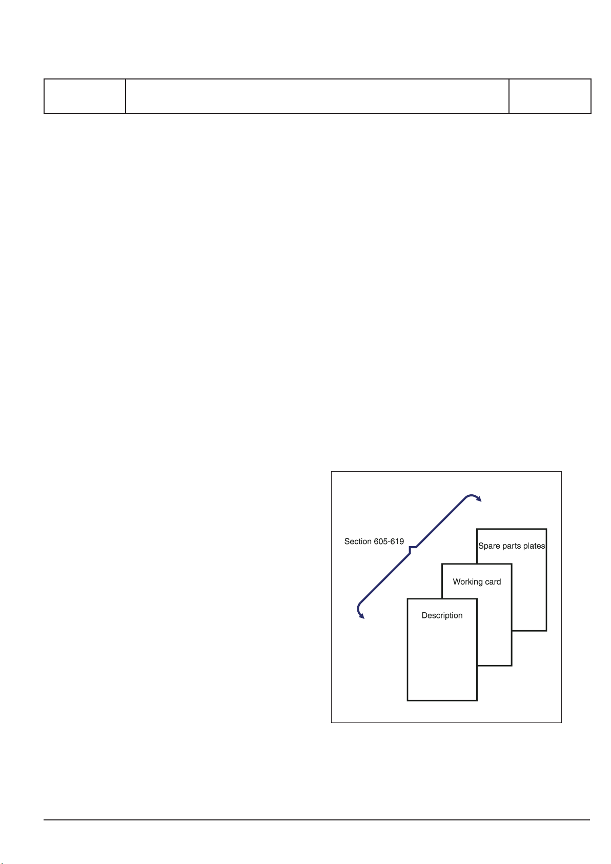
Each of these sections starts with technical descriptions of the systems/components, followed by
working cards and the spare parts illustration plates
and parts lists.
08028-0D/H5250/94.08.12
10.47 - ES0
Fig. 1. Structuring of instruction book.

MAN Diesel
Description
Page 1 (2)
General
Proper maintenance, which is the aim of this book,
constitutes the crucial point in obtaining optimum
safety in the engine room. The general measures
mentioned here should therefore be a natural routine
to the entire engine room staff.
Cleanliness
The engine room should be kept clean above and
below the fl oor plates. If grit or sand blows into the
engine room when the ship is in port, the ventilation
should be stopped and ventilating ducts, skylights,
and doors in the engine room should be closed.
In particular, welding or work which causes spread ing
of grit and chips must be avoided near the engine,
unless this is closed or covered, and the turbo charger air intake fi lters are covered.
The exterior of the engine should be kept clean and
the paintwork maintained so that leakages can easily
be detected.
Safety
600.02
Edition 06H
General
Spares
Large spare parts should, as far as possible, be placed well strapped near the area of application and
accessible by crane. The spare parts should be well
preserved against corrosion and protected against
mechanical damage. The stock should be checked
at intervals and replenished in time.
Light
Ample working light should be permanently installed
at appropriate places in the engine room, and portable working light, in explosion-proof fi ttings, should
be obtainable everywhere.
Freezing
If there is a risk of damage due to freezing when the
plant is out of service, engines, pumps, coolers, and
pipe systems should be emptied of cooling water.
Warning
Fire
If the crankcase is opened before the engine is cold,
welding and the use of naked light will involve the risk
of explosions and fi re. The same applies to inspec tion
of oil tanks and the space below the fooler. Attention
is furthermore drawn to the danger of fi re when using
paint and solvents with a low fl ash point. Porous
insulating material drenched with oil from leakages
is easily infl ammable and should be re newed. See
also: "Ignition in crankcase" in section 603.
Order
Hand tools should be placed easily accessible on
tool boards. Special tools should be fastened to tool
panels (if supplied) in the engine room close to the
area of application. No major objects must be left
unfastened, and the fl oor and passages should be
08028-0D/H5250/94.08.12
kept clear.
The opening of cocks may cause discharge of hot
liquids or gases. The dismantling of parts may cause
springs to be released.
The removal of fuel valves (or other valves in the
cylinder head) may cause oil to run down to the
piston crown, and if the piston is hot, an explosion
may then blow out the valve.
When testing fuel valves with the hand pump, do not
touch the spray holes, as the jet may pierce the skin.
Think out beforehand which way the liquids, gases
or fl ames will move, and keep clear.
Crankcase work
Check beforehand that the starting air supply to the
engine is shut off.
91.12 - ES0U

MAN Diesel
600.02
Edition 06H
General
Feeling over
Whenever repairs or alterations have been made to
the running gear, apply the "Feel-over sequence"
until ensured that there is no undue heating, oilmist formation, blow-by, or failure of cooling water
or lubricating oil systems.
Feel-over sequence
Feel-over after 5-15 and 30 minutes' idle running and
fi nally when the engine is running at full load. See
also "Starting-up sequence" in the section 602.
Safety
Description
Page 2 (2)
Turning with air
After prolonged out-of-service periods or overhaul
work which may involve a risk of accumulation of
liquid in the combustion spaces, turning with open
indicator cocks should always be effected, through
at least two complete revolutions.
Check and maintain
Lubricating oil condition, fi lter elements and measuring equipment.
91.12 - ES0U

MAN Diesel & Turbo
Description
Page 1 (1)
Cross Section
600.05
Edition 07H
L28/32H
10.36 - ES1

MAN Diesel
Description
Page 1 (1)
Key for Engine Designation
Engine Type Identifi cation
The engine types of the MAN B&W programme are identifi ed by the following fi gures:
6 L 28/32 H MCR
No of cylinders
5, 6, 7, 8, 9
12, 16, 18
600.10
Edition 02H
General
Engine Type
L : In-line
V : V-built
Cyl. diam/stroke
16/24 : 160/240
21/31 : 210/310
23/30 : 225/300
27/38 : 270/380
28/32 : 280/320
32/40 : 320/400
Design Variant
Rating
MCR : Maximum continuous rating
ECR : Economy continuous rating
08028-0D/H5250/94.08.12
04.08 - ES1
MAN Diesel
Description
Page 1 (1)
Front End
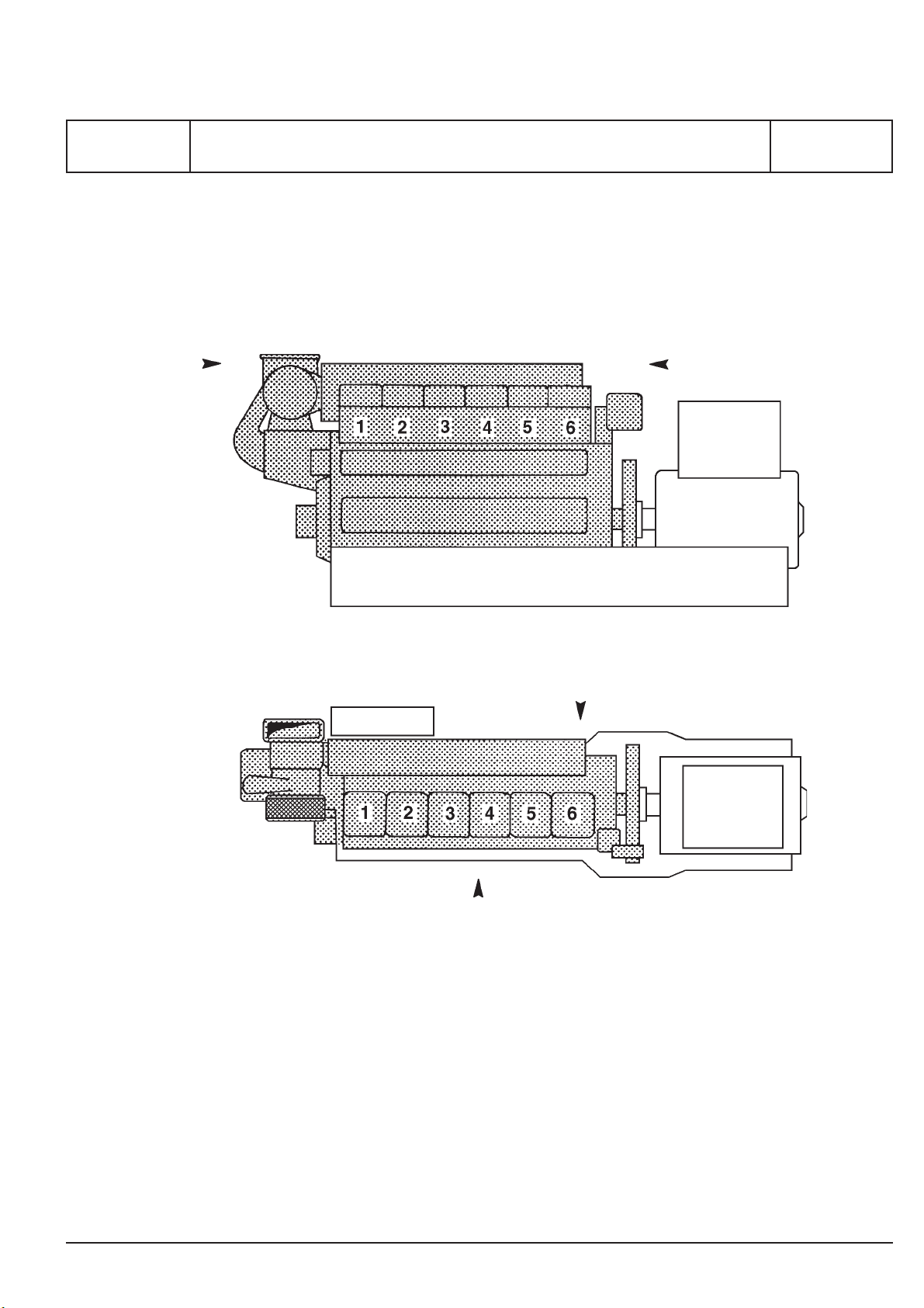
Designation of Cylinders
600.11
Edition 01H
L28/32H
Flywheel end
08028-0D/H5250/94.08.12
Exhaust Side / Right Side
Control Side / Camshaft Side / Left Side
89.17 - ES1S-L
MAN Diesel & Turbo
Description
Page 1 (1)
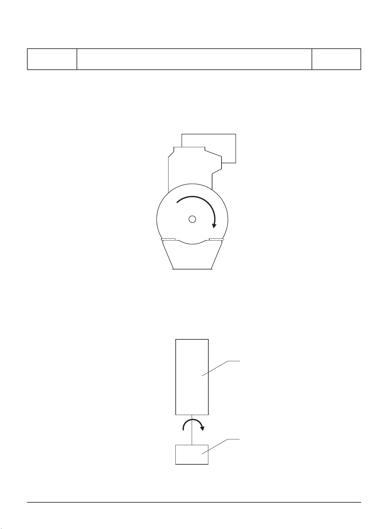
Engine Rotation Clockwise
600.12
Edition 02H
General
Direction of rotation seen from flywheel end “Clockwise”
Engine
Alternator
10.39 - ES1
MAN Diesel & Turbo
Description
Page 1 (2)
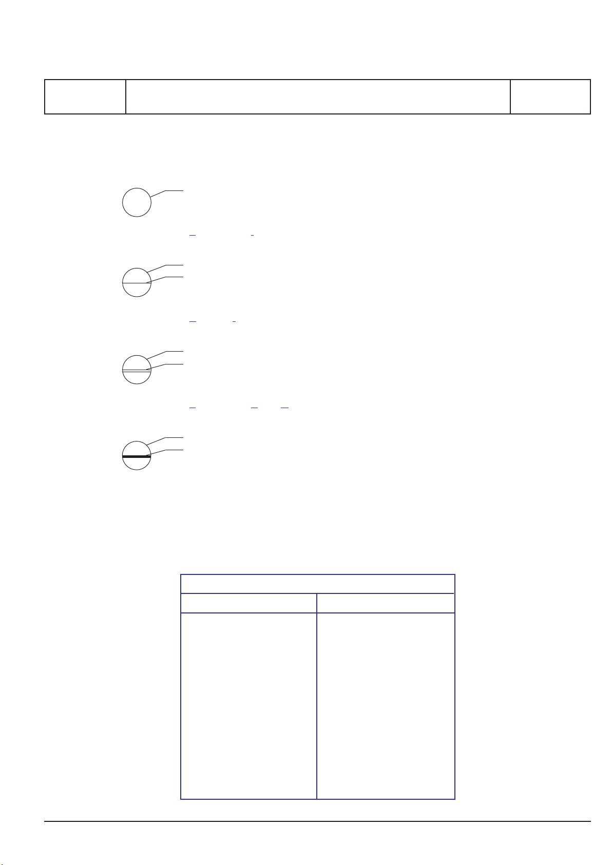
Explanation of Symbols
TI
40
PI
22
TAH
12
Code Identification for Instruments
Measuring device
Local reading
Temperature Indicator
No. 40 *
Measuring device
Sensor mounted on engine/unit
Reading/identification mounted in a panel on the engine/unit
Pressure Indicator
No. 22 *
Measuring device
Sensor mounted on engine/unit
Reading/identification outside the engine/unit
600.20
Edition 03H
General
PT
22
Temperature Alarm High
No. 12 *
Measureing device
Sensor mounted on engine/unit
Reading/identification in a panel on the engine/unit and reading/indication outside the engine/unit
Pressure Transmitting
No. 22 *
* Refer to standard location and text for instruments on the following pages.
Specification of letter code for measuring devices
1st letter Following letters
F Flow A Alarm
L Level D Differential
P Pressure E Element
S Speed, System H High
T Temperature I Indicating
11.19 - ES1
U Voltage L Low
V Viscosity S Switching, Stop
X Sound T Transmitting
Z Position X Failure
V Valve, Atuator

MAN Diesel & Turbo
600.20
Edition 03H
Code Identification for Instruments
General
Standard Text for Instruments
Diesel Engine/Alternator
LT Water System
01 inlet to air cooler 04 inlet to alternator 07 inlet to lub. oil cooler
02 outlet from air cooler 05 outlet from alternator 08 inlet to fresh water cooler (SW)
03 outlet from lub. oil cooler 06 outlet from fresh water cooler (SW) 09
HT Water System
10 inlet to engine 14 inlet to HT air cooler 17 outlet from fresh water cooler
10A FW inlet to engine 14A FW inlet to air cooler 18 inlet to fresh water cooler
11 outlet from each cylinder 14B FW outlet from air cooler 19 preheater
12 outlet from engine 15 outlet from HT system 19A inlet to prechamber
13 inlet to HT pump 16 outlet from turbocharger 19B outlet from prechamber
Lubricating Oil System
20 inlet to cooler 24 sealing oil - inlet engine 28 level in base frame
21 outlet from cooler / inlet to filter 25 prelubricating 29 main bearings
22 outlet from filter / inlet to engine 26 inlet rocker arms and roller guides
23 inlet to turbocharger 27 intermediate bearing / alternator bearing
Description
Page 2 (2)
Charging Air System
30 inlet to cooler 34 charge air conditioning 38
31 outlet from cooler 35 surplus air inlet 39
32 jet assist system 36 inlet to turbocharger
33 outlet from TC filter / inlet to TC compr. 37 charge air from mixer
Fuel Oil System
40 inlet to engine 44 outlet from sealing oil pump 48
41 outlet from engine 45 fuel-rack position 49
42 leakage 46 inlet to prechamber
43 inlet to filter 47
Nozzle Cooling System
50 inlet to fuel valves 54 58 oil splash
51 outlet from fuel valves 55 valve timing 59 alternator load
52 56 injection timing
53 57 earth/diff. protection
Exhaust Gas System
60 outlet from cylinder 64 68
61 outlet from turbocharger 65 69
62 inlet to turbocharger 66
63 compustion chamber 67
Compressed Air System
70 inlet to engine 74 inlet to reduction valve 78 inlet to sealing oil system
71 inlet to stop cylinder 75 microswitch for turning gear 79
72 inlet to balance arm unit 76 inlet to turning gear
73 control air 77 waste gate pressure
Load Speed
80 overspeed air 84 engine stop 88 index - fuel injection pump
81 overspeed 85 microswitch for overload 89 turbocharger speed
82 emergency stop 86 shutdown 90 engine speed
83 engine start 87 ready to start
Miscellaneous
91 natural gas - inlet to engine 94 cylinder lubricating 97 remote
92 oil mist detector 95 voltage 98 alternator winding
93 knocking sensor 96 switch for operating location 99 common alarm
100 inlet to MDO cooler 101 outlet to MDO Cooler 102 alternator cooling air
11.19 - ES1
MAN Diesel
Description
Page 1 (1)
Introduction to Planned Maintenance Programme
General
The overhaul intervals are based on operation on
a specifi ed fuel oil quality at normal service output,
which means 70-100% of MCR.
In the long run it is not possible to obtain a secure
and optimal economic running without an effective
main tenance system.
With the structure and amount of information in the
maintenance programme, it can be integrated in the
entire ship's/power station's maintenance system or
it can be used separately.
The crux of the maintenance system is the key diagram, see page 600.25, indicating the inspection
intervals for the components/systems, so that the
crew can make the necessary overhauls, based on
the engines' condition and/or the time criteria.
600.24
Edition 02H
General
4. Related procedures - indicates other works,
depending on this work - or works which would be
expedient to carry out.
5. Indicates x number of men in x number of hours
for accomplishing the work.
The stated consumption of hours is only intended
as guide.
Experience with the specifi c station/crew may lead
to a bringing up-to-date.
6. Refers to data, which are required for carrying
out the work.
7. Special tools, which must be used. Please note
that not all tools are standard equip ment.
8. Various requisite hand tools.
The stated, recommended intervals are only for
guidance as different service conditions, the quality
of the fuel oil and the lubricating oil, treatment of the
cooling water, etc, will decisively infl uence on the
actual service results and thus the intervals between
necessary overhauls.
Experience with the specifi c plant/crew is to be used
for adjustment of time between overhaul. Further it
is to be used for adjusting the timetable stated for
guidance in the working cards.
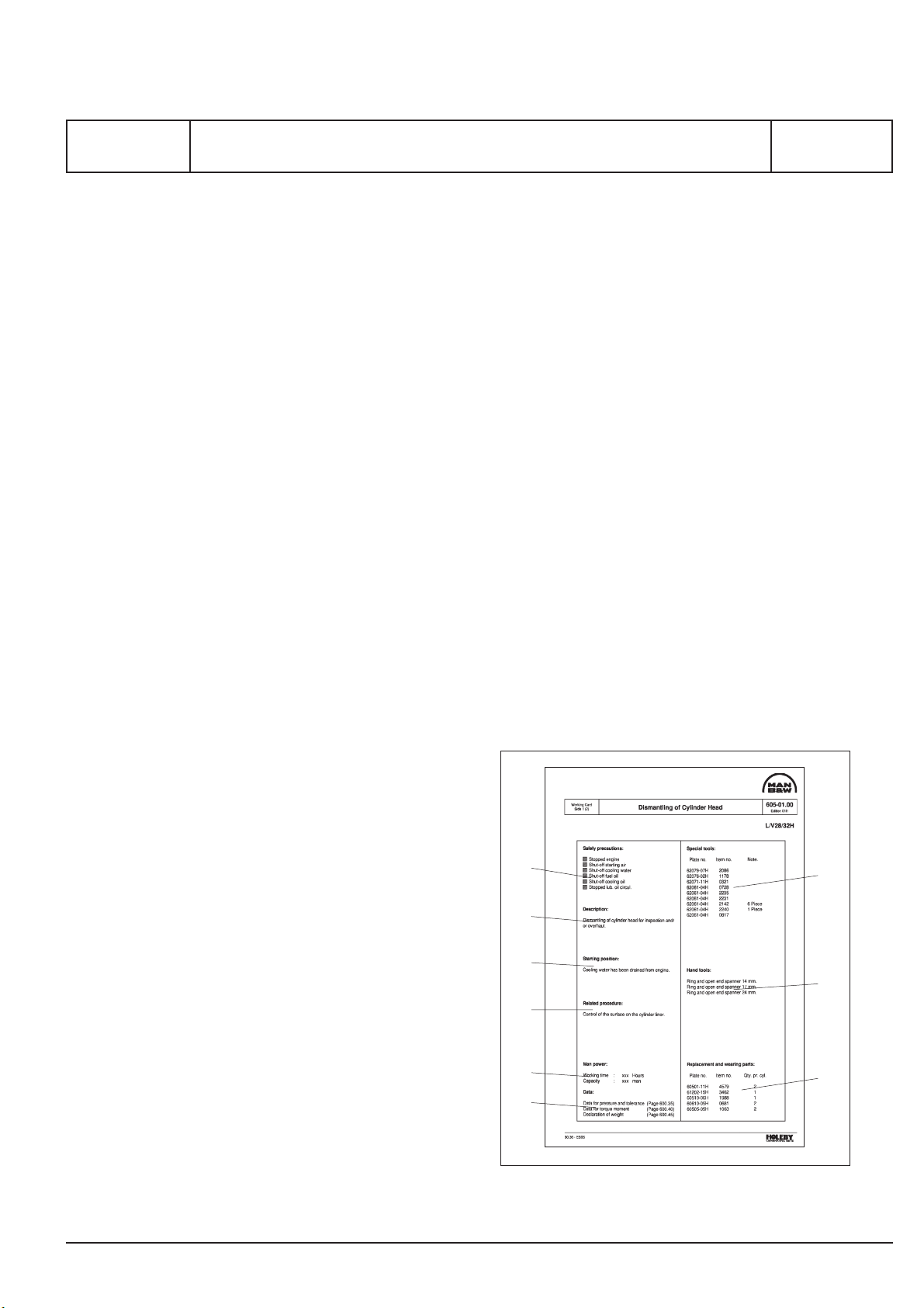
Working cards
Each of the working cards can be divided into two:
a front page and one or several pages, describing
and illustrating the maintenance work.
The front page indicates the following:
1. Safety regulations, which MUST be carried
through before the maintenance work can start.
2. A brief description of the work.
08028-0D/H5250/94.08.12
3. Reference to work, which must be carried out,
if any, before the maintenance work can start.
9. Indicates the components/parts, which it is
advisible to replace during the maintenance work.
Please note, that this is a condition for the intervals
stated.
1
2
3
4
5
6
7
8
9
94.35 - ES0S
Fig 1. Guidance instruction for working cards.

MAN Diesel
Description
Page 1 (4)
Description
Planned Maintenance Program
● = Overhaul to be carried out
■ = Check the condition
Operating of Engine:
Readings of data for Engine and Generator, with refe-
rence to "Engine Performance Data", section 602-1 .......
Cylinder Head:
Inlet and exhaust valve - Overhaul and regrinding of
spindel and valve seat .....................................................
Inspection of inlet, exhaust valves and valve guide .........
Check of valve rotators rotation during engine rotation ...
Sleeve for fuel injector .....................................................
Safety valve - Overhaul and adjustment of opening
pressure ..........................................................................
Indicator valve .................................................................
Time Between Overhaul
50
200
8000
2000
16000
32000
Check new/
Overhauled parts
after -hours
■
●
■
■
■
■
■ ■
Daily
Weekly
Montly
3th month
600.25
Edition 33H
L28/32H
Working
Card
No.
Observations
602-01.00
605-01.10
605-01.05
605-01.05
605-01.30
605-01.25
605-01.26
Cylinder head cooling water space - Inspection ..............
Cylinder head nut - Retightening ..................................... 200
Piston, Connecting Rod and Cylinder Liner:
Inspection of piston .........................................................
Piston ring and scraper ring ............................................
Piston pin and bush for connecting rod - Check of
clearance .........................................................................
Connecting rod - Measuring of big-end bore ...................
Inspection of big-end bearings shells ..............................
Connecting rod - Retightening ......................................... 200
Cylinder liner - Cleaning, honing and measuring ............
Cylinder liner removed - Check the water space and
guide ring in frame ...........................................................
Camshaft and Camshaft Drive:
08028-0D/H5250/94.08.12
Camshaft - Inspection of gear wheels, bolt, connections
etc. ................................................................................... 200
Camshaft bearing - Inspection of clearance ....................
Camshaft adjustment - Check the condition ....................
■
■
●
■
■
■
■
●
■
■
■
■
605-01.45
605-01.40
606-01.10
606-01.10
606-01.15
606-01.15
606-01.16
606-01.25
606-01.35
606-01.40
607-01.00
607-01.05
607-01.20
09.48 - ES0
Lubrication of camshaft bearing - Check .........................
■
607-01.00

MAN Diesel
600.25
Edition 33H
Planned Maintenance Program
L28/32H
Description
Operating Gear for Inlet Valves, Exhaust Valves and
Fuel Injection Pumps:
Roller guide for valve gear ...............................................
Valve gear - Valve bridge, spring, push rod, etc ..............
Roller guide for fuel injection pump .................................
Roller guide housing ........................................................
Inlet and exhaust valve - Check and adjustment of valve
clearance .........................................................................
● = Overhaul to be carried out
■ = Check the condition
Time Between Overhaul
50
200
2000
8000
16000
Check new/
Overhauled parts
after -hours
■
■
■
■
■
Daily
32000
Weekly
Montly
3th month
Description
Page 2 (4)
Working
Card
No.
Observations
608-01.00
608-01.10
608-01.05
608-01.10
608-01.10
Lubricating of operating gear - Check .............................
Control and Safety System, Automatics and
Instruments:
Safety, alarm and monitoring equipment ........................
Jet system - Adjustment ..................................................
Pick-up - Adjustment .......................................................
Governor - Check oil level, see governor instruction
book, section 609 ............................................................
Crankshaft and Main Bearing:
Checking of main bearings aligment, (autolog) ...............
Inspection af main bearing ..............................................
Inspection of guide bearing .............................................
Vibration damper - Check the condition ..........................
Lubricating of gear wheel for lub. oil pump and cooling
water pump etc. ...............................................................
Counter weight - Retightening, see page 600.40 ............ 200
■
■
■
■
■
■
■
■
■
■
■
608-01.00
608-01.05
609-01.00
609-01.00
609-10.00
610-01.00
610-01.05
610-01.10
610-04.00
Main- and guide bearing cap - Retightening ................... 200
■
610-01.05
610-01.10
09.48 - ES0
08028-0D/H5250/94.08.12

MAN Diesel
Description
Page 3 (4)
Description
Planned Maintenance Program
● = Overhaul to be carried out
■ = Check the condition
Engine Frame and Bedplate:
Holding down bolts - Retightening, see page 600.40 ...... 200
Bolts between engine frame and base frame -
Retightening, see page 600.40 ....................................... 200
For flexible mounted engines - Check anti-vibration
mountings ........................................................................ 200
Safety cover - Function test .............................................
Time Between Overhaul
50
200
2000
8000
16000
Check new/
Overhauled parts
after -hours
■
■
■
■
Daily
32000
Weekly
Montly
3th month
600.25
Edition 33H
L28/32H
Working
Card
No.
Observations
619-03.00
611-01.00
Turbocharger System:
Dry cleaning of turbine side .............................................
Wet cleaning of turbine side ............................................
Water washing of compressor side .................................
Cleaning of air filter - Compressor side (see turbo-
charger instruction book) .................................................
Turbocharger complete - Dismantling, cleaning, inspec-
tion etc. (see turbocharger instruction book) ...................
Charging air cooler - Cleaning and inspection ................
Charging air cooler housing - Draining ............................
Exhaust pipe - Compensator ...........................................
Compressed Air System:
Air starter motor - Dismantling and inspection ................
Function test - Main starting valve, starting valve, main
valves and emergency start valve ...................................
Dirt separator - Dismantling and cleaning .......................
Muffler - Dismantling and cleaning ..................................
●
●
●
■
●
■
■
■
●
●
612-10.00
612-15.00
612-05.00
612-01.00
613-01.30
613-01.40
Compressed air system - Draining ..................................
Compressed air system - Check of the system ...............
08028-0D/H5250/94.08.12
Drain of bowl ....................................................................
(filter element to be replaced when pressure drop
exceeds 0.7 bar)
09.48 - ES0
●
■
●
613-01.90
613-01.90
613-01.21

MAN Diesel
600.25
Edition 33H
Planned Maintenance Program
L28/32H
Description
Fuel Oil System and Injection Equipment:
Fuel oil filter - Dismantling and cleaning ..........................
Fuel oil feed pump ...........................................................
Fuel oil injection pump - Dismantling and cleaning .........
Fuel injection valve - Adjustment of opening pressure .... 200
Fuel oil high-pressure pipe - Dismantling and check .......
Adjustment of the maximum combustion pressure ..........
Fuel oil system - Check the system .................................
Nozzle cooling system - Check the system .....................
● = Overhaul to be carried out
■ = Check the condition
Time Between Overhaul
50
200
2000
8000
32000
16000
Check new/
Overhauled parts
after -hours
●
●
●
■
■
●
■
■
Daily
Weekly
Montly
3th month
Description
Page 4 (4)
Working
Card
No.
Observations
614-01.15
614-10.00
614-01.05
614-01.10
614-01.05
614-05.01
614-01.90
614-01.90
Fuel oil - Oil samples after every bunkering, see sec.604
Lubricating Oil System:
Lubricating oil pump - Engine driven ...............................
Lubricating oil filter - Cleaning and exhange ...................
Lubricating oil cooler .......................................................
Prelubricating pump - El. driven ......................................
Thermostatic valve ..........................................................
Centrifugal filter - Cleaning and exhange of paper ..........
Lubricating oil - Oil samples, see section 604 .................
Lubricating oil system - Check the system ......................
Cooling Water System:
Cooling water pump - Engine driven (sea water and
fresh water)......................................................................
Thermostatic valve ..........................................................
Cooling water system - Check the system ......................
Cooling water system - Water samples, see sec. 604 .....
■
●
●
■
■
●
■
■
■
■
■
■ ■
615-01.00
615-01.10
615-06.00
615-01.05
615-01.20
615-15.00
615-01.90
616-01.90
09.48 - ES0
08028-0D/H5250/94.08.12

MAN Diesel & Turbo
Description
Page 1 (2)
Lubricating Oil System
Temp. before cooler SAE 30
(outlet engine) SAE 40
Temp. after cooler SAE 30
(inlet engine) SAE 40
Pressure after filter (inlet eng)
Elevated pressure i.g. when
centrifugal filter installed
Pressure drop across filter
Prelubricating pressure
Pressure inlet turbocharger
Lub. oil, level in base frame
Temp. main bearings
Fuel Oil System
Pressure after filter MDO
HFO
Leaking oil
Press. nozz. cool. oil, inlet eng.
Temp. nozz. cool. oil, outlet eng.
Cooling Water System
Press. LT-system, inlet engine
Press. HT-system, inlet engine
Temp. HT-system, inlet engine
Temp. HT-system, outl. cyl.units
Temp. HT-system, outlet engine
Temp. raise across cyl. units
Exhaust Gas and Charge Air
Exh. gas temp. before TC
Exh. gas temp. outlet cyl.
Diff. between individual cyl.
Exh. gas temp. after TC
Ch. air press. after cooler
Ch. air temp. after cooler
Compressed Air System
Press. inlet engine
Operation Data & Set Points
Acceptable
value at shop
test or after
repair
<75° C
<82° C
<65° C
<72° C
>4.0 bar
>4.5 bar
<0.5 bar
>1.5 bar
<85° C
>1.3 bar
>1.8-<6 bar
<85° C
average
±25° C
<55° C
>7.5-<9 bar
PDAH 21-22
Normal Value at Full load
at ISO conditions
TI 20
TI 20
TI 22
TI 22
PI 22
PI 22
PDAH 21-22
PI 23
TE 29
PI 40
PI 40
PI 50
TI 51
PI 01
PI 10
TI 10
TI 11
TI 62
TI 60
TI 61
PI 31
TI 31
PI 70
60-75° C
65-82° C
45-65° C
50-72° C
3.5-4 bar
4-5 bar
0.5-1 bar
1.5 ±0.2 bar
75-85° C
2.5-5 bar
5-16 bar (A)
2-3 bar
80-90° C
1-2.5 bar (D)
1.5-4.6 bar
60-75° C
70-85° C
max. 10° C
425-475° C
270-380° C
275-350° C
2-2.5 bar
35-55° C
7-9 bar
Alarm Set point Autostop of engine
TAH 20
TAH 20
TAH 22
TAH 22
PAL 22
PAL 22
LAL 25
LAL 28/
LAH 28
TAH 29
PAL 40
PAL 40
LAH 42
PAL 50
PAL 01
PAL 10
TAH 12
TAH 12-2
TAH 62
TAH 62-2
TAH 60
TAD 60
TAH 61
TAH 31
PAL 70
90° C
100° C
75° C
85° C
3 bar
3.5 bar
1.5 bar
level switch
low/high level
95° C
1.5 bar
4 bar
leakage
1.5 bar (B)
95° C (B)
0.4 bar + (C)
0.4 bar + (C)
90° C
93° C
550° C
600° C
410° C
average (F)
±50° C
500° C
65° C
7 bar
TSH 22
TSH 22
PSL 22
PSL 22
TSH 12
600.30
Edition 50H
L28/32H
85° C
95° C
2.5 bar
3.0 bar
95° C
Specific plants will not comprise alarm equipment and autostop for all parameters listed above. For specific plants additional parameters
can be included. For remarks to some parameters, see overleaf.
10° C change in ambient temperature correspond to approx. 15° C exhaust gas temperature change
11.33 - ES1

MAN Diesel & Turbo
600.30
Edition 50H
L28/32H
Normal Value at Full load
Speed Control System
Engine speed
GenSets for 60 Hz
Mechanical
Elec.
GenSets for 50 Hz
Mechanical
Elec.
Turbocharger speed
Remarks to individual Parameters
A. Fuel Oil Pressure, HFO-operation.
SI 90
SI 90
SI 89
Operation Data & Set Points
Acceptable
at ISO conditions
720 rpm
750 rpm
(G)
value at shop
test or after
repair
820 rpm
855 rpm
E. Limits for Turbocharger Overspeed Alarm
(SAH 89)
Alarm Set point Autostop of engine
SAH 81
SAH 81
SAH 89
815 rpm
850 rpm
(E)
SSH 81
SSH 81
SSH 81
SSH 81
Descriptoin
Page 2 (2)
825 rpm
815 rpm
860 rpm
850 rpm
When operating on HFO, the system pressure must
be sufficient to depress any tendency to gasification
of the hot fuel.
The system pressure has to be adjusted according
to the fuel oil preheating temperature.
B. Nozzle Cooling Oil System
The nozzle cooling oil system is only applied for Tier
II marine and stationary engines.
C. Cooling Water Pressure, Alarm Set Points.
As the system pressure in case of pump failure will
depend on the height of the expansion tank above
the engine, the alarm set point has to be adjusted
to 0.4 bar plus the static pressure.
D. Press. LT -system, inlet engine (PI 01)
With two-string cooling water system the normal
value can be higher, max. 4.0 bar.
Engine type 720 rpm 750 rpm
5L28/32H 42,680 42,680
6L28/32H 42,680 42,680
7L28/32H 34,900 34,900
8L28/32H 34,900 34,900
9L28/32H 36,180 36,180
F. Exhaust Gas Temperatures
The exhaust gas temperature deviation alarm is
normally ±50° C with a delay of 1 min., but at start-up
the delay is 5 min. Furthermore the deviation limit is
±100° C if the average temperature is below 200° C.
G. Turbocharger Speed
Normal value at full load of the turbocharger is dependent on engine type (cyl. no) and engine rpm.
The value given is just a guide line. Actual values
can be found in the acceptance test protocol.
11.33 - ES1
 Loading...