

Mandam Hybro 3, Hybro 6, 0 H, Hybro 4, Hybro 8 Instruction Manual
P.P.H. MANDAM Sp. z o.o.
ul. Toruńska 2 44-100 Gliwice, Poland
e-mail: mandam@mandam.com.pl
Tel.: 032 232 26 60 Fax: 032 232 58 85
NIP (VAT no.): 648 000 16 74
REGON (Registration no.): P – 008173131
INSTRUCTION MANUAL
HYBRO weeder

1
CE DECLARATION OF CONFORMITY
FOR A MACHINE
Pursuant to the Ordinance of the Ministry of Economy of 21 October 2008 (Journal of Laws No. 199,
item 1228) and the Directive of the European Union no. 2006/42/EC of 17 May 2006
Przedsiębiorstwo Produkcyjno-Handlowe „MANDAM” Sp. z o.o.
ul. Toruńska 2
44-100 Gliwice, Poland
hereby declares at its sole responsibility that the following machine:
under this declaration, complies with:
the Ordinance of the Ministry of Economy of 21 October 2008 on fundamental
requirements for machinery (Journal of Laws No. 199, item 1228)
and the Directive of the European Union 2006/42/EC of 17 May 2006.
The persons responsible for the technical documentation for the machine:
Jarosław Kudlek, Łukasz Jakus,
ul. Toruńska 2, 44-100 Gliwice, Poland
For assessment of compliance the following standards have been applied:
PN-EN ISO 13857:2010,
PN-EN ISO 4254-1:2009,
PN-EN ISO 12100-1:2005/A1:2009,
PN-EN ISO 12100-2:2005/A1:2009
PN-EN 982+A1:2008
This EC Declaration of Conformity shall be cancelled
if the machine is modified or redesigned without consent of the manufacturer.
Gliwice, 18 April 2014 ………………………………………
Place and date of issue Surname, first name, position
and signature of the
authorised person
HYBRO WEEDER
type/model: ……………………………..
year of manufacture: ……………………
serial number: …………………………..

2
Table of Contents
1. SAFETY SIGNS AND INSCRIPTIONS ............................................................ 3
1.1. SAFETY SIGNS AND INSCRIPTIONS ..................................................... 4
1.2. Hybro weeder design ................................................................... 6
2. Intended use of the Hybro weeder .......................................................... 7
3. General safety information ................................................................... 8
3.1. Attaching the tractor ................................................................... 8
3.2. Hydraulic system ........................................................................ 9
3.3. Transport on public roads .............................................................. 9
3.4. Description of residual risk ........................................................... 10
3.5. Residual risk assessment .............................................................. 10
4. General operation instructions ............................................................. 10
4.1. Before using the Hybro weeder ...................................................... 11
4.2. Adjustments ............................................................................. 12
4.3. Protection of the hydraulic system .................................................. 13
4.4. Operating the Hybro weeder ......................................................... 14
4.5. Maintenance............................................................................. 14
4.6. Replacement procedures .............................................................. 16
5. Storage ......................................................................................... 16
6. Transport ....................................................................................... 16
7. Disassembly and withdrawal from service ................................................ 17
8. Technical data of the Hybro weeder ....................................................... 18
9. General warranty terms ..................................................................... 19
Warranty card .................................................................................... 20

3
1. Introduction
Congratulations on your purchase of the HYBRO weeder.
This instruction manual contains the information on hazards that may occur during work
with the device, technical data and the most important guidelines and
recommendations to be known and applied to ensure a proper operation. Keep this
manual for future reference. Should you have any problems with understanding any
statement in the instruction manual, please contact the manufacturer.
The following mark indicates the guidelines that are important due to safety reasons:
The machine is provided with a name plate to be found on the main frame. The name
plate presents basic data allowing the identification of the machine:
Type Number
Weight Year of manufacture
The warranty for the HYBRO weeder is valid for 24 months and runs from the date of
sale.
The warranty card can be found at the end of the manual.
The warranty card constitutes an integral part of the machine.
Whenever you request any information on spare parts, provide the serial number.
For more information on spare parts:
• please visit our website at: http://mandam.com.pl/parts/
• or call us at +48 668 662 239
• e-mail: czesci@mandam.com.pl
Machine identification
Identification data of the HYBRO weeder, including basic information on the
manufacturer and the machine and CE marking, can be found on the rating plates placed
on the load-bearing frame.
4
1.1 SAFETY SIGNS AND INSCRIPTIONS
The following signs and inscriptions can be found on the machine. Protect the signs and
safety inscriptions so that they cannot be lost or become illegible.
If lost or illegible, replace the signs and inscriptions with new ones.
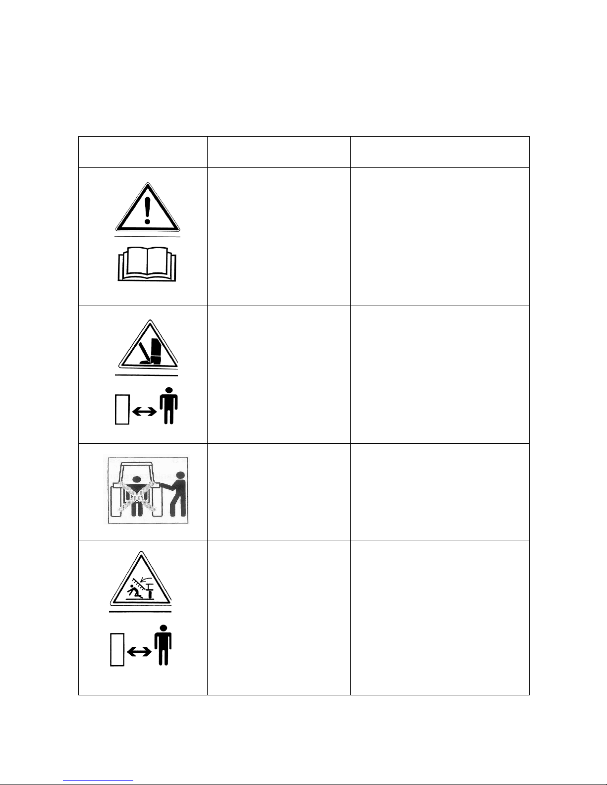
Table 1. Information and warning signs
Safety sign
Meaning of the safety sign
Location on the machine
Read the instruction
manual prior to
operating the
machine.
Weeder frame adjacent to
the mounting of the upper
fastener
Danger of toe or foot crush
Weeder frame adjacent to
the mounting of the upper
fastener
Keep clear from lift bars
while controlling the lift
Weeder frame adjacent to
the mounting of the upper
fastener
Keep clear from foldable
and moving parts of the
machine
Front part of the mid frame
adjacent to side frames
5
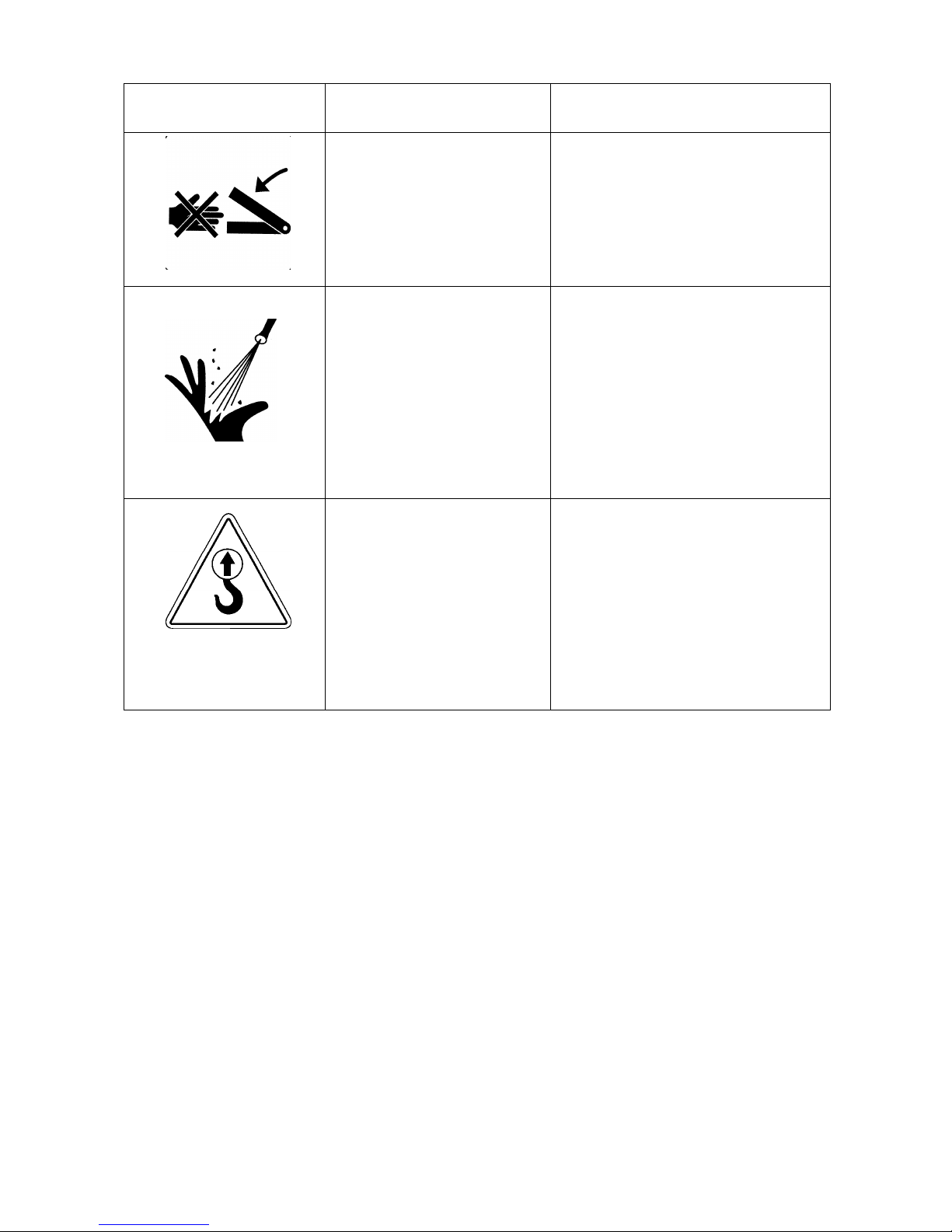
Safety sign
Meaning of the safety sign
Location on the machine
Do not reach into the
crushing zone if the
elements can move
Mid frame adjacent to side frames
Liquid jet under pressure –
injury
Cylinders
Fixing point for
transport belts
Upper part of the drawbar (upper
fastener bolt)
Rear part of the frame:
• rigid frame (adjacent to
the roller depth
adjustment)
• foldable frame (adjacent
to the upper fastener
bolt on the mid frame)
6
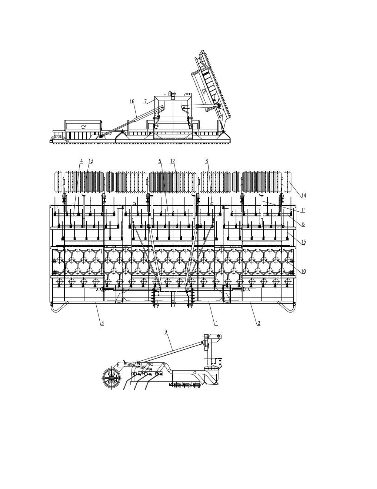
1.2. Hybro weeder design
Fig. 1 Design of the HYBRO weeder: 1 - central frame, 2 - right side frame, 3 - left side
frame, 4 - right side tool section, 5 - central tool section, 6 - left side tool section, 7 drawbar, 8 - foot, 9 - strip, 10 - weeder grid, 11 - section adjustment mechanism, 12 central cast iron shaft Ø525, 13 - right side cast iron shaft Ø525, 14 - left side cast iron
shaft Ø525, 15 - spring tine, 16 - hydraulics
 Loading...