

Page 1

MAN B&W S 65ME-C8. 2-GI
199 02 43 -1.0
This Project Guide is intended to provide the information necessary for the layout of a marine propulsion
plant.
The information is to be considered as preliminary. It is intended for the project stage only and subject to
modification in the interest of technical progress. The Project Guide provides the general technical data
available at the date of issue.
It should be noted that all figures, values, measurements or information about performance stated in this
project guide are for guidance only and should not be used for detailed design purposes or as a substitute for specific drawings and instructions prepared for such purposes.
Data updates
Data not finally calculated at the time of issue is marked ‘Available on request’. Such data may be made
available at a later date, however, for a specific project the data can be requested. Pages and table entries
marked ‘Not applicable’ represent an option, function or selection which is not valid.
The latest, most current version of the individual Project Guide sections are available on the Internet at:
www.marine.man.eu → ’Two-Stroke’.
Extent of Delivery
The final and binding design and outlines are to be supplied by our licensee, the engine maker, see Chapter 20 of this Project Guide.
In order to facilitate negotiations between the yard, the engine maker and the customer, a set of ‘Extent of
Delivery’ forms is available in which the basic and the optional executions are specified.
Electronic versions
This Project Guide book and the ‘Extent of Delivery’ forms are available on the Internet at:
www.marine.man.eu → ’Two-Stroke’, where they can be downloaded.
Edition 0.5
May 2014
MAN B&W S65ME-C8.2-GI-TII
Project Guide
Electronically Controlled
Dual Fuel Two-stroke Engines
Page 2

MAN B&W S 65ME-C8. 2-GI
199 02 43 -1.0
MAN Diesel & Turbo
Teglholmsgade 41
DK2450 Copenhagen SV
Denmark
Telephone +45 33 85 11 00
Telefax +45 33 85 10 30
[email protected]
www.mandieselturbo.com
Copyright 2014 © MAN Diesel & Turbo, branch of MAN Diesel & Turbo SE, Germany, registered with the Danish
Commerce and Companies Agency under CVR Nr.: 31611792, (herein referred to as “MAN Diesel & Turbo”).
This document is the product and property of MAN Diesel & Turbo and is protected by applicable copyright laws.
Subject to modification in the interest of technical progress. Reproduction permitted provided source is given.
7020-0207-00ppr May 2014
All data provided in this document is non-binding. This data serves informational purposes only and is especially not guaranteed in any way.
&GRGPFKPIQPVJGUWDUGSWGPVURGEKǣEKPFKXKFWCNRTQLGEVUVJGTGNGXCPVFCVCOC[DGUWDLGEVVQEJCPIGUCPFYKNN
DGCUUGUUGFCPFFGVGTOKPGFKPFKXKFWCNN[HQTGCEJRTQLGEV6JKUYKNNFGRGPFQPVJGRCTVKEWNCTEJCTCEVGTKUVKEUQH
GCEJKPFKXKFWCNRTQLGEVGURGEKCNN[URGEKǣEUKVGCPFQRGTCVKQPCNEQPFKVKQPU
+HVJKUFQEWOGPVKUFGNKXGTGFKPCPQVJGTNCPIWCIGVJCP'PINKUJCPFFQWDVUCTKUGEQPEGTPKPIVJGVTCPUNCVKQPVJG
English text shall prevail.
Page 3

MAN B&W
MAN Diesel
Engine Design ....................................................................... 1
Engine Layout and Load Diagrams, SFOC .............................. 2
Turbocharger Selection & Exhaust Gas By-pass .................... 3
Electricity Production ............................................................ 4
Installation Aspects ............................................................... 5
List of Capacities: Pumps, Coolers & Exhaust Gas ................. 6
Fuel ...................................................................................... 7
Lubricating Oil ...................................................................... 8
Cylinder Lubrication .............................................................. 9
Piston Rod Stuffing Box Drain Oil .......................................... 10
Central Cooling Water System ............................................... 11
Seawater Cooling System ..................................................... 12
Starting and Control Air ......................................................... 13
Scavenge Air ......................................................................... 14
Exhaust Gas .......................................................................... 15
Engine Control System .......................................................... 16
Vibration Aspects .................................................................. 17
Monitoring Systems and Instrumentation .............................. 18
Dispatch Pattern, Testing, Spares and Tools ........................... 19
Project Support and Documentation ...................................... 20
Appendix .............................................................................. A
Contents
Page 4

Page 5

MAN B&W Contents
Chapter Section
MAN Diesel
MAN B&W S 65ME-C8. 2-GI
1 Engine Design
The ME-GI dual fuel engine 1.00 1989151-6.1
The fuel optimised ME Tier II engine 1.01 1988537-1.4
Tier II fuel optimisation 1.01 1989158-9.0
Engine type designation 1.02 1983824-3.9
Power, speed, SFOC 1.03 1988987-5.1
Engine power range and fuel oil consumption 1.04 1984917-2.4
Performance curves 1.05 1985331-6.2
ME-GI Engine description 1.06 1988914-5.2
2 Engine Layout and Load Diagrams, SFOC
Engine layout and load diagrams 2.01 1983833-8.5
Propeller diameter and pitch, influence on optimum propeller speed 2.02 1983878-2.6
Layout diagram sizes 2.03 1988277-0.7
Engine layout and load diagrams 2.04 1986993-5.3
Diagram for actual project 2.05 1988329-8.1
Specific fuel oil consumption, ME versus MC engines 2.06 1988655-6.0
SFOC for high efficiency turbochargers 2.07 1988692-6.0
SFOC reference conditions and guarantee 2.08 1988341-6.1
Examples of graphic calculation of SFOC 2.08 1988634-1.0
SFOC calculations, example 2.10 1988418-5.0
Fuel consumption at an arbitrary load 2.11 1983843-4.5
3 Turbocharger Selection & Exhaust Gas Bypass
Turbocharger selection 3.01 1988728-8.0
Exhaust gas bypass 3.02 1984593-4.6
Emission control 3.03 1988447-2.2
4 Electricity Production
Electricity production 4.01 1984155-0.5
Designation of PTO 4.01 1985385-5.5
PTO/RCF 4.01 1984300-0.3
Space requirements for side mounted PTO/RCF 4.02 1984915-9.2
Engine preparations for PTO 4.03 1984315-6.3
PTO/BW GCR 4.04 1984316-8.8
Waste Heat Recovery Systems (WHRS) 4.05 1985797-7.5
WHRS generator output 4.05 1988922-8.0
WHR element and safety valve 4.05 1988288-9.1
L16/24-TII GenSet data 4.06 1988280-4.0
L21/31TII GenSet data 4.07 1988281-6.0
L23/30H-TII GenSet data 4.08 1988282-8.0
L27/38-TII GenSet data 4.09 1988284-1.0
L28/32H-TII GenSet data 4.10 1988285-3.0
Page 6

MAN B&W Contents
Chapter Section
MAN Diesel
MAN B&W S 65ME-C8. 2-GI
5 Installation Aspects
Space requirements and overhaul heights 5.01 1984375-4.7
Crane beam for overhaul of turbochargers 5.03 1990018-0.0
Crane beam for turbochargers 5.03 1984848-8.3
Engine room crane 5.04 1984893-0.1
Overhaul with Double-Jib crane 5.04 1984534-8.4
Double-Jib crane 5.04 1984541-9.2
Engine outline, galleries and pipe connections 5.05 1984715-8.3
Engine and gallery outline 5.06 1990138-9.0
Counterflanges 5.10 1989123-0.0
Counterflanges, Connection D 5.10 1986670-0.6
Counterflanges, Connection E 5.10 1987027-3.4
Engine seating and holding down bolts 5.11 1984176-5.11
Epoxy chocks arrangement 5.12 1988799-4.0
Engine seating profile 5.12 1984894-2.3
Engine top bracing 5.13 1984672-5.8
Mechanical top bracing 5.14 1984815-3.1
Components for Engine Control System 5.16 1988538-3.2
Shaftline earthing device 5.17 1984929-2.4
MAN Alpha Controllable Pitch (CP) propeller 5.18 1984695-3.6
Hydraulic Power Unit for MAN Alpha CP propeller 5.18 1985320-8.3
MAN Alphatronic 2000 Propulsion Control System 5.18 1985322-1.5
6 List of Capacities: Pumps, Coolers & Exhaust Gas
Calculation of capacities 6.01 1988291-2.0
List of capacities and cooling water systems 6.02 1987463-3.0
List of capacities, S65ME-C8.2GI 6.03 1988721-5.1
Auxiliary system capacities for derated engines 6.04 1987149-5.6
Example 1, Pumps and Cooler Capacity 6.04 1988815-1.1
Freshwater Generator 6.04 1987145-8.1
Jacket cooling water temperature control 6.04 1988581-2.0
Example 2, Fresh Water Production 6.04 1988830-5.1
Calculation of exhaust gas amount and temperature 6.04 1984318-1.3
Diagram for change of exhaust gas amount 6.04 1984420-9.6
Exhaust gas correction formula 6.04 1987140-9.0
Example 3, Expected Exhaust Gas 6.04 1988845-0.1
Page 7

MAN B&W Contents
Chapter Section
MAN Diesel
MAN B&W S 65ME-C8. 2-GI
7 Fuel
ME-GI fuel gas system 7.00 1988881-9.2
Guiding fuel gas specification 7.00 1988755-1.1
Sealing oil system 7.00 1988756-3.2
Pressurised fuel oil system 7.01 1984228-2.7
Fuel oil system 7.01 1987660-9.3
Fuel oils 7.02 1983880-4.7
Fuel oil pipes and drain pipes 7.03 1989115-8.0
Fuel oil pipe insulation 7.04 1984051-8.3
Fuel oil pipe heat tracing 7.04 1986768-4.2
Components for fuel oil system 7.05 1983951-2.8
Components for fuel oil system, venting box 7.05 1984735-0.3
Water in fuel emulsification 7.06 1988654-4.0
Gas supply system 7.07 1988637-7.2
Fuel Gas Supply systems 7.08 1988638-9.1
ME-GI gas supply auxiliary system 7.09 1988639-0.2
8 Lubricating Oil
Lubricating and cooling oil system 8.01 1984230-4.5
Hydraulic Power Supply unit 8.02 1984231-6.3
Hydraulic Power Supply unit and lubricating oil pipes 8.02 1988349-0.1
Lubricating oil pipes for turbochargers 8.03 1984232-8.5
Lubricating oil consumption, centrifuges and list of lubricating oils 8.04 1983886-5.10
Components for lube oil system 8.05 1984239-0.5
Flushing of lubricating oil components and piping system 8.05 1988026-6.0
Lubricating oil outlet 8.05 1987034-4.1
Lubricating oil tank 8.06 1984903-9.1
Crankcase venting and bedplate drain pipes 8.07 1984261-5.6
Engine and tank venting to the outside air 8.07 1989181-5.0
Hydraulic oil back-flushing 8.08 1984829-7.3
Separate system for hydraulic control unit 8.09 1984852-3.5
9 Cylinder Lubrication
Cylinder lubricating oil system 9.01 1988559-8.2
List of cylinder oils 9.01 1988566-9.1
MAN B&W Alpha cylinder lubrication system 9.02 1983889-0.10
Alpha Adaptive Cylinder Oil Control (Alpha ACC) 9.02 1987614-4.1
Cylinder oil pipe heating 9.02 1987612-0.1
Cylinder lubricating oil pipes 9.02 1985520-9.5
Small heating box with filter, suggestion for 9.02 1987937-9.1
10 Piston Rod Stuffing Box Drain Oil
Stuffing box drain oil system 10.01 1988345-3.0
11 Central Cooling Water System
Central cooling 11.01 1984696-5.5
Central cooling water system 11.02 1984057-9.5
Components for central cooling water system 11.03 1983987-2.6
Page 8

MAN B&W Contents
Chapter Section
MAN Diesel
MAN B&W S 65ME-C8. 2-GI
12 Seawater Cooling
Seawater systems 12.01 1983892-4.4
Seawater cooling system 12.02 1983893-6.5
Cooling water pipes 12.03 1988305-8.1
Components for seawater cooling system 12.04 1983981-1.3
Jacket cooling water system 12.05 1989226-1.0
Jacket cooling water pipes 12.06 1983984-7.7
Components for jacket cooling water system 12.07 1984056-7.3
Deaerating tank 12.07 1984063-8.3
Temperature at start of engine 12.08 1988346-5.0
Heating of LNG 12.09 1988946-8.1
13 Starting and Control Air
Starting and control air systems 13.01 1988970-6.2
Components for starting air system 13.02 1988973-1.0
Starting and control air pipes 13.03 1984000-4.7
14 Scavenge Air
Scavenge air system 14.01 1984004-1.5
Auxiliary blowers 14.02 1988547-8.0
Control of the auxiliary blowers 14.02 1988556-2.0
Scavenge air pipes 14.03 1984013-6.5
Electric motor for auxiliary blower 14.04 1984913-5.3
Scavenge air cooler cleaning system 14.05 1987684-9.1
Air cooler cleaning unit 14.05 1984902-7.3
Scavenge air box drain system 14.06 1984032-7.5
Fire extinguishing system for scavenge air space 14.07 1984819-0.6
Fire extinguishing pipes in scavenge air space 14.07 1988314-2.2
15 Exhaust Gas
Exhaust gas system 15.01 1984047-2.7
Exhaust gas pipes 15.02 1984070-9.4
Cleaning systems, water 15.02 1984071-0.8
Soft blast cleaning systems 15.02 1984073-4.8
Exhaust gas system for main engine 15.03 1984074-6.3
Components of the exhaust gas system 15.04 1984075-8.7
Calculation of exhaust gas back-pressure 15.05 1984094-9.3
Forces and moments at turbocharger 15.06 1984911-1.4
Diameter of exhaust gas pipe 15.07 1984914-7.3
16 Engine Control System
Engine Control System – Dual Fuel 16.00 1988930-0.2
Engine Control System ME Engine 16.01 1984847-6.9
Control System layout Mechanical- 16.01 1987923-5.2
hydraulic system with HPS 16.01 1987924-7.2
Engine Control System interface to surrounding systems 16.01 1988531-0.2
Pneumatic manoeuvring diagram 16.01 1987926-0.1
Engine Control System –GI Extension 16.02 1988931-2.1
GI Extension Interface to External Systems 16.02 1988658-1.2
Page 9

MAN B&W Contents
Chapter Section
MAN Diesel
MAN B&W S 65ME-C8. 2-GI
17 Vibration Aspects
Vibration aspects 17.01 1984140-5.3
2nd order moments on 4, 5 and 6-cylinder engines 17.02 1984220-8.8
1st order moments on 4-cylinder engines 17.02 1983925-0.5
Electrically driven moment compensator 17.03 1984222-1.6
Power Related Unbalance (PRU) 17.04 1990207-3.0
Guide force moments 17.05 1984223-3.5
Guide force moments, data 17.05 1984517-1.1
Vibration limits valid for single order harmonics 17.05 1988264-9.0
Axial vibrations 17.06 1984224-5.4
Critical running 17.06 1984226-9.3
External forces and moments in layout point 17.07 1990208-5.0
18 Monitoring Systems and Instrumentation
Monitoring systems and instrumentation 18.01 1988529-9.2
PMI Auto-tuning system 18.02 1988530-9.2
CoCoS-EDS systems 18.03 1984582-6.8
Alarm - slow down and shut down system 18.04 1987040-3.4
Class and MAN Diesel & Turbo requirements 18.04 1984583-8.10
Local instruments 18.05 1984586-3.9
Other alarm functions 18.06 1984587-5.13
Bearing monitoring systems 18.06 1986726-5.5
LDCL cooling water monitoring system 18.06 1990197-5.0
Control devices 18.06 1986728-9.4
Identification of instruments 18.07 1984585-1.6
ME-GI safety aspects 18.08 1985060-7.3
19 Dispatch Pattern, Testing, Spares and Tools
Dispatch pattern, testing, spares and tools 19.01 1987620-3.2
Specification for painting of main engine 19.02 1984516-9.6
Shop test 19.05 1988737-2.0
List of spare parts, unrestricted service 19.06 1988327-4.6
Additional spares 19.07 1988326-2.5
Wearing parts 19.08 1988369-3.2
Large spare parts, dimensions and masses 19.09 1988601-7.1
Rotor for turbocharger 19.09 1990189-2.0
List of standard tools for maintenance 19.10 1988918-2.1
20 Project Support and Documentation
Project support and documentation 20.01 1984588-7.5
Installation data application 20.02 1984590-9.3
Extent of Delivery 20.03 1984591-0.6
Installation documentation 20.04 1984592-2.5
ME-GI installation documentation 20.05 1988683-1.1
A Appendix
Symbols for piping A 1983866-2.3
Page 10

Page 11

MAN B&W
MAN Diesel
Engine Design
1
Page 12

Page 13
MAN B&W 1.00
Page 1 of 2
MAN Diesel
MAN B&W M E-GI engines
198 91 51-6.1
The MEGI Dual Fuel Engine
ME-GI vs ME engine design
Although few technical differences separate fuel oil
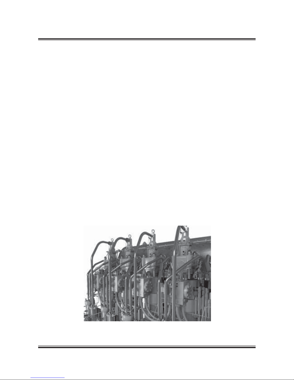
and gas burning engines, the ME-GI engine provides optimal fuel flexibility. Fig. 1.00.01 shows the
components that are modified and added to the
engine, allowing it to operate on gas.
The new units are:
• A chain pipe gas supply system for high-pressure gas distribution to a gas control block on
each cylinder
• Leakage detection and ventilation system for
venting the space between the inner and outer
pipe of the double-wall piping and detecting
leakages. Inlet air is taken from a non-hazardous
area and exhausted to outside the engine room
• Sealing oil system, delivering sealing oil to the
gas valves separating control oil and gas. Fully
integrated on the engine, the shipyard does not
need to consider this installation
• Inert gas system that enables purging of the gas
system on the engine with inert gas
The development in gas and fuel oil prices in
combination with the emission control regulations,
has created a need for dual fuel engines.
The ME-GI engine is designed as an add-on to
the MAN B&W two-stroke ME engine technology.
It allows the engine to run on either heavy fuel oil
(HFO) or liquid natural gas (LNG).
ME-GI injection system
Dual fuel operation requires the injection of first
pilot fuel (to start the combustion) and then gas
fuel into the combustion chamber.
Different types of valves are used for the injection
of gas and pilot fuel. The auxiliary media required
for both fuel and gas operation is:
• High-pressure gas
• Fuel oil (pilot oil by existing ME fuel oil system)
• Control oil for actuation of gas injection valves
• Sealing oil to separate gas and control oil.
Fig. 1.00.01: Gas module with chain pipes, gas control block and fuel gas double-wall high-pressure pipes
178 65 951.0
Page 14

MAN B&W 1.00
Page 2 of 2
MAN Diesel
MAN B&W M E-GI engines
198 91 51-6.1
• Control and safety system, comprising
a hydrocarbon analyser for checking the
hydrocarbon content of the air in the doublewall gas pipes.
Engine operating modes
One main advantage of the ME-GI engine is its
fuel flexibility. The control concept comprises
three different fuel modes, see Fig. 1.00.02:
• gas operation with minimum pilot oil amount
• specified dual fuel operation (SDF) with injection
of a fixed gas amount
• fuel-oil-only mode.
Gas operation mode is used for gas operation.
It can only be started manually by an operator on
the Main Operating Panel (MOP) in the control
room. The minimum preset amount of pilot fuel oil
is as little as 3% at SMCR.
Specified dual fuel operation (SDF) mode gives
the operator full fuel flexibility and the option to
inject a fixed amount of gas fuel. The ME control
system adds fuel oil until the required engine load
is reached.
Fuel-oil-only mode is known from the ME engine.
Operating the engine in this mode can only be
done on fuel oil. In this mode, the engine is considered ‘gas safe’. If a failure in the gas system
occurs, it results in a gas shutdown and a return
to the fuel-oil only mode.
Safety
The ME-GI control and safety system is designed
to fail to safe condition. All failures detected during gas fuel running result in a gas fuel stop and
a change-over to fuel oil operation. This condition
applies also to failures of the control system itself.
Following the change-over, the high-pressure gas
pipes and the complete gas supply system are
blown-out and freed from gas by purging.
The change-over to fuel oil mode is always done
without any power loss of the engine.
Fuel gas supply systems
Different applications call for different gas supply
systems, and operators and shipowners demand
alternative solutions.
Therefore, MAN Diesel & Turbo aims to have a
number of different gas supply systems prepared,
tested and available. Examples of fuel gas supply
systems are presented in Section 7.08.Fig. 1.00.02: Fuel type modes for the ME-GI engines for
LNG carriers
0 1020304050
Engine load (%SMCR)
% Fuel% Fuel
60 70 80 90 100
100%
90%
80%
70%
60%
50%
40%
30%
20%
10%
0%
0 1020304050
Engine load (%SMCR)
60 70 80 90 100
100%
90%
80%
70%
60%
50%
40%
30%
20%
10%
0%
Gas operation mode
Specified dual fuel operation mode
% Total
% Pilot
% Total
% Pilot
178 65 963.1
Page 15

MAN B&W 1.01
Page 1 of 2
MAN Diesel
198 85 37-1.4MAN B&W 9 8ME/ME- C7-TII .1,
95-40ME-C/-GI-TII .5/.4/.2 engines
The ever valid requirement of ship operators is
to obtain the lowest total operational costs, and
especially the lowest possible specific fuel oil
consumption at any load, and under the prevailing
operating conditions.
However, lowspeed twostroke main engines
of the MC-C type, with a chain driven camshaft,
have limited flexibility with regard to fuel injection
and exhaust valve activation, which are the two
most important factors in adjusting the engine to
match the prevailing operating conditions.
A system with electronically controlled hydraulic
activation provides the required flexibility, and
such systems form the core of the ME Engine
Control System, described later in detail in Chapter 16.
Concept of the ME engine
The ME engine concept consists of a hydraulicmechanical system for activation of the fuel injection and the exhaust valves. The actuators are
electronically controlled by a number of control
units forming the complete Engine Control System.
MAN Diesel & Turbo has specifically developed
both the hardware and the software inhouse, in
order to obtain an integrated solution for the Engine Control System.
The fuel pressure booster consists of a simple
plunger powered by a hydraulic piston activated
by oil pressure. The oil pressure is controlled by
an electronically controlled proportional valve.
The exhaust valve is opened hydraulically by
means of a twostage exhaust valve actuator
activated by the control oil from an electronically
controlled proportional valve. The exhaust valves
are closed by the ‘air spring’.
In the hydraulic system, the normal lube oil is used
as the medium. It is filtered and pressurised by a
Hydraulic Power Supply unit mounted on the engine or placed in the engine room.
The starting valves are opened pneumatically by
electronically controlled ‘On/Off’ valves, which
make it possible to dispense with the mechanically activated starting air distributor.
By electronic control of the above valves according to the measured instantaneous crankshaft position, the Engine Control System fully controls the
combustion process.
System flexibility is obtained by means of different
‘Engine running modes’, which are selected either
automatically, depending on the operating conditions, or manually by the operator to meet specific
goals. The basic running mode is ‘Fuel economy
mode’ to comply with IMO NOx emission limitation.
Engine design and IMO regulation compliance
The ME-C engine is the shorter, more compact
version of the ME engine. It is well suited wherever
a small engine room is requested, for instance in
container vessels.
For MAN B&W ME/ME-C-TII designated engines,
the design and performance parameters comply
with the International Maritime Organisation (IMO)
Tier II emission regulations.
For engines built to comply with IMO Tier I emission regulations, please refer to the Marine Engine
IMO Tier I Project Guide.
The Fuel Optimised ME Tier II Engine
Page 16

MAN B&W 1.01
Page 2 of 2
MAN Diesel
198 91 58 -9.0
MAN B&W M E-GI/ME-C- GI TII engines . 2 and higher
Tier II fuel optimisation
NOx regulations place a limit on the SFOC on
two-stroke engines. In general, NOx emissions will
increase if SFOC is decreased and vice versa. In
the standard configuration, MAN B&W engines are
optimised close to the IMO NOx limit and, therefore, NOx emissions may not be further increased.
The IMO NOx limit is given as a weighted average
of the NOx emission at 25, 50, 75 and 100% load.
This relationship can be utilised to tilt the SFOC
profile over the load range. This means that SFOC
can be reduced at part load or low load at the
expense of a higher SFOC in the high-load range
without exceeding the IMO NOx limit.
Improved fuel consumption on gas fuel
In the ME-GI concept, NOx is reduced substantially on gas fuel compared to diesel/HFO operation. As much as possible of this NOx margin is
exchanged for improved SFOC, while not exceeding the E3 NOx cycle value for the diesel reference
case.
The SFOC optimisation is carried out in the partload range from 75% load and below. Further to
this SFOC improvement on gas, no other part- or
low-load optimisation methods are applicable for
the ME-GI engine.
In this project guide, data is based on high-load
optimisation unless explicitly noted. For derated
engines, calculations can be made in the CEAS
application described in Section 20.02.
Page 17
MAN B&W MC/MC-C, ME/MEC/MEB/-GI engines 198 38 24 3.9
MAN B&W 1.02
Page 1 of 1
MAN Diesel
Engine Type Designation
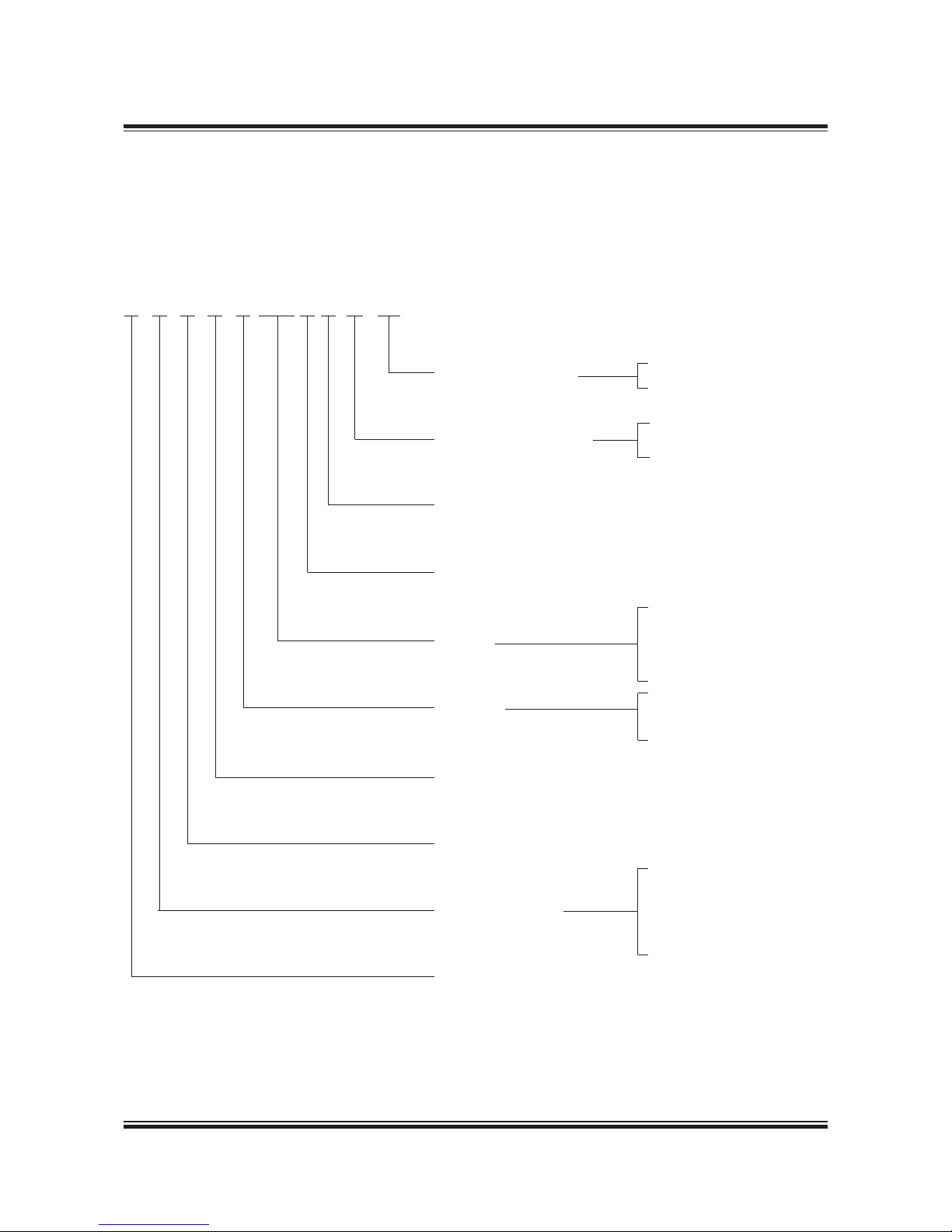
6 S 90 M E C 9 .2 -GI -TII
Engine programme
Diameter of piston in cm
G ‘Green’ Ultra long stroke
S Super long stroke
L Long stroke
K Short stroke
Stroke/bore ratio
Number of cylinders
Concept
E Electronically controlled
C Camshaft controlled
Fuel injection concept
(blank) Fuel oil only
GI Gas injection
Emission regulation
TII IMO Tier level
Design
C Compact engine
B Exhaust valve controlled
by camshaft
Mark number
Version number
Page 18

MAN B&W 1.03
Page 1 of 1
MAN Diesel
198 89 87-5. 0MAN B&W S 65ME-C8. 2-GI-TII
Power, Speed and Fuel Oil
MAN B&W S65ME-C8.2-GI-TII
Fig 1.03.01: Power, speed and fuel
kW/cyl.
r/min
L
1
L
2
2,870
2,450
2,290
1,960
81 95
L
3
L
4
Cyl. L1 kW Stroke: 2,730 mm
5 14,350
6 17,220
7
8
SFOC gas engines [g/kWh]
L1/L3 MEP: 20.0 bar – L2/L4 MEP: 16.0 bar
50% 75% 100%
Gas and pilot fuel
M,MI
L
1
164.5 162.0 168.0
L
2
160.5 156.0 162.0
L
3
164.5 162.5 168.0
L
4
160.5 156.5 162.0
Liquid fuel only
M,MI
L1/ L
3
167.5 165.0
L2/ L
4
163.5 163.0
5RGEKǣEICUCPFRKNQVHWGNEQPUWORVKQPEQPUKUVUQHRKNQVNKSWKFHWGNCPFICUHWGN
)CUHWGN.%8M,MIKUEQPXGTVGFVQFKGUGNHWGN.%8M,MIHQTEQORCTKUQP
YKVJFKGUGNGPIKPG
Distributed fuel data [g/kWh]
50% 75% 100%
Gas fuel
M,MI
L
1
133.7 133.1
L
2
128.5 126.7 133.0
L
3
133.7 133.6
L
4
128.5 127.1 133.0
Pilot fuel
M,MI
L1/ L
3
8.0 6.1 5.0
L2/ L
4
10.0 7.7 6.3
Page 19

MAN B&W 1.04
Page 1 of 2
MAN Diesel
MAN B&W M E-GI engines
198 49 17-2.4
Engine Power Range and Fuel Oil Consumption
0OWER
3PEED
,
,
,
,
Specific Fuel Oil Consumption (SFOC)
The figures given in this folder represent the values obtained when the engine and turbocharger
are matched with a view to obtaining the lowest
possible SFOC values while also fulfilling the IMO
NOX Tier II emission limitations.
Stricter emission limits can be met on request, using proven technologies.
The SFOC figures are given in g/kWh with a tolerance of 5% and are based on the use of fuel with
a lower calorific value of 42,700 kJ/kg (~10,200
kcal/
kg) at ISO conditions:
Ambient air pressure ............................. 1,000 mbar
Ambient air temperature ................................ 25 °C
Cooling water temperature ............................ 25 °C
Specific fuel oil consumption varies with ambient
conditions and fuel oil lower calorific value. For
calculation of these changes, see Chapter 2.
Gas consumption
The energy consumption (heat rate) for the GI
engine is lower when running on gas in dual fuel
mode (heat rate in kJ/kWh) compared to fuel only
mode.
When a given amount of oil is known in g/kWh,
and after deducting the pilot fuel oil the additional
gas consumption can be found by converting the
energy supplied as gas into cubic metre per hour
according to the LCV of the gas.
In the following sections, the energy consumption
is calculated as related equivalent fuel consumption, i.e. with all our usual figures.
Example:
Related equivalent SFOC og gas .......... 169 g/kWh
Ref. LCV .................................................. 42,700 kJ
Heat rate .................0.169 x 42,700 = 7,216 kJ/kWh
The heat rate is also referred to as the ‘Guiding
Equivalent Energy Consumption’.
Engine Power
The following tables contain data regarding the
power, speed and specific fuel oil consumption of
the engine.
Engine power is specified in kW for each cylinder
number and layout points L1, L2, L3 and L4:
For conversions between kW and metric horsepower, please note that 1 BHP = 75 kpm/s = 0.7355
kW.
L1 designates nominal maximum continuous rating
(nominal MCR), at 100% engine power and 100%
engine speed.
L2, L3 and L4 designate layout points at the other
three corners of the layout area, chosen for easy
reference.
Fig. 1.04.01: Layout diagram for engine power and speed
Overload corresponds to 110% of the power at
MCR, and may be permitted for a limited period of
one hour every 12 hours.
The engine power figures given in the tables remain valid up to tropical conditions at sea level as
stated in IACS M28 (1978), i.e.:
Blower inlet temperature ................................ 45 °C
Blower inlet pressure ............................1,000 mbar
Seawater temperature .................................... 32 °C
Relative humidity ..............................................60%
178 51 489.0
Page 20

MAN B&W 1.04
Page 2 of 2
MAN Diesel
MAN B&W M E-GI engines
198 49 17-2.4
Lubricating oil data
The cylinder oil consumption figures stated in the
tables are valid under normal conditions.
During runningin periods and under special conditions, feed rates can be increased. This is explained
in Section 9.02.
Page 21

MAN B&W
Page 1 of 1
MAN Diesel
198 53 31-6 .2MAN B &W MC/MC-C, ME /ME-C/MEB /GI eng ines
Performance Curves
1.0 5
Updated engine and capacities data is available
from the CEAS program on www.marine.man.eu
→ ’Two-Stroke’ → ’CEAS Engine Calculations’.
Page 22

MAN B&W 1.06
Page 1 of 7
MAN Diesel
198 89 14-5. 2MAN B& W 90-50ME- C8-GI TII .2 an d higher
Please note that engines built by our licensees are
in accordance with MAN Diesel & Turbo drawings
and standards but, in certain cases, some local
standards may be applied; however, all spare parts
are interchangeable with MAN Diesel & Turbo designed parts.
Some components may differ from MAN Diesel &
Turbo’s design because of local production facilities or the application of local standard components.
In the following, reference is made to the item
numbers specified in the ‘Extent of Delivery’ (EoD)
forms, both for the ‘Basic’ delivery extent and for
some ‘Options’.
Bedplate and Main Bearing
The bedplate is made with the thrust bearing in
the aft end of the engine. The bedplate consists
of high, welded, longitudinal girders and welded
cross girders with cast steel bearing supports.
For fitting to the engine seating in the ship, long,
elastic holdingdown bolts, and hydraulic tightening tools are used.
The bedplate is made without taper for engines
mounted on epoxy chocks.
The oil pan, which is made of steel plate and is
welded to the bedplate, collects the return oil from
the forced lubricating and cooling oil system. The
oil outlets from the oil pan are vertical as standard
and provided with gratings.
The main bearings consist of thin walled steel
shells lined with bearing metal. The main bearing
bottom shell can be rotated out and in by means
of special tools in combination with hydraulic tools
for lifting the crankshaft. The shells are kept in position by a bearing cap.
Frame Box
The frame box is of welded design. On the exhaust side, it is provided with relief valves for each
cylinder while, on the manoeuvring side, it is provided with a large hinged door for each cylinder.
The crosshead guides are welded on to the frame
box.
The frame box is bolted to the bedplate. The bedplate, frame box and cylinder frame are tightened
together by stay bolts.
Cylinder Frame and Stuffing Box
The cylinder frame is cast and provided with access covers for cleaning the scavenge air space,
if required, and for inspection of scavenge ports
and piston rings from the manoeuvring side. Together with the cylinder liner it forms the scavenge
air space.
The cylinder frame is fitted with pipes for the piston cooling oil inlet. The scavenge air receiver, turbocharger, air cooler box and gallery brackets are
located on the cylinder frame. At the bottom of the
cylinder frame there is a piston rod stuffing box,
provided with sealing rings for scavenge air, and
with oil scraper rings which prevent crankcase oil
from coming up into the scavenge air space.
Drains from the scavenge air space and the piston
rod stuffing box are located at the bottom of the
cylinder frame.
Cylinder Liner
The cylinder liner is made of alloyed cast iron and
is suspended in the cylinder frame. The top of the
cylinder liner is fitted with a cooling jacket. The
cylinder liner has scavenge ports and drilled holes
for cylinder lubrication.
Cylinder liners prepared for installation of temperature sensors is basic execution on engines type
90 while an option on all other engines.
ME-GI Engine Description
Page 23

MAN B&W 1.06
Page 2 of 7
MAN Diesel
198 89 14-5. 2MAN B& W 90-50ME- C8-GI TII .2 an d higher
Cylinder Cover
The cylinder cover is of forged steel, made in one
piece, and has bores for cooling water. It has a
central bore for the exhaust valve, and bores for
the fuel valves, gas valves, a starting valve and an
indicator valve.
The side of the cylinder cover facing the hydraulic cylinder unit (HCU) block has a face for the
mounting of a special valve block, the Gas Control
Block, see later description.
In addition, the cylinder cover is provided with one
set of bores for supplying gas from the gas control block to each gas injection valve.
Crankshaft
The crankshaft is of the semibuilt type, made
from forged or cast steel throws. For engines with
9 cylinders or more, the crankshaft is supplied in
two parts.
At the aft end, the crankshaft is provided with the
collar for the thrust bearing, a flange for fitting the
gear wheel for the stepup gear to the hydraulic
power supply unit if fitted on the engine, and the
flange for the turning wheel and for the coupling
bolts to an intermediate shaft.
At the front end, the crankshaft is fitted with the
collar for the axial vibration damper and a flange
for the fitting of a tuning wheel. The flange can
also be used for a Power Take Off, if so desired.
Coupling bolts and nuts for joining the crankshaft
together with the intermediate shaft are not normally supplied.
Thrust Bearing
The propeller thrust is transferred through the
thrust collar, the segments, and the bedplate, to
the end chocks and engine seating, and thus to
the ship’s hull.
The thrust bearing is located in the aft end of the
engine. The thrust bearing is of the B&WMichell
type, and consists primarily of a thrust collar on
the crankshaft, a bearing support, and segments
of steel lined with white metal.
Engines type 60 and larger with 9 cylinders or
more will be specified with the 360º degree type
thrust bearing, while the 240º degree type is used
in all other engines. MAN Diesel & Turbo’s flexible
thrust cam design is used for the thrust collar on a
range of engine types.
The thrust shaft is an integrated part of the crankshaft and it is lubricated by the engine’s lubricating oil system.
Stepup Gear
In case of mechanically, engine driven Hydraulic
Power Supply, the main hydraulic oil pumps are
driven from the crankshaft via a stepup gear. The
stepup gear is lubricated from the main engine
system.
Turning Gear and Turning Wheel
The turning wheel is fitted to the thrust shaft, and
it is driven by a pinion on the terminal shaft of the
turning gear, which is mounted on the bedplate.
The turning gear is driven by an electric motor
with builtin brake.
A blocking device prevents the main engine from
starting when the turning gear is engaged. Engagement and disengagement of the turning gear
is effected manually by an axial movement of the
pinion.
The control device for the turning gear, consisting
of starter and manual control box, can be ordered
as an option.
Page 24

MAN B&W 1.06
Page 3 of 7
MAN Diesel
198 89 14-5. 2MAN B& W 90-50ME- C8-GI TII .2 an d higher
Axial Vibration Damper
The engine is fitted with an axial vibration damper,
mounted on the fore end of the crankshaft. The
damper consists of a piston and a splittype housing located forward of the foremost main bearing.
The piston is made as an integrated collar on the
main crank journal, and the housing is fixed to the
main bearing support.
For functional check of the vibration damper a
mechanical guide is fitted, while an electronic vibration monitor can be supplied as an option.
Tuning Wheel / Torsional Vibration Damper
A tuning wheel or torsional vibration damper may
have to be ordered separately, depending on the
final torsional vibration calculations.
Connecting Rod
The connecting rod is made of forged or cast
steel and provided with bearing caps for the
crosshead and crankpin bearings.
The crosshead and crankpin bearing caps are
secured to the connecting rod with studs and nuts
tightened by means of hydraulic jacks.
The crosshead bearing consists of a set of
thinwalled steel shells, lined with bearing metal.
The crosshead bearing cap is in one piece, with
an angular cutout for the piston rod.
The crankpin bearing is provided with thinwalled
steel shells, lined with bearing metal. Lube oil is
supplied through ducts in the crosshead and connecting rod.
Piston
The piston consists of a piston crown and piston
skirt. The piston crown is made of heatresistant
steel. A piston cleaning ring located in the very
top of the cylinder liner scrapes off excessive ash
and carbon formations on the piston topland.
The piston has four ring grooves which are
hardchrome plated on both the upper and lower
surfaces of the grooves. The uppermost piston
ring is of the CPR type (Controlled Pressure Relief), whereas the other three piston rings all have
an oblique cut. The uppermost piston ring is higher than the others. All four rings are alu-coated on
the outer surface for running-in.
The piston skirt is made of cast iron with a bronze
band or Mo coating.
Piston Rod
The piston rod is of forged steel and is surfacehardened on the running surface for the stuffing
box. The piston rod is connected to the crosshead
with four bolts. The piston rod has a central bore
which, in conjunction with a cooling oil pipe, forms
the inlet and outlet for cooling oil.
Crosshead
The crosshead is of forged steel and is provided
with cast steel guide shoes with white metal on
the running surface. The guide shoe is of the low
friction type and crosshead bearings of the wide
pad design.
The telescopic pipe for oil inlet and the pipe for oil
outlet are mounted on the guide shoes.
Scavenge Air System
The air intake to the turbocharger takes place
directly from the engine room through the turbocharger intake silencer. From the turbocharger,
the air is led via the charging air pipe, air cooler
and scavenge air receiver to the scavenge ports
of the cylinder liners, see Chapter 14. The scavenge air receiver on engines type 65 is of the Dshape design.
Page 25

MAN B&W 1.06
Page 4 of 7
MAN Diesel
198 89 14-5. 2MAN B& W 90-50ME- C8-GI TII .2 an d higher
Scavenge Air Cooler
For each turbocharger is fitted a scavenge air
cooler of the monoblock type designed for seawater cooling, alternatively, a central cooling system with freshwater can be chosen. The working
pressure is up to 4.5 bar.
The scavenge air cooler is so designed that the
difference between the scavenge air temperature
and the water inlet temperature at specified MCR
can be kept at about 12 °C.
Auxiliary Blower
The engine is provided with electricallydriven
scavenge air blowers integrated in the scavenge
air cooler. The suction side of the blowers is connected to the scavenge air space after the air
cooler.
Between the air cooler and the scavenge air receiver, nonreturn valves are fitted which automatically close when the auxiliary blowers supply
the air.
The auxiliary blowers will start operating consecutively before the engine is started in order to
ensure sufficient scavenge air pressure to obtain a
safe start.
Further information is given in Chapter 14.
Exhaust Gas System
From the exhaust valves, exhaust gas is led to
the exhaust gas receiver where the fluctuating
pressure from the individual cylinders is equalised, and the total volume of gas is led to the
turbocharger(s). After the turbocharger(s), the gas
is led to the external exhaust pipe system.
Compensators are fitted between the exhaust
valves and the receiver, and between the receiver
and the turbocharger(s).
The exhaust gas receiver and exhaust pipes are
provided with insulation, covered by galvanised
steel plating.
A protective grating is installed between the exhaust gas receiver and the turbocharger.
Exhaust Turbocharger
The engines can be fitted with either MAN, ABB or
MHI turbochargers. As an option, MAN TCA turbochargers can be delivered with variable nozzle
technology that reduces the fuel consumption at
part load by controlling the scavenge air pressure.
The turbocharger selection is described in Chapter 3, and the exhaust gas system in Chapter 15.
Reversing
Reversing of the engine is performed electronically and controlled by the Engine Control System,
by changing the timing of the fuel injection, the
exhaust valve activation and the starting valves.
The Hydraulic Power Supply
The Hydraulic Power Supply (HPS) filters and
pressurises the lube oil for use in the hydraulic
system. The HPS consists of either mechanically
driven (by the engine) main pumps with electrically
driven start-up pumps or electrically driven combined main and start-up pumps. The hydraulic
pressure varies up to max 300 bar.
The mechanically driven HPS is engine driven and
mounted aft for engines with chain drive aft (8 cylinders or less), and at the middle for engines with
chain drive located in the middle (9 cylinders or
more). An electrically driven HPS is usually mounted aft on the engine.
A combined HPS, mechanically driven with electrically driven start-up/back-up pumps with backup capacity, is available as an option for engines
type 90-60 while basic execution for type 50.
Page 26

MAN B&W 1.06
Page 5 of 7
MAN Diesel
198 89 14-5. 2MAN B& W 90-50ME- C8-GI TII .2 an d higher
Hydraulic Cylinder Unit
The hydraulic cylinder unit (HCU), one per cylinder, consists of a base plate on which a distributor
block is mounted. The distributor block is fitted
with a number of accumulators to ensure that the
necessary hydraulic oil peak flow is available for
the electronically controlled fuel injection.
The distributor block serves as a mechanical
support for the hydraulically activated fuel oil
pressure booster and the hydraulically activated
exhaust valve actuator.
Fuel Oil Pressure Booster and
Fuel Oil High Pressure Pipes
The engine is provided with one hydraulically activated fuel oil pressure booster for each cylinder.
Injection of fuel oil (pilot oil) is activated by a multiway valve (FIVA) while injection of fuel gas is activated by the ELGI valve. Both valves are electronically controlled by the Cylinder Control Unit (CCU)
of the Engine Control System.
The fuel oil highpressure pipes are of the doublewall type with built-in conical support. The pipes
are insulated but not heated.
Further information is given in Section 7.00.
Gas Pipes
A chain pipe system is fitted for high-pressure
gas distribution to each adapter block. The chain
pipes are connected to the gas control block via
the adapter block.
Gas pipes are designed with double walls, with
the outer shielding pipe designed so as to prevent
gas outflow to the machinery spaces in the event
of leaking or rupture of the inner gas pipe.
The intervening gas pipe space, including also the
space around valves, flanges, etc., is vented by
separate mechanical ventilation with a capacity of
30 air changes per hour. Any leakage gas will be
led to the ventilated part of the double-wall piping
system and will be detected by HC sensors.
The pressure in the intervening space is kept below that of the engine room. The extractor fan motor is placed outside the duct and the machinery
space. The ventilation inlet air must be taken from
a gas safe area and exhausted to a safe place.
The gas pipes on the engine are designed for and
pressure tested at 50% higher pressure than the
normal working pressure, and are supported so
as to avoid mechanical vibrations. The gas pipes
should furthermore be protected against drops of
heavy items.
The chain piping to the individual cylinders are
flexible enough to cope with the mechanical stress
from the thermal expansion of the engine from
cold to hot condition. The chain pipes are connected to the gas control blocks by means of adapter
blocks.
The gas pipe system is designed so as to avoid
excessive gas pressure fluctuations during operation.
The gas pipes are to be connected to an inert gas
purging system.
Gas Control Block
The gas control block consists of a square steel
block, bolted to the HCU side of the cylinder
cover.
The gas control block incorporates a large volume
accumulator and is provided with a window/shutdown valve, a purge valve and a blow-off valve. All
high-pressure gas sealings lead into spaces that
are connected to the double-wall pipe system, for
leakage detection.
Minute volumes around the gas injection valves in
the cylinder cover are kept under vacuum from the
venting air in the double-wall gas pipes.
Internal bores connect the hydraulic oil, sealing
oil and the gas to the various valves. A non-return
valve is positioned at the gas inlet to the gas accumulator, in order to ensure that gas cannot flow
backwards in the system.
Page 27

MAN B&W 1.06
Page 6 of 7
MAN Diesel
198 89 14-5. 2MAN B& W 90-50ME- C8-GI TII .2 an d higher
An ELGI and ELWI valve and control oil supply are
also incorporated in the gas control block.
The gas pressure in the channel between the gas
injection valve and the window valve is measured.
The pressure measuring is used to monitor the
function of and to detect a leaking window valve,
gas-injection valve or blow-off valve.
Any larger pressure increase would indicate a severe leakage in the window/shut down valve and a
pressure decrease would indicate a severe leakage in the gas injection valve seats or in the blowoff valve. The safety system will detect this and
shut down the gas injection.
From the accumulator, the gas passes through a
bore in the gas control block to the window valve,
which in the gas mode is opening and closing
in each cycle by hydraulic oil. From the window/
shutdown valve, the gas is led to the gas injection
valve via bores in the gas control block and in the
cylinder cover. A blow-off valve placed on the gas
control block is designed to empty the gas bores
during gas standby or gas stop.
A purge valve, also placed on the gas control
block, is designed to empty the accumulator when
the engine is no longer to operate in the gas mode.
Both hydraulically actuated blow-off and purge
valves are also utilised during inert gas purging,
all controlled by the gas injection engine control
system (ME-GI-ECS).
Fuel Valves, Gas Valves and Starting Air Valve
The cylinder cover is equipped with two or three
fuel valves, two or three gas valves, a starting air
valve and an indicator cock.
The opening of the fuel valves is controlled by the
high pressure fuel oil created by the fuel oil pressure booster, and the valves are closed by a spring.
The opening of the gas valves is controlled by the
ELGI valve, which operates on control oil taken
from the system oil.
An automatic vent slide allows circulation of fuel
oil through the valve and the high pressure pipes
when the engine is stopped. The vent slide also
prevents the compression chamber from being
filled up with fuel oil in the event that the valve
spindle sticks. Oil from the vent slide and other
drains is led away in a closed system.
Supply of starting air is provided by one solenoid
valve per cylinder, controlled by the CCUs of the
Engine Control System.
The starting valve is opened by control air, timed
by the Engine Control System, and is closed by a
spring.
Slow turning before starting is a program incorporated in the basic Engine Control System.
The starting air system is described in detail in
Section 13.01.
Exhaust Valve
The exhaust valve consists of the valve housing
and the valve spindle. The valve housing is made
of cast iron and is arranged for water cooling. The
housing is provided with a water cooled bottom
piece of steel with a flame hardened seat. The
exhaust valve spindle is a DuraSpindle (Nimonic
on S80 and engines type 65-50, however) and the
housing provided with a spindle guide.
The exhaust valve is tightened to the cylinder
cover with studs and nuts. The exhaust valve is
opened hydraulically by the electronic valve activation system and is closed by means of air pressure.
The operation of the exhaust valve is controlled by
the FIVA valve, which also activates the fuel injection.
In operation, the valve spindle slowly rotates, driven by the exhaust gas acting on small vanes fixed
to the spindle.
Page 28

MAN B&W 1.06
Page 7 of 7
MAN Diesel
198 89 14-5. 2MAN B& W 90-50ME- C8-GI TII .2 an d higher
Sealing of the exhaust valve spindle guide is provided by means of Controlled Oil Level (COL), an
oil bath in the bottom of the air cylinder, above the
sealing ring. This oil bath lubricates the exhaust
valve spindle guide and sealing ring as well.
Indicator Cock
The engine is fitted with an indicator cock to
which the PMI pressure transducer is connected.
MAN B&W Alpha Cylinder Lubrication
The electronically controlled MAN B&W Alpha
cylinder lubrication system is applied to the ME
engines, and controlled by the ME Engine Control
System.
The main advantages of the MAN B&W Alpha cylinder lubrication system, compared with the conventional mechanical lubricator, are:
• Improved injection timing
• Increased dosage flexibility
• Constant injection pressure
• Improved oil distribution in the cylinder liner
• Possibility for prelubrication before starting.
More details about the cylinder lubrication system
can be found in Chapter 9.
Gallery Arrangement
The engine is provided with gallery brackets,
stanchions, railings and platforms (exclusive of
ladders). The brackets are placed at such a height
as to provide the best possible overhauling and
inspection conditions.
Some main pipes of the engine are suspended
from the gallery brackets, and the topmost gallery
platform on the manoeuvring side is provided with
overhauling holes for the pistons.
The engine is prepared for top bracings on the exhaust side, or on the manoeuvring side.
Piping Arrangements
The engine is delivered with piping arrangements
for:
• Fuel oil
• High pressure gas supply
• Heating of fuel oil
• Lubricating oil, piston cooling oil, hydraulic oil
and sealing oil for gas valves
• Cylinder lubricating oil
• Cooling water to scavenge air cooler
• Jacket and turbocharger cooling water
• Cleaning of turbocharger
• Fire extinguishing in scavenge air space
• Starting air
• Control air
• Oil mist detector (required only for make
Schaller Automation)
• Various drain pipes.
All piping arrangements are made of steel piping,
except the control air and steam heating of fuel
pipes, which are made of copper.
The pipes are provided with sockets for local
instruments, alarm and safety equipment and,
furthermore, with a number of sockets for supplementary signal equipment. Chapter 18 deals with
the instrumentation.
Page 29

MAN B&W
MAN Diesel
Engine Layout and Load
Diagrams, SFOC
2
Page 30

Page 31
MAN B&W 2.01
Page 1 of 2
MAN Diesel
198 38 33 8.5MA N B&W MC/MCC , ME/ME GI/ME-B eng ines
Engine Layout and Load Diagrams
Introduction
The effective power ‘P’ of a diesel engine is proportional to the mean effective pressure pe and
engine speed ‘n’, i.e. when using ‘c’ as a constant:
P = c × pe × n
so, for constant mep, the power is proportional to
the speed:
P = c × n1 (for constant mep)
When running with a Fixed Pitch Propeller (FPP),
the power may be expressed according to the
propeller law as:
P = c × n
3
(propeller law)
Thus, for the above examples, the power P may
be expressed as a power function of the speed ‘n’
to the power of ‘i’, i.e.:
P = c × n
i
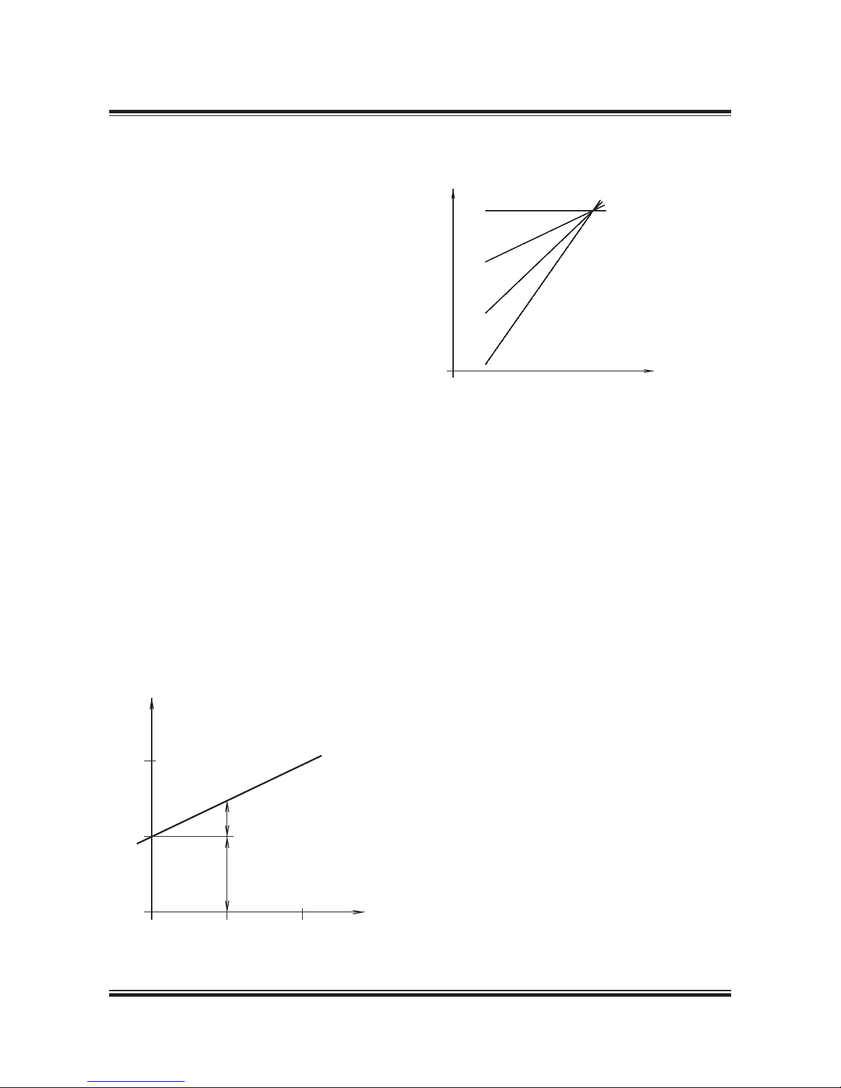
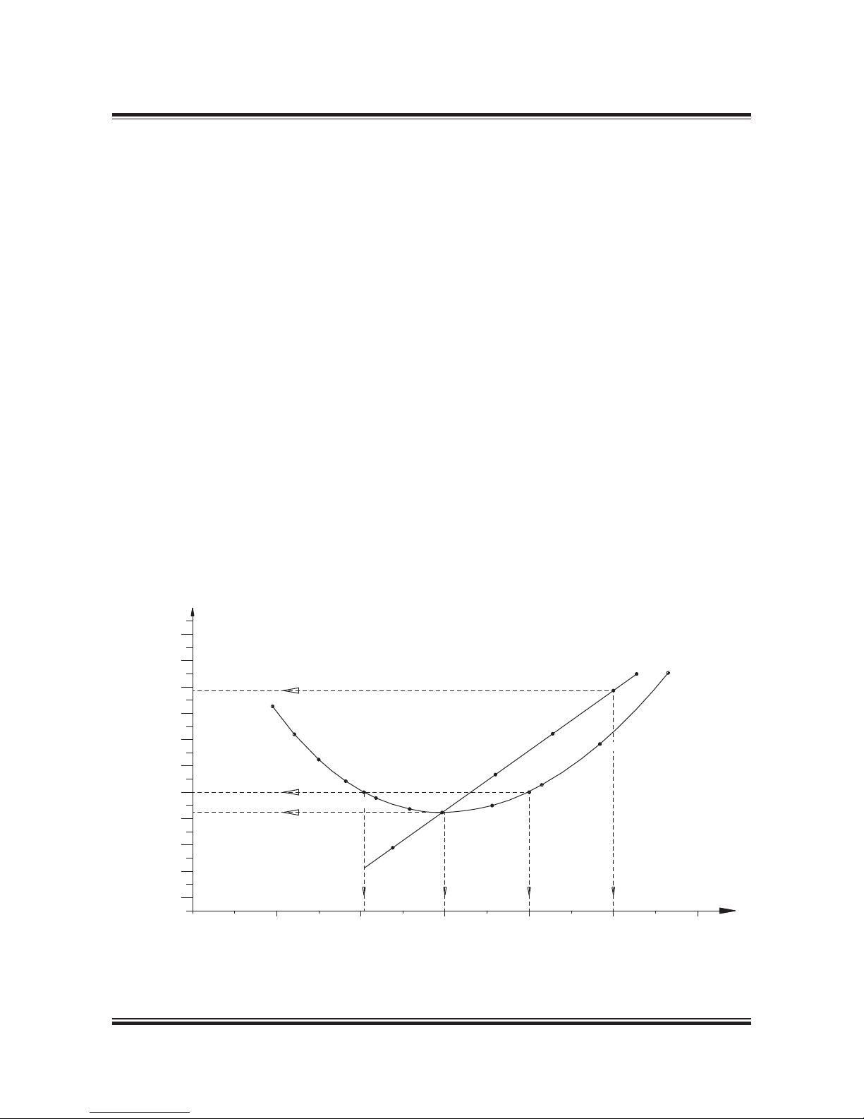
Fig. 2.01.01 shows the relationship for the linear
functions, y = ax + b, using linear scales.
The power functions P = c × ni will be linear functions when using logarithmic scales:
log (P) = i × log (n) + log (c)
Fig. 2.01.01: Straight lines in linear scales
Fig. 2.01.02: Power function curves in logarithmic scales
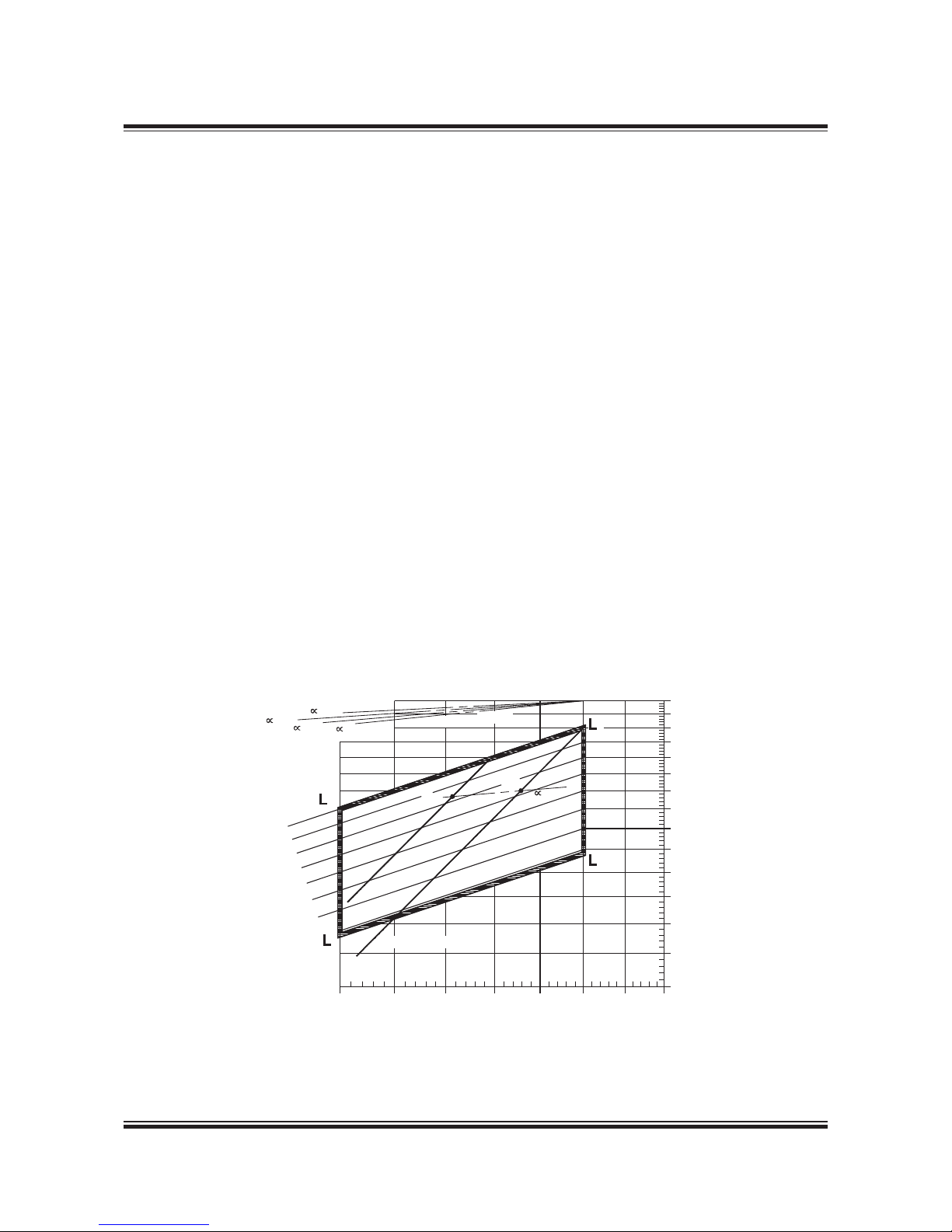
Thus, propeller curves will be parallel to lines having the inclination i = 3, and lines with constant
mep will be parallel to lines with the inclination i = 1.
Therefore, in the Layout Diagrams and Load Diagrams for diesel engines, logarithmic scales are
used, giving simple diagrams with straight lines.
Propulsion and Engine Running Points
Propeller curve
The relation between power and propeller speed
for a fixed pitch propeller is as mentioned above
described by means of the propeller law, i.e. the
third power curve:
P = c × n3, in which:
P = engine power for propulsion
n = propeller speed
c = constant
Propeller design point
Normally, estimates of the necessary propeller
power and speed are based on theoretical calculations for loaded ship, and often experimental
tank tests, both assuming optimum operating
conditions, i.e. a clean hull and good weather. The
combination of speed and power obtained may
be called the ship’s propeller design point (PD),
178 05 403.0
178 05 403.1
y
2
1
0
0
12
b
a
y=ax+b
x
y=log(P)
i = 0
i = 1
i = 2
i = 3
P = n x c
i
log (P) = i x log (n) + log (c)
x = log (n)
Page 32
MAN B&W 2.01
Page 2 of 2
MAN Diesel
198 38 33 8.5MA N B&W MC/MCC , ME/ME GI/ME-B eng ines
placed on the light running propeller curve 6. See
below figure. On the other hand, some shipyards,
and/or propeller manufacturers sometimes use a
propeller design point (PD) that incorporates all or
part of the socalled sea margin described below.
the socalled sea margin, which is traditionally
about 15% of the propeller design (PD) power.
Engine layout (heavy propeller)
When determining the necessary engine layout
speed that considers the influence of a heavy running propeller for operating at high extra ship resistance, it is (compared to line 6) recommended to
choose a heavier propeller line 2. The propeller
curve for clean hull and calm weather line 6 may
then be said to represent a ‘light running’ (LR)
propeller.
Compared to the heavy engine layout line 2, we
recommend using a light running of 3.07.0% for
design of the propeller.
Engine margin
Besides the sea margin, a socalled ‘engine margin’ of some 10% or 15% is frequently added. The
corresponding point is called the ‘specified MCR
for propulsion’ (MP), and refers to the fact that the
power for point SP is 10% or 15% lower than for
point MP.
Point MP is identical to the engine’s specified
MCR point (M) unless a main engine driven shaft
generator is installed. In such a case, the extra
power demand of the shaft generator must also
be considered.
Constant ship speed lines
The constant ship speed lines
∝, are shown at
the very top of the figure. They indicate the power
required at various propeller speeds in order to
keep the same ship speed. It is assumed that, for
each ship speed, the optimum propeller diameter
is used, taking into consideration the total propulsion efficiency. See definition of
∝ in Section 2.02.
Note:
Light/heavy running, fouling and sea margin are
overlapping terms. Light/heavy running of the
propeller refers to hull and propeller deterioration
and heavy weather, whereas sea margin i.e. extra
power to the propeller, refers to the influence of
the wind and the sea. However, the degree of light
running must be decided upon experience from
the actual trade and hull design of the vessel.
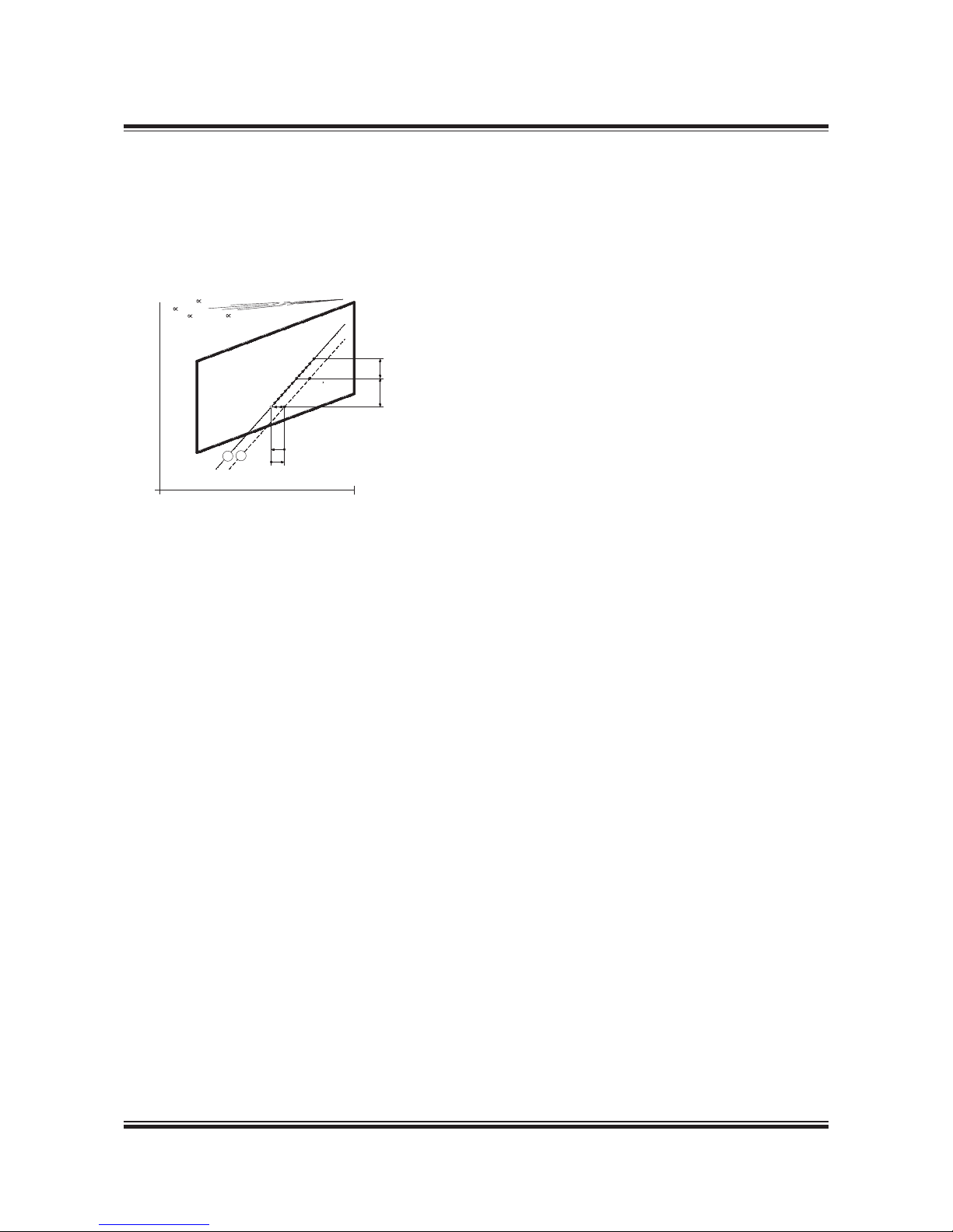
Fig. 2.01.03: Ship propulsion running points and engine
layout
Power, % af L
1
100%
= 0,15
= 0,20
= 0,25 = 0,30
L
3
100%
L
4
L
2
Engine margin
(SP=90% of MP)
Sea margin
(15% of PD)
Engine speed, % of L
1
L
1
MP
SP
PD
HR
LR
2 6
PD
Line 2 Propulsion curve, fouled hull and heavy weather
(heavy running), recommended for engine layout
Line 6 Propulsion curve, clean hull and calm weather (light
running), for propeller layout
MP Specified MCR for propulsion
SP Continuous service rating for propulsion
PD Propeller design point
HR Heavy running
LR Light running
Fouled hull
When the ship has sailed for some time, the hull
and propeller become fouled and the hull’s resistance will increase. Consequently, the ship’s
speed will be reduced unless the engine delivers
more power to the propeller, i.e. the propeller will
be further loaded and will be heavy running (HR).
As modern vessels with a relatively high service
speed are prepared with very smooth propeller
and hull surfaces, the gradual fouling after sea
trial will increase the hull’s resistance and make
the propeller heavier running.
Sea margin and heavy weather
If, at the same time the weather is bad, with head
winds, the ship’s resistance may increase compared to operating in calm weather conditions.
When determining the necessary engine power, it
is normal practice to add an extra power margin,
178 05 415.3
Page 33
MAN B&W 2.02
Page 1 of 2
MAN Diesel
198 38 78 2.6MAN B&W MC/MC-C, ME/ME-C/ME -B/GI engines
$ææ/PTIMUMæPROPELLERæDIAMETERS
0$ææ0ITCHDIAMETERæRATIO
3HAFTæPOWER
K7
RMIN
0ROPELLER
SPEED
0$
$
M
M
M
M
M
$
0$
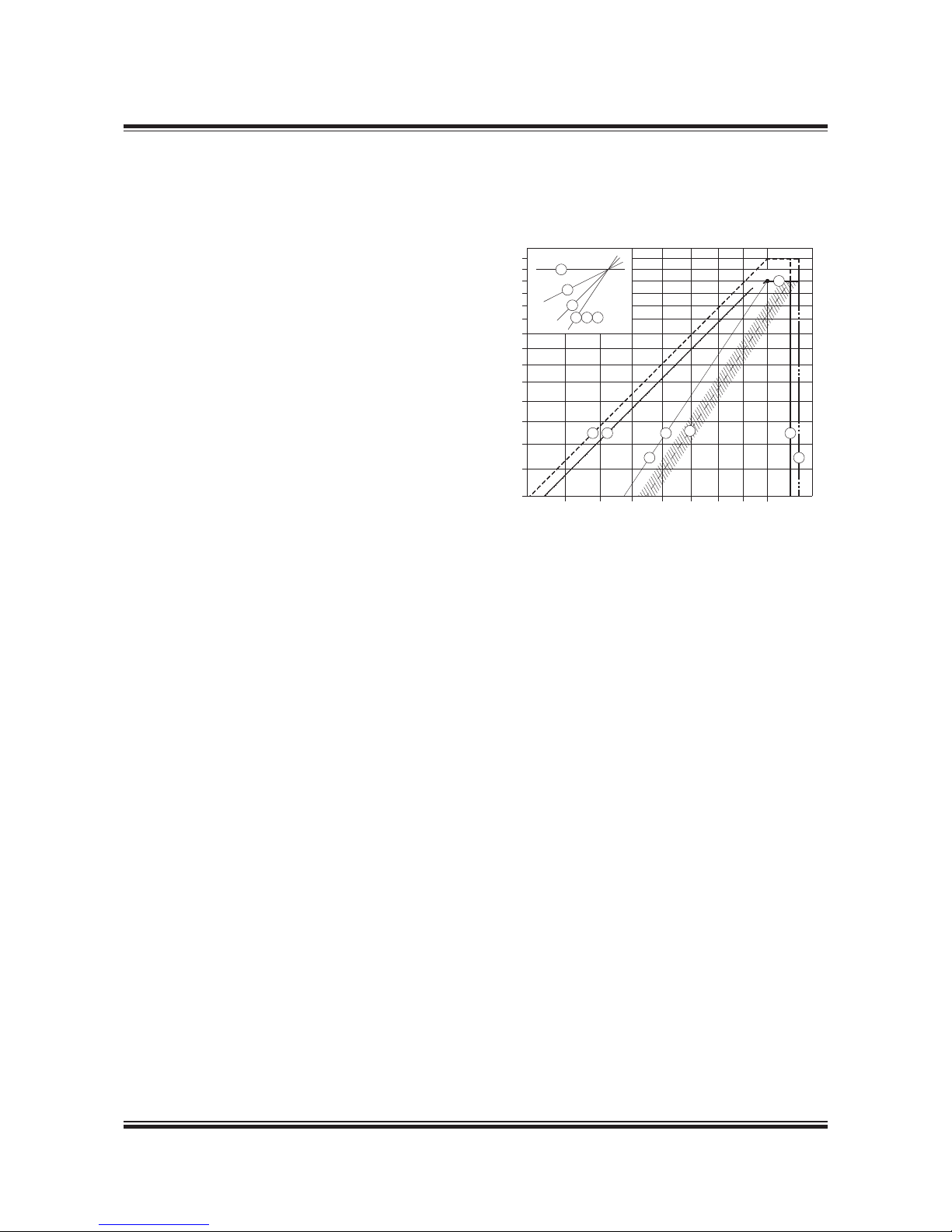
Fig. 2.02.01: Influence of diameter and pitch on propeller design
Propeller diameter and pitch, influence on the optimum propeller speed
In general, the larger the propeller diameter D,
the lower is the optimum propeller speed and the
kW required for a certain design draught and ship
speed, see curve D in the figure below.
The maximum possible propeller diameter depends on the given design draught of the ship,
and the clearance needed between the propeller
and the aft body hull and the keel.
The example shown in the figure is an 80,000 dwt
crude oil tanker with a design draught of 12.2 m
and a design speed of 14.5 knots.
When the optimum propeller diameter D is increased from 6.6 m to 7.2. m, the power demand
is reduced from about 9,290 kW to 8,820 kW, and
the optimum propeller speed is reduced from 120
r/min to 100 r/min, corresponding to the constant
ship speed coefficient
∝ = 0.28 (see definition of
∝ in Section 2.02, page 2).
Once an optimum propeller diameter of maximum
7.2 m has been chosen, the corresponding optimum pitch in this point is given for the design
speed of 14.5 knots, i.e. P/D = 0.70.
However, if the optimum propeller speed of 100
r/min does not suit the preferred / selected main
engine speed, a change of pitch away from optimum will only cause a relatively small extra power
demand, keeping the same maximum propeller
diameter:
going from 100 to 110 r/min (P/D = 0.62) requires
8,900 kW i.e. an extra power demand of 80 kW.
going from 100 to 91 r/min (P/D = 0.81) requires
8,900 kW i.e. an extra power demand of 80 kW.
In both cases the extra power demand is only
of 0.9%, and the corresponding ‘equal speed
curves’ are ∝ =+0.1 a nd ∝ =0.1, respectively, so
there is a certain interval of propeller speeds in
which the ‘power penalty’ is very limited.
178 47 032.0
Page 34
MAN B&W 2.02
Page 2 of 2
MAN Diesel
198 38 78 2.6MAN B&W MC/MC-C, ME/ME-C/ME -B/GI engines
Constant ship speed lines
The constant ship speed lines ∝, are shown at
the very top of Fig. 2.02.02. These lines indicate
the power required at various propeller speeds to
keep the same ship speed provided that the optimum propeller diameter with an optimum pitch
diameter ratio is used at any given speed, taking
into consideration the total propulsion efficiency.
Normally, the following relation between necessary power and propeller speed can be assumed:
P2 = P1 × (n2/n1)
∝
where:
P = Propulsion power
n = Propeller speed, and
∝= the constant ship speed coefficient.
For any combination of power and speed, each
point on lines parallel to the ship speed lines gives
the same ship speed.
When such a constant ship speed line is drawn
into the layout diagram through a specified propulsion MCR point ‘MP
1
’, selected in the layout
area and parallel to one of the
∝lines, another
specified propulsion MCR point ‘MP2’ upon this
line can be chosen to give the ship the same
speed for the new combination of engine power
and speed.
Fig. 2.02.02 shows an example of the required
power speed point MP1, through which a constant
ship speed curve ∝= 0.25 is drawn, obtaining
point MP2 with a lower engine power and a lower
engine speed but achieving the same ship speed.
Provided the optimum pitch/diameter ratio is used
for a given propeller diameter the following data
applies when changing the propeller diameter:
for general cargo, bulk carriers and tankers
∝= 0.25 0.30
and for reefers and container vessels
∝= 0.15 0.25
When changing the propeller speed by changing
the pitch diameter ratio, the ∝ constant will be dif-
ferent, see above.
Fig. 2.02.02: Layout diagram and constant ship speed lines
178 05 667.0
=0,15
=0,20
=0,25
=0,30
C
o
ns
ta
nt s
h
ip
s
p
e
e
d
lin
e
s
MP
2
MP
1
=0,25
1
2
3
4
m
ep
1
0
0
%
9
5
%
9
0
%
8
5
%
8
0
%
7
5
%
7
0
%
Nominal propeller curve
75% 80% 85% 90% 95% 100% 105%
Engine speed
Power
110%
100%
90%
80%
70%
60%
50%
40%
Page 35

MAN B&W 2.03
Page 1 of 1
MAN Diesel
198 82 77-0.7MAN B&W MC/MC-C, ME/ME-C/ME-B/-GI.2-TII engines
Power
Speed
L
4
L
2
L
1
L
3
Power
Speed
L
4
L
2
L
1
L
3
Power
Speed
L
4
L
2
L
1
L
3
L
4
L
2
L
1
L
3
Power
Speed
L
4
L
2
L
1
L
3
Power
Speed
L
4
L
2
L
1
L
3
Power
Speed
L
4
L
2
L
1
L
3
Power
Speed
L
4
L
2
L
1
L
3
Power
Speed
L
4
L
2
L
1
L
3
Speed
100 - 80% power and
100 - 85% speed range
valid for the types:
G80ME-C9.2-Basic
S70/65MC-C/ME-C8.2
S60MC-C/ME-C/ME-B8.3
L60MC-C/ME-C8.2
G/S50ME-B9.3
S50MC-C/ME-C8.2/ME-B8.3
S46MC-C/ME-B8.3
G45ME-B9.3
G/S40ME-B9.3, S40MC-C
S35MC-C/ME-B9.3
S30ME-B9.3
100 - 80% power and
100 - 87.5% speed range
valid for the types:
G95ME-C9.2
100 - 80% power and
100 - 90% speed range
valid for the types:
K80ME-C9.2
100 - 80% power and
100 - 85.7% speed range
valid for the types:
S90ME-C10.2
S90ME-C9.2
S80ME-C8.2
Fig. 2.03.01 Layout diagram sizes
Layout Diagram Sizes
178 62 22-5.3
See also Section 2.05 for actual project.
100 - 80% power and
100 - 79% speed range
valid for the types:
G70ME-C9.2
G60ME-C9.2
100 - 80% power and
100 - 84% speed range
valid for the types:
L70MC-C/ME-C8.2
100 - 80% power and
100 - 92% speed range
valid for the types:
S80ME-C9.2/4
S90ME-C8.2
100 - 80% power and
100 - 93% speed range
valid for the types:
K98ME/ME-C7.1
100 - 80% power and
100 - 81% speed range
valid for the types:
G80ME-C9.2-Extended
Page 36

MAN B&W 2.04
Page 1 of 9
MAN Diesel
198 69 93-5.3 MAN B&W MC/MC-C/ME/ME-C/ME-B/-GI-TII engines
Engine Layout and Load Diagram
Engine Layout Diagram
An engine’s layout diagram is limited by two constant mean effective pressure (mep) lines L1– L3
and L2– L4, and by two constant engine speed
lines L1– L2 and L3– L4. The L1 point refers to the
engine’s nominal maximum continuous rating, see
Fig. 2.04.01.
Within the layout area there is full freedom to select the engine’s specified SMCR point M which
suits the demand for propeller power and speed
for the ship.
On the horizontal axis the engine speed and on
the vertical axis the engine power are shown on
percentage scales. The scales are logarithmic
which means that, in this diagram, power function
curves like propeller curves (3rd power), constant
mean effective pressure curves (1st power) and
constant ship speed curves (0.15 to 0.30 power)
are straight lines.
Specified maximum continuous rating (M)
Based on the propulsion and engine running
points, as previously found, the layout diagram
of a relevant main engine may be drawnin. The
SMCR point (M) must be inside the limitation lines
of the layout diagram; if it is not, the propeller
speed will have to be changed or another main
engine type must be chosen. The selected SMCR
has an influence on the turbocharger and its
matching and the compression ratio.
For ME and ME-C/-GI engines, the timing of the
fuel injection and the exhaust valve activation are
electronically optimised over a wide operating
range of the engine.
For ME-B engines, only the fuel injection (and not
the exhaust valve activation) is electronically controlled over a wide operating range of the engine.
178 60 85-8.1
Fig. 2.04.01: Engine layout diagram
L
1
L
2
L
3
L
4
Speed
Power
M
S
1
For a standard high-load optimised engine,
the lowest specific fuel oil consumption for
the ME and ME-C engines is optained at 70%
and for MC/MC-C/ME-B engines at 80% of the
SMCR point (M).
For ME-C-GI engines operating on LNG, a further
SFOC reduction can be obtained.
Continuous service rating (S)
The continuous service rating is the power needed in service – including the specified sea margin
and heavy/light running factor of the propeller
– at which the engine is to operate, and point S
is identical to the service propulsion point (SP)
unless a main engine driven shaft generator is installed.
Page 37
MAN B&W 2.04
Page 2 of 9
MAN Diesel
198 69 93-5.3MAN B&W MC/MC-C/ME/ME-C/ME-B/-GI-TII engines
Engine shaft power, % of A
40
45
50
55
60
65
70
75
80
85
90
95
100
105
110
7
5
4
12
6
7
8
4
1
2
6
5
M
3
9
Engine speed, % of A
60
65
70
75
80
85 90 95 100 105 110
Definitions
The engine’s load diagram, see Fig. 2.04.02, defines the power and speed limits for continuous as
well as overload operation of an installed engine
having a specified MCR point M that confirms the
ship’s specification.
The service points of the installed engine incorporate the engine power required for ship propulsion
and shaft generator, if installed.
Operating curves and limits for continuous
operation
The continuous service range is limited by four
lines: 4, 5, 7 and 3 (9), see Fig. 2.04.02. The propeller curves, line 1, 2 and 6 in the load diagram
are also described below.
Line 1:
Propeller curve through specified MCR (M), engine layout curve.
Line 2:
Propeller curve, fouled hull and heavy weather
– heavy running.
Line 3 and line 9:
Line 3 represents the maximum acceptable speed
for continuous operation, i.e. 105% of M.
During trial conditions the maximum speed may
be extended to 107% of M, see line 9.
The above limits may in general be extended to
105% and during trial conditions to 107% of the
nominal L1 speed of the engine, provided the torsional vibration conditions permit.
The overspeed setpoint is 109% of the speed
in M, however, it may be moved to 109% of the
nominal speed in L
1
, provided that torsional vibra-
tion conditions permit.
Running at low load above 100% of the nominal L
1
speed of the engine is, however, to be avoided for
extended periods. Only plants with controllable
pitch propellers can reach this light running area.
Line 4:
Represents the limit at which an ample air supply
is available for combustion and imposes a limitation on the maximum combination of torque and
speed.
Regarding ‘i’ in the power function P = c x ni, see page 2.01.
M Specified MCR point
Line 1 Propeller curve through point M (i = 3)
(engine layout curve)
Line 2 Propeller curve, fouled hull and heavy weather
– heavy running (i = 3)
Line 3 Speed limit
Line 4 Torque/speed limit (i = 2)
Line 5 Mean effective pressure limit (i = 1)
Line 6 Propeller curve, clean hull and calm weather
– light running (i = 3), for propeller layout
Line 7 Power limit for continuous running (i = 0)
Line 8 Overload limit
Line 9 Speed limit at sea trial
178 05 427.6
Fig. 2.04.02: Standard engine load diagram
Engine Load Diagram
Page 38

MAN B&W 2.04
Page 3 of 9
MAN Diesel
198 69 93-5.3 MAN B&W MC/MC-C/ME/ME-C/ME-B/-GI-TII engines
Recommendation
Continuous operation without limitations is allowed only within the area limited by lines 4, 5,
7 and 3 of the load diagram, except on low load
operation for CP propeller plants mentioned in the
previous section.
The area between lines 4 and 1 is available for
operation in shallow waters, heavy weather and
during acceleration, i.e. for nonsteady operation
without any strict time limitation.
After some time in operation, the ship’s hull and
propeller will be fouled, resulting in heavier running of the propeller, i.e. the propeller curve will
move to the left from line 6 towards line 2, and
extra power is required for propulsion in order to
keep the ship’s speed.
In calm weather conditions, the extent of heavy
running of the propeller will indicate the need for
cleaning the hull and possibly polishing the propeller.
Once the specified MCR has been chosen, the
capacities of the auxiliary equipment will be
adapted to the specified MCR, and the turbocharger specification and the compression ratio
will be selected.
If the specified MCR is to be increased later on,
this may involve a change of the pump and cooler
capacities, change of the fuel valve nozzles, adjusting of the cylinder liner cooling, as well as
rematching of the turbocharger or even a change
to a larger size of turbocharger. In some cases it
can also require larger dimensions of the piping
systems.
It is therefore of utmost importance to consider,
already at the project stage, if the specification
should be prepared for a later power increase.
This is to be indicated in the Extent of Delivery.
Line 5:
Represents the maximum mean effective pressure level (mep), which can be accepted for continuous operation.
Line 6:
Propeller curve, clean hull and calm weather – light
running, used for propeller layout/design.
Line 7:
Represents the maximum power for continuous
operation.
Limits for overload operation
The overload service range is limited as follows:
Line 8:
Represents the overload operation limitations.
The area between lines 4, 5, 7 and the heavy
dashed line 8 is available for overload running for
limited periods only (1 hour per 12 hours).
Line 9:
Speed limit at sea trial.
Limits for low load running
As the fuel injection for ME engines is automatically controlled over the entire power range, the
engine is able to operate down to around 15-20%
of the nominal L
1
speed, whereas for MC/MC-C
engines it is around 20-25% (electronic governor).
Page 39

MAN B&W 2.04
Page 4 of 9
MAN Diesel
198 69 93-5.3MAN B&W MC/MC-C/ME/ME-C/ME-B/-GI-TII engines
Extended load diagram for ships operating in extreme heavy running conditions
When a ship with fixed pitch propeller is operating in normal sea service, it will in general be
operating in the hatched area around the design
propeller curve 6, as shown on the standard load
diagram in Fig. 2.04.02.
Sometimes, when operating in heavy weather, the
fixed pitch propeller performance will be more
heavy running, i.e. for equal power absorption of
the propeller, the propeller speed will be lower
and the propeller curve will move to the left.
As the low speed main engines are directly coupled to the propeller, the engine has to follow the
propeller performance, i.e. also in heavy running
propeller situations. For this type of operation,
there is normally enough margin in the load area
between line 6 and the normal torque/speed limitation line 4, see Fig. 2.04.02. To the left of line 4
in torquerich operation, the engine will lack air
from the turbocharger to the combustion process,
i.e. the heat load limits may be exceeded and
bearing loads might also become too high.
For some special ships and operating conditions,
it would be an advantage when occasionally
needed to be able to operate the propeller/main
engine as much as possible to the left of line 6,
but inside the torque/speed limit, line 4.
Such cases could be for:
• ships sailing in areas with very heavy weather
• ships operating in ice
• ships with two fixed pitch propellers/two main
engines, where one propeller/one engine is declutched for one or the other reason.
The increase of the operating speed range between line 6 and line 4 of the standard load diagram, see Fig. 2.04.02, may be carried out as
shown for the following engine Example with an
extended load diagram for speed derated engine
with increased light running.
Extended load diagram for speed derated engines with increased light running
The maximum speed limit (line 3) of the engines is
105% of the SMCR (Specified Maximum Continuous Rating) speed, as shown in Fig. 2.04.02.
However, for speed and, thereby, power derated
engines it is possible to extend the maximum
speed limit to 105% of the engine’s nominal MCR
speed, line 3’, but only provided that the torsional
vibration conditions permit this. Thus, the shafting, with regard to torsional vibrations, has to be
approved by the classification society in question,
based on the extended maximum speed limit.
When choosing an increased light running to be
used for the design of the propeller, the load diagram area may be extended from line 3 to line 3’,
as shown in Fig. 2.04.03, and the propeller/main
engine operating curve 6 may have a correspondingly increased heavy running margin before exceeding the torque/speed limit, line 4.
A corresponding slight reduction of the propeller efficiency may be the result, due to the higher
propeller design speed used.
Page 40
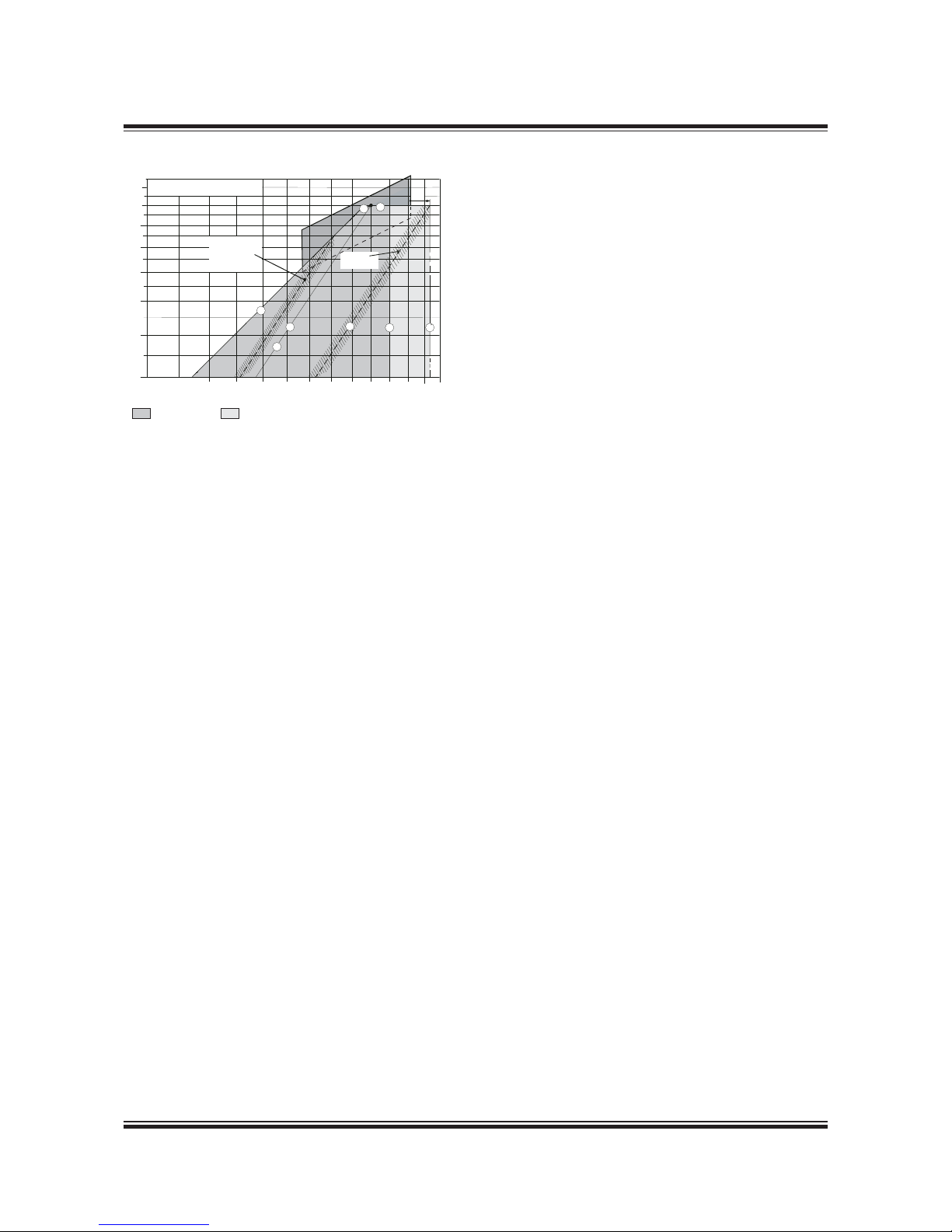
MAN B&W 2.04
Page 5 of 9
MAN Diesel
198 69 93-5.3 MAN B&W MC/MC-C/ME/ME-C/ME-B/-GI-TII engines
Examples of the use of the Load Diagram
In the following are some examples illustrating the
flexibility of the layout and load diagrams.
Example 1 shows how to place the load diagram
for an engine without shaft generator coupled to
a fixed pitch propeller.
Example 2 shows the same layout for an engine
with fixed pitch propeller (example 1), but with a
shaft generator.
Example 3 is a special case of example 2, where
the specified MCR is placed near the top of the
layout diagram.
In this case the shaft generator is cut off,
and the GenSets used when the engine runs
at specified MCR. This makes it possible to
choose a smaller engine with a lower power output, and with changed specified MCR.
Example 4 shows diagrams for an engine
coupled to a controllable pitch propeller, with
or without a shaft generator, constant speed or
combinator curve operation.
For a specific project, the layout diagram for actual project shown later in this chapter may be used
for construction of the actual load diagram.
80 100 1058555 90 9560
Engine speed, % A
M Specified engine MCR
Engine shaft power, % A
Heavy
running
operation
Normal
operation
50
70
80
90
100
40
110
60
110 115 120
L
1
M
L
2
5%
L
3
L
4
70 7565
Normal load
diagram area
Extended light
running area
2
1
5
7
6
3
3
4
Line 1: Propeller curve through SMCR point (M)
layout curve for engine
Line 2: Heavy propeller curve
fouled hull and heavy seas
Line 3: Speed limit
Line 3’: Extended speed limit, provided torsional vibration
conditions permit
Line 4: Torque/speed limit
Line 5: Mean effective pressure limit
Line 6: Increased light running propeller curve
clean hull and calm weather
layout curve for propeller
Line 7: Power limit for continuous running
178 60 79-9.1
Fig. 2.04.03: Extended load diagram for speed derated
engine with increased light running
Page 41
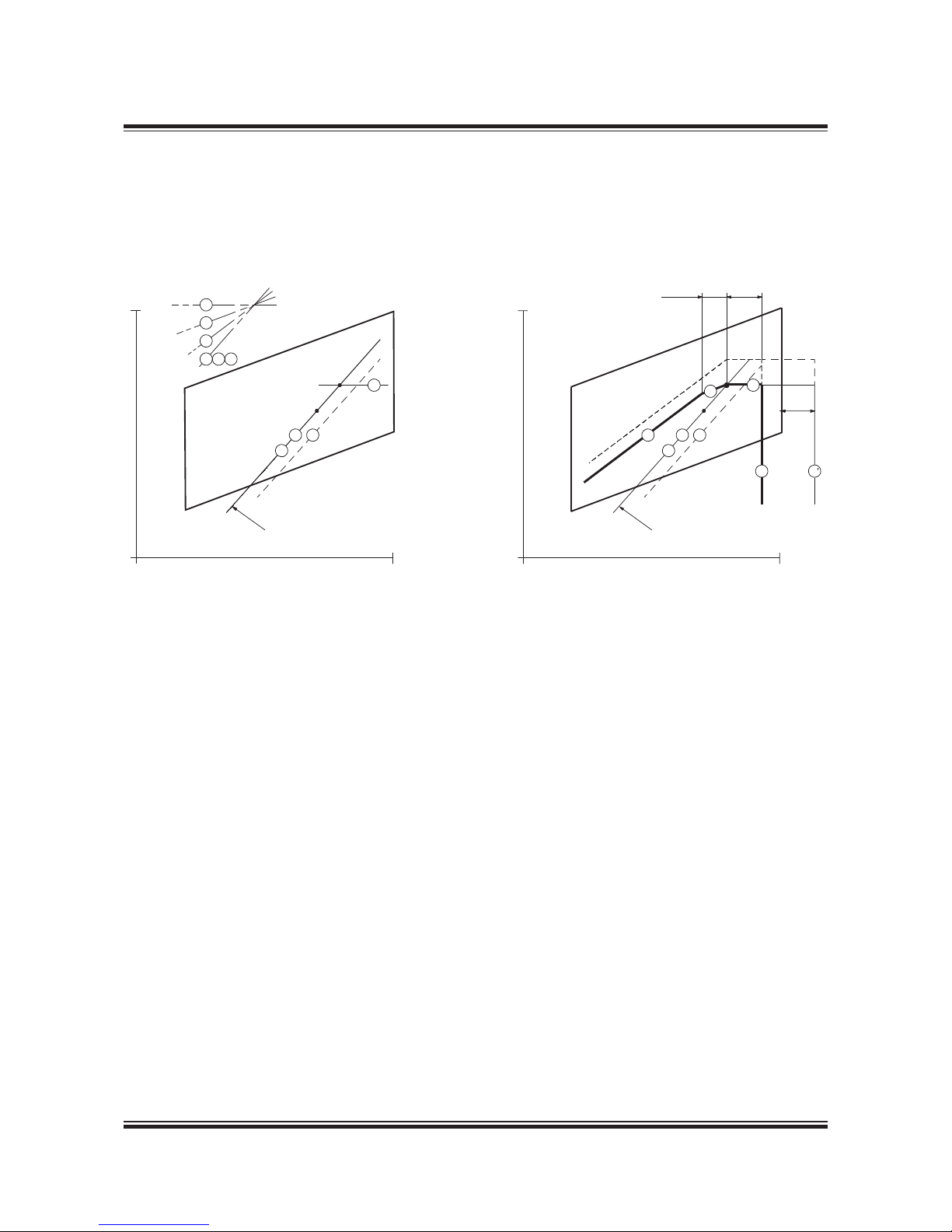
MAN B&W 2.04
Page 6 of 9
MAN Diesel
198 69 93-5.3MAN B&W MC/MC-C/ME/ME-C/ME-B/-GI-TII engines
Example 1: Normal running conditions.
Engine coupled to fixed pitch propeller (FPP) and without shaft generator
Propulsion and engine
service curve for fouled
hull and heavy weather
Engine speed, % of L
1
100%
Power, % of L
1
100%
7
5
4
1
26
1
2
6
7
M=MP
S=SP
Engine speed, % of L
1
100%
Power, % of L
1
100%
Propulsion and engine
service curve for fouled
hull and heavy weather
7
5
4
1
2
6
33
5%L
1
S
M
3.3%M
5%M
L
1
L
2
L
3
L
4
L
1
L
2
L
3
L
4
M Specified MCR of engine
S Continuous service rating of engine
MP Specified MCR for propulsion
SP Continuous service rating of propulsion
178 05 440.9
The specified MCR (M) and its propeller cur ve 1 will normally be selected on the engine service curve 2.
Once point M has been selected in the layout diagram, the load diagram can be drawn, as shown in the figure, and hence the actual
load limitation lines of the diesel engine may be found by using the inclinations from the construction lines and the %figures stated.
Layout diagram Load diagram
Fig. 2.04.04: Normal running conditions. Engine coupled to a fixed pitch propeller (FPP) and without a shaft generator
Page 42
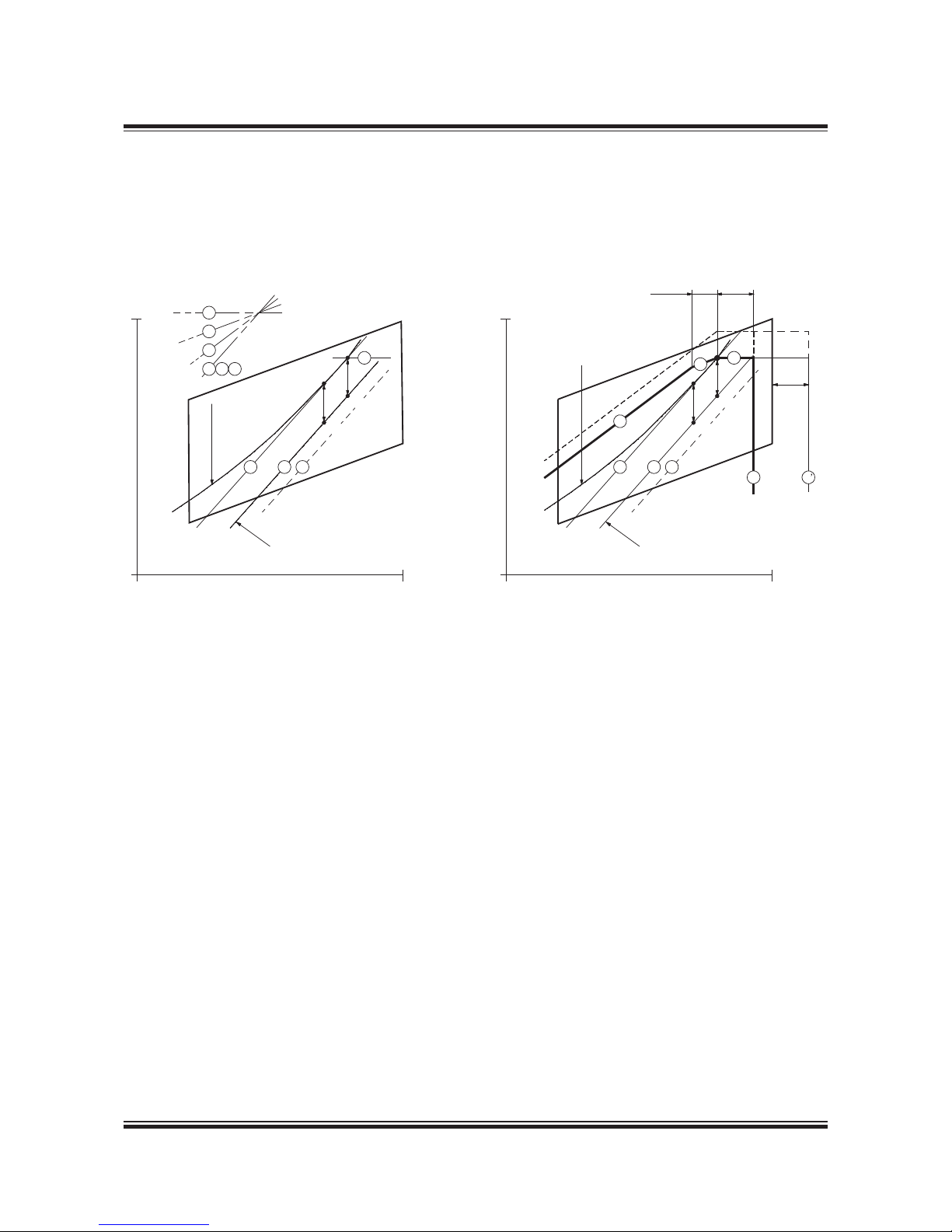
MAN B&W 2.04
Page 7 of 9
MAN Diesel
198 69 93-5.3 MAN B&W MC/MC-C/ME/ME-C/ME-B/-GI-TII engines
Example 2: Normal running conditions.
Engine coupled to fixed pitch propeller (FPP) and with shaft generator
M Specified MCR of engine
S Continuous service rating of engine
MP Specified MCR for propulsion
SP Continuous service rating of propulsion
SG Shaft generator power
178 05 488.9
In example 2 a shaft generator (SG) is installed, and therefore the service power of the engine also has to incorporate the extra shaf t
power required for the shaft generator’s electrical power production.
In the figure, the engine service curve shown for heavy running incorporates this extra power.
The specified MCR M will then be chosen and the load diagram can be drawn as shown in the figure.
Engine speed, % of L
1
100%
Power, % of L
1
100%
7
5
4
1
2
6
1
2
6
Propulsion curve for fouled
hull and heavy weather
Engine
service
curve
7
M
S
SP
SG
SG
MP
Engine speed, % of L
1
100%
Power, % of L
1
100%
Propulsion curve for fouled
hull and heavy weather
Engine service curve for
fouled hull and heavy
weather incl. shaft
generator
4
1
2
6
M
S
SP
MP
3
5
7
3.3%M 5%M
5%L
1
3
L
1
L
2
L
3
L
4
L
1
L
2
L
3
L
4
Layout diagram Load diagram
Fig. 2.04.06: Normal running conditions. Engine coupled to a fixed pitch propeller (FPP) and with a shaft generator
Page 43
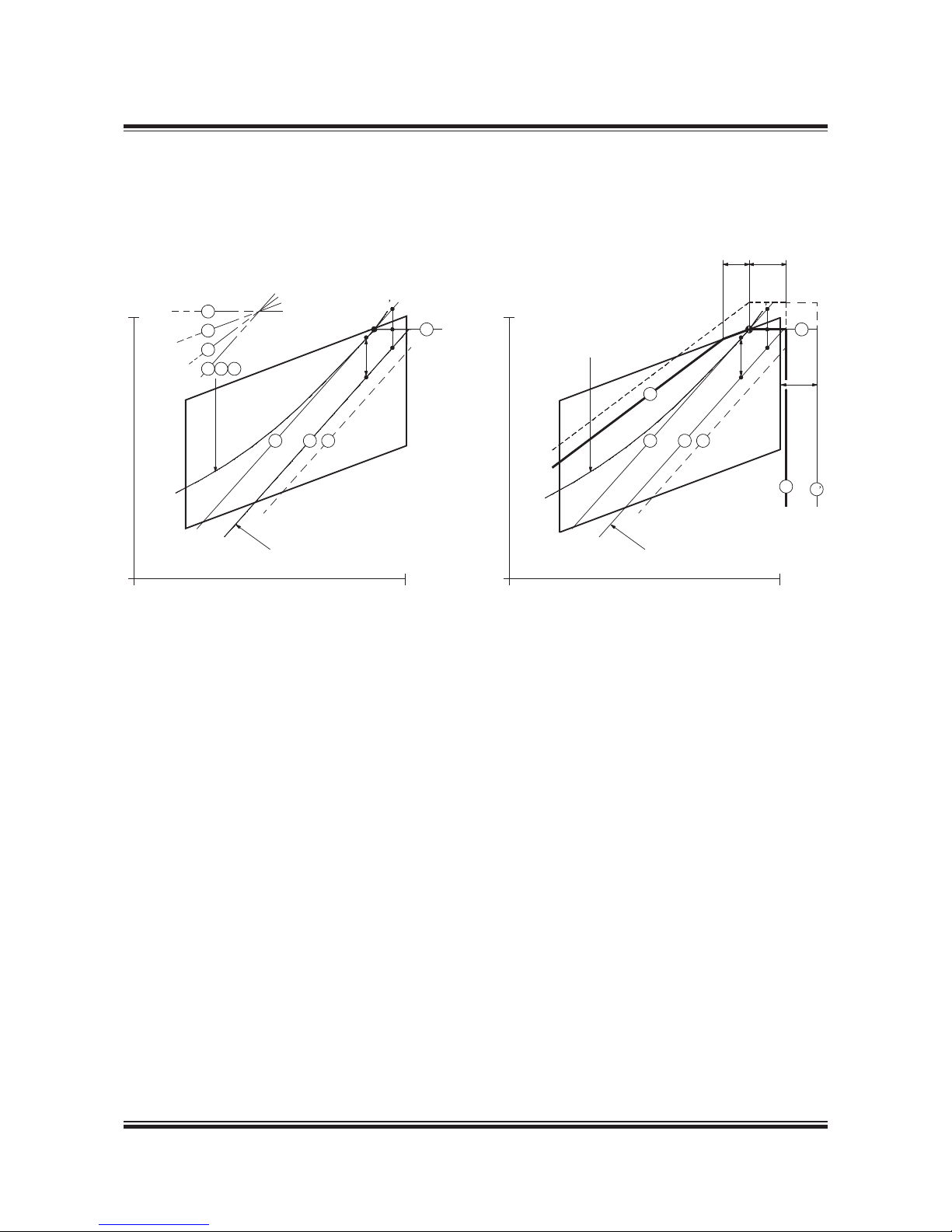
MAN B&W 2.04
Page 8 of 9
MAN Diesel
198 69 93-5.3MAN B&W MC/MC-C/ME/ME-C/ME-B/-GI-TII engines
Example 3: Special running conditions.
Engine coupled to fixed pitch propeller (FPP) and with shaft generator
M Specified MCR of engine
S Continuous service rating of engine
MP Specified MCR for propulsion
SP Continuous service rating of propulsion
SG Shaft generator
Point M of the load diagram is found:
Line 1 Propeller curve through point S
Point M Intersection between line 1 and line L1 – L
3
178 06 351.9
Also for this special case in example 3, a shaft generator is installed but, compared to example 2, this case has a specified MCR for
propulsion, MP, placed at the top of the layout diagram.
This involves that the intended specified MCR of the engine M’ will be placed outside the top of the layout diagram.
One solution could be to choose a larger diesel engine with an extra cylinder, but another and cheaper solution is to reduce the
electrical power production of the shaft generator when running in the upper propulsion power range.
In choosing the latter solution, the required specified MCR power can be reduced from point M’ to point M as shown. Therefore,
when running in the upper propulsion power range, a diesel generator has to take over all or part of the electrical power production.
However, such a situation will seldom occur, as ships are rather infrequently running in the upper propulsion power range.
Point M, having the highest possible power, is then found at the intersection of line L
1
– L3 with line 1 and the corresponding load
diagram is drawn.
Propulsion curve
for fouled hull
and heavy weather
Power, % of L
1
100%
Engine speed, % of L
1
100%
7
5
4
1
2
6
1
26
7
SP
SG
MP
S
M
M
Propulsion curve
for fouled hull
and heavy weather
Power, % of L
1
100%
Engine speed, % of L
1
100%
1
2
6
7
SP
SG
MP
S
M
5%L
1
3.3%M
5%M
M
Engine service curve for fouled
hull and heavy weather
incl. shaft generator
4
3
3
L
1
L
2
L
3
L
4
L
1
L
2
L
3
L
4
Layout diagram Load diagram
Fig. 2.04.07: Special running conditions. Engine coupled to a fixed pitch propeller (FPP) and with a shaft generator
Page 44
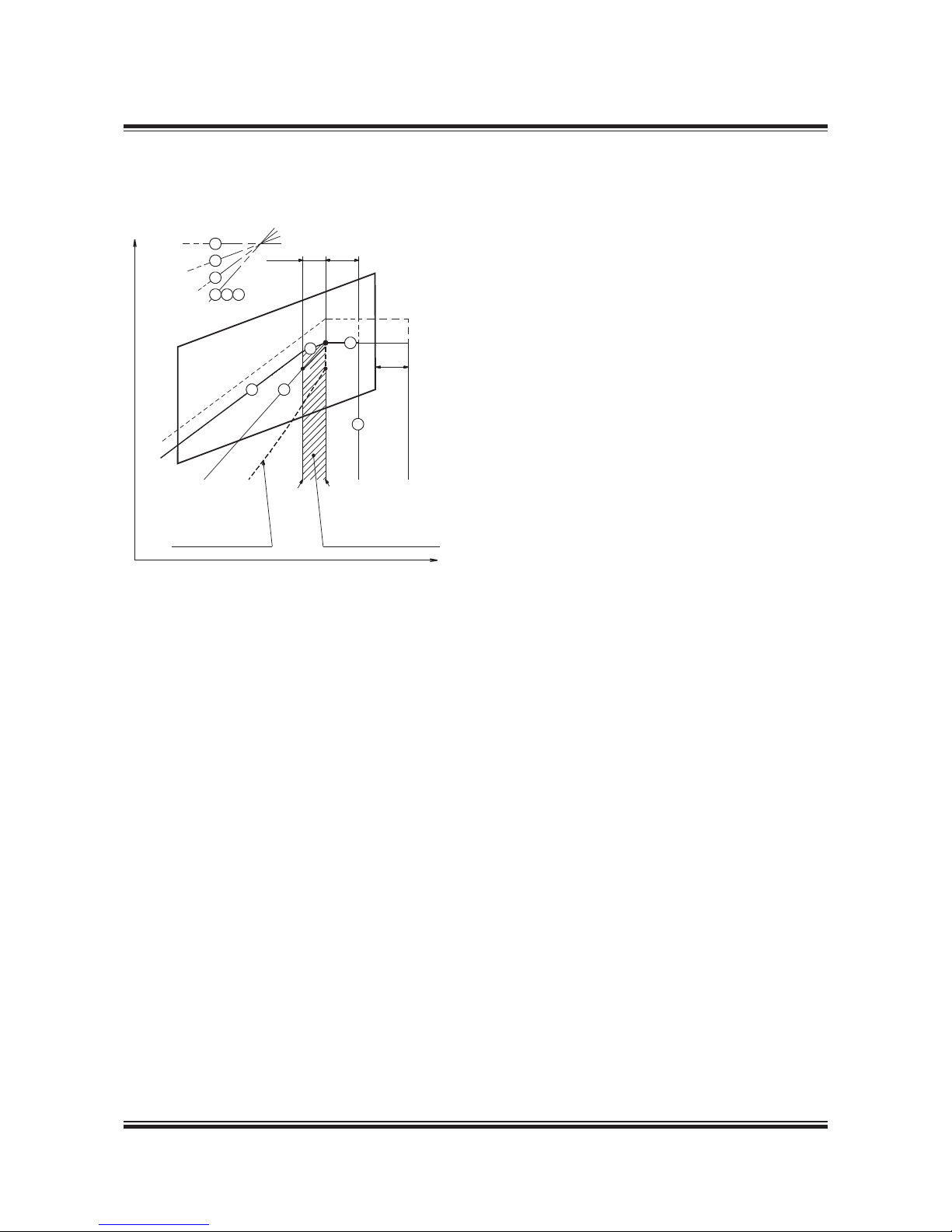
MAN B&W 2.04
Page 9 of 9
MAN Diesel
198 69 93-5.3 MAN B&W MC/MC-C/ME/ME-C/ME-B/-GI-TII engines
Example 4: Engine coupled to controllable pitch propeller (CPP) with or without shaft generator
Engine speed
Power
7
5
4
1
2
6
3.3%M
5%M
5%L
1
7
5
1
4
3
S
L
1
L
2
L
3
L
4
Min. speed
Max. speed
Combinator curve for
loaded ship and incl.
sea margin
Recommended range for
shaft generator operation
with constant speed
M
M Specified MCR of engine
S Continous service rating of engine
178 39 314.5
Fig. 2.04.08: Engine with Controllable Pitch Propeller
(CPP), with or without a shaft generator
Layout diagram without shaft generator
If a controllable pitch propeller (CPP) is applied,
the combinator curve (of the propeller) will normally be selected for loaded ship including sea
margin.
The combinator curve may for a given propeller
speed have a given propeller pitch, and this may
be heavy running in heavy weather like for a fixed
pitch propeller.
Therefore it is recommended to use a light running combinator curve (the dotted curve which
includes the sea power margin) as shown in the
figure to obtain an increased operation margin of
the diesel engine in heavy weather to the limit indicated by curves 4 and 5.
Layout diagram with shaft generator
The hatched area shows the recommended speed
range between 100% and 96.7% of the specified
MCR speed for an engine with shaft generator
running at constant speed.
The service point S can be located at any point
within the hatched area.
The procedure shown in examples 2 and 3 for
engines with FPP can also be applied here for engines with CPP running with a combinator curve.
Load diagram
Therefore, when the engine’s specified MCR point
(M) has been chosen including engine margin, sea
margin and the power for a shaft generator, if installed, point M may be used in the load diagram,
which can then be drawn.
The position of the combinator curve ensures the
maximum load range within the permitted speed
range for engine operation, and it still leaves a
reasonable margin to the limit indicated by curves
4 and 5.
Page 45
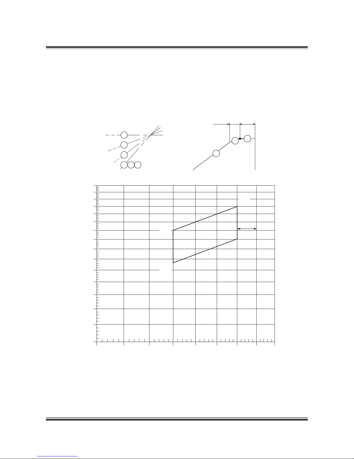
MAN B&W 2.05
Page 1 of 1
MAN Diesel
198 83 29 -8.1MAN B &W G80ME-C9 .2.68, S70 MC-C8.2, S 70ME-C8.2 /-GI,
S65MC-C8.2, S65ME-C8.2/-GI, S60MC-C8.2, S60ME-C8.2/-GI,
S60ME-B8.2, L60MC-C/ME-C8.2, S50MC-C8.2, G50ME-B9.3/.2,
S50ME-C8.2/-GI, S50ME-B9.3/.2, S50ME-B8.3/.2, S46MC-C8.2,
S46ME-B8.3/.2, S40MC-C8.2, G40ME-B9.3, S40ME-B9.3/.2,
S35MC-C8.2, S35ME-B9.3/.2-TII, S30ME-B9.3-TII
Fig. 2.05.01: Construction of layout diagram
70% 75% 80% 85% 90% 95% 100% 105% 110%
40%
50%
60%
70%
80%
90%
100%
110%
7
7
5
5
5
4
261
3.3%A
5%A
A
Engine speed, % of L
1
Power, % of L
1
5%L
1
L
1
L
2
L
3
L
4
Diagram for actual project
This figure contains a layout diagram that can
be used for constructing the load diagram for an
actual project, using the %figures stated and the
inclinations of the lines.
178 62 34-5.0
Page 46

MAN B&W 2.06
Page 1 of 1
MAN Diesel
198 86 55 -6.0
This section is not applicable
to -GI engines
Specific Fuel Oil Consumption, ME versus MC engines
Page 47
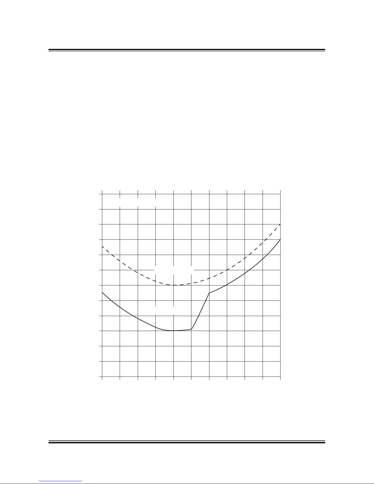
MAN B&W 2.07
Page 1 of 1
MAN Diesel
198 86 92- 6.0 MAN B &W S65ME-C8 .2/.5-GI-TII, S 60ME-C8. 2/.5-GI-TI I
SFOC for High Efficiency Turbochargers
Fig. 2.07.01: Example of part load SFOC curves for high efficiency turbochargers, valid for fuel oil and
gas fuel operation, respectively
178 64 54-9.0
For standard high load optimised ME/ME-C
engines operating on fuel oil the lowest SFOC at
part-load running may be obtained at 70% of the
specified MCR. However, for -GI engines operating on gas fuel the SFOC may be further reduced
on part load operation.
For more information visit: www.marine.man.eu →
’Two-Stroke’ → ’Turbocharger Selection’.
All -GI engines are as standard fitted with high
efficiency turbochargers, option: 4 59 104, and
can as standard only be high load optimised.
The high efficiency turbocharger is applied to the
engine in the basic design with the view to obtaining the lowest possible related Specific Fuel
Oil Consumption (SFOC) values, see example in
Fig. 2.07.01.
50% 60% 70% 80% 90%
0
1
-2
-3
-5
-7
-9
-1
+2
-4
-6
-8
-10
100%
Δ SFOC
g/kWh
Engine power, % of specified MCR
High efficiency turbocharger
Fuel oil operated
Gas fuel operated
Page 48

MAN B&W 2.08
Page 1 of 2
MAN Diesel
198 83 41-6.1MAN B &W TII .4 and .3 engi nes
MAN B&W T II .2 engines: 9 0-50ME-C /-GI,
70-35MC-C, 60-35ME-B/-GI
MAN B&W T II .1 engines: K98 ME/ME-C7
With
p
max
adjusted
Without
p
max
adjusted
Parameter
Condition
change
SFOC
change
SFOC
change
Scav. air coolant
temperature
per 10 °C rise + 0.60% + 0.41%
Blower inlet temperature
per 10 °C rise + 0.20% + 0.71%
Blower inlet
pressure
per 10 mbar
rise
0.02% 0.05%
Fuel oil lower
calorific value
rise 1%
(42,700 kJ/kg)
1.00% 1.00%
All engine design criteria, e.g. heat load, bearing
load and mechanical stresses on the construction are defined at 100% load independent of the
guarantee point selected. This means that turbocharger matching, engine adjustment and engine
load calibration must also be performed at 100%
independent of guarantee point. At 100% load,
the SFOC tolerance is 5%.
When choosing an SFOC guarantee below 100%,
the tolerances, which were previously compensated for by the matching, adjustment and calibration
at 100%, will affect engine running at the lower
SFOC guarantee load point. This includes tolerances on measurement equipment, engine process control and turbocharger performance.
Consequently, SFOC guarantee tolerances are:
• 100% – 85%: 5% tolerance
• 84% – 65%: 6% tolerance
• 64% – 50%: 7% tolerance
Please note that the SFOC guarantee can only be
given in one (1) load point.
Recommended cooling water temperature
during normal operation
In general, it is recommended to operate the main
engine with the lowest possible cooling water
temperature to the air coolers, as this will reduce
the fuel consumption of the engine, i.e. the engine
performance will be improved.
However, shipyards often specify a constant
(maximum) central cooling water temperature of
36 °C, not only for tropical ambient temperature
conditions, but also for lower ambient temperature
conditions. The purpose is probably to reduce the
electric power consumption of the cooling water
pumps and/or to reduce water condensation in
the air coolers.
Thus, when operating with 36 °C cooling water
instead of for example 10 °C (to the air coolers),
the specific fuel oil consumption will increase by
approx. 2 g/kWh.
SFOC at reference conditions
The SFOC is given in g/kWh based on
the reference ambient conditions stated in
ISO 3046-1:2002(E) and ISO 15550:2002(E):
• 1,000 mbar ambient air pressure
• 25 °C ambient air temperature
• 25 °C scavenge air coolant temperature
and is related to a fuel oil with a lower calorific
value of 42,700 kJ/kg (~10,200 kcal/kg).
Any discrepancies between g/kWh and g/BHPh
are due to the rounding of numbers for the latter.
For lower calorific values and for ambient conditions that are different from the ISO reference
conditions, the SFOC will be adjusted according
to the conversion factors in the table below.
With for instance 1 °C increase of the scavenge
air coolant temperature, a corresponding 1 °C increase of the scavenge air temperature will occur
and involves an SFOC increase of 0.06% if p
max
is
adjusted to the same value.
SFOC guarantee
The Energy Efficiency Design Index (EEDI) has
increased the focus on part- load SFOC. We
therefore offer the option of selecting the SFOC
guarantee at a load point in the range between
50% and 100%, EoD: 4 02 002.
SFOC reference conditions and guarantee
Page 49

MAN B&W 2.08
Page 2 of 2
MAN Diesel
MAN B&W M E-GI TII .2 engi nes 198 86 34 -1.0
Examples of Graphic Calculation of related SFOC for -GI engines
The following diagrams a (a1, a2 and a3), b (b1
and b2) and c (c1 and c2), valid for fixed pitch
propeller (b) and constant speed (c), respectively,
show the reduction of related SFOC in g/kWh,
relative to the SFOC of fuel oil operated engine for
the nominal MCR L1 rating.
Mep influence
The solid mep lines in b1 and c1 show the SFOC
reduction, and are valid at 100%, 70% and 50%
of SMCR point (M), and refer to derated engines
operation on fuel oil.
Point M is drawn into the abovementioned Diagrams b1 or c1. A straight line along the constant
mep curves (parallel to L
1L3
) is drawn through
point M. The intersections of this line and the
curves indicate the reduction in specific fuel oil
consumption at 100, 70 and 50% of the SMCR
point, related to the SFOC stated for the nominal
MCR L1 rating, when operating on fuel oil.
Rpm influence
The straight vertical lines in b2 and c2 along the
engine speed (rpm) lines show the extra SFOC reductions, and are valid at 100%/90%/80%, 75%,
65% and 50%/35% of SMCR point (M), and refer
to -GI engines operating on LNG.
Point M is already drawn into the above mentioned diagram b2 or c2. A straight vertical line
along the constant rpm curves (parallel to L1-L2
is drawn through point M. The intersections of
this line and the curves indicate the extra SFOC
reduction at 100%/90%/80%, 75%, 65% and
50%/35% of SMCR, for -GI engines operating on
LNG, compared to the SFOC valid for engine operating on fuel oil.
An example of the calculated SFOC curves
are shown in Diagram a (a1, a2 and a3), and is
valid for an engine with fixed pitch propeller, see
Fig. 2.10.01.
Page 50

MAN B&W 2.10
Page 1 of 2
MAN Diesel
MAN B&W S65ME-C8.2/-GI-TII 198 84 18-5 .0
Valid for standard high-load optimised engine
Data at nominel MCR (L
1
): 6S65ME-C8.2/-GI
Power 100% 17,220 kW
Speed 100% 95 r/min
Nominal SFOC:
• High efficiency turbocharger 169 g/kWh
Example of specified MCR = M
Power 15,498 kW (90% L1)
Speed 90.3 r/min (95% L
1
)
Turbocharger type High efficiency
SFOC found in M 167.4 g/kWh
The SMCR point M used in the above example for the
SFOC calculations:
M = 90% L
1
power and 95% L1 speed
SFOC calculations, example
Page 51
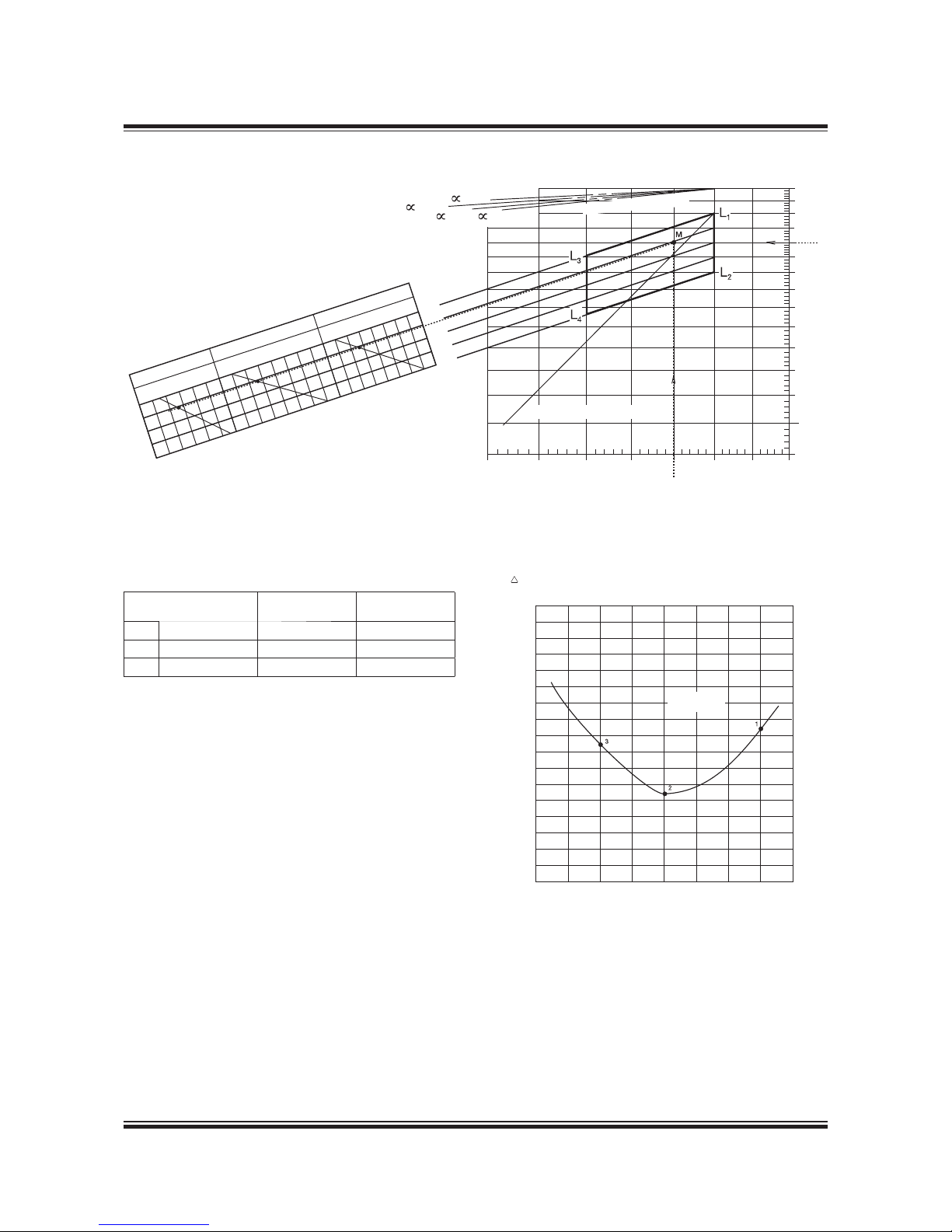
MAN B&W 2.10
Page 2 of 2
MAN Diesel
MAN B&W S65ME-C8.2/-GI-TII 198 84 18-5 .0
Fig. 2.10.01: Example of SFOC for derated 6S65ME-C8.2/-GI with fixed pitch propeller and high efficiency
turbocharger
40% 50% 60% 70% 80% 90% 100% 110%
Nominal SFOC
Diagram a
Part Load SFOC curve
30%
% of SMCR
SFOC
g/kWh
+1
+2
+3
+4
+5
+6
0
1
2
3
4
5
6
7
8
9
10
11
g/kWh
SFOC
165
160
170
175
169
50% SMCR
70% SMCR
100% SMCR
1 2 3 4 5
4 5 6 7 8 9 10
0 1 2 3 4 5 6
mep
100%
95%
85%
80%
90%
Constant ship speed lines
105%
40%
50%
60%
70%
80%
90%
100%
Power, % of L
1
Speed, % of L
1
75% 80% 85% 90% 95% 100%
Nominal propeller curve
=0.15
=0.25
=0.20
=0.30
Diagram b
Reduction of SFOC in g /kWh relative to the nominal in L
1
90%
95%
178 63 09-0.0
178 63 23-2.0
The reductions, see diagram b, in g/kWh compared to
SFOC in L
1
:
Part load points
SFOC
g/kWh
SFOC
g/kWh
1 100% M -1.6 167.4
2 70% M -5.6 163.4
3 50% M -2.6 166.4
Page 52
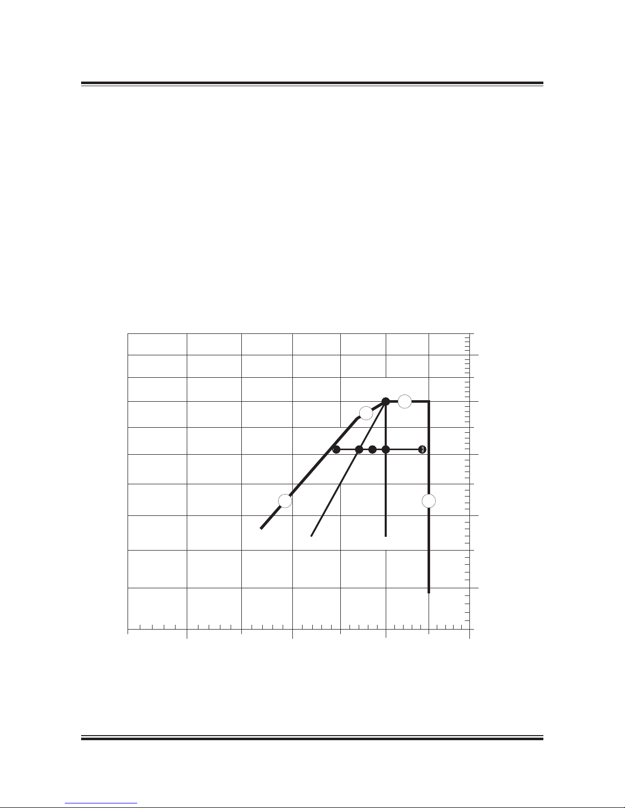
MAN B&W 2.11
Page 1 of 1
MAN Diesel
MAN B&W MC/MC-C/ME/ME-C/ME-B/-GI engines 198 38 43-4.5
Once the specified MCR (M) of the engine has
been chosen, the specific fuel oil consumption at
an arbitrary point S1, S2 or S3 can be estimated
based on the SFOC at point ‘1’ and ‘2’.
These SFOC values can be calculated by using
the graphs for the relevant engine type for the
propeller curve I and for the constant speed curve
II, giving the SFOC at points 1 and 2, respectively.
Next the SFOC for point S1 can be calculated as
an interpolation between the SFOC in points ‘1’
and ‘2’, and for point S3 as an extrapolation.
The SFOC curve through points S2, on the left
of point 1, is symmetrical about point 1, i.e. at
speeds lower than that of point 1, the SFOC will
also increase.
The abovementioned method provides only an
approximate value. A more precise indication of
the expected SFOC at any load can be calculated
by using our computer program. This is a service
which is available to our customers on request.
Power, % of
M
110%
100%
90%
80%
70%
80% 90% 100% 110%
Speed, % o f M
M
5
7
2
1
S
2
S
1
S
3
4
3
I
II
Fig. 2.11.01: SFOC at an arbitrary load
198 95 962.2
Fuel Consumption at an Arbitrary Load
Page 53

MAN B&W
MAN Diesel
Turbocharger Selection &
Exhaust Gas By-pass
3
Page 54

Page 55

MAN B&W 3.01
Page 1 of 1
MAN Diesel
198 87 28 -8.0MA N B&W S65MC- C8.2 /ME-C8.2. /-GI-TII
Updated turbocharger data based on the latest
information from the turbocharger makers are
available from the Turbocharger Selection program on www.marine.man.eu → ’Two-Stroke’ →
’Turbocharger Selection’.
The data specified in the printed edition are valid
at the time of publishing.
The MC/ME engines are designed for the application of either MAN, ABB or Mitsubishi (MHI) turbochargers.
The turbocharger choice is made with a view to
obtaining the lowest possible Specific Fuel Oil
Consumption (SFOC) values at the nominal MCR
by applying high efficiency turbochargers.
The engines are, as standard, equipped with as
few turbochargers as possible, see Table 3.01.01.
One more turbocharger can be applied, than the
number stated in the tables, if this is desirable due
to space requirements, or for other reasons. Additional costs are to be expected.
However, we recommend the ‘Turbocharger Selection’ program on the Internet, which can be
used to identify a list of applicable turbochargers
for a specific engine layout.
For information about turbocharger arrangement
and cleaning systems, see Section 15.01.
Table 3.01.01: High efficiency turbochargers
High ef ficiency turbochargers for the S65MC-C8.2/ME-C8. 2/-GI-TII engines L1 output at 95 rpm
Cyl. MAN (TCA) ABB (A-L) MHI (MET)
5 1 x TCA77-21 1 x A275-L 1 x MET71MB
6 1 x TCA77-26 1 x A180-L37 1 x MET83MB
7 1 x TCA88-21 1 x A280-L 1 x MET83MB
8 1 x TCA88-21 1 x A285-L 1 x MET66MB
Turbocharger Selection
Page 56
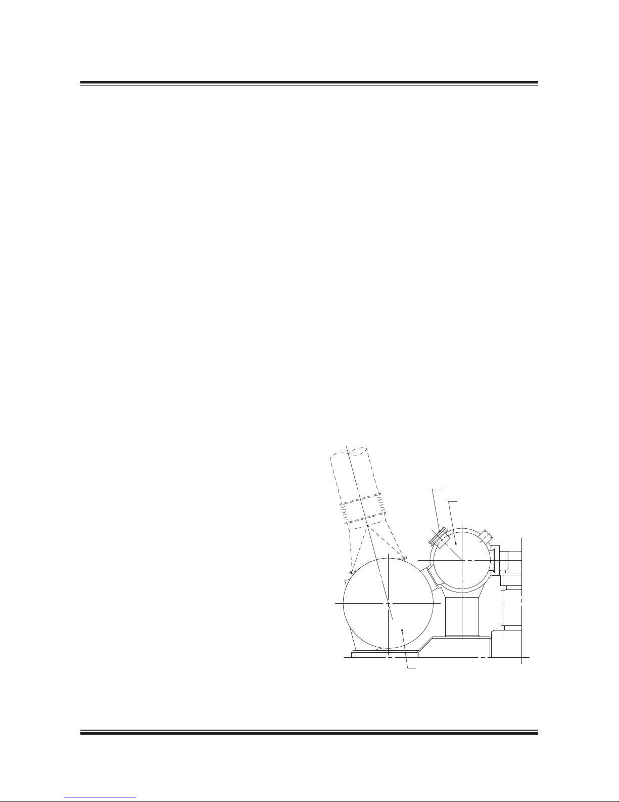
MAN B&W 3.02
Page 1 of 1
MAN Diesel
198 45 93 4.6MA N B&W 80-26M C/MC-C/ME /ME-C/ME- B/-GI engines
plied, the turbocharger size and specification has
to be determined by other means than stated in
this Chapter.
Emergency Running Condition
Exhaust gas receiver with total bypass flange
and blank counterflange
Option: 4 60 119
Bypass of the total amount of exhaust gas round
the turbocharger is only used for emergency running in the event of turbocharger failure on engines, see Fig. 3.02.01.
This enables the engine to run at a higher load
with only one turbocharger under emergency
conditions. The engine’s exhaust gas receiver will
in this case be fitted with a bypass flange of approximately the same diameter as the inlet pipe
to the turbocharger. The emergency pipe is yard’s
supply.
Extreme ambient conditions
As mentioned in Chapter 1, the engine power
figures are valid for tropical conditions at sea
level: 45 °C air at 1,000 mbar and 32 °C seawater,
whereas the reference fuel consumption is given
at ISO conditions: 25 °C air at 1,000 mbar and
25 °C charge air coolant temperature.
Marine diesel engines are, however, exposed to
greatly varying climatic temperatures winter and
summer in arctic as well as tropical areas. These
variations cause changes of the scavenge air
pressure, the maximum combustion pressure, the
exhaust gas amount and temperatures as well as
the specific fuel oil consumption.
For further information about the possible countermeasures, please refer to our publication titled:
Influence of Ambient Temperature Conditions
The publication is available at
www.marine.man.eu → ’Two-Stroke’ → ’Technical
Papers’
Arctic running condition
For air inlet temperatures below 10 °C the precautions to be taken depend very much on the
operating profile of the vessel. The following alternative is one of the possible countermeasures.
The selection of countermeasures, however, must
be evaluated in each individual case.
Exhaust gas receiver with variable bypass
Option: 4 60 118
Compensation for low ambient temperature can
be obtained by using exhaust gas bypass system.
This arrangement ensures that only part of the
exhaust gas goes via the turbine of the turbocharger, thus supplying less energy to the compressor which, in turn, reduces the air supply to
the engine.
Please note that if an exhaust gas bypass is ap-
Climate Conditions and Exhaust Gas Bypass
Fig. 3.02.01: Total bypass of exhaust for emergency running
178 06 721.2
Bypass flange
Exhaust receiver
Turbocharger
Centre of cylinder
Page 57

MAN B&W 3.03
Page 1 of 1
MAN Diesel
MAN B&W M E/MEC/M E-B/-GI TII engin es 198 84 47-2. 2
IMO Tier II NOx emission limits
All ME, ME-B and ME-C/-GI engines are, as
standard, fulfilling the IMO Tier II NOx emission
requirements, a speed dependent NOx limit measured according to ISO 8178 Test Cycles E2/E3 for
Heavy Duty Diesel Engines.
The E2/E3 test cycles are referred to in the Extent
of Delivery as EoD: 4 06 200 Economy mode with
the options: 4 06 201 Engine test cycle E3 or 4 06
202 Engine test cycle E2.
NOx reduction methods for IMO Tier III
As adopted by IMO for future enforcement, the
engine must fulfil the more restrictive IMO Tier III
NOx requirements when sailing in a NOx Emission
Control Area (NOx ECA).
The Tier III NOx requirements can be met by Exhaust Gas Recirculation (EGR), a method which
directly affects the combustion process by lowering the generation of NOx.
Alternatively, the required NOx level could be met
by installing Selective Catalytic Reaction (SCR),
an after treatment system that reduces the emission of NOx already generated in the combustion
process.
Details of MAN Diesel & Turbo’s NOx reduction
methods for IMO Tier III can be found in our publication:
Emission Project Guide
The publication is available at www.marine.man.
eu → ’Two-Stroke’ → ’Project Guides’ → ’Other
Guides’.
Emission Control
Page 58

Page 59

MAN B&W
MAN Diesel
Electricity Production
4
Page 60

Page 61

MAN B&W 4.01
Page 1 of 6
MAN Diesel
198 41 55- 0.5MAN B&W 98-50 MC/MC-C/ME/ME-C/ME-B/-GI engines
• PTO/GCR
(Power Take Off/Gear Constant Ratio):
Generator coupled to a constant ratio stepup
gear, used only for engines running at constant
speed.
The DMG/CFE (Direct Mounted Generator/Con-
stant Frequency Electrical) and the SMG/CFE
(Shaft Mounted Generator/Constant Frequency
Electrical) are special designs within the PTO/CFE
group in which the generator is coupled directly
to the main engine crankshaft or the intermediate
propeller shaft, respectively, without a gear. The
electrical output of the generator is controlled by
electrical frequency control.
Within each PTO system, several designs are
available, depending on the positioning of the
gear:
• BW I:
Gear with a vertical generator mounted onto the
fore end of the diesel engine, without any connections to the ship structure.
• BW II:
A freestanding gear mounted on the tank top
and connected to the fore end of the diesel engine, with a vertical or horizontal generator.
• BW III:
A crankshaft gear mounted onto the fore end of
the diesel engine, with a sidemounted generator without any connections to the ship structure.
• BW IV:
A freestanding stepup gear connected to the
intermediate propeller shaft, with a horizontal
generator.
The most popular of the gear based alternatives
are the BW III/RCF type for plants with a fixed
pitch propeller (FPP). The BW III/RCF requires no
separate seating in the ship and only little attention from the shipyard with respect to alignment.
Introduction
Next to power for propulsion, electricity production is the largest fuel consumer on board. The
electricity is produced by using one or more of the
following types of machinery, either running alone
or in parrallel:
• Auxiliary diesel generating sets
• Main engine driven generators
• Exhaust gas- or steam driven turbo generator
utilising exhaust gas waste heat (Thermo Efficiency System)
• Emergency diesel generating sets.
The machinery installed should be selected on the
basis of an economic evaluation of first cost, operating costs, and the demand for man-hours for
maintenance.
In the following, technical information is given regarding main engine driven generators (PTO), different configurations with exhaust gas and steam
driven turbo generators, and the auxiliary diesel
generating sets produced by MAN Diesel & Turbo.
Power Take Off
With a generator coupled to a Power Take Off
(PTO) from the main engine, electrical power can
be produced based on the main engine’s low
SFOC/SGC. Several standardised PTO systems
are available, see Fig. 4.01.01 and the designations in Fig. 4.01.02:
• PTO/RCF
(Power Take Off/Renk Constant Frequency):
Generator giving constant frequency, based on
mechanicalhydraulical speed control.
• PTO/CFE
(Power Take Off/Constant Frequency Electrical):
Generator giving constant frequency, based on
electrical frequency control.
Electricity Production
Page 62
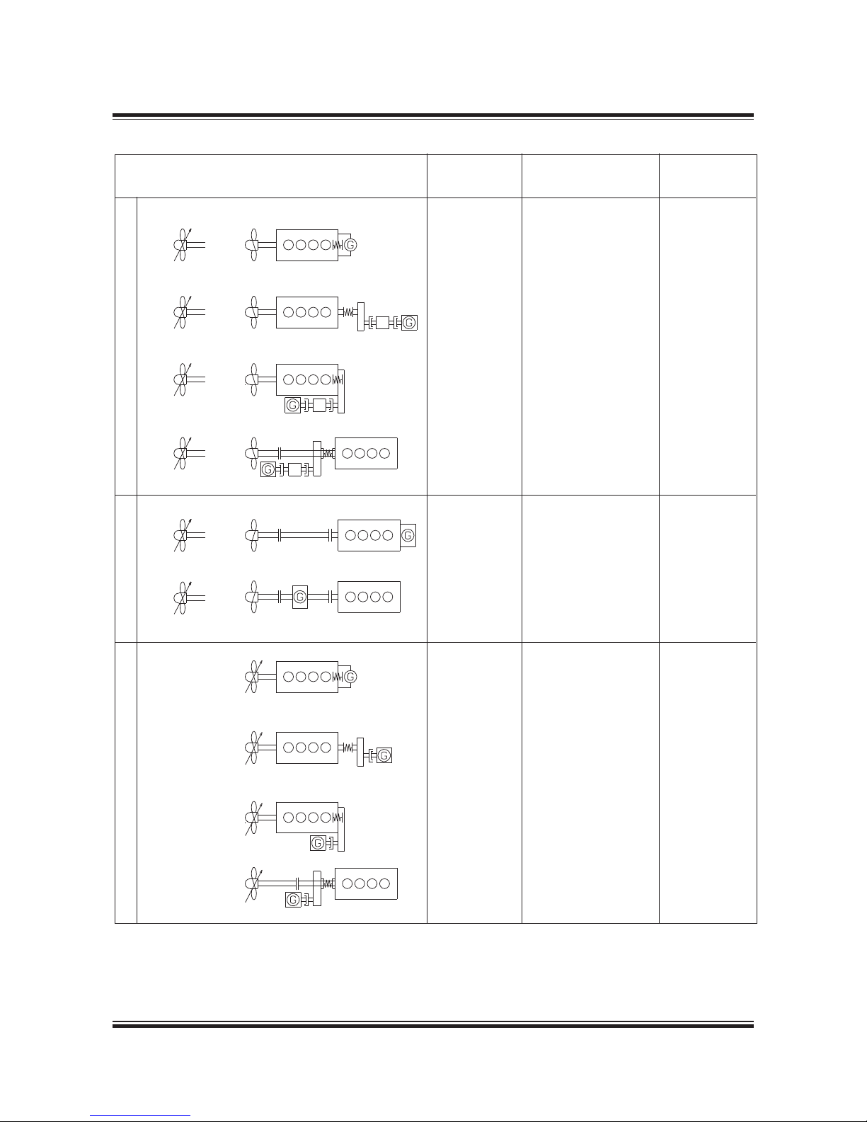
MAN B&W 4.01
Page 2 of 6
MAN Diesel
198 41 55- 0.5MAN B&W 98-50 MC/MC-C/ME/ME-C/ME-B/-GI engines
Total
Alternative types and layouts of shaft generators Design Seating efficiency (%)
1a 1b BW I/RCF On engine 8891
(vertical generator)
2a 2b BW II/RCF On tank top 8891
3a 3b BW III/RCF On engine 8891
4a 4b BW IV/RCF On tank top 8891
5a 5b DMG/CFE On engine 8488
6a 6b SMG/CFE On tank top 8991
7 BW I/GCR On engine 92
(vertical generator)
8 BW II/GCR On tank top 92
9 BW III/GCR On engine 92
10 BW IV/GCR On tank top 92
PTO/RCFPTO/CFEPTO/GCR
Fig. 4.01.01: Types of PTO
178 6 3 68-7. 0
Page 63

MAN B&W 4.01
Page 3 of 6
MAN Diesel
198 53 85 -5.5MAN B&W G70ME-C9, S/L70ME-C/-GI,
S65ME-C8/-GI, S60ME-C/ME-B/-GI,
L60ME-C, S50ME-C/ME-B, G50ME-B9
Power take off:
BW III S70MEC8-GI/RCF 70060
50: 50 Hz
60: 60 Hz
kW on generator terminals
RCF: Renk constant frequency unit
CFE: Electrically frequency controlled unit
GCR: Stepup gear with constant ratio
Mark version
Engine type on which it is applied
Layout of PTO: See Fig. 4.01.01
Make: MAN Diesel & Turbo
Fig. 4.01.02: Example of designation of PTO
178 39 556.0
For further information, please refer to our publication titled:
Shaft Generators for MC and ME engines
The publication is available at www.marine.man.
eu → ’Two-Stroke’ → ’Technical Papers’.
Designation of PTO
Page 64
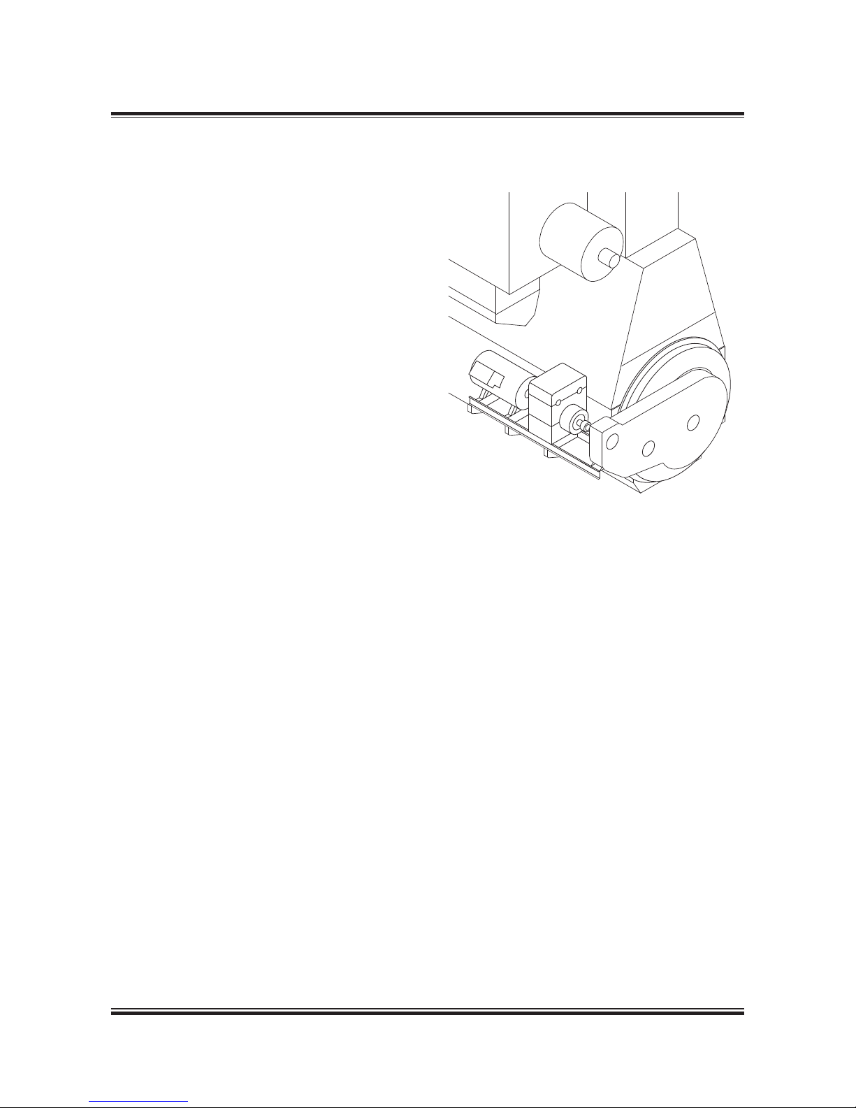
MAN B&W 4.01
Page 4 of 6
MAN Diesel
198 43 00 0.3M AN B&W 98-50 T II engines
PTO/RCF
Side mounted generator, BW III/RCF
(Fig. 4.01.01, Alternative 3)
The PTO/RCF generator systems have been developed in close cooperation with the German
gear manufacturer RENK. A complete package
solution is offered, comprising a flexible coupling,
a stepup gear, an epicyclic, variableratio gear
with builtin clutch, hydraulic pump and motor,
and a standard generator, see Fig. 4.01.04.
For marine engines with controllable pitch propellers running at constant engine speed, the hydraulic system can normally be omitted. For constant
speed engines a PTO/GCR design is normally
used.
Fig. 4.01.04 shows the principles of the PTO/
RCF arrangement. As can be seen, a stepup
gear box (called crankshaft gear) with three gear
wheels is bolted directly to front- and part side
engine crankcase structure. The bearings of the
three gear wheels are mounted in the gear box so
that the weight of the wheels is not carried by the
crankshaft. Between the crankcase and the gear
drive, space is available for tuning wheel, counterweights, axial vibration damper, etc.
The first gear wheel is connected to the crankshaft via a special flexible coupling, made in one
piece with a tooth coupling driving the crankshaft
gear, thus isolating the gear drive against torsional
and axial vibrations.
By means of a simple arrangement, the shaft in
the crankshaft gear carrying the first gear wheel
and the female part of the toothed coupling can
be moved forward, thus disconnecting the two
parts of the toothed coupling.
The power from the crankshaft gear is transferred, via a multidisc clutch, to an epicyclic
variableratio gear and the generator. These are
mounted on a common PTO bedplate, bolted to
brackets integrated with the engine crankcase
structure.
178 06 49-0.0
The BW III/RCF unit is an epicyclic gear with a
hydrostatic superposition drive. The hydrostatic
input drives the annulus of the epicyclic gear in either direction of rotation, hence continuously varying the gearing ratio to keep the generator speed
constant throughout an engine speed variation of
30%. In the standard layout, this is between 100%
and 70% of the engine speed at specified MCR,
but it can be placed in a lower range if required.
The input power to the gear is divided into two
paths – one mechanical and the other hydrostatic – and the epicyclic differential combines the
power of the two paths and transmits the combined power to the output shaft, connected to the
generator. The gear is equipped with a hydrostatic
motor driven by a pump, and controlled by an
electronic control unit. This keeps the generator
speed constant during single running as well as
when running in parallel with other generators.
Fig. 4.01.03: Side mounted BW III/RCF
Page 65
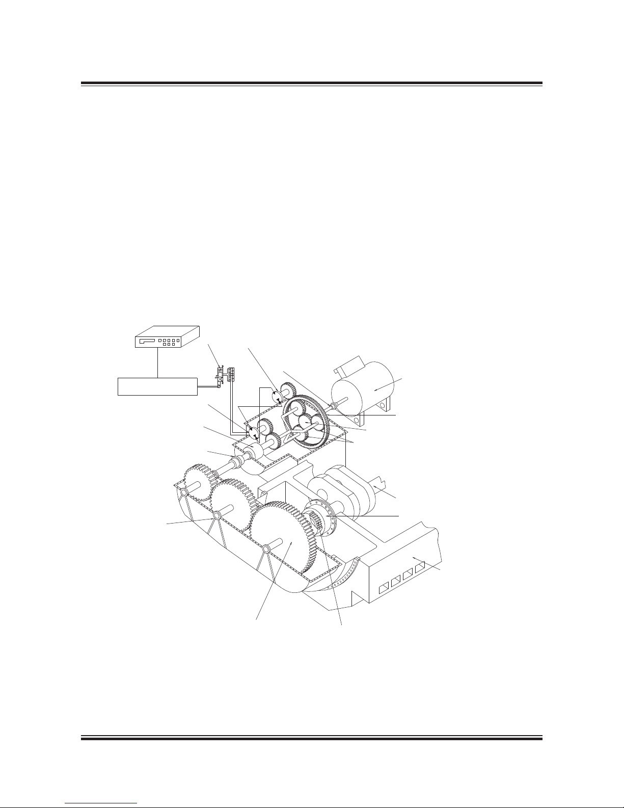
MAN B&W 4.01
Page 5 of 6
MAN Diesel
198 43 00 0.3M AN B&W 98-50 T II engines
The multidisc clutch, integrated into the gear input shaft, permits the engaging and disengaging
of the epicyclic gear, and thus the generator, from
the main engine during operation.
An electronic control system with a RENK controller ensures that the control signals to the main
electrical switchboard are identical to those for
the normal auxiliary generator sets. This applies to
ships with automatic synchronising and load sharing, as well as to ships with manual switchboard
operation.
Operating panel
in switchboard
RCFController
Hydrostatic pump
Multidisc clutch
Toothed coupling
Servo valve
Hydrostatic motor
Generator
Annulus ring
Sun wheel
Planetary gear wheel
Crankshaft
Bearings
Engine crankcase structure
Elastic damping coupling
Toothed coupling
1
st
crankshaft gear wheel
Toothed coupling
Fig. 4.01.04: Power take off with RENK constant frequency gear: BW III/RCF, option: 4 85 253
178 23 222.2
Internal control circuits and interlocking functions
between the epicyclic gear and the electronic
control box provide automatic control of the functions necessary for the reliable operation and
protection of the BW III/RCF unit. If any monitored
value exceeds the normal operation limits, a warning or an alarm is given depending upon the origin, severity and the extent of deviation from the
permissible values. The cause of a warning or an
alarm is shown on a digital display.
Page 66

MAN B&W 4.01
Page 6 of 6
MAN Diesel
198 43 00 0.3M AN B&W 98-50 T II engines
Yard deliveries are:
1. Cooling water pipes to the builton lubricating
oil cooling system, including the valves.
2. Electrical power supply to the lubricating oil
standby pump built on to the RCF unit.
3. Wiring between the generator and the operator
control panel in the switchboard.
4. An external permanent lubricating oil fillingup
connection can be established in connection
with the RCF unit. The system is shown in Fig.
4.03.03 ‘Lubricating oil system for RCF gear’.
The dosage tank and the pertaining piping
are to be delivered by the yard. The size of the
dosage tank is stated in the table for RCF gear
in ‘Necessary capacities for PTO/RCF’ (Fig.
4.03.02).
The necessary preparations to be made on
the engine are specified in Figs. 4.03.01a and
4.03.01b.
Additional capacities required for BW III/RCF
The capacities stated in the ‘List of capacities’ for
the main engine in question are to be increased
by the additional capacities for the crankshaft
gear and the RCF gear stated in Fig. 4.03.02.
Extent of delivery for BW III/RCF units
The delivery comprises a complete unit ready to
be builton to the main engine. Fig. 4.02.01 shows
the required space and the standard electrical
output range on the generator terminals.
Standard sizes of the crankshaft gears and the
RCF units are designed for: 700, 1200, 1800 and
2600 kW, while the generator sizes of make A. van
Kaick are:
Type
DSG
440 V
1800
kVA
60 Hz
r/min
kW
380 V
1500
kVA
50 Hz
r/min
kW
62 M24 707 566 627 501
62 L14 855 684 761 609
62 L24 1,056 845 940 752
74 M14 1,271 1,017 1,137 909
74 M24 1,432 1,146 1,280 1,024
74 L14 1,651 1,321 1,468 1,174
74 L24 1,924 1,539 1,709 1,368
86 K14 1,942 1,554 1,844 1,475
86 M14 2,345 1,876 2,148 1,718
86 L24 2,792 2,234 2,542 2,033
99 K14 3,222 2,578 2,989 2,391
In the event that a larger generator is required,
please contact MAN Diesel & Turbo.
If a main engine speed other than the nominal is
required as a basis for the PTO operation, it must
be taken into consideration when determining the
ratio of the crankshaft gear. However, it has no
influence on the space required for the gears and
the generator.
The PTO can be operated as a motor (PTI) as well
as a generator by making some minor modifications.
178 34 893.1
Page 67
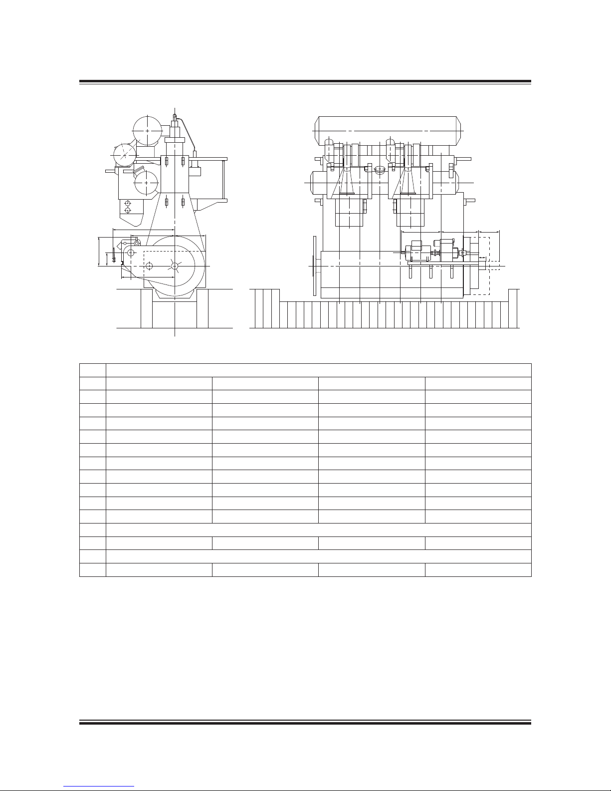
MAN B&W 4.02
Page 1 of 1
MAN Diesel
MAN B&W S65ME-C8/-GI
198 4 9 15-9.2
The stated kW at the generator terminals is available between 70% and 100% of the engine speed at specified MCR
Space requirements have to be investigated case by case on plants with 2,600 kW generator.
Dimension H: This is only valid for A. van Kaick generator type DSG, enclosure IP23, frequency = 60 Hz, speed = 1,800 r/min
Fig. 4.02.01: Space requirement for side mounted generator PTO/RCF type BWlll S65-C/RCF
kW generator
700 kW 1,200 kW 1,800 kW 2,600 kW
A 2,867 2,867 3,007 3,007
B 632 632 632 632
C 3,527 3,527 3,807 3,807
D 3,923 3,923 4,203 4,203
F 1,682 1,802 1,922 2,032
G 2,470 2,470 2,830 2,830
H 2,028 2,530 2,915 4,235
J 2,085 2,085 2,085 2,085
S 1,000 1,000 1,000 1,000
Z 500 500 500 500
System mass (kg) with generator:
23,750 27,500 39,100 52,550
System mass (kg) without generator:
21,750 24,850 34,800 47,350
178 65 39-0.1
F
D
A
J
Z
B
C
HGS
Cyl. 1
Page 68
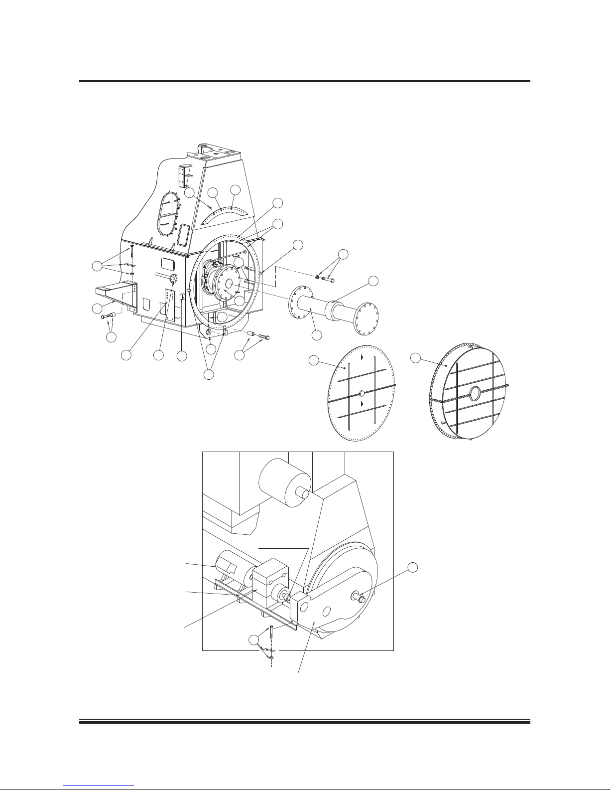
MAN B&W 4.03
Page 1 of 6
MAN Diesel
198 4 3 156.3MA N B&W 98 → 50MC/MC-C/ME/ME-C/ME-B/-GI
Toothed coupling
Alternator
Bedframe
RCF gear
(if ordered)
Crankshaft gear
16
15
13
14
12
10
21
2
11
6
2
2
8
18
17
3
4
5
7
1
2
9
19
20
22
Fig. 4.03.01a: Engine preparations for PTO, BWIII/RCF system
178 57 15-7.1
Engine preparations for PTO
Page 69

MAN B&W 4.03
Page 2 of 6
MAN Diesel
198 4 3 156.3MA N B&W 98 → 50MC/MC-C/ME/ME-C/ME-B/-GI
Pos.
1 Special face on bedplate and frame box
2 Ribs and brackets for supporting the face and machined blocks for alignment of gear or stator housing
3 Machined washers placed on frame box part of face to ensure that it is flush with the face on the bedplate
4 Rubber gasket placed on frame box part of face
5 Shim placed on frame box part of face to ensure that it is flush with the face of the bedplate
6 Distance tubes and long bolts
7 Threaded hole size, number and size of spring pins and bolts to be made in agreement with PTO maker
8 Flange of crankshaft, normally the standard execution can be used
9 Studs and nuts for crankshaft flange
10 Free flange end at lubricating oil inlet pipe (incl. blank flange)
11 Oil outlet flange welded to bedplate (incl. blank flange)
12 Face for brackets
13 Brackets
14 Studs for mounting the brackets
15 Studs, nuts and shims for mounting of RCF/generator unit on the brackets
16 Shims, studs and nuts for connection between crankshaft gear and RCF/generator unit
17 Engine cover with connecting bolts to bedplate/frame box to be used for shop test without PTO
18 Intermediate shaft between crankshaft and PTO
19 Oil sealing for intermediate shaft
20 Engine cover with hole for intermediate shaft and connecting bolts to bedplate/frame box
21 Plug box for electronic measuring instrument for checking condition of axial vibration damper
22 Tacho encoder for ME control system or MAN B&W Alpha lubrication system on MC engine
23 Tacho trigger ring for ME control system or MAN B&W Alpha lubrication system on MC engine
Pos. no: 1234567891011121314151617181920212223
BWIII/RCF AAAA B ABAAAAABBA AA
BWIII/CFE AAAA B ABAAAAABBA AA
BWII/RCF AA AAAA A
BWII/CFE AA AAAA A
BWI/RCF AAAA B AB A A A
BWI/CFE AAAA B ABAA A A A
DMG/CFE A A A B C A B A A A
A: Preparations to be carried out by engine builder
B: Parts supplied by PTO maker
C: See text of pos. no.
178 89 342.0
Table 4.03.01b: Engine preparations for PTO
Page 70
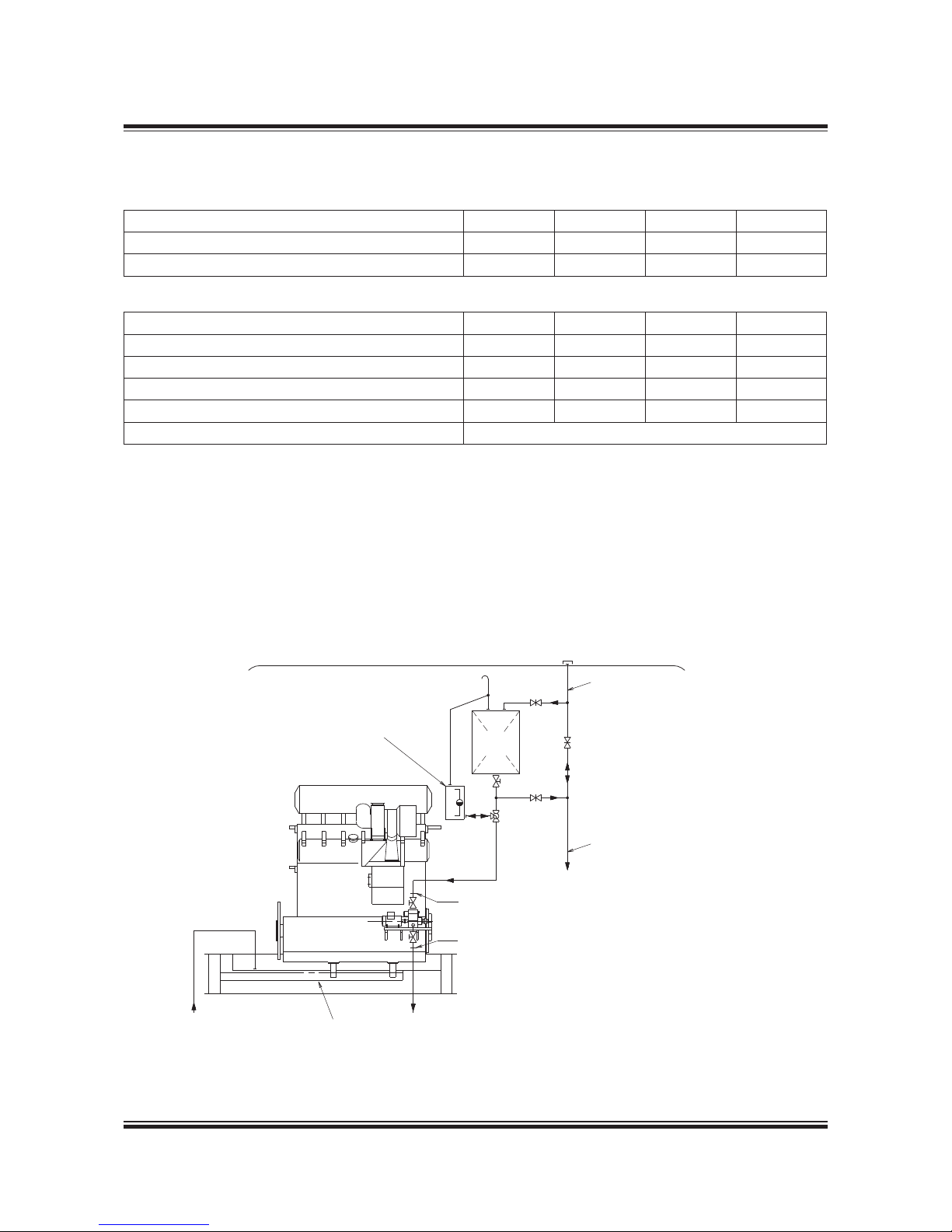
MAN B&W 4.03
Page 3 of 6
MAN Diesel
198 4 3 156.3MA N B&W 98 → 50MC/MC-C/ME/ME-C/ME-B/-GI
Crankshaft gear lubricated from the main engine lubricating oil system
The figures are to be added to the main engine capacity list:
Nominal output of generator kW 700 1,200 1,800 2,600
Lubricating oil flow m
3
/h 4.1 4.1 4.9 6.2
Heat dissipation kW 12.1 20.8 31.1 45.0
RCF gear with separate lubricating oil system:
Nominal output of generator kW 700 1,200 1,800 2,600
Cooling water quantity m
3
/ h 14.1 22.1 30.0 3 9. 0
Heat dissipation kW 55 92 134 180
El. power for oil pump kW 11.0 15.0 18.0 21.0
Dosage tank capacity m
3
0.40 0.51 0.69 0.95
El. power for Renk controller 24V DC ± 10%, 8 amp
From main engine:
Design lube oil pressure: 2.25 bar
Lube oil pressure at crankshaft gear: min. 1 bar
Lube oil working temperature: 50 °C
Lube oil type: SAE 30
Table 4.03.02: Necessary capacities for PTO/RCF, BW III/RCF system
178 33 850.0
Cooling water inlet temperature: 36 °C
Pressure drop across cooler: approximately 0.5 bar
Fill pipe for lube oil system store tank (~ø32)
Drain pipe to lube oil system drain tank (~ø40)
Electric cable between Renk terminal at gearbox
and operator control panel in switchboard: Cable
type FMGCG 19 x 2 x 0.5
The letters refer to the list of ‘Counterflanges’,
which will be extended by the engine builder,
when PTO systems are installed on the main engine
Fig. 4.03.03: Lubricating oil system for RCF gear
178 25 235.0
Filling pipe
Deck
To main engine
DR
Main
engine
Engine
oil
DS
S
S
C/D
To purifier
From purifier
Lube oil
bottom tank
The dimensions
of dosage tank
depend on actual
type of gear
C/D
Page 71
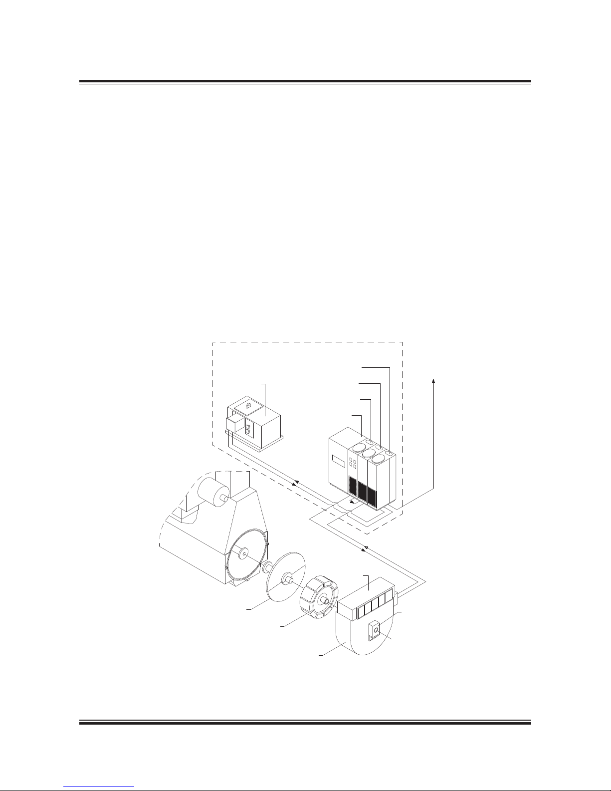
MAN B&W 4.03
Page 4 of 6
MAN Diesel
198 4 3 156.3MA N B&W 98 → 50MC/MC-C/ME/ME-C/ME-B/-GI
DMG/CFE Generators
Option: 4 85 259
Fig. 4.01.01 alternative 5, shows the DMG/CFE
(Direct Mounted Generator/Constant Frequency
Electrical) which is a low speed generator with
its rotor mounted directly on the crankshaft and
its stator bolted on to the frame box as shown in
Figs. 4.03.04 and 4.03.05.
The DMG/CFE is separated from the crankcase
by a plate and a labyrinth stuffing box.
The DMG/CFE system has been developed in cooperation with the German generator manufacturers Siemens and AEG, but similar types of generator can be supplied by others, e.g. Fuji, Taiyo
and Nishishiba in Japan.
For generators in the normal output range, the
mass of the rotor can normally be carried by the
foremost main bearing without exceeding the permissible bearing load (see Fig. 4.03.05), but this
must be checked by the engine manufacturer in
each case.
If the permissible load on the foremost main bearing is exceeded, e.g. because a tuning wheel
is needed, this does not preclude the use of a
DMG/CFE.
Fig. 4.03.04: Standard engine, with direct mounted generator (DMG/CFE)
178 06 733.1
Static frequency converter system
Synchronous
condenser
Cubicles:
Distributor
Converter
Excitation
Control
To switchboard
Cooler
Oil seal cover
Rotor
Stator housing
Support
bearing
Page 72
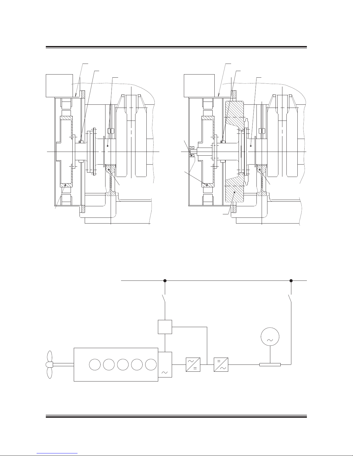
MAN B&W 4.03
Page 5 of 6
MAN Diesel
198 4 3 156.3MA N B&W 98 → 50MC/MC-C/ME/ME-C/ME-B/-GI
Stator shell
Stuffing box
Crankshaft
Air cooler
Main bearing No. 1
Pole wheel
Standard engine, with direct
mounted generator (DMG/CFE)
Support
bearing
Air cooler
Pole wheel
Stator shell
Stuffing box
Crankshaft
Main bearing No. 1
Standard engine, with direct mounted
generator and tuning wheel
Tuning wheel
Fig. 4.03.05: Standard engine, with direct mounted generator and tuning wheel
178 06 637.1
Mai
ns, constant frequency
Excitation converter
Synchronous
condenser
G
Diesel engine
DMG
Static converter
Smoothing reactor
Fig. 4.03.06: Diagram of DMG/CFE with static converter
178 56 553.1
Page 73

MAN B&W 4.03
Page 6 of 6
MAN Diesel
198 4 3 156.3MA N B&W 98 → 50MC/MC-C/ME/ME-C/ME-B/-GI
In such a case, the problem is solved by installing
a small, elastically supported bearing in front of
the stator housing, as shown in Fig. 4.03.05.
As the DMG type is directly connected to the
crankshaft, it has a very low rotational speed and,
consequently, the electric output current has a
low frequency – normally of the order of 15 Hz.
Therefore, it is necessary to use a static frequency
converter between the DMG and the main switchboard. The DMG/CFE is, as standard, laid out for
operation with full output between 100% and 75%
and with reduced output between 75% and 40%
of the engine speed at specified MCR.
Static converter
The static frequency converter system (see Fig.
4.03.06) consists of a static part, i.e. thyristors and
control equipment, and a rotary electric machine.
The DMG produces a threephase alternating
current with a low frequency, which varies in accordance with the main engine speed. This alternating current is rectified and led to a thyristor inverter producing a threephase alternating current
with constant frequency.
Since the frequency converter system uses a DC
intermediate link, no reactive power can be supplied to the electric mains. To supply this reactive
power, a synchronous condenser is used. The
synchronous condenser consists of an ordinary
synchronous generator coupled to the electric
mains.
Extent of delivery for DMG/CFE units
The delivery extent is a generator fully builton
to the main engine including the synchronous
condenser unit and the static converter cubicles
which are to be installed in the engine room.
The DMG/CFE can, with a small modification,
be operated both as a generator and as a motor
(PTI).
Yard deliveries are:
1. Installation, i.e. seating in the ship for the synchronous condenser unit and for the static
converter cubicles
2. Cooling water pipes to the generator if water
cooling is applied
3. Cabling.
The necessary preparations to be made on the
engine are specified in Fig. 4.03.01a and Table
4.03.01b.
SMG/CFE Generators
The PTO SMG/CFE (see Fig. 4.01.01 alternative 6)
has the same working principle as the PTO DMG/
CFE, but instead of being located on the front end
of the engine, the alternator is installed aft of the
engine, with the rotor integrated on the intermediate shaft.
In addition to the yard deliveries mentioned for the
PTO DMG/CFE, the shipyard must also provide
the foundation for the stator housing in the case
of the PTO SMG/CFE.
The engine needs no preparation for the installation of this PTO system.
Page 74
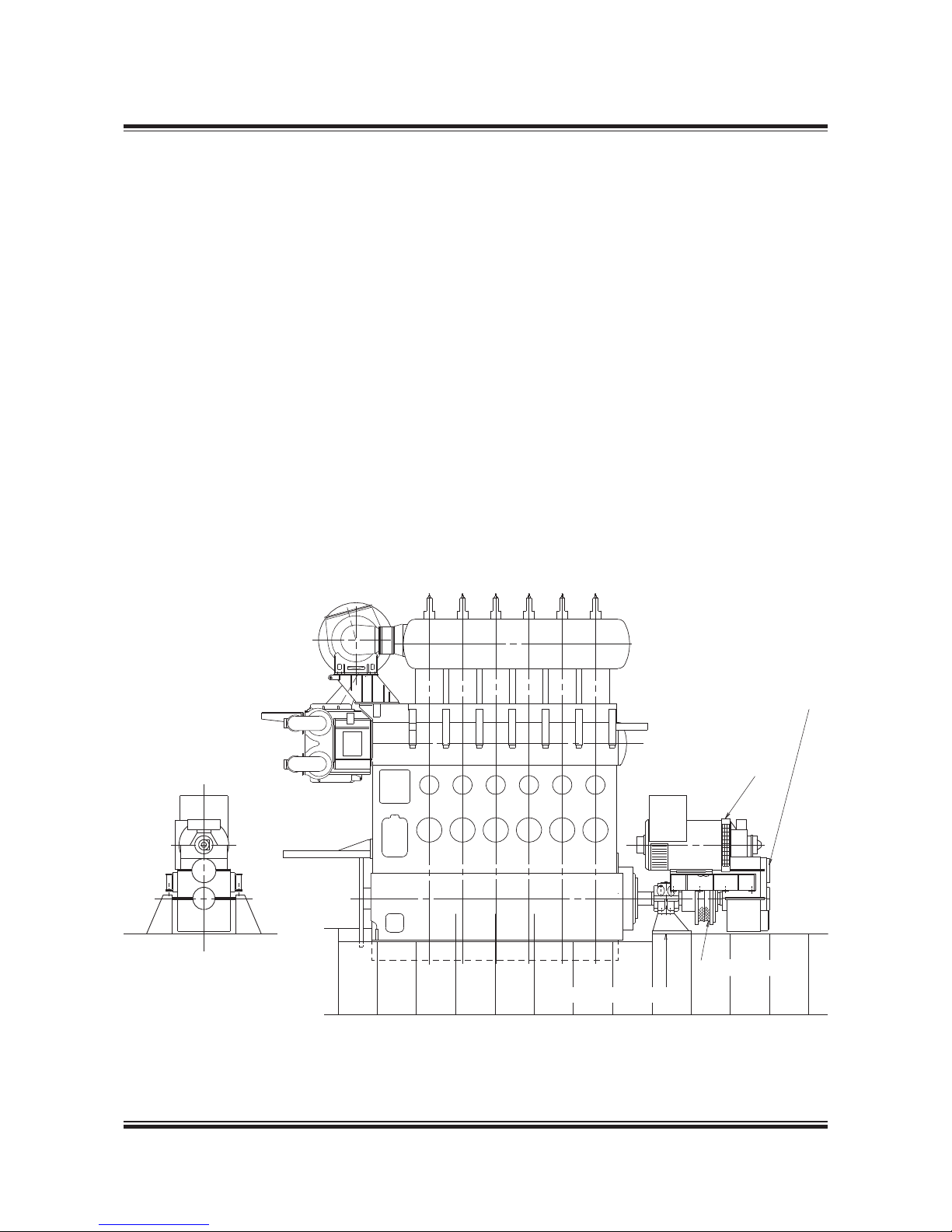
MAN B&W 4.04
Page 1 of 3
MAN Diesel
198 43 16 8.8MAN B& W 70 – 26 engi nes
PTO type: BW II/GCR
Power Take Off/Gear Constant Ratio
The PTO system type BW II/GCR illustrated in Fig.
4.01.01 alternative 5 can generate electrical power
on board ships equipped with a controllable pitch
propeller, running at constant speed.
The PTO unit is mounted on the tank top at the
fore end of the engine see Fig. 4.04.01. The PTO
generator is activated at sea, taking over the electrical power production on board when the main
engine speed has stabilised at a level corresponding to the generator frequency required on board.
The installation length in front of the engine, and
thus the engine room length requirement, naturally exceeds the length of the engine aft end
mounted shaft generator arrangements. However,
there is some scope for limiting the space requirement, depending on the configuration chosen.
PTO type: BW IV/GCR
Power Take Off/Gear Constant Ratio
The shaft generator system, type PTO BW IV/
GCR, installed in the shaft line (Fig. 4.01.01 alternative 6) can generate power on board ships
equipped with a controllable pitch propeller running at constant speed.
The PTO system can be delivered as a tunnel gear
with hollow flexible coupling or, alternatively, as
a generator stepup gear with thrust bearing and
flexible coupling integrated in the shaft line.
The main engine needs no special preparation for
mounting these types of PTO systems as they are
connected to the intermediate shaft.
The PTO system installed in the shaft line can also
be installed on ships equipped with a fixed pitch
propeller or controllable pitch propeller running in
Fig. 4.04.01: Generic outline of Power Take Off (PTO) BW II/GCR
178 18 225.0
Support bearing, if required
Elastic coupling
Step-up gear
Generator
Page 75
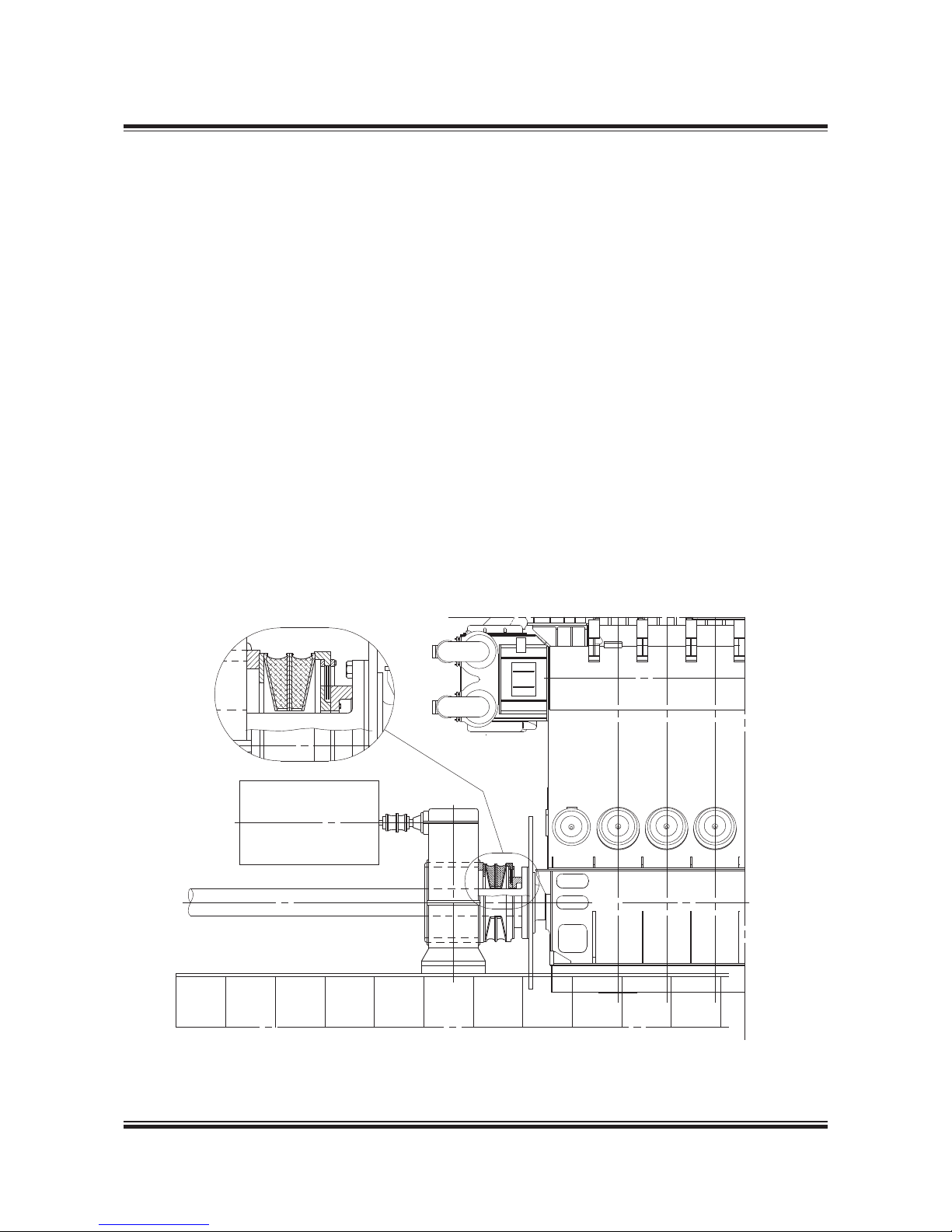
MAN B&W 4.04
Page 2 of 3
MAN Diesel
198 43 16 8.8MAN B& W 70 – 26 engi nes
combinator mode. This will, however, require an
additional RENK Constant Frequency gear (Fig.
4.01.01 alternative 2) or additional electrical equipment for maintaining the constant frequency of
the generated electric power.
Tunnel gear with hollow flexible coupling
This PTO system is normally installed on ships
with a minor electrical power take off load compared to the propulsion power, up to approximately 25% of the engine power.
The hollow flexible coupling is only to be dimensioned
for the maximum electrical load of the power take off
system and this gives an economic advantage for minor
power take off loads compared to the system with an
ordinary flexible coupling integrated in the shaft line.
The hollow flexible coupling consists of flexible
segments and connecting pieces, which allow
replacement of the coupling segments without
dismounting the shaft line, see Fig. 4.04.02.
Fig. 4.04.02: Generic outline of BW IV/GCR, tunnel gear
178 18 250.1
Generator stepup gear and flexible coupling
integrated in the shaft line
For higher power take off loads, a generator
stepup gear and flexible coupling integrated in
the shaft line may be chosen due to first costs of
gear and coupling.
The flexible coupling integrated in the shaft line
will transfer the total engine load for both propulsion and electrical power and must be dimensioned accordingly.
The flexible coupling cannot transfer the thrust
from the propeller and it is, therefore, necessary
to make the gearbox with an integrated thrust
bearing.
This type of PTO system is typically installed on
ships with large electrical power consumption,
e.g. shuttle tankers.
Page 76
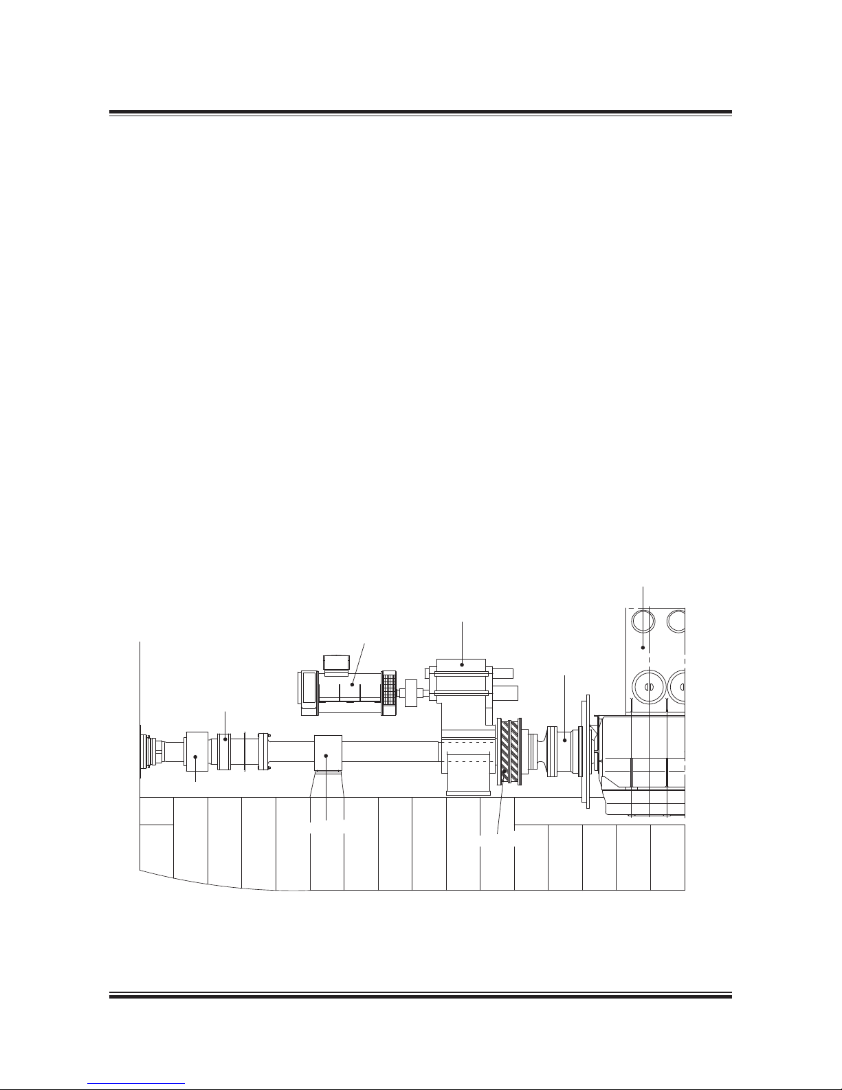
MAN B&W 4.04
Page 3 of 3
MAN Diesel
198 43 16 8.8MAN B& W 70 – 26 engi nes
Auxiliary Propulsion System/Take Home System
From time to time an Auxiliary Propulsion System/
Take Home System capable of driving the CP propeller by using the shaft generator as an electric
motor is requested.
MAN Diesel & Turbo can offer a solution where
the CP propeller is driven by the alternator via a
twospeed tunnel gear box. The electric power is
produced by a number of GenSets. The main engine is disengaged by a clutch (RENK PSC) made
as an integral part of the shafting. The clutch is installed between the tunnel gear box and the main
engine, and conical bolts are used to connect and
disconnect the main engine and the shafting.
See Figure 4.04.03.
A thrust bearing, which transfers the auxiliary propulsion propeller thrust to the engine thrust bearing when the clutch is disengaged, is built into the
RENK PSC clutch. When the clutch is engaged,
the thrust is transferred statically to the engine
thrust bearing through the thrust bearing built into
the clutch.
To obtain high propeller efficiency in the auxiliary
propulsion mode, and thus also to minimise the
auxiliary power required, a twospeed tunnel gear,
which provides lower propeller speed in the auxiliary propulsion mode, is used.
The twospeed tunnel gear box is made with a
friction clutch which allows the propeller to be
clutched in at full alternator/motor speed where
the full torque is available. The alternator/motor is
started in the declutched condition with a start
transformer.
The system can quickly establish auxiliary propulsion from the engine control room and/or bridge,
even with unmanned engine room.
Reestablishment of normal operation requires
attendance in the engine room and can be done
within a few minutes.
Fig. 4.04.03: Auxiliary propulsion system
178 57 16-9.0
Main engine
Renk PSC cluth
Two-speed tunnel gearbox
Generato r/motor
Oil distribution ring
Hydraulic coupling
Intermediate bearing
Flexible coupling
Page 77

MAN B&W 4.05
Page 1 of 9
MAN Diesel
198 57 97-7.5
MAN B&W 9 8-60 engin es
Waste Heat Recovery Systems (WHRS)
Due to the increasing fuel prices seen from 2004
and onwards many shipowners have shown interest in efficiency improvements of the power systems on board their ships. A modern two-stroke
diesel engine has one of the highest thermal efficiencies of today’s power systems, but even this
high efficiency can be improved by combining the
diesel engine with other power systems.
One of the possibilities for improving the efficiency is to install one or more systems utilising some
of the energy in the exhaust gas after the twostroke engine, which in MAN Diesel & Turbo terms
is designated as WHRS (Waste Heat Recovery
Systems).
WHRS can be divided into different types of subsystems, depending on how the system utilises
the exhaust gas energy. Choosing the right system for a specific project depends on the electricity demand on board the ship and the acceptable
first cost for the complete installation. MAN Diesel
& Turbo uses the following designations for the
current systems on the market:
• PTG (Power Turbine Generator):
An exhaust gas driven turbine connected to a
generator via a gearbox.
• STG (Steam Turbine Generator):
A steam driven turbine connected to a generator
via a gearbox. The steam is produced in a large
exhaust gas driven boiler installed on the main
engine exhaust gas piping system.
• Combined Turbines:
A combination of the two first systems. The ar-
rangement is often that the power turbine is
connected to the steam turbine via a gearbox
and the steam turbine is further connected to a
large generator, which absorbs the power from
both turbines.
The PTG system will produce power equivalent
to approx. 3.5% of the main engine SMCR, when
the engine is running at SMCR. For the STG system this value is between 5 and 7% depending
on the system installed. When combining the two
systems, a power output equivalent to 10% of the
main engine’s SMCR is possible, when the engine
is running at SMCR.
The WHRS output depends on the main engine
rating and whether service steam consumption
must be deducted or not.
As the electrical power produced by the system
needs to be used on board the ship, specifying
the correct size system for a specific project must
be considered carefully. In cases where the electrical power consumption on board the ship is low,
a smaller system than possible for the engine type
may be considered. Another possibility is to install
a shaft generator/motor to absorb excess power
produced by the WHRS. The main engine will then
be unloaded, or it will be possible to increase the
speed of the ship, without penalising the fuel bill.
Because the energy from WHRS is taken from the
exhaust gas of the main engine, this power produced can be considered as ”free”. In reality, the
main engine SFOC will increase slightly, but the
gain in electricity production on board the ship will
far surpass this increase in SFOC. As an example,
the SFOC of the combined output of both the engine and the system with power and steam turbine
can be calculated to be as low as 152 g/kWh (ref.
LCV 42,700 kJ/kg).
Page 78
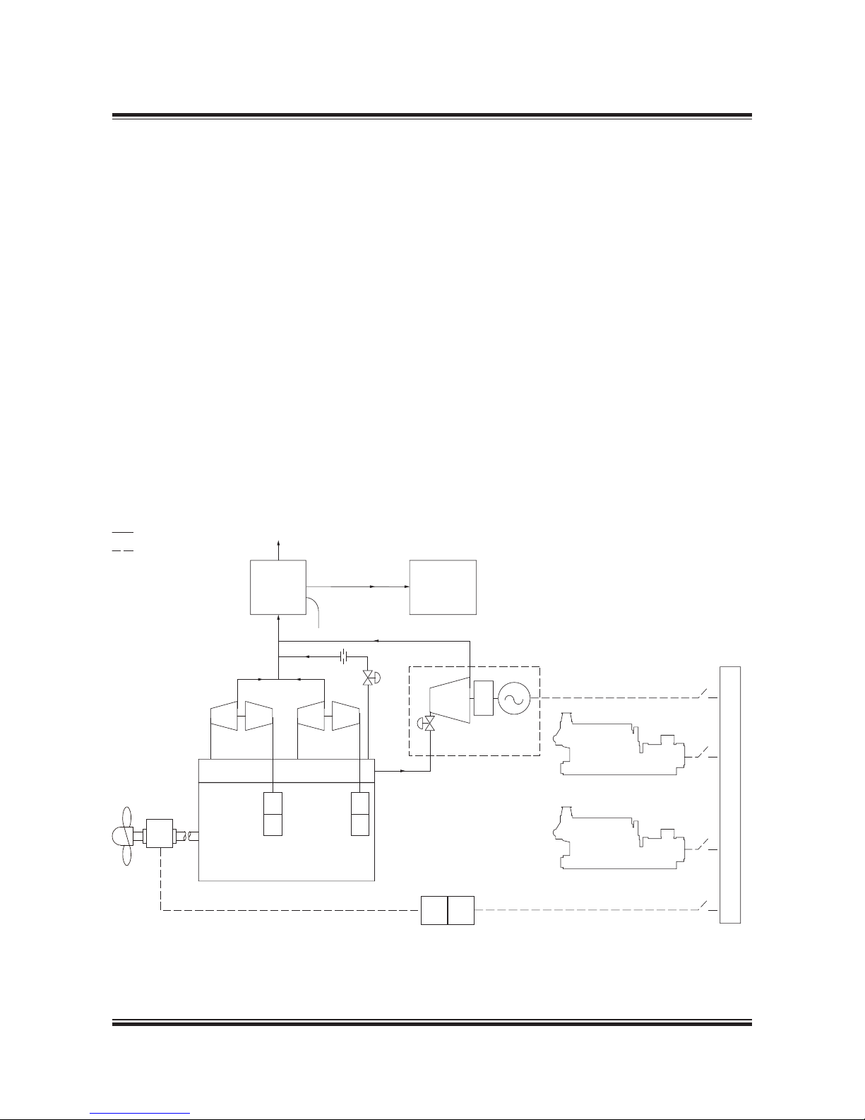
MAN B&W 4.05
Page 2 of 9
MAN Diesel
MAN B&W 9 8-60 engin es
198 57 97-7.5
Exhaust gas
To funnel
TCS-PTG
Frequency converter
Main
switchboard
GenSet
GenSet
Piping
Electrical wiring
Exhaust gas receiver
Main engine
Scavenge
air cooler
TC TC
PTO/
PTI
Power
turbine
~/~ OO
Steam
boiler
Steam for
heating
services
178 63 80-5.0
Fig. 4.05.01: PTG diagram
Power Turbine Generator (PTG)
The power turbines of today are based on the different turbocharger suppliers’ newest designs of
high efficiency turbochargers, i.e. MAN TCA, ABB
A-L and Mitsubishi MET turbochargers.
MAN Diesel & Turbo offers PTG solutions called
TCS-PTG in the range from approx. 1,000 kW to
5,000 kW, see Fig. 4.05.02.
The power turbine basically is the turbine side of
a normal high-efficient turbocharger with some
modifications to the bearings and the turbine
shaft. This is in order to be able to connect it to
a gearbox instead of the normal connection to
the compressor side. The power turbine will be
installed on a separate exhaust gas pipe from the
exhaust gas receiver, which bypasses the turbochargers.
The performance of the PTG and the main engine
will depend on a careful matching of the engine
turbochargers and the power turbine, for which
reason the turbocharger/s and the power turbine
need to be from the same manufacturer. In Fig.
4.05.01, a diagram of the PTG arrangement is
shown.
The newest generation of high efficiency turbochargers allows bypassing of some of the main
engine exhaust gas, thereby creating a new balance of the air flow through the engine. In this
way, it is possible to extract power from the power
turbine equivalent to 3.5% of the main engine’s
SMCR, when the engine is running at SMCR.
Page 79
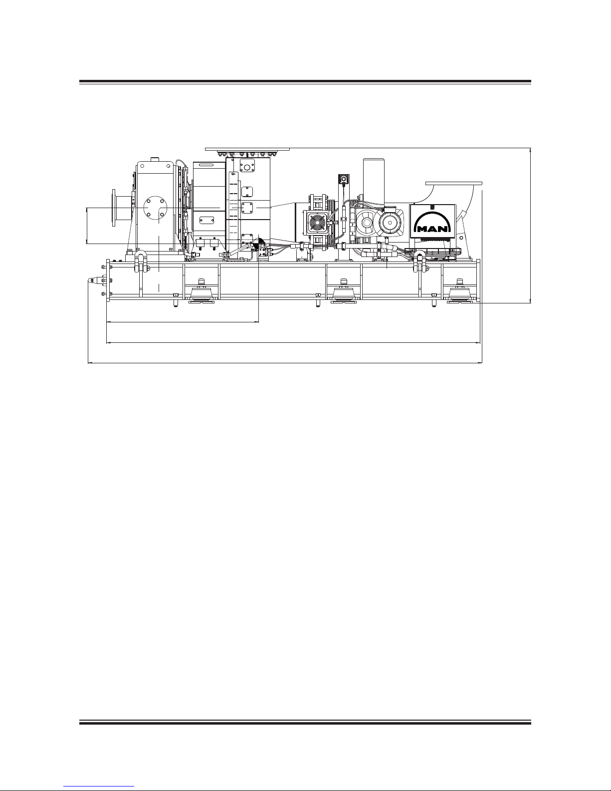
MAN B&W 4.05
Page 3 of 9
MAN Diesel
198 57 97-7.5
MAN B&W 9 8-60 engin es
178 63 81-7.0
Fig. 4.05.02: MAN Diesel & Turbo 1,500 kW TCS-PTG solution
320
1,363
3,345
Frame for powertrain and piping system
1,389
3,531
Page 80
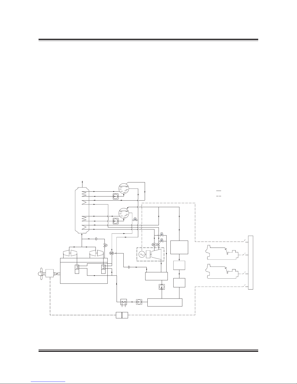
MAN B&W 4.05
Page 4 of 9
MAN Diesel
MAN B&W 9 8-60 engin es
198 57 97-7.5
HPsteam
for heating
services
Condenser
Feedwater
pump
Condensater
pump
LP steam drum
HP steam
drum
HP circ. p.
LP circ. pump
LP evaporator
Piping
Electrical wiring
LP superheater
HP evaporator
HP uperheater
Exhaust gas
STG unit
LP
HP
Exh. ga s boiler
sections:
LP
HP
Jacket
water
Hot well
tank
Buffer
tank
Exhaust gas receiver
Main engine
Scavenge
air cooler
TC TC
Vacuum deaerator tank
PTO/
PTI
Steam
turbine
Frequency converter
Main
switchboard
GenSet
GenSet
~/~ OO
178 63 82-9.0
Fig. 4.05.03: STG system diagram
In most cases the exhaust gas pipe system of
the main engine is equipped with a boiler system.
With this boiler, some of the energy in the exhaust
gas is utilised to produce steam for use on board
the ship.
If the engine is WHR matched, the exhaust gas
temperature will be between 50°C and 65°C higher
than on a conventional engine, which makes it
possible to install a larger boiler system and,
thereby, produce more steam. In short, MAN
Diesel & Turbo designates this system STG. Fig.
4.05.03 shows an example of the STG diagram.
For WHR matching the engine, a bypass is installed to increase the temperature of the exhaust
gas and improve the boiler output. The bypass
valve is controlled by the engine control system.
The extra steam produced in the boiler can be
utilised in a steam turbine, which can be used to
drive a generator for power production on board
the ship. A STG system could be arranged as
shown in Fig. 4.05.04, where a typical system size
is shown with the outline dimensions.
The steam turbine can either be a single or dual
pressure turbine, depending on the size of the
system. Steam pressure for a single pressure system is 7 to 10 bara, and for the dual pressure system the high-pressure cycle will be 9 to 10 bara
and the low-pressure cycle will be 4 to 5 bara.
Steam Turbine Generator (STG)
Page 81
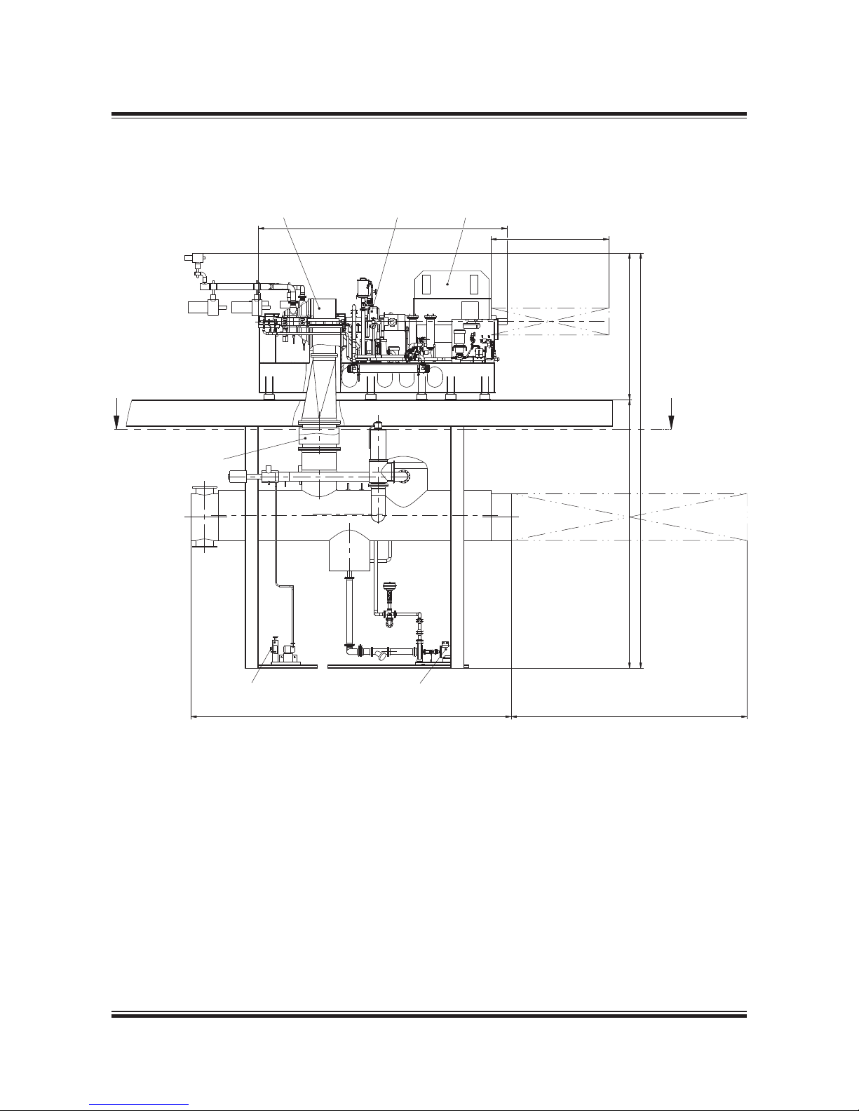
MAN B&W 4.05
Page 5 of 9
MAN Diesel
198 57 97-7.5
MAN B&W 9 8-60 engin es
178 63 83-0.1
Fig. 4.05.04: STG steam turbine generator arrangement with condenser - typical arrangement
Steam turbine
Expansions joint
Condenser
Exhaust
steam
Appr. 7,500
Approx. 4,000
Approx. 4,500
Approx. 12,500
Approx. 8,000
Approx. 8,000
Conpensate pumpEvacuation unit
Approx. 9,500
CC
Maintenance space
Reduction gear Generator
Maintenance space
Page 82
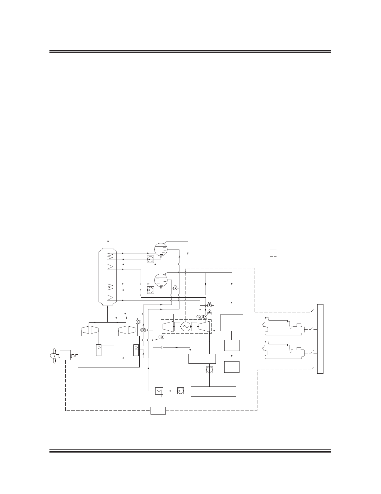
MAN B&W 4.05
Page 6 of 9
MAN Diesel
MAN B&W 9 8-60 engin es
198 57 97-7.5
Condenser
Feedwater
pump
Condensater
pump
LP steam drum
HP steam
drum
HP circ. p.
LP circ. pump
LP evaporator
LP superheater
HP evaporator
HP superheater
Exhaust gas
ST & PT unit
LP
HP
Exh. gas boiler
sections:
LP
HP
Jacket
water
Piping
Electrical wiring
Exhaust gas receiver
Main engine
Scavenge
air cooler
TC TC
PTO/
PTI
Vacuum deaerator tank
HPsteam
for heating
services
Hot well
tank
Buffer
tank
Power
turbine
Steam
turbine
Frequency converter
Main
switchboard
GenSet
GenSet
~/~
OO
Fig. 4.05.05: Full WHRS with both steam and power turbines
178 63 84-2.0
Because the installation of the power turbine also
will result in an increase of the exhaust gas temperature after the turbochargers, it is possible to
install both the power turbine, the larger boiler and
steam turbine on the same engine. This way, the
energy from the exhaust gas is utilised in the best
way possible by today’s components.
When looking at the system with both power and
steam turbine, quite often the power turbine and
the steam turbine are connected to the same
generator. In some cases, it is also possible to
have each turbine on a separate generator. This
is, however, mostly seen on stationary engines,
where the frequency control is simpler because of
the large grid to which the generator is coupled.
For marine installations the power turbine is, in
most cases, connected to the steam turbine via a
gearbox, and the steam turbine is then connected
to the generator. It is also possible to have a generator with connections in both ends, and then
connect the power turbine in one end and the
steam turbine in the other. In both cases control of
one generator only is needed.
For dimensions of a typical full WHRS see
Fig. 4.05.06.
As mentioned, the systems with steam turbines
require a larger boiler to be installed. The size of
the boiler system will be considerably bigger than
the size of an ordinary boiler system, and the actual boiler size has to be calculated from case to
case. Casing space for the exhaust boiler must be
reserved in the initial planning of the ship’s machinery spaces.
Full WHRS Steam and Power Turbines Combined
Page 83
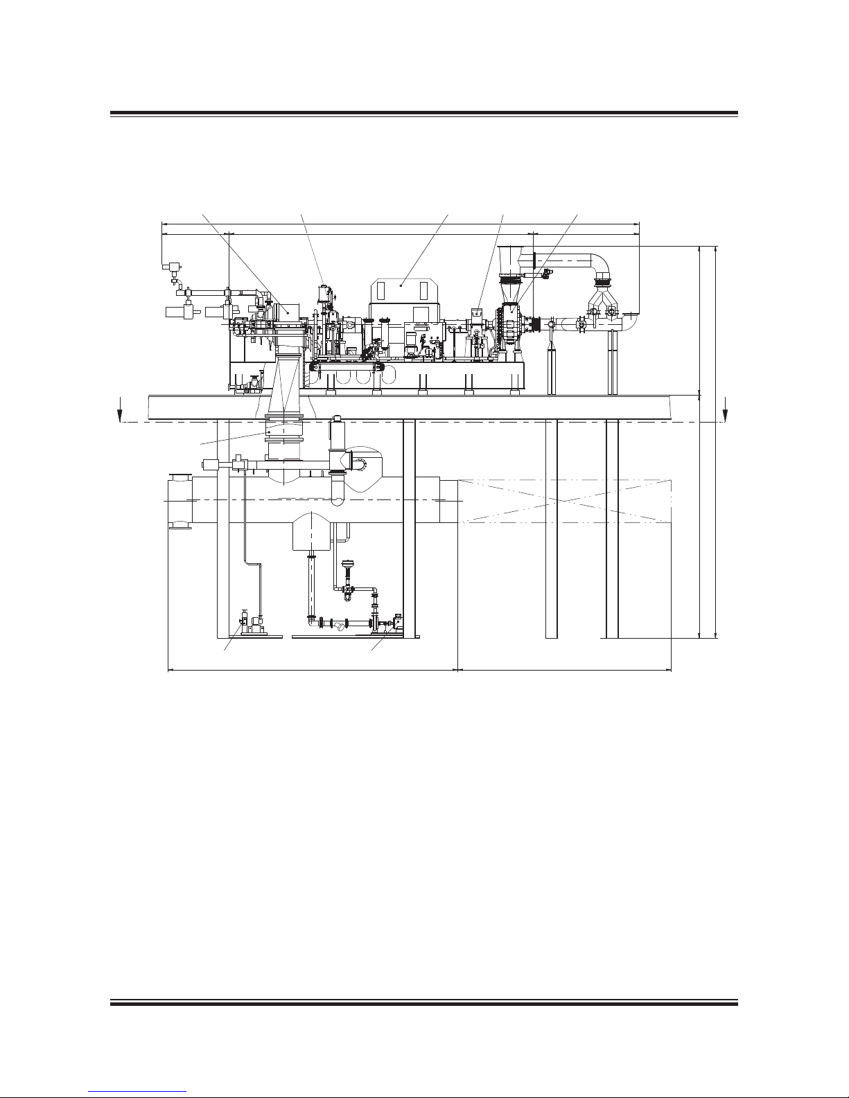
MAN B&W 4.05
Page 7 of 9
MAN Diesel
198 57 97-7.5
MAN B&W 9 8-60 engin es
178 63 85-4.1
Fig. 4.05.06: Full ST & PT full waste heat recovery unit arrangement with condenser - typical arrangement
Steam turbine
Expansions joint
Exhaust
steam
Approx. 2,500
Approx. 16,000
Approx. 10,000
Approx. 3,500
Approx. 5,000
Approx. 13,000
CC
Approx. 8,000
Approx. 8,000
Approx. 9,500
Conpensate pump
Evacuation unit
Reduction gear Reduction gear Power turbineGenerator
Maintenance space
Page 84

MAN B&W 4.05
Page 8 of 9
MAN Diesel
MAN B&W S 65MC-C8 .2-TII, S6 5ME-C8.2 /-GI-TII
198 89 22- 8.0
WHRS generator output
Because all the components come from different
manufacturers, the final output and the system efficiency have to be calculated from case to case.
However, Table 4.05.07 shows a guidance of possible outputs based on theoretically calculated
outputs from the system.
Note 1: The above given preliminary WHRS generator outputs is based on HP service steam consumption of 0.3 ton/h and LP service steam consumption of 0.7 ton/h for the ship at ISO condition.
Note 2: 75% SMCR is selected due to the EEDI focus on the engine load.
Detailed information about the different WHRS
systems is found in our publication:
Waste Heat Recovery System (WHRS)
The publication is available at
www.marine.man.eu → ’Two-Stroke’ → ’Technical
Papers’.
Guidance output of WHR for S65MC-C8.2-TII and S65ME-C8.2/-GI-TII engine rated in L1 at ISO conditions
Cyl.
Engine power PTG STG
Full WHRS with
combined turbines
% SMCR kW kWe kWe kWe
5
100 14,350 519 718 1,180
75 10,763 330 540 785
6
100 17,220 627 920 1,422
75 12,915 403 654 949
7
100 20,090 735 1,081 1,667
75 15,068 478 771 1,115
8
100 22,960 845 1,244 1,915
75 17,220 556 891 1,283
Table 4.05.07:
Theoretically calculated outputs
Page 85
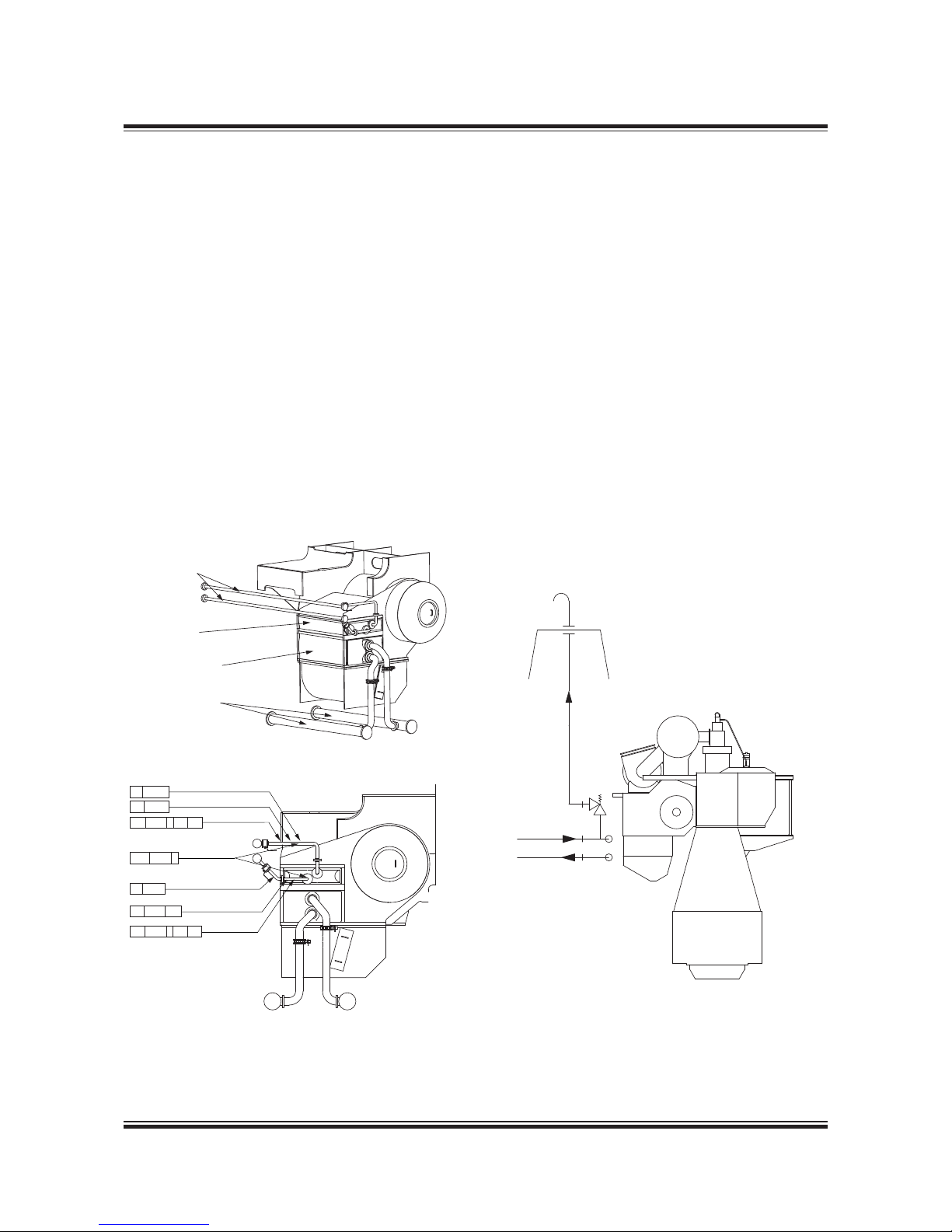
MAN B&W 4.05
Page 9 of 9
MAN Diesel
198 82 88 -9.1
MAN B&W 98-60 MC/MC-C/ME/ME-C/ME-B/-GI engines
Waste Heat Recovery Element and Safety Valve
The boiler water or steam for power generator is
preheated in the Waste Heat Recovery (WHR) element, also called the first-stage air cooler.
The WHR element is typically built as a high-pressure water/steam heat exchanger which is placed
on top of the scavenge air cooler, see Fig. 4.05.08.
Full water flow must be passed through the WHR
element continuously when the engine is running.
This must be considered in the layout of the
steam feed water system (the WHR element supply heating). Refer to our ‘WHR element specification’ which is available from MAN Diesel & Turbo,
Copenhagen.
Fig. 4.05.08: WHR element on Scavenge air cooler
Scavenge air cooler
Cooling wa ter pipes
Air cooler
Cooling wa ter pipes
WHR air co oler
Scavenge a ir cooler
WHR air co oler
TI 8442
TE 8442
TI 8441
PT 8444 I AH AL
TE 8441 AH
PT 8440 I A H AL
PDT 8443 I
521 39 06-2.1.1
Fig. 4.05.09: WHR safety valve blow-off through connection ‘W’ to the funnel
BP
W
Main
Engine
BN
Top of funnel
The let ters refer to list
of ‘Counterflanges’
078 63 84-0.0.1
Safety valve and blow-off
In normal operation, the temperature and pressure
of the WHR element is in the range of 140-150 ˚C
and 8-21 bar respectively.
In order to prevent leaking components from
causing personal injuries or damage to vital parts
of the main engine, a safety relief valve will blow
off excess pressure. The safety relief valve is connected to an external connection, ‘W’, see Fig.
4.05.09.
Connection ‘W’ must be passed to the funnel or
another free space according to the class rules for
steam discharge from safety valve.
As the system is pressurised according to class
rules, the safety valve must be type approved.
Page 86
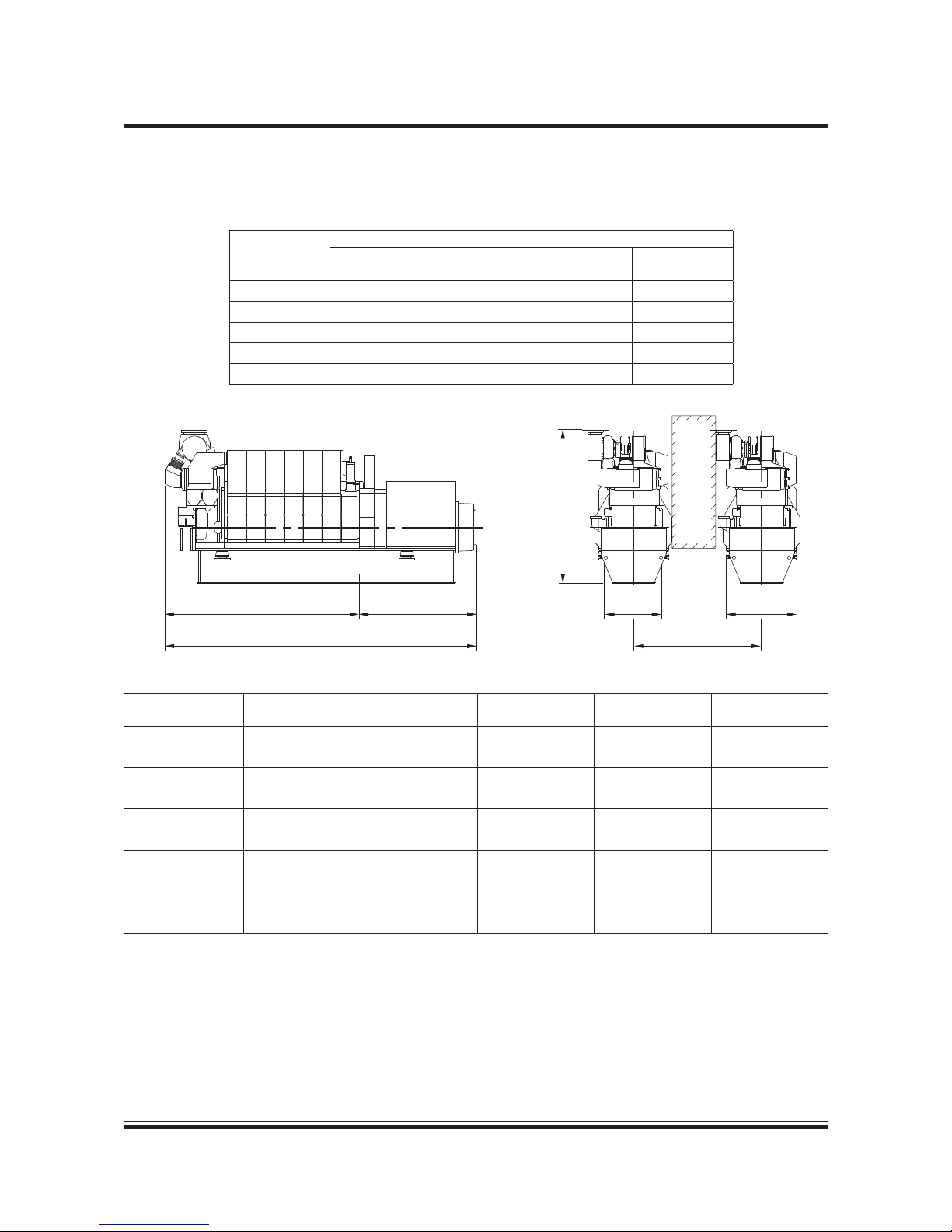
MAN Diesel 4.06
Page 1 of 3
MAN Diesel
198 82 80 4.0MA N B&W 80-26M C/MC-C/ME /ME-C/ME- B/-GI-TII engines
L16/24-Tll GenSet Data
Bore: 160 mm Stroke: 240 mm
Power layout
1,200 r/min 60 Hz 1,000 r/min 50 Hz
Eng. kW Gen. kW Eng. kW Gen. kW
5L16/24 500 475 450 430
6L16/24 660 625 570 542
7L16/24 770 730 665 632
8L16/24 880 835 760 722
9L16/24 990 940 855 812
No. of Cyls. A (mm) * B (mm) * C (mm) H (mm)
**Dry weight
GenSet (t)
5 (1,000 r/min) 2,751 1,400 4,151 2,457 9.5
5 (1,200 r/min) 2,751 1,400 4,151 2,457 9.5
6 (1,000 r/min) 3,026 1,490 4,516 2,457 10.5
6 (1,200 r/min) 3,026 1,490 4,516 2,457 10.5
7 (1,000 r/min) 3,501 1,585 5,086 2,457 11.4
7 (1,200 r/min) 3,501 1,585 5,086 2,495 11.4
8 (1,000 r/min) 3,776 1,680 5,456 2,495 12.4
8 (1,200 r/min) 3,776 1,680 5,456 2,495 12.4
9 (1,000 r/min) 4,051 1,680 5,731 2,495 13.1
9 (1,200 r/min) 4,051 1,680 5,731 2,495 13.1
178 23 031.0
P Free passage between the engines, width 600 mm and height 2,000 mm
Q Min. distance between engines: 1,800 mm
* Depending on alternator
** Weight incl. standard alternator (based on a Leroy Somer alternator)
All dimensions and masses are approximate and subject to change without prior notice.
178 33 874.4
Fig. 4.06.01: Power and outline of L16/24, IMO Tier II
A
C
B
H
P
Q
830 1000
Page 87

MAN Diesel 4.06
Page 2 of 3
MAN Diesel
MAN B& W 80-26 MC/MC-C/M E/ME-C/ME -B/-GI-TII engine s 198 82 80 4.0
L16/24-Tll GenSet Data
Fig. 4.06.02a: List of capacities for L16/24 1,000 rpm, IMO Tier II
5L:90 kW/cyl., 6L-9L: 95 kW/Cyl. at 1,000 rpm
Reference Condition: Tropic
Air temperature
LT-water temperature inlet engine (from system)
Air pressure
Relative humidity
°C
°C
bar
%
45
38
1
50
Temperature basis
Setpoint HT cooling water engine outlet
1)
Setpoint LT cooling water engine outlet
2)
Setpoint Lube oil inlet engine
°C
°C
°C
79 nominal (Range of mechanical thermostatic element 77 to 85)
35 nominal (Range of mechanical thermostatic element 29 to 41)
66 nominal (Range of mechanical thermostatic element 63 to 72)
Number of Cylinders
-
56789
Engine output
Speed
kW
rpm
450 570 665 760 855
1,000
Heat to be dissipated
3)
Cooling water (C.W.) Cylinder
Charge air cooler; cooling water HT
Charge air cooler; cooling water LT
Lube oil (L.O.) cooler
Heat radiation engine
kW
kW
kW
kW
kW
107 135 158 181 203
138 169 192 213 234
56 69 80 91 102
98 124 145 166 187
15 19 23 26 29
Flow rates
4)
Internal (inside engine)
HT circuit (cylinder + charge air cooler HT stage)
LT circuit (lube oil + charge air cooler LT stage)
Lube oil
External (from engine to system)
HT water flow (at 40°C inlet)
LT water flow (at 38°C inlet)
m3/h
m3/h
m3/h
m3/h
m3/h
10.9 12.7 14.5 16.3 18.1
15.7 18.9 22 25.1 28.3
18 18 30 30 30
5.2 6.4 7.4 8.3 9.2
15.7 18.9 22 25.1 28.3
Air data
Temperature of charge air at charge air cooler outlet
Air flow rate
Charge air pressure
Air required to dissipate heat radiation (engine)(t
2-t1
=10°C)
°C
m3/h
5)
kg/kWh
bar
m3/h
49 51 52 54 55
2,721 3,446 4,021 4,595 5,169
6.62 6.62 6.62 6.62 6.62
4.13
4,860 6,157 7,453 8,425 9,397
Exhaust gas data
6)
Volume flow (temperature turbocharger outlet) Mass flow
Temperature at turbine outlet
Heat content (190°C)
Permissible exhaust back pressure
m3/h
7)
t/h
°C
kW
mbar
5,710 7,233 8,438 9,644 10,849
3.1 3.9 4.5 5.2 5.8
375 375 375 375 375
170 216 252 288 324
< 30
Pumps
a) Engine driven pumps
HT circuit cooling water (2.5 bar)
LT circuit cooling water (2.5 bar)
Lube oil (4.5 bar)
b) External pumps
8)
Diesel oil pump (5 bar at fuel oil inlet A1)
Fuel oil supply pump (4 bar discharge pressure)
Fuel oil circulating pump (8 bar at fuel oil inlet A1)
m3/h
m3/h
m3/h
m3/h
m3/h
m3/h
10.9 12.7 14.5 16.3 18.1
15.7 18.9 22 25.1 28.3
18 18 30 30 30
0.32 0.40 0.47 0.54 0.60
0.15 0.19 0.23 0.26 0.29
0.32 0.40 0.47 0.54 0.60
Starting air data
Air consumption per start, incl. air for jet assist (IR/TDI)
Air consumption per start, incl. air for jet assist (Gali)
Nm
3
Nm
3
0.47 0.56 0.65 0.75 0.84
0.80 0.96 1.12 1.28 1.44
1) LT cooling water flow first through LT stage charge air cooler, then
through lube oil cooler, water temperature outlet engine regulated by
mechanical thermostat.
2) HT cooling water flow first through HT stage charge air cooler, then
through water jacket and cylinder head, water temperature outlet engine regulated by mechanical thermostat.
3) Tolerance: + 10% for rating coolers, - 15% for heat recovery.
4) Basic values for layout of the coolers.
5) Under above mentioned reference conditions.
6) Tolerance: quantity +/- 5%, temperature +/- 20°C.
7) Under below mentioned temperature at turbine outlet and pressure
according above mentioned reference conditions.
8) Tolerance of the pumps delivery capacities must be considered by the
manufactures.
Page 88

MAN Diesel 4.06
Page 3 of 3
MAN Diesel
198 82 80 4.0MA N B&W 80-26M C/MC-C/ME /ME-C/ME- B/-GI-TII engines
L16/24-Tll GenSet Data
Fig. 4.06.02b: List of capacities for L16/24 1,200 rpm, IMO Tier II
5L:100 kW/cyl., 6L-9L: 110 kW/Cyl. at 1,200 rpm
Reference Condition: Tropic
Air temperature
LT-water temperature inlet engine (from system)
Air pressure
Relative humidity
°C
°C
bar
%
45
38
1
50
Temperature basis
Setpoint HT cooling water engine outlet
1)
Setpoint LT cooling water engine outlet
2)
Setpoint Lube oil inlet engine
°C
°C
°C
79 nominal (Range of mechanical thermostatic element 77 to 85)
35 nominal (Range of mechanical thermostatic element 29 to 41)
66 nominal (Range of mechanical thermostatic element 63 to 72)
Number of Cylinders - 56789
Engine output
Speed
kW
rpm
500 660 770 880 990
1,200
Heat to be dissipated
3)
Cooling water (C.W.) Cylinder
Charge air cooler; cooling water HT
Charge air cooler; cooling water LT
Lube oil (L.O.) cooler
Heat radiation engine
kW
kW
kW
kW
kW
100 132 154 177 199
149 187 211 234 255
66 83 96 109 122
113 149 174 199 224
17 23 26 30 34
Flow rates
4)
Internal (inside engine)
HT circuit (cylinder + charge air cooler HT stage)
LT circuit (lube oil + charge air cooler LT stage)
Lube oil
External (from engine to system)
HT water flow (at 40°C inlet)
LT water flow (at 38°C inlet)
m3/h
m3/h
m3/h
m3/h
m3/h
13.1 15.2 17.4 19.5 21.6
19.3 20.7 24.2 27.7 31.1
21 21 35 35 35
5.7 7.3 8.4 9.4 10.4
19.1 20.7 24.2 27.7 31.1
Air data
Temperature of charge air at charge air cooler outlet
Air flow rate
Charge air pressure
Air required to dissipate heat radiation (engine) (t
2-t1
= 10°C)
°C
m3/h
5)
kg/kWh
bar
m3/h
51 53 55 56 57
3,169 4,183 4,880 5,578 6,275
6.94 6.94 6.94 6.94 6.94
3.92
5,509 7,453 8,425 9,721 11,017
Exhaust gas data
6)
Volume flow (temperature turbocharger outlet)
Mass flow
Temperature at turbine outlet
Heat content (190°C)
Permissible exhaust back pressure
m3/h 7)
t/h
°C
kW
mbar
6,448 8,511 9,929 11,348 12,766
3.6 4.7 5.5 6.3 7.1
356 356 356 356 356
178 235 274 313 352
< 30
Pumps
a) Engine driven pumps
HT circuit cooling water (2.5 bar)
LT circuit cooling water (2.5 bar)
Lube oil (4.5 bar)
b) External pumps
8)
Diesel oil pump (5 bar at fuel oil inlet A1)
Fuel oil supply pump (4 bar discharge pressure)
Fuel oil circulating pump (8 bar at fuel oil inlet A1)
m3/h
m3/h
m3/h
m3/h
m3/h
m3/h
13.1 15.2 17.4 19.5 21.6
19.3 20.7 24.2 27.7 31.1
21 21 35 35 35
0.35 0.47 0.54 0.62 0.70
0.17 0.22 0.26 0.30 0.34
0.35 0.47 0.54 0.62 0.70
Starting air data
Air consumption per start, incl. air for jet assist (IR/TDI)
Air consumption per start, incl. air for jet assist (Gali)
Nm
3
Nm
3
0.47 0.56 0.65 0.75 0.84
0.80 0.96 1.12 1.28 1.44
1) LT cooling water flow first through LT stage charge air cooler, then
through lube oil cooler, water temperature outlet engine regulated by
mechanical thermostat.
2) HT cooling water flow first through HT stage charge air cooler, then
through water jacket and cylinder head, water temperature outlet engine regulated by mechanical thermostat.
3) Tolerance: + 10% for rating coolers, - 15% for heat recovery.
4) Basic values for layout of the coolers.
5) Under above mentioned reference conditions.
6) Tolerance: quantity +/- 5%, temperature +/- 20°C.
7) Under below mentioned temperature at turbine outlet and pressure
according above mentioned reference conditions.
8) Tolerance of the pumps delivery capacities must be considered by the
manufactures.
Page 89
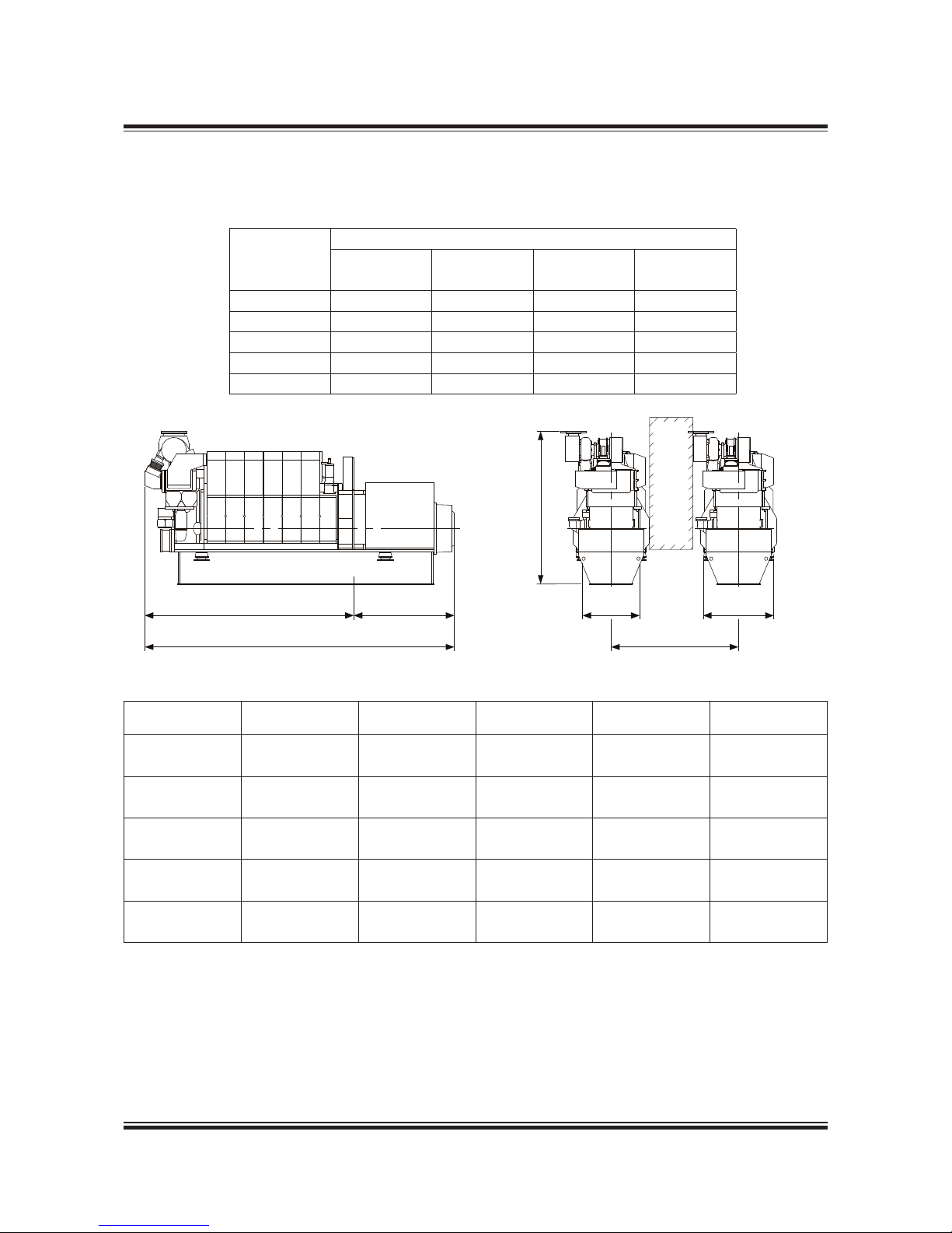
MAN Diesel 4.07
Page 1 of 2
MAN Diesel
198 82 816 .0MAN B& W 80-26MC/M C-C/ME/M E-C/ME-B/-G I-TII engin es
L21/31-Tll GenSet Data
Bore: 210 mm Stroke: 310 mm
Power layout
900 r/min 60 Hz 1,000 r/min 50 Hz
Eng. kW Gen. kW Eng. kW Gen. kW
5L21/31 1,000 950 1,000 950
6L21/31 1,320 1,254 1,320 1,254
7L21/31 1,540 1,463 1,540 1,463
8L21/31 1,760 1,672 1,760 1,672
9L21/31 1,980 1,881 1,980 1,881
178 23 043.2
Fig. 4.07.01: Power and outline of L21/31, IMO Tier II
0
(
1
!"
#
P Free passage between the engines, width 600 mm and height 2,000 mm.
Q Min. distance between engines: 2,400 mm (without gallery) and 2,600 mm (with galley)
* Depending on alternator
** Weight incl. standard alternator (based on a Uljanik alternator)
All dimensions and masses are approximate, and subject to changes without prior notice.
Cyl. no A (mm) * B (mm) * C (mm) H (mm)
**Dry weight
GenSet (t)
5 (900 rpm) 3,959 1,870 5,829 3,183 21.5
5 (1000 rpm) 3,959 1,870 5,829 3,183 21.5
6 (900 rpm) 4,314 2,000 6,314 3,183 23.7
6 (1000 rpm) 4,314 2,000 6,314 3,183 23.7
7 (900 rpm) 4,669 1,970 6,639 3,289 25.9
7 (1000 rpm) 4,669 1,970 6,639 3,289 25.9
8 (900 rpm) 5,024 2,250 7,274 3,289 28.5
8 (1000 rpm) 5,024 2,250 7,274 3,289 28.5
9 (900 rpm) 5,379 2,400 7,779 3,289 30.9
9 (1000 rpm) 5,379 2,400 7,779 3,289 30.9
Page 90

MAN Diesel 4.07
Page 2 of 2
MAN Diesel
198 82 816 .0MAN B& W 80-26MC/M C-C/ME/M E-C/ME-B/-G I-TII engin es
Fig. 4.07.02a: List of capacities for L21/31, 900 rpm, IMO Tier II
L21/31-Tll GenSet Data
1) LT cooling water flow first through LT stage charge air cooler, then
through lube oil cooler, water temperature outlet engine regulated by
mechanical thermostat
2) HT cooling water flow irst through water jacket and cylinder head, then
trough HT stage charge air cooler, water temperature outlet engine
regulated by mechanical thermostat
3) Tolerance: + 10% for rating coolers, - 15% for heat recovery
4) Basic values for layout of the coolers
5) under above mentioned reference conditions
6) Tolerance: quantity +/- 5%, temperature +/- 20°C
7) under below mentioned temperature at turbine outlet and pressure
according above mentioned reference conditions
8) Tolerance of the pumps delivery capacities must be considered by the
manufactures
5L:200 kW/cyl., 6L-9L: 220 kW/Cyl. at 1,000 rpm
Reference Condition: Tropic
Air temperature
LT-water temperature inlet engine (from system)
Air pressure
Relative humidity
°C
°C
bar
%
45
38
1
50
Temperature basis
Setpoint HT cooling water engine outlet
1)
Setpoint LT cooling water engine outlet
2)
Setpoint Lube oil inlet engine
°C
°C
°C
79 nominal (Range of mechanical thermostatic element 77 to 85)
35 nominal (Range of mechanical thermostatic element 29 to 41)
66 nominal (Range of mechanical thermostatic element 63 to 72)
Number of Cylinders - 56789
Engine output
Speed
kW
rpm
1,000 1,320 1,540 1,760 1,980
1,000
Heat to be dissipated
3)
Cooling water (C.W.) Cylinder
Charge air cooler; cooling water HT
Charge air cooler; cooling water LT
Lube oil (L.O.) cooler
Heat radiation engine
kW
kW
kW
kW
kW
176 233 272 310 349
294 370 418 462 504
163 205 232 258 284
180 237 277 316 356
56 74 86 98 110
Flow rates
4)
Internal (inside engine)
HT circuit (cylinder + charge air cooler HT stage)
LT circuit (lube oil + charge air cooler LT stage)
Lube oil
External (from engine to system)
HT water flow (at 40°C inlet)
LT water flow (at 38°C inlet)
m3/h
m3/h
m3/h
m3/h
m3/h
61 61 61 61 61
61 61 61 61 61
34 34 46 46 46
10.7 13.5 15.4 17.1 18.8
61 61 61 61 61
Air data
Temperature of charge air at charge air cooler outlet
Air flow rate
Charge air pressure
Air required to dissipate heat radiation (engine) (t
2-t1
=10°C)
°C
m3/h
5)
kg/kWh
bar
m3/h
49 52 54 55 56
6,548 8,644 10,084 11,525 12,965
7.17 7.17 7.17 7.17 7.17
4.13
17,980 23,800 27,600 31,500 35,300
Exhaust gas data
6)
Volume flow (temperature turbocharger outlet)
Mass flow
Temperature at turbine outlet
Heat content (190°C)
Permissible exhaust back pressure
m3/h
7)
t/h
°C
kW
mbar
13,162 17,324 20,360 23,217 26,075
7.4 9.7 11.4 13.0 14.6
349 349 349 349 349
352 463 544 620 696
< 30
Pumps
a) Engine driven pumps
HT circuit cooling water (2.5 bar)
LT circuit cooling water (2.5 bar)
Lube oil (4.5 bar)
b) External pumps
8)
Fuel oil feed pump (4 bar)
Fuel booster pump (8 bar)
m3/h
m3/h
m3/h
m3/h
m3/h
61 61 61 61 61
61 61 61 61 61
34 34 46 46 46
0.30 0.39 0.46 0.52 0.59
0.89 1.18 1.37 1.57 1.76
Starting air data
Air consumption per start, incl. air for jet assist (TDI) Nm
3
1.0 1.2 1.4 1.6 1.8
Page 91
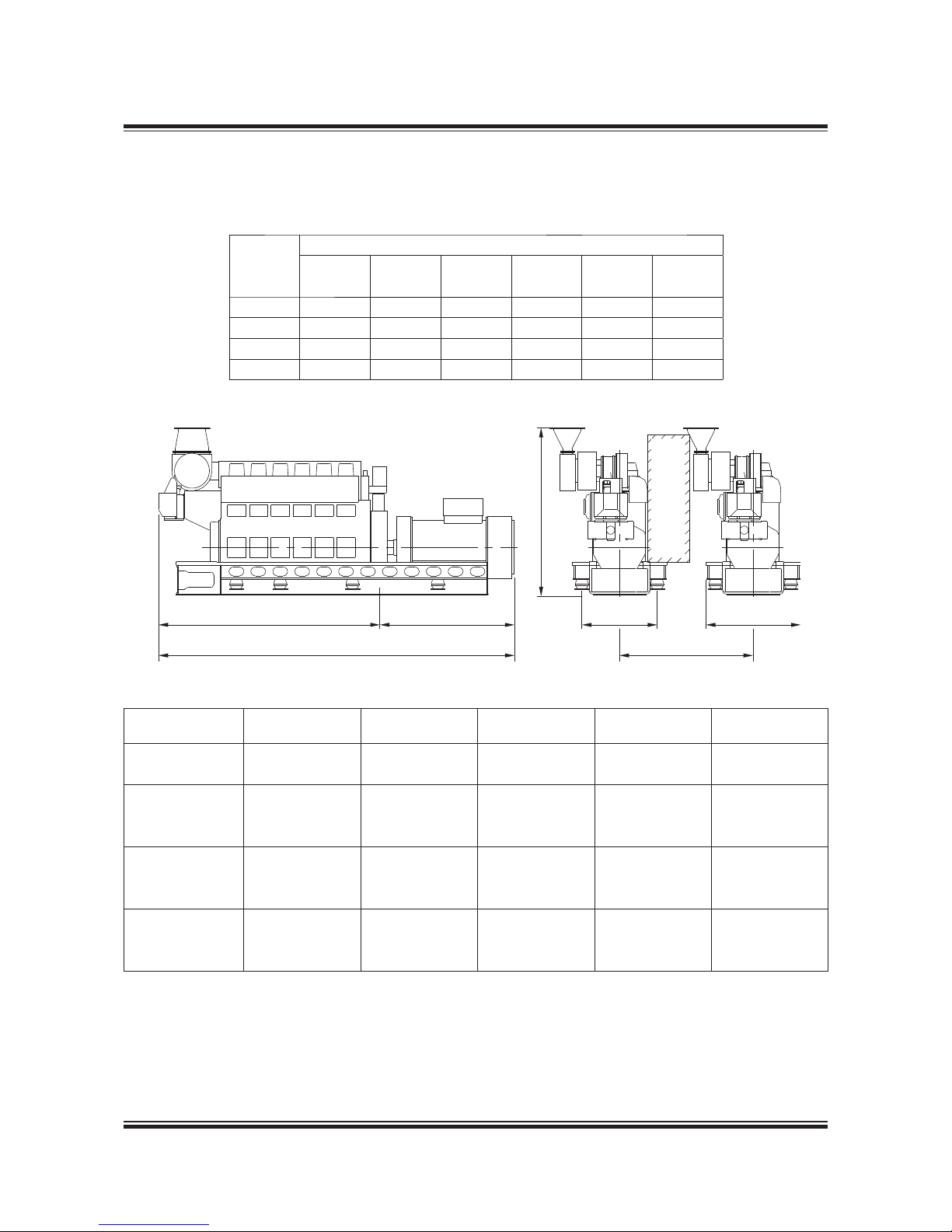
MAN Diesel 4.08
Page 1 of 3
MAN Diesel
198 82 828.0MA N B&W 80-26MC /MC-C/ME /ME-C/ME-B /-GI-TII engines
178 34 537.1
P Free passage between the engines, width 600 mm and height 2,000 mm
Q Min. distance between engines: 2,250 mm
* Depending on alternator
** Weight includes a standard alternator, make A. van Kaick
All dimensions and masses are approximate and subject to change without prior notice.
Fig. 4.08.01: Power and outline of L23/30H, IMO Tier II
A
C
B
H
1,270
Q
1,600
P
L23/30H-Tll GenSet Data
Bore: 225 mm Stroke: 300 mm
Power layout
720 r/min 60 Hz 750 r/min 50 Hz 900 r/min 60 Hz
Eng. kW Gen. kW Eng. kW Gen. kW Eng. kW Gen. kW
5L23/30H 650 620 675 640
6L23/30H 780 740 810 770 960 910
7L23/30H 910 865 945 900 1,120 1,065
8L23/30H 1,040 990 1,080 1,025 1,280 1,215
178 23 067.0
No. of Cyls. A (mm) * B (mm) * C (mm) H (mm)
**Dry weight
GenSet (t)
5 (720 r/min) 3,369 2,155 5,524 2,383 18.0
5 (750 r/min) 3,369 2,155 5,524 2,383 18.0
6 (720 r/min) 3,738 2,265 6,004 2,383 19.7
6 (750 r/min) 3,738 2,265 6,004 2,383 19.7
6 (900 r/min) 3,738 2,265 6,004 2,815 21.0
7 (720 r/min) 4,109 2,395 6,504 2,815 21.4
7 (750 r/min) 4,109 2,395 6,504 2,815 21.4
7 (900 r/min) 4,109 2,395 6,504 2,815 22.8
8 (720 r/min) 4,475 2,480 6,959 2,815 23.5
8 (750 r/min) 4,475 2,480 6,959 2,815 23.5
8 (900 r/min) 4,475 2,340 6,815 2,815 24.5
Page 92

MAN Diesel 4.08
Page 2 of 3
MAN Diesel
198 82 828.0MA N B&W 80-26MC /MC-C/ME /ME-C/ME-B /-GI-TII engines
Fig. 4.08.02a: List of capacities for L23/30H, 720/750 rpm, IMO Tier II
1) Tolerance: + 10% for rating coolers, - 15% for heat recovery
2) LT cooling water flow parallel through 1 stage charge air cooler and
through lube oil cooler and HT cooling water flow only through water
jacket and cylinder head, water temperature outlet engine regulated by
thermostat
3) Basic values for layout of the coolers
4) Under above mentioned reference conditions
5) Tolerance: quantity +/- 5%, temperature +/- 20°C
6) Under below mentioned temperature at turbine outlet and pressure
according above mentioned reference conditions
7) Tolerance of the pumps delivery capacities must be considered by the
manufactures
8)
To compensate for built on pumps, ambient condition, calorific value
and adequate circulations flow. The ISO fuel oil consumption is multiplied by 1.45.
5-8L23/30H: 130 kW/Cyl., 720 rpm or 135 kWCyl., 750 rpm
Reference Condition : Tropic
Air temperature
LT-water temperature inlet engine (from system)
Air pressure
Relative humidity
°C
°C
bar
%
45
36
1
50
Temperature basis
Setpoint HT cooling water engine outlet
Setpoint Lube oil inlet engine
°C
°C
82°C (engine equipped with HT thermostatic valve)
60°C (SAE30), 66°C (SAE40)
Number of Cylinders
-
5678
Engine output
Speed
kW
rpm
650 / 675 780 / 810 910 / 945 1,040 / 1,080
720 / 750
Heat to be dissipated
1)
Cooling water (C.W.) Cylinder
Charge air cooler; cooling water HT
Charge air cooler; cooling water LT
Lube oil (L.O.) cooler
Heat radiation engine
kW
kW
kW
kW
kW
182 219 257 294
1 stage cooler: no HT-stage
251 299 348 395
69 84 98 112
27 33 38 44
Air data
Temperature of charge air at charge air cooler outlet, max.
Air flow rate
Charge air pressure
Air required to dissipate heat radiation (engine) (t
2-t1
=10°C)
°C
m3/h
4)
kg/kWh
bar
m3/h
55 55 55 55
4,556 5,467 6,378 7,289
7.39 7.39 7.39 7.39
3.08
8,749 10,693 12,313 14,257
Exhaust gas data
5)
Volume flow (temperature turbocharger outlet)
Mass flow
Temperature at turbine outlet
Heat content (190°C)
Permissible exhaust back pressure
m3/h
6)
t/h
°C
kW
mbar
9,047 10,856 12,666 14,475
5.1 6.1 7.2 8.2
342 342 342 342
234 280 327 374
< 30
Pumps
a) Engine driven pumps
Fuel oil feed pump (5.5-7.5 bar)
HT cooling water pump (1-2.5 bar)
LT cooling water pump (1-2.5 bar)
Lube oil (3-5 bar)
b) External pumps
7)
Diesel oil pump (4 bar at fuel oil inlet A1)
Fuel oil supply pump 8) (4 bar discharge pressur)
Fuel oil circulating pump (8 bar at fuel oil inlet A1)
m3/h
m3/h
m3/h
m3/h
m3/h
m3/h
m3/h
1.0
36
55
16 16 20 20
0.48 0.57 0.67 0.76
0.23 0.28 0.32 0.37
0.48 0.57 0.67 0.76
Cooling water pumps for for "Internal Cooling Water System 1"
+ LT cooling water pump (1-2.5 bar) m
3
/h 35 42 48 55
Cooling water pumps for for "Internal Cooling Water System 2"
HT cooling water pump (1-2.5 bar)
+ LT cooling water pump (1-2.5 bar)
Lube oil pump (3-5 bar)
m
3
/h
m3/h
m3/h
20 24 28 32
35 42 48 55
14 15 16 17
Starting air system
Air consuption per start Nm
3
2.0 2.0 2.0 2.0
Nozzle cooling data
Nozzle cooling data m
3
/h 0.66
L23/30H-Tll GenSet Data
Page 93

MAN Diesel 4.08
Page 3 of 3
MAN Diesel
198 82 828.0MA N B&W 80-26MC /MC-C/ME /ME-C/ME-B /-GI-TII engines
Fig. 4.08.02b: List of capacities for L23/30H, 900 rpm, IMO Tier II
1) Tolerance: +10% for rating coolers, - 15% for heat recovery
2) LT cooling water flow parallel through 1 stage charge air cooler and
through lube oil cooler and HT cooling water flow only through water
jacket and cylinder head, water temperature outlet engine regulated by
thermostat
3) Basic values for layout of the coolers
4) Under above mentioned reference conditions
5) Tolerance: quantity +/- 5%, temperature +/- 20°C
6) Under below mentioned temperature at turbine outlet and pressure
according above mentioned reference conditions
7) Tolerance of the pumps delivery capacities must be considered by the
manufactures
8) To compensate for built on pumps, ambient condition, calorific value
and adequate circulations flow. The ISO fuel oil consumption is multiplied by 1.45.
6-8L23/30H: 160 kW/Cyl., 900 rpm
Reference Condition: Tropic
Air temperature
LT-water temperature inlet engine (from system)
Air pressure
Relative humidity
°C
°C
bar
%
45
36
1
50
Temperature basis
Setpoint HT cooling water engine outlet
Setpoint Lube oil inlet engine
°C
°C
82°C (engine equipped with HT thermostatic valve)
60°C (SAE30), 66°C (SAE40)
Number of Cylinders
-
678
Engine output
Speed
kW
rpm
960 1,120 1,280
900
Heat to be dissipated
1)
Cooling water (C.W.) Cylinder
Charge air cooler; cooling water HT
Charge air cooler; cooling water LT
Lube oil (L.O.) cooler
Heat radiation engine
kW
kW
kW
kW
kW
244 285 326
- 1 stage cooler: no HT-stage -
369 428 487
117 137 158
32 37 43
Air data
Temperature of charge air at charge air cooler outlet, max.
Air flow rate
Charge air pressure
Air required to dissipate heat radiation (engine) (t
2-t1
=10°C)
°C
m3/h
4)
kg/kWh
bar
m3/h
55 55 55
6,725 7,845 8,966
7,67 7,67 7,67
3.1
10,369 11,989 13,933
Exhaust gas data
5)
Volume flow (temperature turbocharger outlet)
Mass flow
Temperature at turbine outlet
Heat content (190°C)
Permissible exhaust back pressure
m3/h
6)
t/h
°C
kW
mbar
13,970 16,299 18,627
7.6 8.8 10.1
371 371 371
410 479 547
< 30
Pumps
a) Engine driven pumps
Fuel oil feed pump (5.5-7.5 bar)
HT cooling water pump (1-2.5 bar)
LT cooling water pump (1-2.5 bar)
Lube oil (3-5 bar)
b) External pumps
7)
Diesel oil pump (4 bar at fuel oil inlet A1)
Fuel oil supply pump (4 bar discharge pressur)
Fuel oil circulating pump (8 bar at fuel oil inlet A1)
m3/h
m3/h
m3/h
m3/h
m3/h
m3/h
m3/h
1.3
45
69
20 20 20
0.68 0.79 0.90
0.33 0.38 0.44
0.68 0.79 0.90
Cooling water pumps for for "Internal Cooling Water System 1"
+ LT cooling water pump (1-2.5 bar) m
3
/h 52 61 70
Cooling water pumps for for "Internal Cooling Water System 2"
HT cooling water pump (1-2.5 bar)
+ LT cooling water pump (1-2.5 bar)
Lube oil pump (3-5 bar)
m
3
/h
m3/h
m3/h
30 35 40
52 61 70
17 18 19
Starting air system
Air consuption per start Nm
3
2.0 2.0 2.0
Nozzle cooling data
Nozzle cooling data m
3
/h 0.66
L23/30H-Tll GenSet Data
Page 94
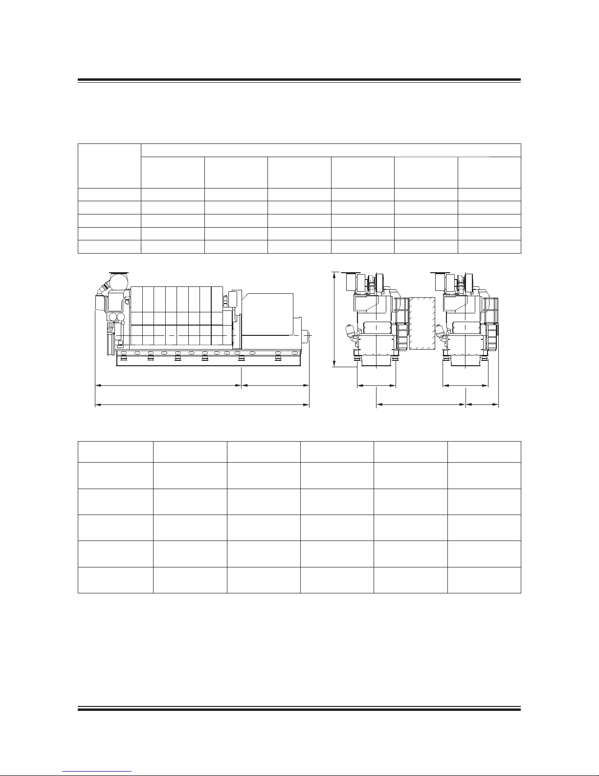
MAN Diesel
198 82 84 1.0MAN B&W 98-50MC/MC-C/ME/ME-C/ME-B/-GI-TII,
46-35ME-B/-GI-TII engines
MAN Diesel 4.09
Page 1 of 3
L27/38-Tll GenSet Data
Bore: 270 mm Stroke: 380 mm
Power layout
720 r/min 60 Hz 750 r/min 50 Hz
720/750 r/min
(MGO/MDO)
60/50 Hz
(MGO/MDO)
Eng. kW Gen. kW Eng. kW Gen. kW Eng. kW Gen. kW
5L27/38 1,500 1,440 1,600 1,536 - -
6L27/38 1,980 1,900 1,980 1,900 2,100 2,016
7L27/38 2,310 2,218 2,310 2,218 2,450 2,352
8L27/38 2,640 2,534 2,640 2,534 2,800 2,688
9L27/38 2,970 2,851 2,970 2,851 3,150 3,024
178 23 079.1
No. of Cyls. A (mm) * B (mm) * C (mm) H (mm)
**Dry weight
GenSet (t)
5 (720 r/min) 4,346 2,486 6,832 3,712 42.3
5 (750 r/min) 4,346 2,486 6,832 3,712 42.3
6 (720 r/min) 4,791 2,766 7,557 3,712 45.8
6 (750 r/min) 4,791 2,766 7,557 3,712 46.1
7 (720 r/min) 5,236 2,766 8,002 3,899 52.1
7 (750 r/min) 5,236 2,766 8,002 3,899 52.1
8 (720 r/min) 5,681 2,986 8,667 3,899 56.3
8 (750 r/min) 5,681 2,986 8,667 3,899 58.3
9 (720 r/min) 6,126 2,986 9,112 3,899 63.9
9 (750 r/min) 6,126 2,986 9,112 3,899 63.9
Fig. 4.09.01: Power and outline of L27/38, IMO Tier II
P Free passage between the engines, width 600 mm and height 2,000 mm
Q Min. distance between engines: 2,900 mm (without gallery) and 3,100 mm (with gallery)
* Depending on alternator
** Weight includes a standard alternator
All dimensions and masses are approximate and subject to change without prior notice.
178 33 898.3
A
C
B
H
1,480
P
Q
1,770
1,285
Page 95

MAN Diesel
198 82 84 1.0
MAN Diesel 4.09
Page 2 of 3
6-9L27/38: 350 kW/cyl., 720 rpm, MGO
Reference Condition: Tropic
Air temperature
LT-water temperature inlet engine (from system)
Air pressure
Relative humidity
°C
°C
bar
%
45
38
1
50
Temperature basis
Setpoint HT cooling water engine outlet
1)
Setpoint LT cooling water engine outlet
2)
Setpoint Lube oil inlet engine
°C
°C
°C
79 nominal (Range of mechanical thermostatic element 77 to 85)
35 nominal (Range of mechanical thermostatic element 29 to 41)
66 nominal (Range of mechanical thermostatic element 63 to 72)
Number of Cylinders - 6 7 8 9
Engine output
Speed
kW
rpm
2,100 2,450 2,800 3,150
720
Heat to be dissipated
3)
Cooling water (C.W.) Cylinder
Charge air cooler; cooling water HT
Charge air cooler; cooling water LT
Lube oil (L.O.) cooler
Heat radiation engine
kW
kW
kW
kW
kW
315 368 421 473
668 784 903 1,022
175 200 224 247
282 329 376 423
70 81 93 104
Flow rates
4)
Internal (inside engine)
HT circuit (cylinder + charge air cooler HT stage)
LT circuit (lube oil + charge air cooler LT stage)
Lube oil
External (from engine to system)
HT water flow (at 40°C inlet)
LT water flow (at 38°C inlet)
m3/h
m3/h
m3/h
m3/h
m3/h
58 58 58 58
58 58 58 58
64 92 92 92
21.5 24.8 28.1 31.4
58 58 58 58
Air data
Temperature of charge air at charge air cooler outlet
Air flow rate
Charge air pressure
Air required to dissipate heat radiation (engine) (t
2-t1
= 10°C)
°C
m3/h
5)
kg/kWh
bar
m3/h
50 53 55 56
12,792 14,924 17,056 19,188
6.67 6.67 6.67 6.67
4.01
22,682 26,247 30,135 33,699
Exhaust gas data
6)
Volume flow (temperature turbocharger outlet)
Mass flow
Temperature at turbine outlet
Heat content (190°C)
Permissible exhaust back pressure
m3/h
7)
t/h
°C
kW
mbar
27,381 31,944 36,508 41,071
14.4 16.8 19.2 21.6
388 388 388 388
857 1,000 1,143 1,285
< 30
Pumps
a) Engine driven pumps
HT circuit cooling water (2.5 bar)
LT circuit cooling water (2.5 bar)
Lube oil (4.5 bar)
b) External pumps
8)
Diesel oil pump (5 bar at fuel oil inlet A1)
Fuel oil supply pump (4 bar discharge pressure)
Fuel oil circulating pump (8 bar at fuel oil inlet A1)
m
3
/h
m
3
/h
m3/h
m3/h
m3/h
m3/h
58 58 58 58
58 58 58 58
64 92 92 92
1.48 1.73 1.98 2.23
0.71 0.83 0.95 1.07
1.48 1.73 1.98 2.23
Starting air data
Air consumption per start, incl. air for jet assist (IR/TDI) Nm
3
2.9 3.3 3.8 4.3
1) LT cooling water flow first through LT stage charge air cooler, then
through lube oil cooler, water temperature outlet engine regulated by
mechanical thermostat.
2) HT cooling water flow first through HT stage charge air cooler, then
through water jacket and cylinder head, water temperature outlet engine regulated by mechanical thermostat.
3) Tolerance: + 10% for rating coolers, - 15% for heat recovery.
4) Basic values for layout of the coolers.
5) Under above mentioned reference conditions.
6) Tolerance: quantity +/- 5%, temperature +/- 20°C.
7) Under below mentioned temperature at turbine outlet and pressure
according above mentioned reference conditions.
8) Tolerance of the pumps delivery capacities must be considered by the
manufactures.
Fig. 4.09.02a: List of capacities for L27/38, 720 rpm, IMO Tier II
MAN B&W 98-50MC/MC-C/ME/ME-C/ME-B/-GI-TII,
46-35ME-B/-GI-TII engines
L27/38-Tll GenSet Data
Page 96

MAN Diesel
198 82 84 1.0MAN B&W 98-50MC/MC-C/ME/ME-C/ME-B/-GI-TII,
46-35ME-B/-GI-TII engines
MAN Diesel 4.09
Page 3 of 3
1) LT cooling water flow first through LT stage charge air cooler, then
through lube oil cooler, water temperature outlet engine regulated by
mechanical thermostat.
2) HT cooling water flow first through HT stage charge air cooler, then
through water jacket and cylinder head, water temperature outlet
engine regulated by mechanical thermostat.
3) Tolerance: + 10% for rating coolers, - 15% for heat recovery.
4) Basic values for layout of the coolers.
5) Under above mentioned reference conditions.
6) Tolerance: quantity +/- 5%, temperature +/- 20°C.
7) Under below mentioned temperature at turbine outlet and pressure
according above mentioned reference conditions.
8) Tolerance of the pumps delivery capacities must be considered by the
manufactures.
6-9L27/38: 350 kW/cyl., 750 rpm, MGO
Reference Condition : Tropic
Air temperature
LT-water temperature inlet engine (from system)
Air pressure
Relative humidity
°C
°C
bar
%
45
38
1
50
Temperature basis
Setpoint HT cooling water engine outlet
1)
Setpoint LT cooling water engine outlet
2)
Setpoint Lube oil inlet engine
°C
°C
°C
79 nominal (Range of mechanical thermostatic element 77 to 85)
35 nominal (Range of mechanical thermostatic element 29 to 41)
66 nominal (Range of mechanical thermostatic element 63 to 72)
Number of Cylinders - 6 7 8 9
Engine output
Speed
kW
rpm
2,100 2,450 2,800 3,150
750
Heat to be dissipated
3)
Cooling water (C.W.) Cylinder
Charge air cooler; cooling water HT
Charge air cooler; cooling water LT
Lube oil (L.O.) cooler
Heat radiation engine
kW
kW
kW
kW
kW
315 368 421 473
679 797 916 1037
181 208 234 258
282 329 376 423
70 81 93 104
Flow rates
4)
Internal (inside engine)
HT circuit (cylinder + charge air cooler HT stage)
LT circuit (lube oil + charge air cooler LT stage)
Lube oil
External (from engine to system)
HT water flow (at 40°C inlet)
LT water flow (at 38°C inlet)
m3/h
m3/h
m3/h
m3/h
m3/h
69 69 69 69
69 69 69 69
66 96 96 96
21.9 25.4 28.9 32.2
69 69 69 69
Air data
Temperature of charge air at charge air cooler outlet
Air flow rate
Charge air pressure
Air required to dissipate heat radiation (engine) (t
2-t1
=10°C)
°C
m3/h 5)
kg/kWh
bar
m3/h
55 55 55 55
13,003 15,170 17,338 19,505
6.78 6.78 6.78 6.78
4.09
22,682 26,247 30,135 33,699
Exhaust gas data
6)
Volume flow (temperature turbocharger outlet)
Mass flow
Temperature at turbine outlet
Heat content (190°C)
Permissible exhaust back pressure
m3/h 7)
t/h
°C
kW
mbar
27,567 32,161 36,756 41,350
14.7 17.1 19.5 22.0
382 382 382 382
844 985 1,126 1,266
< 30
Pumps
a) Engine driven pumps
HT circuit cooling water (2.5 bar)
LT circuit cooling water (2.5 bar)
Lube oil (4.5 bar)
b) External pumps
8)
Diesel oil pump (5 bar at fuel oil inlet A1)
Fuel oil supply pump (4 bar discharge pressure)
Fuel oil circulating pump (8 bar at fuel oil inlet A1)
m3/h
m3/h
m3/h
m3/h
m3/h
m3/h
69 69 69 69
69 69 69 69
66 96 96 96
1.48 1.73 1.98 2.23
0.71 0.83 0.95 1.07
1.48 1.73 1.98 2.23
Starting air data
Air consumption per start, incl. air for jet assist (IR/TDI) Nm
3
2.9 3.3 3.8 4.3
Fig. 4.09.02b: List of capacities for L27/38, 750 rpm, IMO Tier II
L27/38-Tll GenSet Data
Page 97
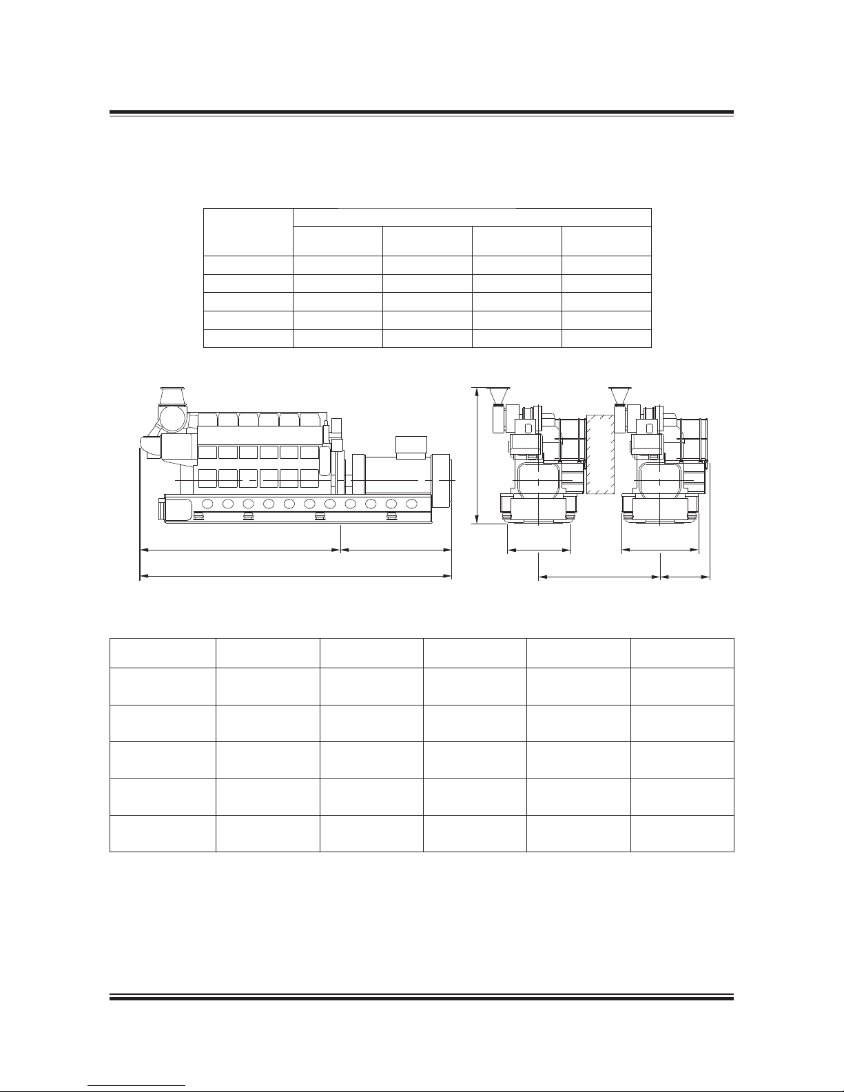
MAN Diesel 4.10
Page 1 of 3
MAN Diesel
198 82 85 3.0MAN B&W 98-50MC/MC-C/ME/ME-C/ME-B/-GI-TII,
46-35ME-B/-GI-TII engines
L28/32H-Tll GenSet Data
Bore: 280 mm Stroke: 320 mm
Power layout
720 r/min 60 Hz 750 r/min 50 Hz
Eng. kW Gen. kW Eng. kW Gen. kW
5L28/32H 1,050 1,000 1,100 1,045
6L28/32H 1,260 1,200 1,320 1,255
7L28/32H 1,470 1,400 1,540 1,465
8L28/32H 1,680 1,600 1,760 1,670
9L28/32H 1,890 1,800 1,980 1,880
178 23 092.0
No. of Cyls. A (mm) * B (mm) * C (mm) H (mm)
**Dry weight
GenSet (t)
5 (720 r/min) 4,279 2,400 6,679 3,184 32.6
5 (750 r/min) 4,279 2,400 6,679 3,184 32.6
6 (720 r/min) 4,759 2,510 7,269 3,184 36.3
6 (750 r/min) 4,759 2,510 7,269 3,184 36.3
7 (720 r/min) 5,499 2,680 8,179 3,374 39.4
7 (750 r/min) 5,499 2,680 8,179 3,374 39.4
8 (720 r/min) 5,979 2,770 8,749 3,374 40.7
8 (750 r/min) 5,979 2,770 8,749 3,374 40.7
9 (720 r/min) 6,199 2,690 8,889 3,534 47.1
9 (750 r/min) 6,199 2,690 8,889 3,534 47.1
P Free passage between the engines, width 600 mm and height 2,000 mm
Q Min. distance between engines: 2,655 mm (without gallery) and 2,850 mm (with gallery)
* Depending on alternator
** Weight includes a standard alternator, make A. van Kaick
All dimensions and masses are approximate and subject to change without prior notice.
178 33 921.3
Fig. 4.10.01: Power and outline of L28/32H, IMO Tier II
A
C
B
HP
1,490
Q
1,800
1,126
Page 98

MAN Diesel 4.10
Page 2 of 3
MAN Diesel
198 82 85 3.0MAN B&W 98-50MC/MC-C/ME/ME-C/ME-B/-GI-TII,
46-35ME-B/-GI-TII engines
Fig. 4.10.02a: List of capacities for L28/32H, 750 rpm, IMO Tier II
L28/32H-Tll GenSet Data
1) Tolerance: + 10% for rating coolers, - 15% for heat recovery
2) Basic values for layout of the coolers
3) Under above mentioned reference conditions
4) Tolerance: quantity +/- 5%, temperature +/- 20°C
5) under below mentioned temperature at turbine outlet and pressure according above mentioned reference conditions
6) Tolerance of the pumps delivery capacities must be considered by the
manufactures
* Only valid for engines equipped with internal basic cooling water sys-
tem no. 1 and 2.
** Only valid for engines equipped with combined coolers, internal basic
cooling water system no. 3
5L-9L: 220 kW/Cyl. at 750 rpm
Reference Condition: Tropic
Air temperature
LT water temperature inlet engine (from system)
Air pressure
Relative humidity
°C
°C
bar
%
45
38
1
50
Number of Cylinders
-
56789
Engine output
Speed
kW
rpm
1,100 1,320 1,540 1,760 1,980
750
Heat to be dissipated
1)
Cooling water (C.W.) Cylinder
Charge air cooler; cooling water HT
Charge air cooler; cooling water LT
Lube oil (L.O.) cooler
Heat radiation engine
kW
kW
kW
kW
kW
245 294 343 392 442
0
(Single stage charge air cooler)
387 435 545 587 648
201 241 281 321 361
27 33 38 44 49
Flow rates
2)
Internal (inside engine)
HT cooling water cylinder
LT cooling water lube oil cooler *
LT cooling water lube oil cooler **
LT cooling water charge air cooler
m3/h
m3/h
m3/h
m3/h
37 45 50 55 60
7.8 9.4 11 12.7 14.4
28 28 40 40 40
37 45 55 65 75
Air data
Temperature of charge air at charge air cooler outlet
Air flow rate
Charge air pressure
Air required to dissipate heat radiation (engine) (t
2-t1
=10°C)
°C
m3/h
3)
kg/kWh
bar
m3/h
52 54 52 52 55
7,826 9,391 10,956 12,521 14,087
7.79 7.79 7.79 7.79 7.79
3.07
8,749 10,693 12,313 14,257 15,878
Exhaust gas data
4)
Volume flow (temperature turbocharger outlet)
Mass flow
Temperature at turbine outlet
Heat content (190°C)
Permissible exhaust back pressure
m3/h 5)
t/h
°C
kW
mbar
15,520 18,624 21,728 24,832 27,936
8.8 10.5 12.3 14.1 15.8
342 342 342 342 342
401 481 561 641 721
< 30
Pumps
a) Engine driven pumps
Fuel oil feed pump (5,5-7,5 bar)
HT circuit cooling water (1,0-2,5 bar)
LT circuit cooling water (1,0-2,5 bar)
Lube oil (3,0-5,0 bar)
b) External pumps
6)
Diesel oil pump (4 bar at fuel oil inlet A1)
Fuel oil supply pump (4 bar discharge pressure)
Fuel oil circulating pump (8 bar at fuel oil inlet A1)
HT circuit cooling water (1,0-2,5 bar)
LT circuit cooling water (1,0-2,5 bar) *
LT circuit cooling water (1,0-2,5 bar) **
Lube oil (3,0-5,0 bar)
m3/h
m3/h
m3/h
m3/h
m3/h
m3/h
m
3
/h
m
3
/h
m3/h
m3/h
m3/h
1.4 1.4 1.4 1.4 1.4
45 45 60 60 60
45 60 75 75 75
24 24 34 34 34
0.78 0.93 1.09 1.24 1.40
0.37 0.45 0.52 0.60 0.67
0.78 0.93 1.09 1.24 1.40
37 45 50 55 60
45 54 65 77 89
65 73 95 105 115
22 23 25 27 28
Page 99

MAN Diesel 4.10
Page 3 of 3
MAN Diesel
198 82 85 3.0MAN B&W 98-50MC/MC-C/ME/ME-C/ME-B/-GI-TII,
46-35ME-B/-GI-TII engines
Fig. 4.10.02b: List of capacities for L28/32H, 720 rpm, IMO Tier II.
L28/32H-Tll GenSet Data
1) Tolerance: + 10% for rating coolers, - 15% for heat recovery
2) Basic values for layout of the coolers
3) under above mentioned reference conditions
4) Tolerance: quantity +/- 5%, temperature +/- 20°C
5) Under below mentioned temperature at turbine outlet and pressure
according above mentioned reference conditions
6) Tolerance of the pumps delivery capacities must be considered by the
manufactures
* Only valid for engines equipped with internal basic cooling water sys-
tem no. 1 and 2.
** Only valid for engines equipped with combined coolers, internal basic
cooling water system no. 3
5L-9L: 210 kW/Cyl. at 720 rpm
Reference Condition: Tropic
Air temperature
LT water temperature inlet engine (from system)
Air pressure
Relative humidity
°C
°C
bar
%
45
38
1
50
Number of Cylinders
-
56789
Engine output
Speed
kW
rpm
1,050 1,260 1,470 1,680 1,890
720
Heat to be dissipated
1)
Cooling water (C.W.) Cylinder
Charge air cooler; cooling water HT
Charge air cooler; cooling water LT
Lube oil (L.O.) cooler
Heat radiation engine
kW
kW
kW
kW
kW
234 281 328 375 421
0
(Single stage charge air cooler)
355 397 500 553 592
191 230 268 306 345
26 31 36 42 47
Flow rates
2)
Internal (inside engine)
HT cooling water cylinder
LT cooling water lube oil cooler *
LT cooling water lube oil cooler **
LT cooling water charge air cooler
m3/h
m3/h
m3/h
m3/h
37 45 50 55 60
7.8 9.4 11 12.7 14.4
28 28 40 40 40
37 45 55 65 75
Air data
Temperature of charge air at charge air cooler outlet
Air flow rate
Charge air pressure
Air required to dissipate heat radiation (engine) (t
2-t1
=10°C)
°C
m3/h
3)
kg/kWh
bar
m3/h
51 52 51 52 53
7,355 8,826 10,297 11,768 13,239
7.67 7.67 7.67 7.67 7.67
2.97
8,425 10,045 11,665 13,609 15,230
Exhaust gas data
4)
Volume flow (temperature turbocharger outlet)
Mass flow
Temperature at turbine outlet
Heat content (190°C)
Permissible exhaust back pressure
m3/h
5)
t/h
°C
kW
mbar
14,711 17,653 20,595 23,537 26,479
8.3 9.9 11.6 13.2 14.9
347 347 347 347 347
389 467 545 623 701
< 30
Pumps
a) Engine driven pumps
Fuel oil feed pump (5,5-7,5 bar)
HT circuit cooling water (1,0-2,5 bar)
LT circuit cooling water (1,0-2,5 bar)
Lube oil (3,0-5,0 bar)
b) External pumps
6)
Diesel oil pump (4 bar at fuel oil inlet A1)
Fuel oil supply pump (4 bar discharge pressure)
Fuel oil circulating pump (8 bar at fuel oil inlet A1)
HT circuit cooling water (1,0-2,5 bar)
LT circuit cooling water (1,0-2,5 bar) *
LT circuit cooling water (1,0-2,5 bar) **
Lube oil (3,0-5,0 bar)
m3/h
m3/h
m3/h
m3/h
m3/h
m3/h
m
3
/h
m
3
/h
m3/h
m3/h
m3/h
1.4 1.4 1.4 1.4 1.4
45 45 60 60 60
45 60 75 75 75
24 24 34 34 34
0.74 0.89 1.04 1.19 1.34
0.36 0.43 0.50 0.57 0.64
0.74 0.89 1.04 1.19 1.34
37 45 50 55 60
45 54 65 77 89
65 73 95 105 115
22 23 25 27 28
Page 100

 Loading...