

Page 1
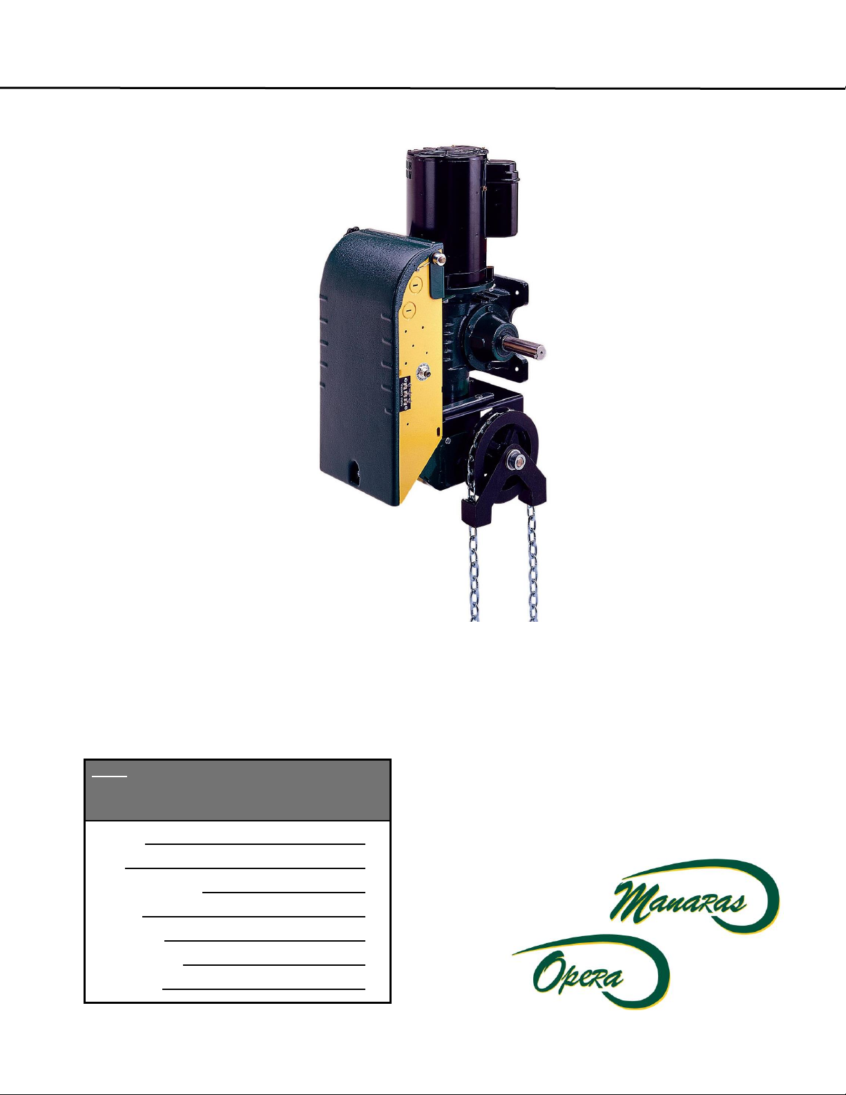
IInnssttaallllaattiioonn &
& IInnssttrruuccttiioonn
M
Maannuuaall
Note: Read this manual carefully before
installing the operator and place this installation
manual in an accessible place near the
operator. For future reference record:
Model #
Date
Wiring Diagram #
Serial #
Project No.
Project Name
Door No. #
O
O
p
p
e
err
a
a--
G
G
H
H
Page 2
2
IMPORTANT SAFETY INSTRUCTIONS
WARNING
TO REDUCE THE RISK OF SEVERE INJURY OR DEATH, READ AND FOLLOW ALL INSTRUCTIONS.
1. Never allow children to operate or play with or near door.
2. Check to see that the operator is correct for the type, size of door and frequency of use per the operator
specifications.
3. If the door system is near a residential area, or pedestrian traffic is expected near the door system,
additional equipment such as electric reversing edges, photocells, or similar devices must be installed as
part of the system to prevent entrapment.
4. Reversing devices appropriate to the application must be installed as part of the system.
5. Outdoor or easily accessible controls must be of the security type to prevent unauthorized use of the system.
6. Place controls far enough from the door so that a user cannot touch the door when operating the controls.
7. Controls should be placed so the user has full view of the door when operating.
8. Always keep moving door in sight and away from people or vehicles until it is completely opened or closed. NO
ONE SHOULD CROSS THE PATH OF THE MOVING DOOR.
9. If a person is trapped under the door, push the "OPEN" control button.
10. Do not overtighten a clutch to compensate for a damaged door.
11. Test door and service monthly. After adjusting the limit travel, retest the door opener. Failure to adjust the door
may cause death or injury.
12. KEEP DOORS PROPERLY BALANCED. See door owner's manual. An improperly balanced door could cause
severe injury. Have a qualified service person make repairs to cables, spring assemblies and other hardware.
13. If possible, use the emergency release only when the door is closed. Use caution when using this release with
the door open. Weak or broken springs may cause the door to fall rapidly, causing injury or death.
14. You are responsible for assuring that the owner of the door system understands its basic operation and safety.
In particular, be sure the owner/end-user understands the location and operation of the manual disconnect.
15. Point out to the owner/end-user of the door system that children or pets should not be allowed to play on or
near the door or any part of the system, and that the safety instructions supplied with this operator are the
responsibility of the owner/end-user.
16. Leave the installation and maintenance manual for this operator as well as any additional information supplied
with this operator or other components of the door system with the owner/end-user.
17. If you have any question about the safety of the door operating system, do not install the operator, contact us.
WARNING
DO NOT CONNECT POWER SUPPLY WHILE INSTALLING, SERVICING OR ADJUSTING THE
ELECTRIC MOTOR
WARNING
NOT APPLICABLE FOR RESIDENTIAL USE. ONLY FOR INDUSTRIAL AND COMMERCIAL
APPLICATIONS
Page 3

3
TABLE OF CONTENTS
Page
GENERAL PARTS & SPECIFICATIONS 4
WEIGHT AND DIMENSIONS 4
PRODUCT APPLICATION 5
DELIVERY OF OPERATOR 5
HARDWARE 5
INSTALLATION 6
HOIST-A-MATIC 10
CLUCTH ADJUSTMENT 12
BRAKE ADJUSTMENT 13
AIR BEARTHER AND LUBRICANT 15
SCHEDULED MAINTENANCE 17
Opera-GH EXPLODED VIEW 18
SPECIFIC TO ELECTRONIC CONTROL BOARD 19
Power, Control and Accessory Wiring 20
Program Setting 24
Mode Setting 25
Door Lock Sensor 26
Troubleshooting on ECB 27-28
Single phase Wiring Diagram 29
3-phase Wiring Diagram 30
RED & GREEN WARNING LIGHTS 31
Warning lights sequence 32
Programming of warning lights sequence 32
Connection of Red & Green lights 32
SPECIFIC TO HARDWIRED ELECTRIC CONTROL 33
Wiring of an Opera-GH 34-35
Accessory wiring 36
Troubleshooting on hardwiring circuit 40-41
Single phase Wiring Diagram 42
3-phase Wiring Diagram 43
WARRANTY POLICY 44
NOTES 45-47
Page 4
4
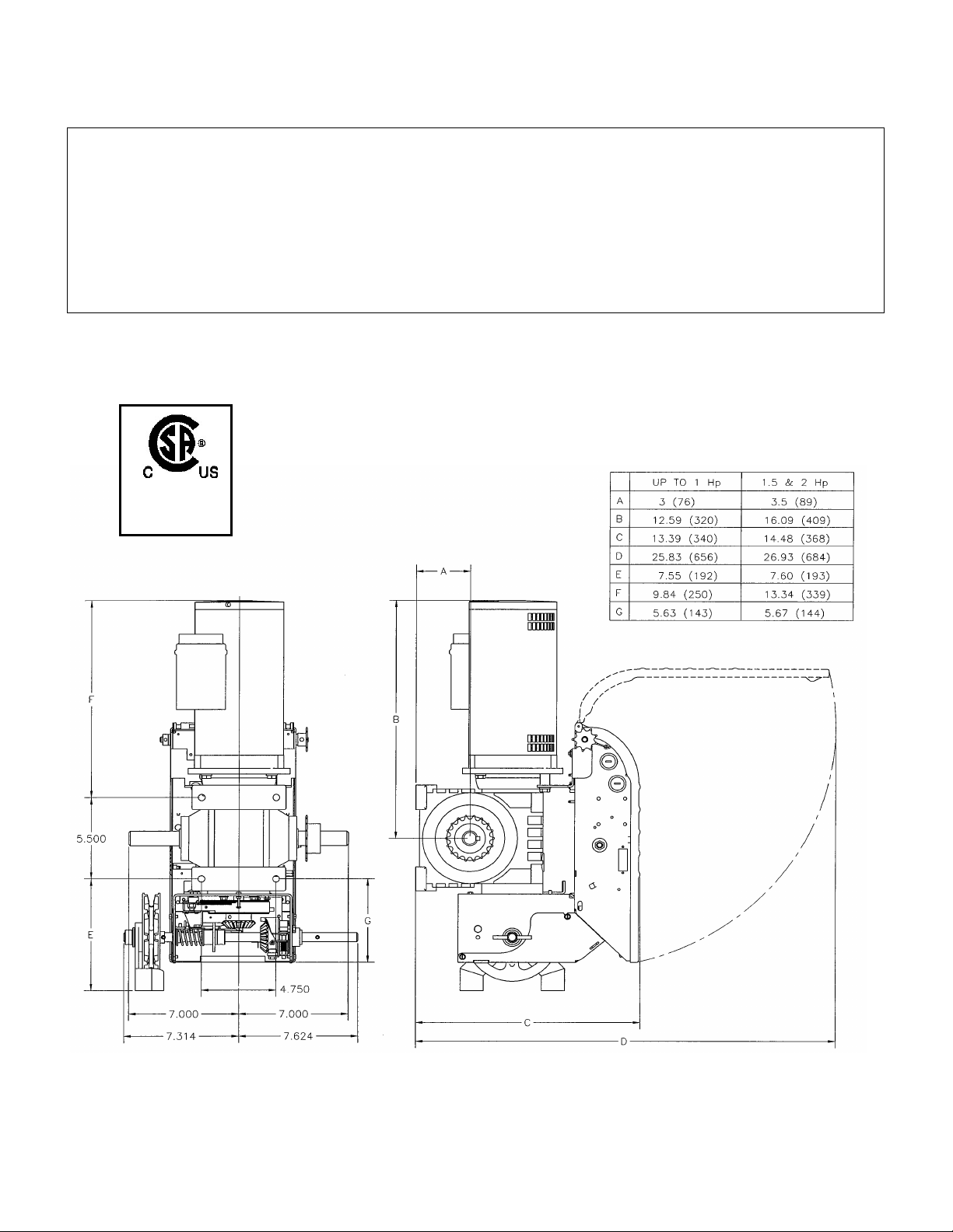
SPECIFICATIONS
GENERAL
SUPPLY VOLTAGE………………….. 115, 230 VAC single phase, 208, 460, 575 VAC three phase
CONTROL VOLTAGE………………. 24VAC class 2 transformer, 2 amp fuse type ACG
MOTOR …………………………………. Continuous duty
1/2, 3/4, 1, 1 ½, 2 Horsepower (2HP is not available in single phase)
OPERATOR OUTPUT SPEED……… 38 RPM
NET WEIGHT (Operator only)……… 78 Lbs (35 Kg) for 1/2HP 115V Opera-GH model
STANDARD WIRING TYPE………… C2-momentary contact to open and stop and
constant pressure to close.
DIMENSIONS
OGH
In compliance
with UL325
Page 5
5
Sticker to be placed next the
to the O/C/S button station
OPERA: HEAVY DUTY JACKSHAFT OPERATOR
IMPORTANT: UPON COMPLETION OF OPERATOR INSTALLATION THIS MANUAL MUST BE GIVEN
TO THE END-USER.
1. PRODUCT APPLICATION
The model Opera-GH heavy-duty jackshaft operator is designed for use on commercial or industrial doors
of all types provided that the door has a shaft as basic driving element (doors with high lift, vertical lift, rolling
doors and grilles). All Opera-GH door operators are designed and constructed in accordance with UL325
Standard, and certified by CSA Laboratories.
2. DELIVERY OF OPERATOR
Upon delivery of your heavy-duty jackshaft operator Opera-GH, inspect the unit immediately for shipping
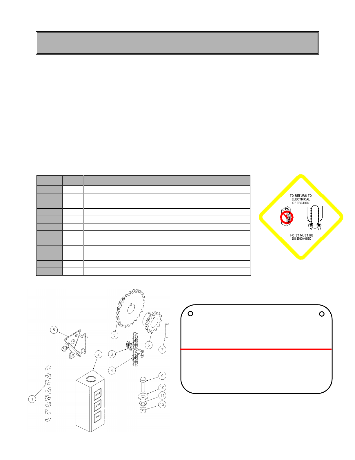
damage. Verify that you have received all the hardware parts mentioned in TABLE 1 and shown in Figure 1.
Other items may be present, such as radio controls or other types of optional equipment, if ordered. If any
item is missing or if there is evidence of damage, call the transport company first.
* Check to make sure that the available power supply to be connected to the operator is of the same voltage,
frequency, phase and amperage as indicated on the nameplate of the operator.
3. HARDWARE
TABLE 1 STANDARD PARTS LIST FOR OPERA JACKSHAFT OPERATOR
PART #
QTY
DESCRIPTION
1
1
Pocket wheel hand chain (2X door shaft less 4 ft. (1.2m)
2
1
3-button open/close/stop push-button station
3
1
#50 connecting link
4
1
#50 roller chain x 4'(1.2m) or x 5’ when sprocket is 42 teeth or more
5
1
** Sprocket 50B x " c/w set screws for door shaft
6
1
Sprocket 50B12 x 1,0 " c/w set screws for OPERATM output shaft
7
1
Square shaft key 1/4" x 1-1/2" L for OPERATM output shaft
8
1
Chain keeper for Opera-GH
9
4
3/8" x 1-1/4" bolts
10
4
3/8" washers
11
4
3/8" lock washers
12
4
3/8" nuts
** See SPECIFICATIONS, DOOR SPEED AND AVAILABLE DOOR ADJUSTMENT
Figure 1 Hardware and Danger Warning Tag
WARNING
TO PREVENT ENTRAPMENT,
DO NOT START DOOR DOWN UNLESS
DOORWAY IS CLEAR
AVERTISSEMENT
POUR ÉVITER TOUT COINCEMENT, NE
PAS ABAISSER LA PORTE TANT
QUE L’EMBRASURE N’EST PAS LIBRE.
Ensure that the Warning tag supplied with
the operator is properly fixed on the door
and it is visible while the door is moving
Page 6
6
4. INSTALLATION
All heavy-duty Opera-GH jackshaft operators are tested and adjusted at the factory. When installing your unit,
please note that the limit cams are resting in the center of the cam-shaft.
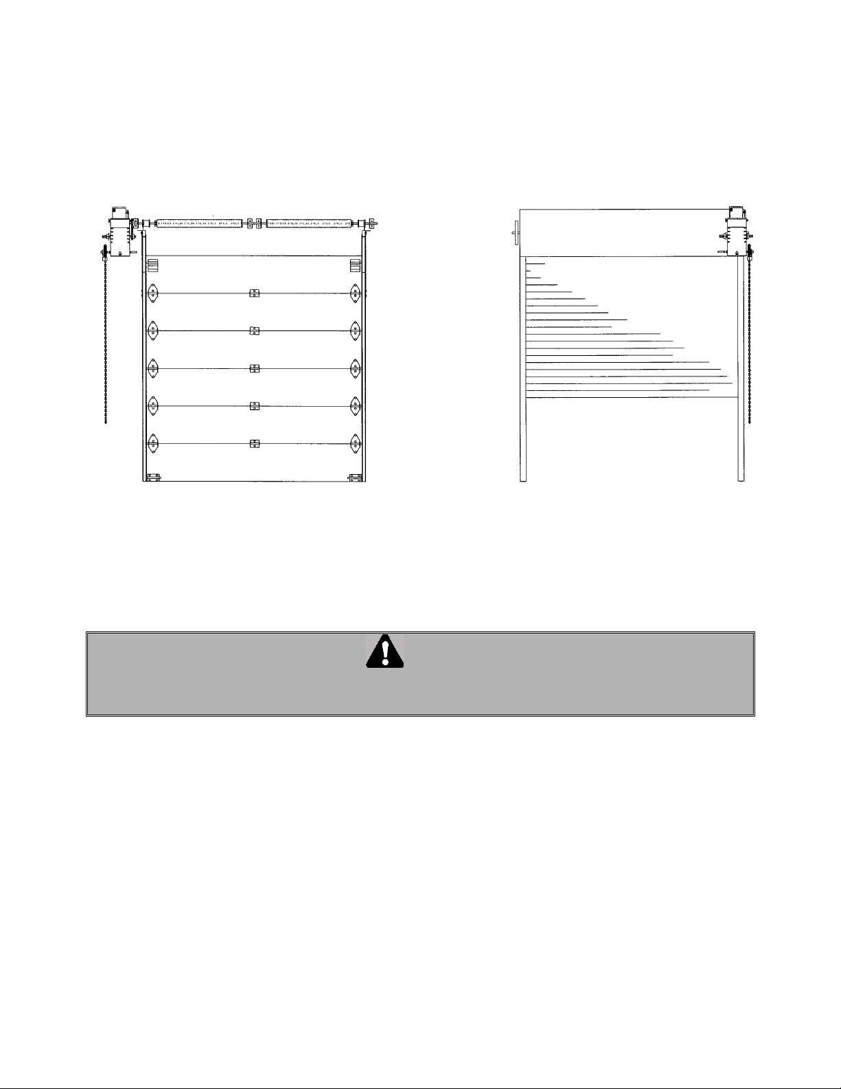
The Opera-GH operator has a dual output shaft and may be mounted on either the left or right hand side of a
sectional door (see Figure 2 and Figure 3). Place sprocket on either the right or the left end of the output shaft
according to the desired handing.
4.1 IMPORTANT INSTALLATION INSTRUCTIONS
WARNING
TO REDUCE THE RISK OF SEVERE INJURY OR DEATH, READ AND FOLLOW ALL INSTALLATION
INSTRUCTIONS.
1. Installation of this door operator must be done by a qualified installer.
2. Insure that the door is properly installed and works freely in both directions. Do not install the operator until all
door problems have been corrected. If necessary, oil all moving parts (chains, rollers, guides, etc.).
3. Remove all old accessories (locks, bolts, etc.) before installing door operator.
4. Do not connect the operator to a source of power until instructed to do so.
5. Locate control push-button station within sight of the door, at a minimum height of 5 ft. (1.5 m) so small
children cannot reach it, and away from all moving parts of the door.
Figure 2 Left side mount
Figure 3 Right side Hood Mount
Page 7
7
4.2 INSTALLATION OF Opera-GH OPERATOR
IMPORTANT NOTE: THIS OPERATOR MUST BE INSTALLED A MINIMUM OF 8 FT. (2.4 m) ABOVE FLOOR.
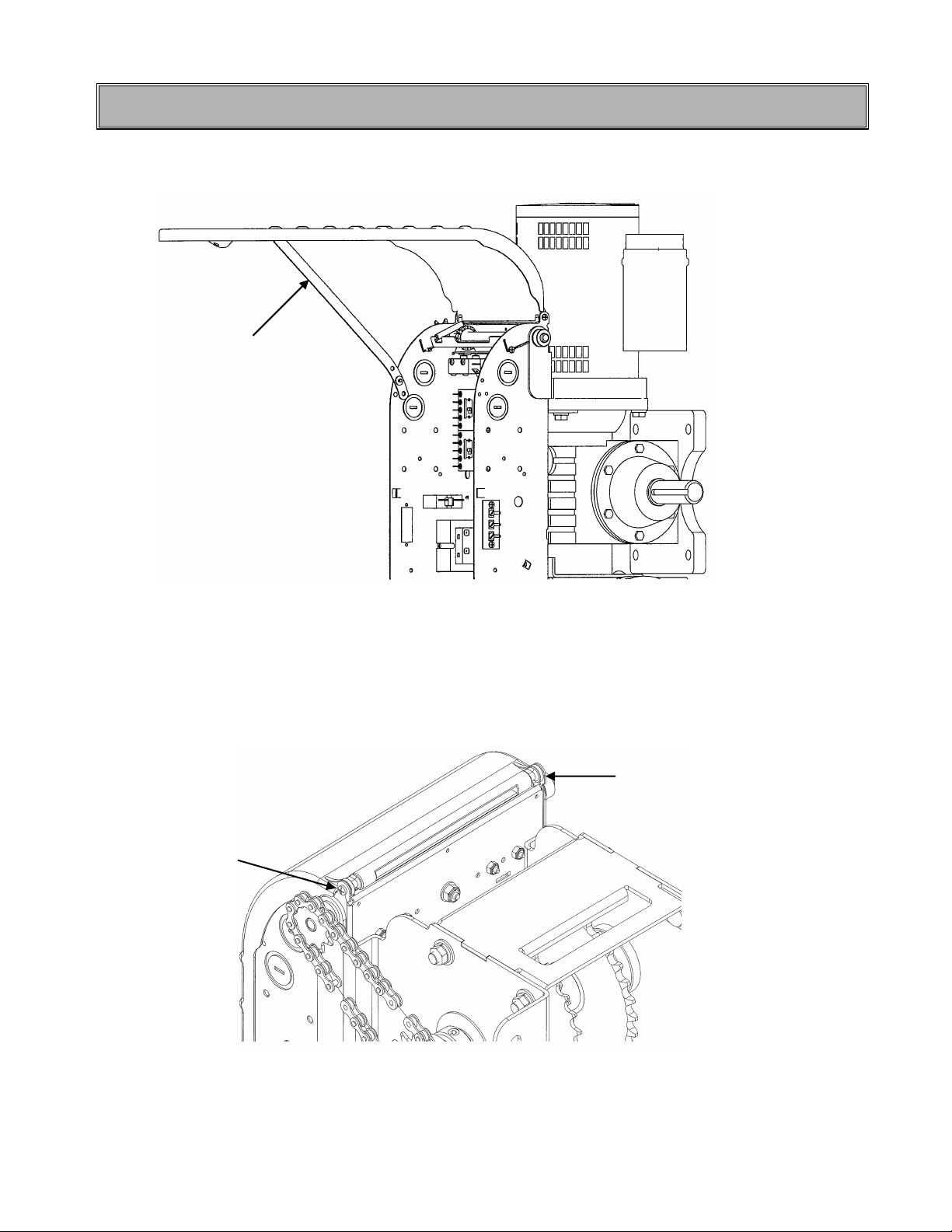
To open the control box cover, loosen the screw at the base of the cover. If the cover cannot be fully opened,
the retaining arm may be used to hold the cover in other positions.
Figure 4 Control box cover opening
After installation, verify that there is no obstacle in the way when opening the control box cover. If so, it is
possible to remove the cover by unscrewing it from the box before putting the operator on the wall or hood
(see Figure 5).
Figure 5 Unscrewing control box
Retaining arm
Remove the
screw
Remove the
screw
Page 8
8
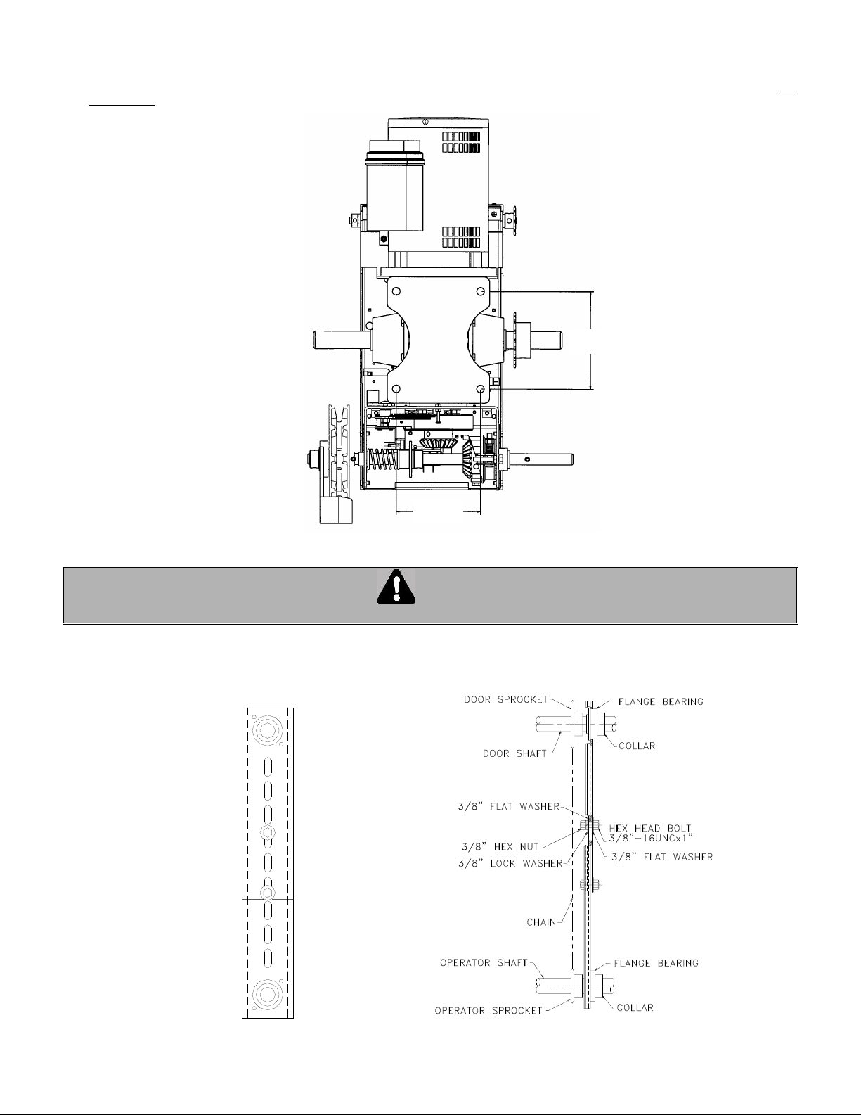
Locate the four mounting holes. The optimum distance between the door shaft and operator drive shaft is between
12" and 15". Mount the Opera-GH unit by fastening it to the wall, bench or hood with 3/8" or 1/2" thru-bolts or if the
wall is of such construction so as to prohibit use of thru-bolts, lag bolts and shields of sufficient size may be used. Do
not tighten.
Figure 6 Mounting dimensions for wall or hood
CAUTION
MAKE CERTAIN THAT OPERATOR IS PERFECTLY ALIGNED WITH DOOR SHAFT OTHERWISE DAMAGE CAN OCCUR
1. Place the driven sprocket on the door shaft loosely and align it with the drive sprocket of the operator.
NOTE: If a chain spreader has been ordered along with your operator, see Figure 7 and Figure 8 below
for installation.
Figure 7 Chain spreader
Figure 8 Chain spreader mounted on door and
operator shafts
4.750
5.500
Page 9
9
Lock the drive and driven sprockets in place by inserting the keys and tightening their respective set screws.
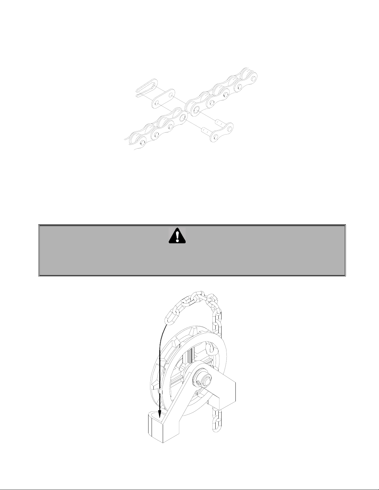
2. Connect the sprockets with the drive chain, shorten to a suitable length and join together with the chain link
provided in the hardware bag. To shorten the chain, punch out the pin that will leave an inside link nearest to
the desired length. Connect the chain around the sprockets using the chain link (Figure 9).
Figure 9 Chain link
3. Slide the operator or adjust position of angle hood mounted bracket to tighten the drive chain and then firmly
tighten the mounting bolts. Check the tension on the chain and the set screws on the sprockets (there should
be no more than 1/4" slack when chain is depressed between sprockets
4. Run hand chain through the pocket wheel and through the chain guide outside the frame (Figure 10), allow
both ends to hang down toward the ground and cut hand chain, if necessary, so that both ends are
approximately 2 feet (0.6 m) from floor. Connect both ends of hand chain.
CAUTION
BEFORE PULLING HAND CHAIN THROUGH POCKET WHEEL OR LIFTING THE DOOR DIRECTLY BY
HAND, PULL CAM PLATE AND SPIN CAM NUTS TO CENTER OF LIMIT SHAFT SO AS TO BE SURE
THE CAMS ARE NOT BEING MECHANICALLY DRIVEN THROUGH THEIR NORMAL LIMIT SWITCH
END POSITIONS.
Figure 10 Installing hand chain on Opera-GH
Page 10
10
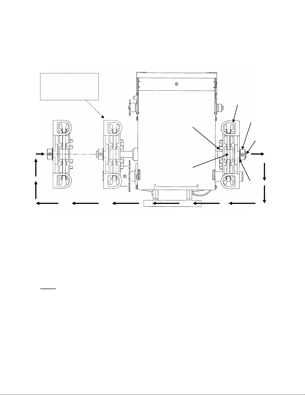
4.3 HOIST-A-MATIC
Opera-GH is designed with a self-engaging chain hoist with one step operation and automatic power cut-off.
No floor level disconnect is required which simplified operation and installation
The standard Opera-GH is provided with a chain hoist located on the right of the operator. If handing requires the
chain hoist to be on the left (rolling doors, left operator hood mounting for ex.), it could easily be transferred from
Right Hand side to Left Hand side in the field.
Figure 11 Changing the position of a manual Chain Hoist
Transferring the chain hoist from right to left or vice versa is done very easily in the field. No extra parts or any
kind of adjustment is required to change the location of the chain hoist. Refer to the above drawing (Figure 10)
STEP BY STEP INSTRUCTION OF TRANSFERRING THE CHAIN HOIST FROM RIGHT TO LEFT
Use an Allen Key to unscrew and remove the Collar 5/8’
Remove the Washer located in between the Collar and the Chain Guide.
Remove the Chain Guide
Remove the Pocket Wheel.
NOTE: Cutter pins are supplied on both sides of the hoist shaft.
Once these parts are removed from the right side of the hoist shaft, refer to the instructions below to mount
the chain hoist on the left side.
Place the Pocket Wheel against the Cutter Pin
Place the Chain Guide
Place the Washer against the Chain Guide
Put the Collar at the end and use an Allen Key to tighten the setscrew
Collar 5/8’
OGH hoist
shaft
Chain
guide
Cutter pin
Final position of the
chain hoist when it is
transferred from Right to
Left hand side
Pocket wheel
Washer
Page 11
11
3.4 ADJUSTMENT OF LIMIT SWITCHES
WARNING
NEVER PLACE HANDS OR TOOLS INSIDE OPERATOR OR NEAR DRIVE MECHANISM UNLESS POWER
IS OFF.
1. Open the cover of the electrical enclosure.
2. Manually raise the door to a nearly opened position.
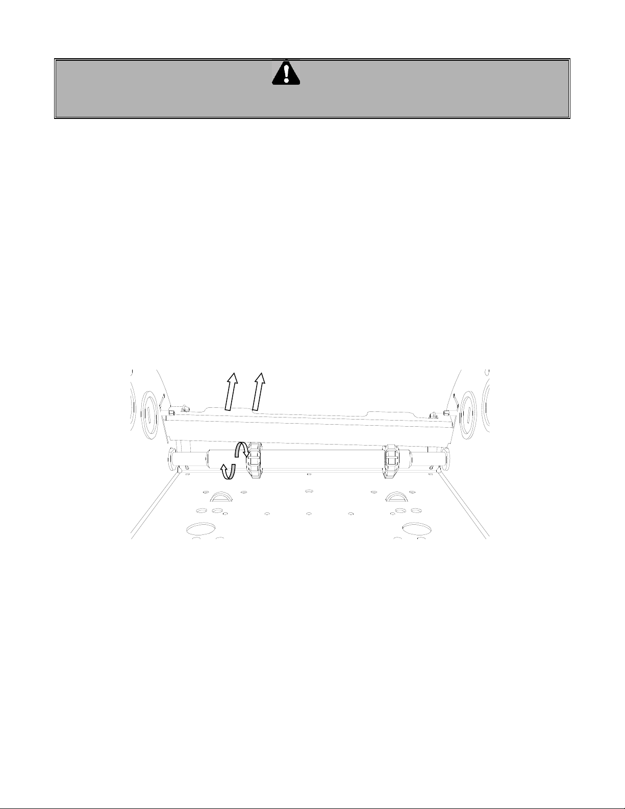
3. Pull the travelling cam retaining bracket on the Open Position cam side and rotate the Open Position cam
(Figure 12).
Note: Turning the cam towards the center of the shaft increases door travel.
Turning the cam towards the switch decreases door travel.
4. Manually rotate the Open Position cam until the lever activates the Open limit switch sufficiently so as to hear
the switch click.
5. Release and engage the retaining bracket. Make sure that the bracket engages in the slots of both limit
cams after each adjustment.
6. Manually lower the door to a nearly closed position and repeat steps 3 through 5 with the Close Position cam.
7. Upon completion of all wiring connections, repeat steps 2 through 6 using the "Stop" button for adjustments
of limit switches to their final, exact positions.
Figure 12 Adjusting the limit cams
3.5 MINIMUM SUGGESTED WIRE SIZE FOR CONTROL CIRCUIT
The control circuit operates at 24 VAC. Due to the resistance in the wire used to carry the control circuit voltage, it
is important to use the appropriate wire size with respect to the distance between the operator and the pushbutton station.
The chart (TABLE 2) indicating the minimum recommended wire size with respect to the total distance
between the operator and the push-button station. DO NOT exceed the maximum distance. If there are
several push-button stations in series you must ADD all these distances before selecting the appropriate wire
gauge for your operator.
If the wire gauge is not suitable for the distance, problems in operation will be encountered such as chattering
relays and contactor, premature wear of the contacts and possible tripping of the motor's thermal protection.
If a greater distance is required, a long distance interface module is suggested (consult factory).
When large gauge wire is used, a separate junction box will be needed for operator power connection (not
supplied).
Pull the traveling cam retaining bracket
on desired side to adjust cam position
Page 12
12
All power wiring to the operator should be installed by a qualified electrician and may vary with respect to conduit
size and type as specified in the National Electrical Code, Article 430, allowing 5% voltage drop. Power must also
be connected in accordance with local codes.
TABLE 2 WIRE SIZE vs. DISTANCE
24 VAC CONTROL WIRING
Minimum suggested
Wire gauge
(AWG)
Maximum distance between operator and all
Push-button stations
feet (meters)
22
50 (15)
20
100 (30)
18
150 (45)
16
250 (75)
14
350 (105)
12
450 (135)
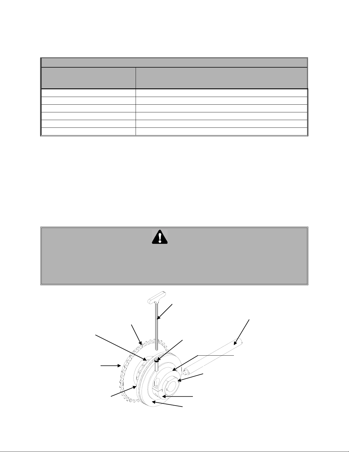
4.6 CLUTCH ADJUSTMENT (OPTIONAL)
1. Loosen clutch set screws (Figure 13)
2. Back off (rotate counter clockwise) clutch nut until there is insufficient tension to permit clutch to drive door
3. Tighten clutch nut gradually until there is just enough tension on spring to permit operator to move door
smoothly, but allow clutch to slip if door is obstructed.
4. When clutch is properly adjusted it should be possible to stop door by hand during travel.
5. Be sure to tighten clutch set screws each time operator is tested for clutch adjustment and that it is locked
in place on completion of adjustments.
WARNING
THE OPTIONAL FRICTION CLUTCH IS DESIGNED TO PROTECT VEHICLES AND DOOR
HARDWARE AGAINST DAMAGE. IT IS NOT INTENDED TO PROTECT PEOPLE. ALL DOORS
SERVING PERSONNEL ARE TO BE FITTED WITH AN APPROPRIATE REVERSING DEVICE OR
REVERSING EDGE TO PREVENT INJURY OR DEATH.
We strongly recommend the use of an automatic reversing device. Several types are available as
accessories. Consult your dealer for a recommendation.
Figure 13 Clutch adjustment
Socket Head
cap screw
Friction Disc
Pressure
plate
Slipping
Sprocket
Friction Disc
Pressure plate
Belleville washer
Hollow shaft
Clutch nut
Allen key
Clutch key
Page 13
13
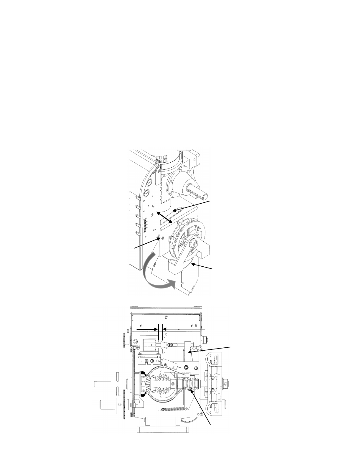
4.7 BRAKE ADJUSTMENT
1. The brake is factory set. However, after extensive use the brake may need to be adjusted.
2. In order to obtain best performance and maximum life, the brake must be adjusted for:
Proper clearance between the brake band and the brake drum when the solenoid is energized.
Correct brake tensioning when the solenoid is de-energized.
TO ADJUST THE BRAKE SYSTEM:
1. Remove the solenoid front cover by slightly unscrewing screws on each side of the frame. (Figure 14)
2. Slightly unscrew the pivot nut using the appropriate key (7/16”) or a nut driver (Figure 15).
3. Press the brake lever towards the solenoid (Figure 14) to adjust the gap between the plunger and the
solenoid body, meanwhile pull the brake adjustment lever away from the motor to put tension on the band
(Figure 14).
4. The gap between the plunger and the solenoid body should measure 1/4” to 3/8” wide (Figure 15).
5. Tighten the pivot nut, recheck the gap and also check the Brake adjustment:
Verify that the brake drum does not rotate by hand
Manually push the plunger onto the solenoid body and verify that the brake drum rotates easily by hands
6. Once the adjustment has been completed, reinstall the solenoid cover.
Figure 14 Brake system (right hand side view)
Figure 15 Brake system (front view)
Solenoid front cover
Adjustment lever
Solenoid
cover screw
7/16” as minimum gap
between the plunger
and the solenoid body
Pivot nut
Brake
lever
Page 14
14
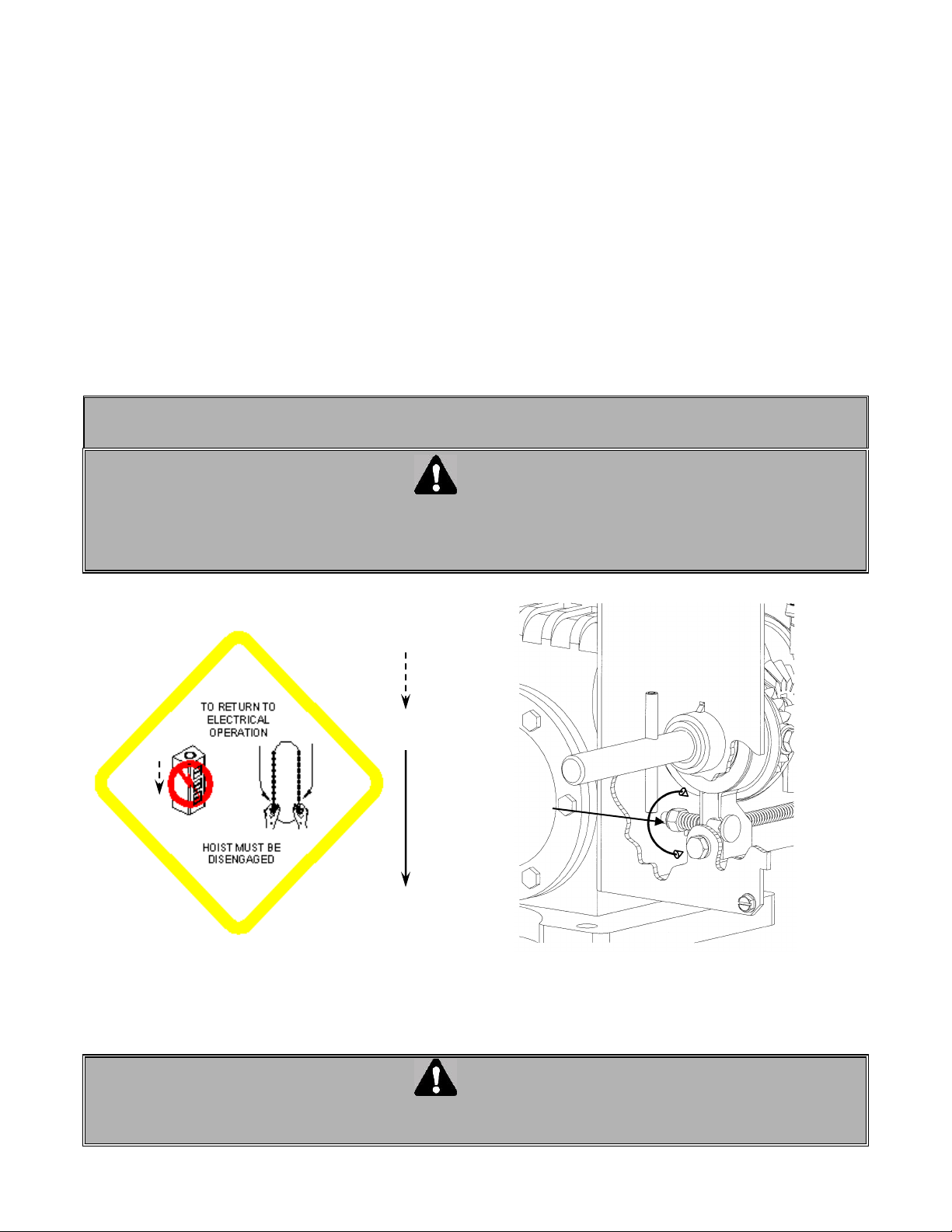
3.8 ADJUSTMENT AND MANUAL OPERATION OF OPERA-GH OPERATOR
The Opera-GH operator is equipped with an automatic emergency chain hoist disconnect mechanism to operate
the door manually, no floor disconnect is required.
In one simple step
Control circuit interrupted.
Hoist engaged.
Manual operations.
are successively completed by pulling the hand chain in the desired direction:
1. Firmly pull on the hand chain in the desired direction. The first foot pulled will engage the hoist
mechanism and open the electrical control circuit.
2. Continue the traction movement to move the door. If it doesn’t run in the desired direction, repeat actions 1
and 2 by pulling the chain in the other direction (See Figure 16).
3. The automatic hoist engagement system is adjusted in the factory. It may require adjustment in the field.
Adjustment is necessary if no door movement occurs after two feet of pulled hand chain. Turn the adjusting
nut clockwise (see figure 17) by ¼ turn until the hoist engages after pulling one foot of chain. If the nut is too
tight, the manual torque on the chain will be too heavy.
4. Return to the standard electrical operation.
IMPORTANT: To return to electrical operation, pull back 6 inches on the opposite direction of the chain.
WARNING
DO NOT ATTEMPT TO DISENGAGE THE OPERATOR WHILE OPERATOR IS RUNNING. DO NOT
ATTEMPT TO MANUALLY FORCE A MALFUNCTIONING DOOR TO OPEN OR CLOSE. THIS IS AN
EMERGENCY DEVICE AND IS NOT DESIGNED TO OPERATE A DOOR WITH SERIOUS MECHANICAL
PROBLEMS.
Figure 16 Operating chain to open and close door
Figure 17 Manual operation system adjustment
WARNING
ONCE ALL THE ADJUSTMEMTS ARE COMPLETED, THE SOLENOID FRONT SHOULD BE PLACED
BACK AND TIGHTEN THE SCREWS ON EACH SIDE OF THE FRAME
Engagement
Operation
Adjusting
nut
Page 15
15
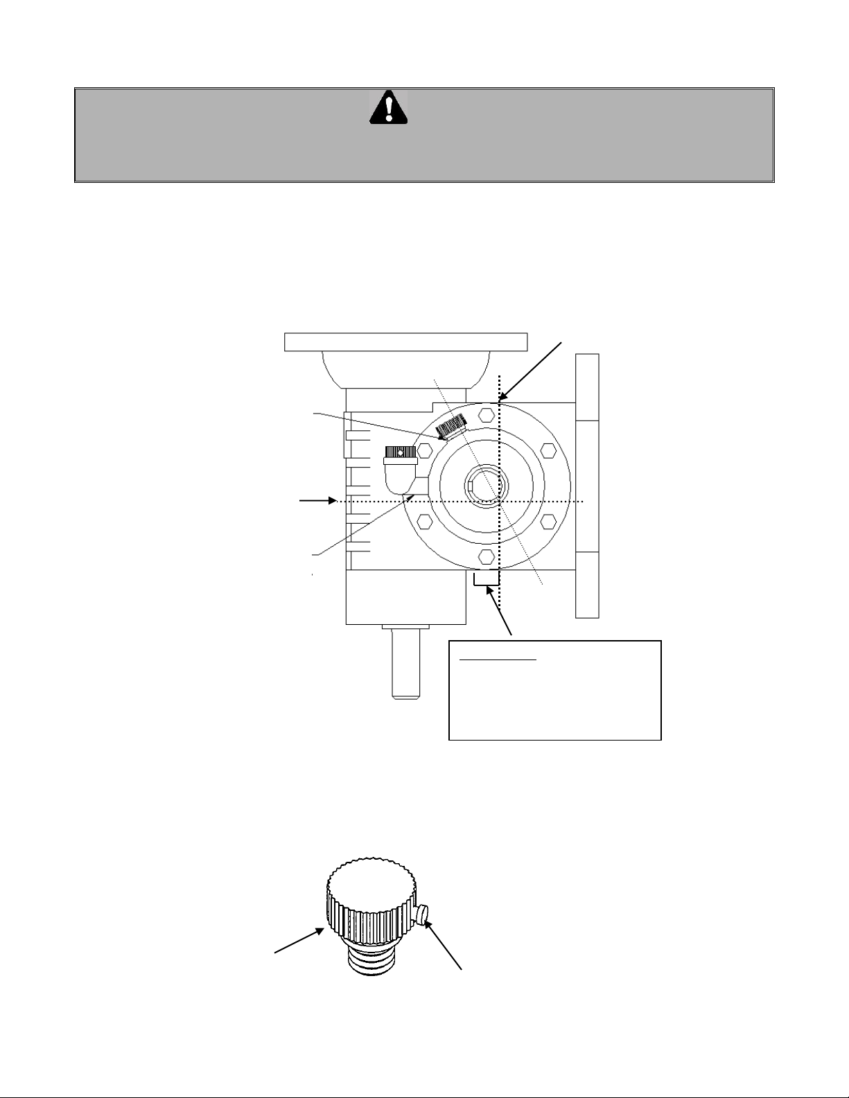
4.9 GEAR REDUCER BREATHER AND LUBRICANT
All Gear Head operators are supplied with a Reducer Breather. However, the breather is not mounted at the factory
to avoid leakage during handling of the reducer. All reducers are built with an air-vent hole to receive the Reducer
Breather. To prevent oil leakage during shipping and installation, a metal bolt is placed on the air-vent hole.
WARNING
TO AVOID THE RISK OF HAVING HIGH PRESURE IN THE REDUCER (GEAR BOX) AN OIL BREATHER
SHOULD BE INSTALLED ON THE GEAR REDUCER. FAILURE TO INSTALL THE BREATHER MAY LEAD
TO OIL LEAKAGE FROM THE SEAL AND DAMAGE THE REDUCER.
DRAIN BOLT: is located on the
bottom of the reducer to drain the
used oil. It is advised to bring the
operator down while changing oil.
Drain bolt must be properly
tightened to avoid oil leakage.
0°
Oil level when
operator is
installed
Oil level when
operator is on
horizontal position.
GEAR
MOTOR
REDUCER AIR BREATHER
Yellow Plug
(should be removed
after cap installation)
For reducer with vent
hole at 60° use cap
only as shown
For reducer with vent
hole at 90° use metal
elbow + cap as shown
Cap
60°
Page 16
16
HOW TO PLACE THE BREATHER IN THE AIR VENT HOLE:
The Breather consists of a Metal Elbow and a Screw-in Plastic Cap with a yellow plug.
The Breather on the reducer should be installed once the gear head operator is mounted. Install the breather
referring to the drawing shown (remove the metal bolt from the air vent hole):
If the air-vent hole is leaning at 60° or more, only the screw-in plastic cap must be used on the air-vent.
If the air-vent hole is leaning at less than 60°, the metal elbow and plastic cap must be used. Using only
the plastic cap will result in risk of oil leakage since the reducer is almost half full.
NOTE: Once the breather is installed, the yellow plug must be removed from the plastic cap to allow
free ventilation of the reducer.
MAINTENANCE:
The oil level in the reducer should be checked at least once a month. False readings can be avoided by
examining the oil on stationary reducer. Remove the breather and with the help of a long screwdriver or a
metal rod, check the oil level by inserting it inside the reducer. Under normal conditions, the oil level must be
near the middle of the drive shaft level. Never mix two different types of oil. If uncertain, change lubricant.
CHANGING LUBRICANT:
After 100 hours of running, a new reducer should be drained, flushed and refilled with proper oil. Thereafter,
oil should be changed at least every 2500 operating hours. Never mix two different types of oil. Be sure to
drain and wash before using another type of oil.
SELECTION OF LUBRICANT:
Lubricating oil must have a viscosity to reduce friction and allow the speed reducer to operate smoothly under
high load and impact. Consult the table below to select the proper lubricant (see table below).
Our gear reducers are normally filled up with oil of S.A.E. (Society of Automobile Engineers) grade 80W90,
where a wide temperature range is expected.
These kinds of lubricants permit extended life between drains. This is due to their increased resistance to
thermal degradation or oxidation.
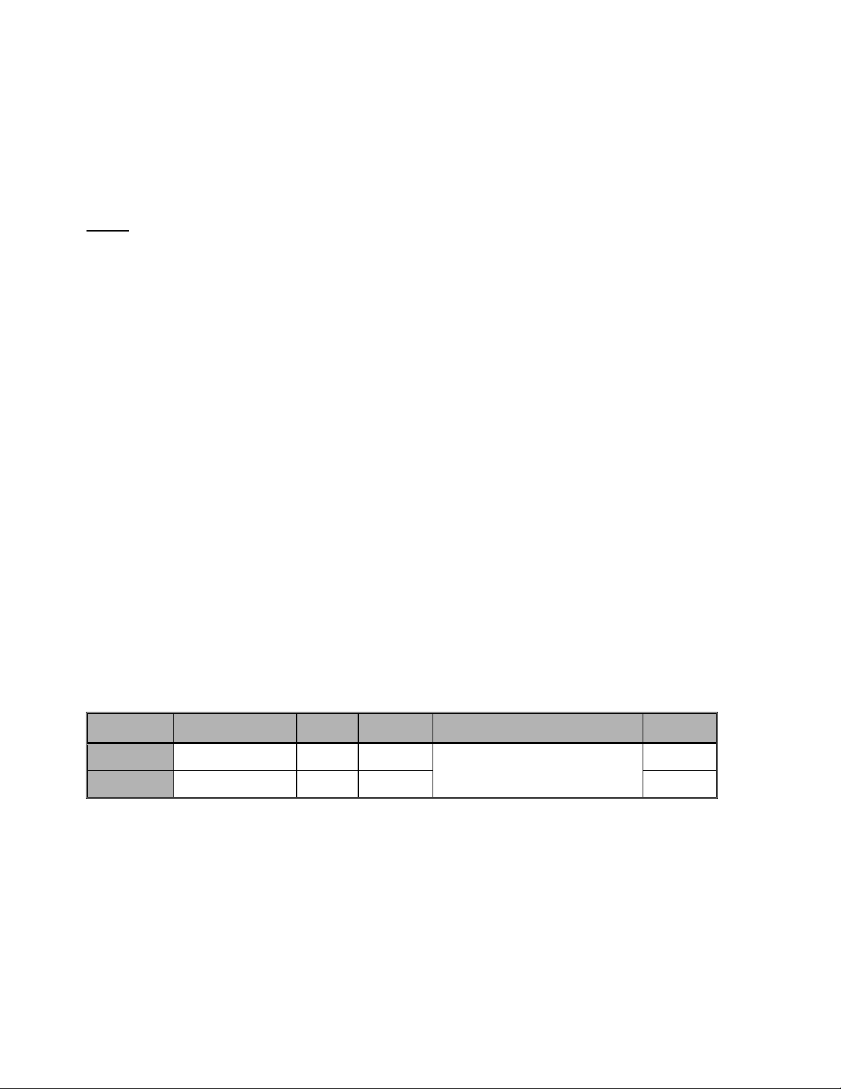
LUBRICANT TABLE
Operator
Model
HP
Ratio
Frame
Size
Oil to be used
Qty (ml)
OGH
1/2, 3/4, 1
45:1
56C
MINERAL ISO 150 or SAE
80W90
410
OGH
1 1/2, 2
44:1
56C
700
Page 17
17
5 SCHEDULED MAINTENANCE
Maintenance and supervision should be performed by qualified persons only.
Inspection and service should be performed anytime a malfunction is observed or suspected.
WARNING
WHEN SERVICING - ALWAYS DISCONNECT OPERATOR FROM POWER SUPPLY
5.1 MECHANICAL
The door area should always be kept clear of dirt, rocks or any other substance to insure proper operation.
EVERY 3 MONTHS
- Check and adjust the brake band and solenoid, if needed.
- Check and adjust the clutch, if necessary.
- Check all safety features if responding properly (photocells, pneumatic etc)
EVERY 6 MONTHS
- Check the oil level in the gearbox.
- Lubricate all moving parts, bushings are oil impregnated and are lubricated for life.
- Verify that all mechanical parts function properly.
- Inspect the V-belt and adjust or replace if necessary.
- Manually operate the door. If the door does not open or close freely, correct the
cause of the malfunction.
ONCE A YEAR
- Inspect all bolts and screws and tighten if necessary.
- Check for any excessive slack in chains and adjust or replace them if necessary.
The limit switches may have to be reset after a chain adjustment.
- Inspect the door for wear and damage.
- Run the operator a few cycles:
Make sure that the door rollers are rolling smoothly on the track.
Listen to the motor: The motor should hum quietly and smoothly.
Verify that the limit operates quietly and smoothly: investigate any unusual noise.
- Verify that the mooring bolts are holding the unit securely.
- Inspect the unit for evidence of corrosion.
5.2 ELECTRICAL
WARNING
BEFORE OPENING THE CONTROL BOX COVER, DISCONNECT OPERATOR FROM POWER SUPPLY
Inspect the unit for evidence of corrosion.
Inspect the wiring compartment and remove any dirt from the control units.
Check all the grounding wires and terminations for corrosion. Be particularly careful to check the ground wires.
Check the terminal strip to insure that all the screws are tight.
Verify that the safety edge or other safety devices installed on the operator are fully operational.
Check the voltage at the input terminals while the operator is running. The voltage must not drop more than 10%
momentarily. If the voltage drop is too deep when running, the relays may chatter, the contact points will wear
prematurely and may eventually weld. Check the power terminations for corrosion.
Check the current consumption of the unit with an amp-meter. The value of current should be consistent with the
nameplate specifications. Investigate any anomaly
Page 18
18
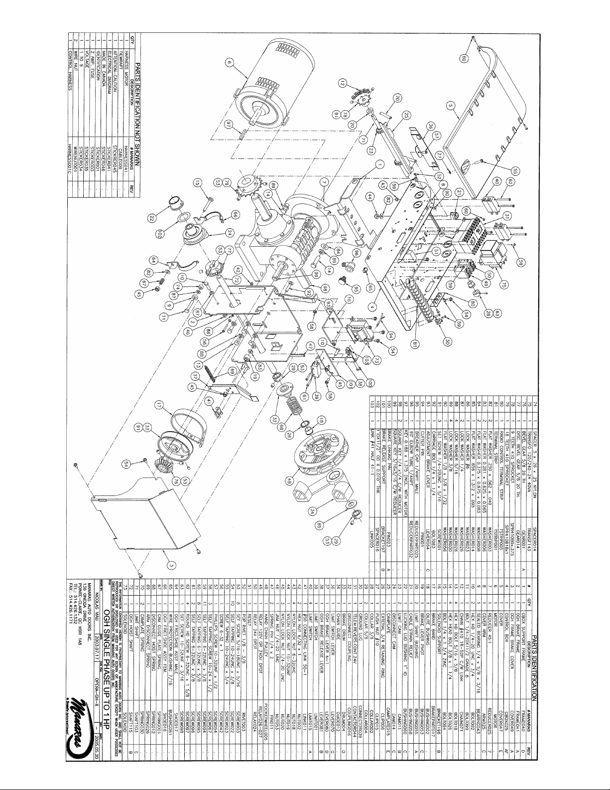
6 Opera-GH exploded view
Page 19

19
77..
SSppeecciiffiicc sseeccttiioonn ffoorr ooppeerraattoorrss ssuupppplliieedd wwiitthh
E
E
L
L
E
E
C
C
T
T
R
R
O
O
N
N
I
I
C
C
C
C
O
O
N
N
T
T
R
R
O
O
L
L
B
B
O
O
A
A
R
R
D
D
77..11 PPOOWWEERR AANNDD CCOONNTTRROOLL WWIIRRIINNGG DDIIAAGGRRAAMM
77..22 EELLEECCTTRROONNIICC CCIIRRCCUUIITT BBOOAARRDD
77..33 PPRROOGGRRAAMM SSEETTTTIINNGG
77..44 MMOODDEE SSEETTTTIINNGG
77..55 CCOONNNNEECCTTIIOONN OOFF RREEVVEERRSSIINNGG EEDDGGEE
77..66 DDOOOORR IINNTTEERRLLOOCCKK && FFRRIICCTTIIOONN CCLLUUTTCCHH
77..77 LLIIMMIITT SSWWIITTCCHHEESS
77..88 AADDJJUUSSTTMMEENNTT OOFF LLIIMMIITT SSWWIITTCCHHEESS
77..99 TTRROOUUBBLLEESSHHOOOOTTIINNGG GGUUIIDDEE
NNOOTTEE:: PPlleeaassee rreeffeerr ttoo ppaaggee 3311 ffoorr hhaarrddwwiirreedd ooppeerraattoorrss.
.
Page 20
20
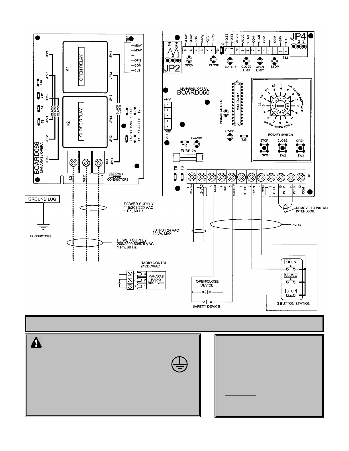
Before installing power and control wiring, be sure to follow
all specifications described below. Failure to do so may damage
the operator.
The operator must be properly grounded and connected in
accordance to local electrical codes.
Use different knockouts available on EACH side of the control box to
pass the power and control wiring through.
Ensure maximum separation between power wiring and low voltage
control wirings in the control box.
Please refer to next page for details.
If a push button is not used, a jumper
must be placed between #8 & #9
***Under this condition a stop command is
not available to stop the door during its
travel.
Please refer to Accessories Wiring
diagrams (TN005E) before connecting
any external accessories
2 Amp fuse is used to protect 24VDC
on electronic board and also the 24VAC
supply for auxiliary control devices
7.1 POWER AND CONTROL WIRING DIAGRAM
VERY IMPORTANT NOTES
Page 21
21
STATION031
AIRSWITCH007
Open
Close
Stop
Red
Yellow
8
7
NO
NC
NO
NC
NO
NC
9
Adjustment
3 5 6
KEYSWITCH019
6
7
8
9
KEYSWITCH015
Jumper must
be removed if
a station with
a stop button
is also
connected
6 7 8
9
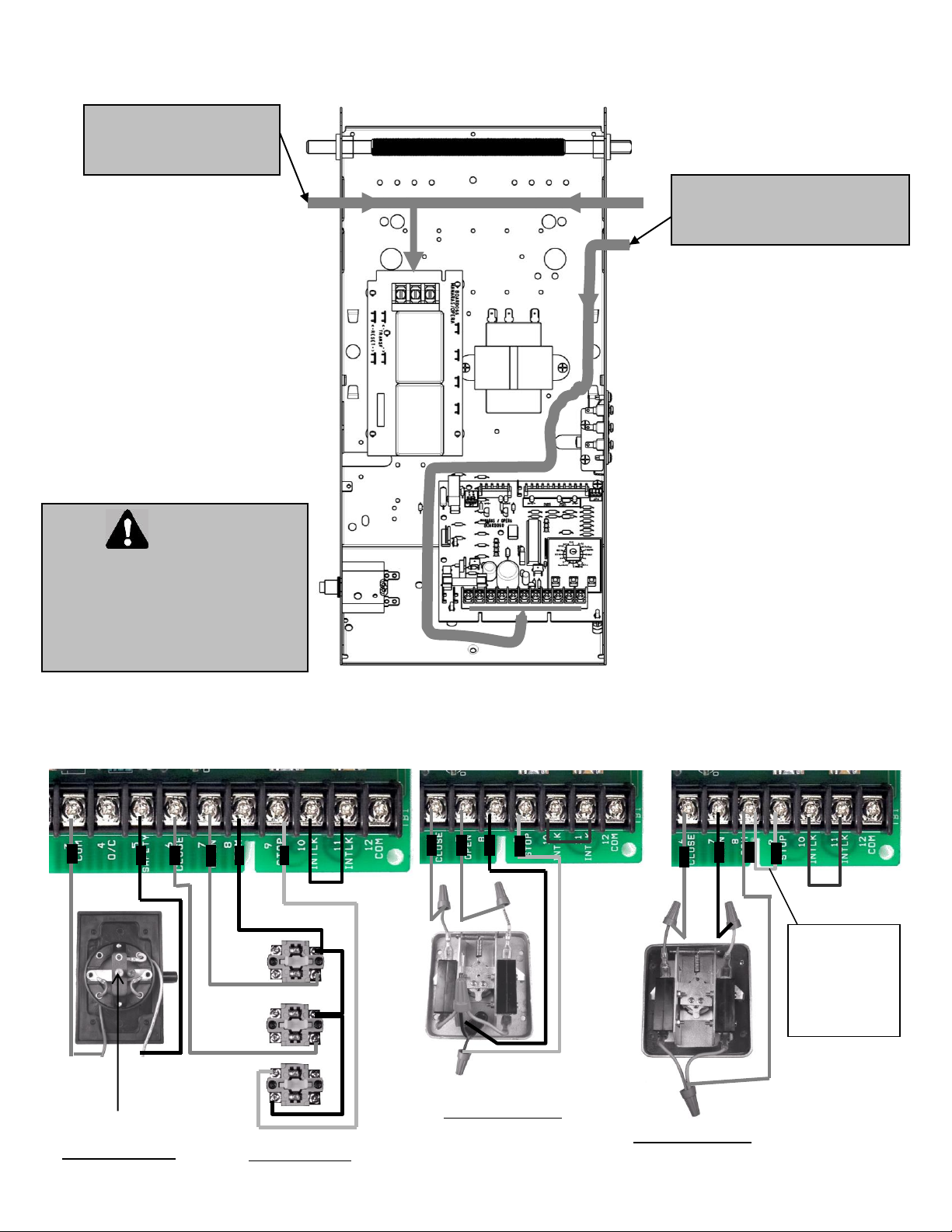
Route the power line wires
either from right or from left
of the control box.
Route all low voltage control wires
as shown. Keep low voltage wires
separate from line voltage wires.
LOW VOLTAGE (controls) AND HIGH VOLTAGE (power) WIRINGS.
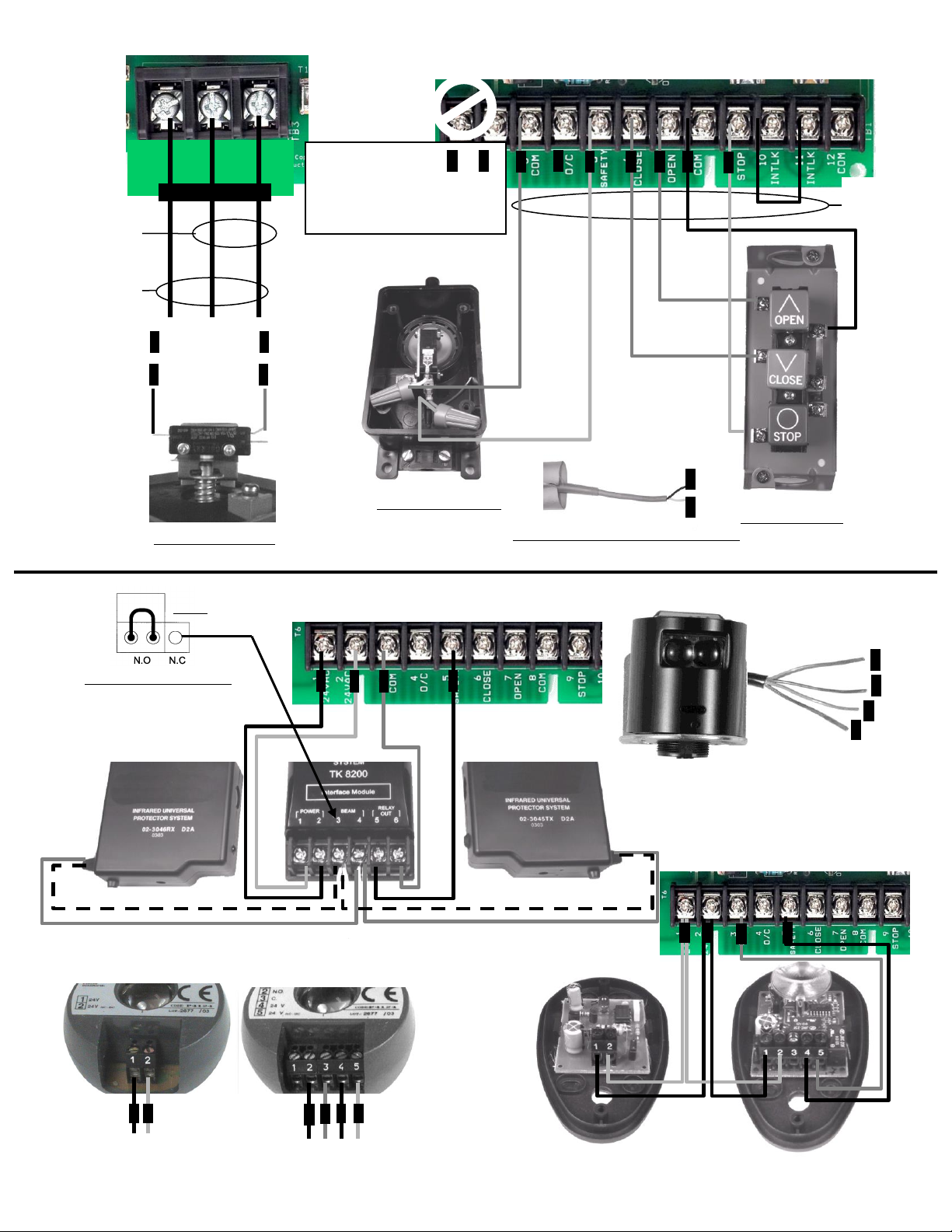
Accessory Wiring
WARNING
Wall control(s) must be located so
that the door is within sight of the
user.
If momentary contact (B2 mode) is
used, an external reversing device
must be install.
Page 22
22
L3
N/L2
L/L1
AIRSWITCH009
STATION020
PULLCORD003
Open/Close
Open Only
7 3 4
3
115/208/230 VAC
1 Ph. 60 Hz
208/230/
460/575 VAC
3 Ph. 60 Hz
24VAC (10VA MAX.) ONLY FOR THE
SUPPLY OF PHOTOCELLS, LOOP
DETECTORS, KEYPADS…
2 1 4
Power Supply
White
Green
3 5 6 7 8
9
Circuit
5V DC
3
5
2-wire Electric Sensing Edges
White
Brown
Blue
Orange
5
2
1
3
PHOTO038
PHOTO051
1
2
5
3
1 3 2
2
1
5
PHOTO044
PHOTO008
3
5
2
Black & white
White
Black & white
White
1
Interface Module Jumper
(TK8200)
Always set the jumper
located inside the
Interface Module on
N.O (Normally Open)
NOTE
Page 23
23
7.2 ELECTRONIC CONTROL BOARD
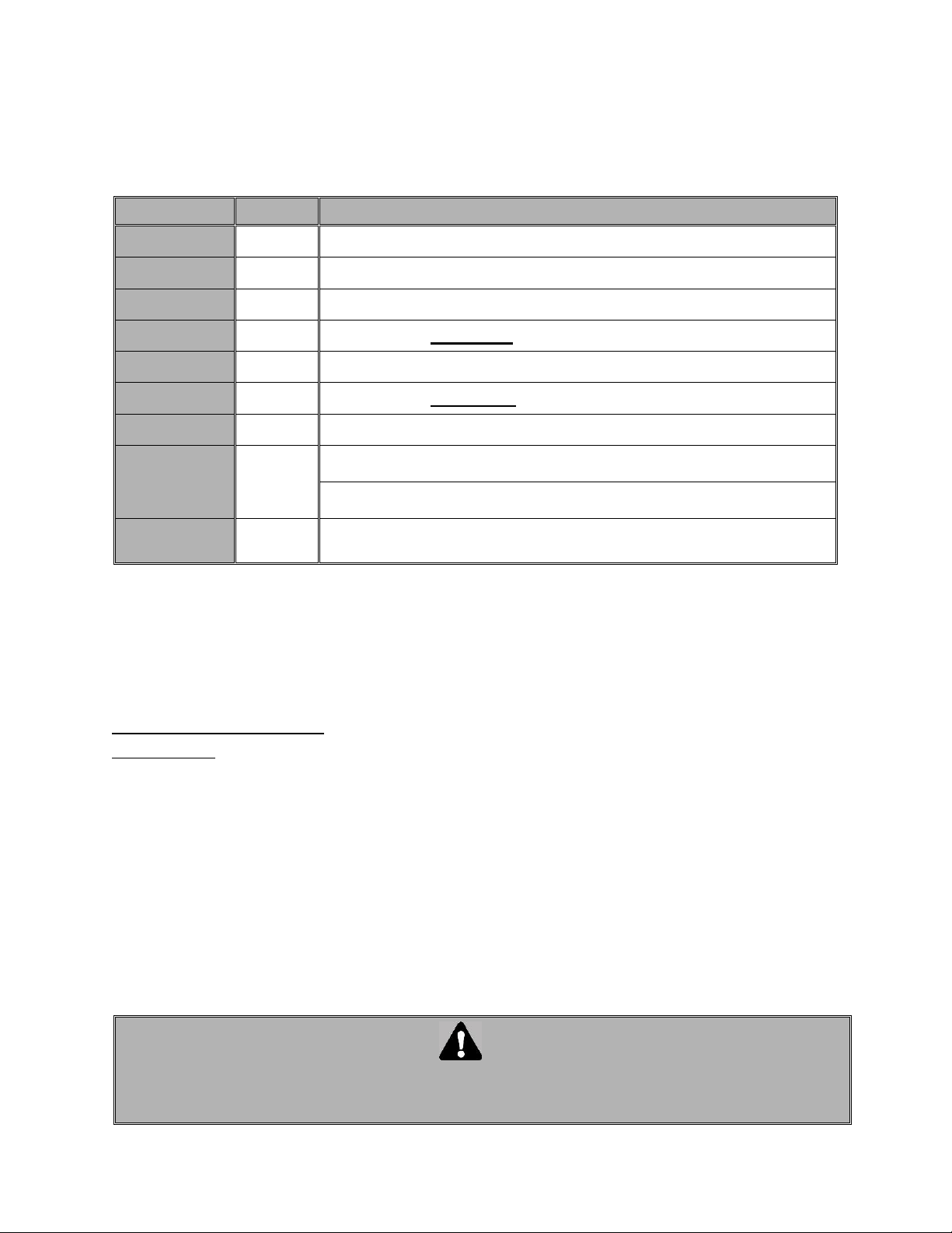
LED MONITORING STATUS
LED’s on the ECB help will wiring and making troubleshooting diagnoses. Every LED states the actual position
of the door. The board has a non-volatile memory and all the LED return to their initial state after a power
interruption.
WRONG HANDLING
Wrong handling protection prevents the operator from over passing the limits when incoming 3-phase power or
a single-phase motor are incorrectly connected.
When the operator turns in the opposite direction and reaches the wrong limit switch, the LED indicator
flashes-on and all the external commands are ignored by the electronic board.
To correct the problem when:
Stop LED OFF:
Check if the Stop button is properly connected on #8 and #9 or if a Normally Closed contact is used.
Verify if the Hoist is properly engaged and if the Hoist switch is closed (or if any external interlock device is
remained open)
EXTERNAL CONTROLS
Refer to the wiring diagram on page 20 before connecting power or any external device to the ECB. Neglecting
to use the proper terminals will result in complete damage to the ECB. If you are not certain about procedures,
please consult Manaras for assistance.
NOTE: Do not attempt correction by reversing wires on control station.
L.E.D
Color
STATUS
+24 V
Green
When ON indicates the presence of 24VDC on the Logic Board
+5 V
Green
When ON indicates the presence of 5VDC power in the Control Circuit
Open Limit
Red
When ON indicates door position, completely open.
Open
Red
Only when the open relay is activated (open relay is energized)
Close Limit
Red
When ON indicates door position, completely close.
Close
Red
Only when the close relay is activated (close relay is energized)
Safe
Red
Light ON only when safety devices are activated.
INDICAT
(Wrong
Handling)**
Red
Flashes only when motor runs in opposite direction and activates the
wrong limit switch.
Stay ON only when the “centrifugal switch” is opened (please contact
technical support)
STOP
Yellow
In normal conditions light; stay ON, goes OFF every time when press
STOP button or hoist is engaged
WARNING
WHEN REPLACING AN ELECTRONIC CONTROL BOARD DO CHECK THAT ALL JUMPERS ARE
POSITIONED AS INDICATED IN THE WIRING DIAGRAMS ON PAGE 27 FOR SINGLE PHASE AND
ON PAGE 28 FOR 3-PHASE.
Page 24
24
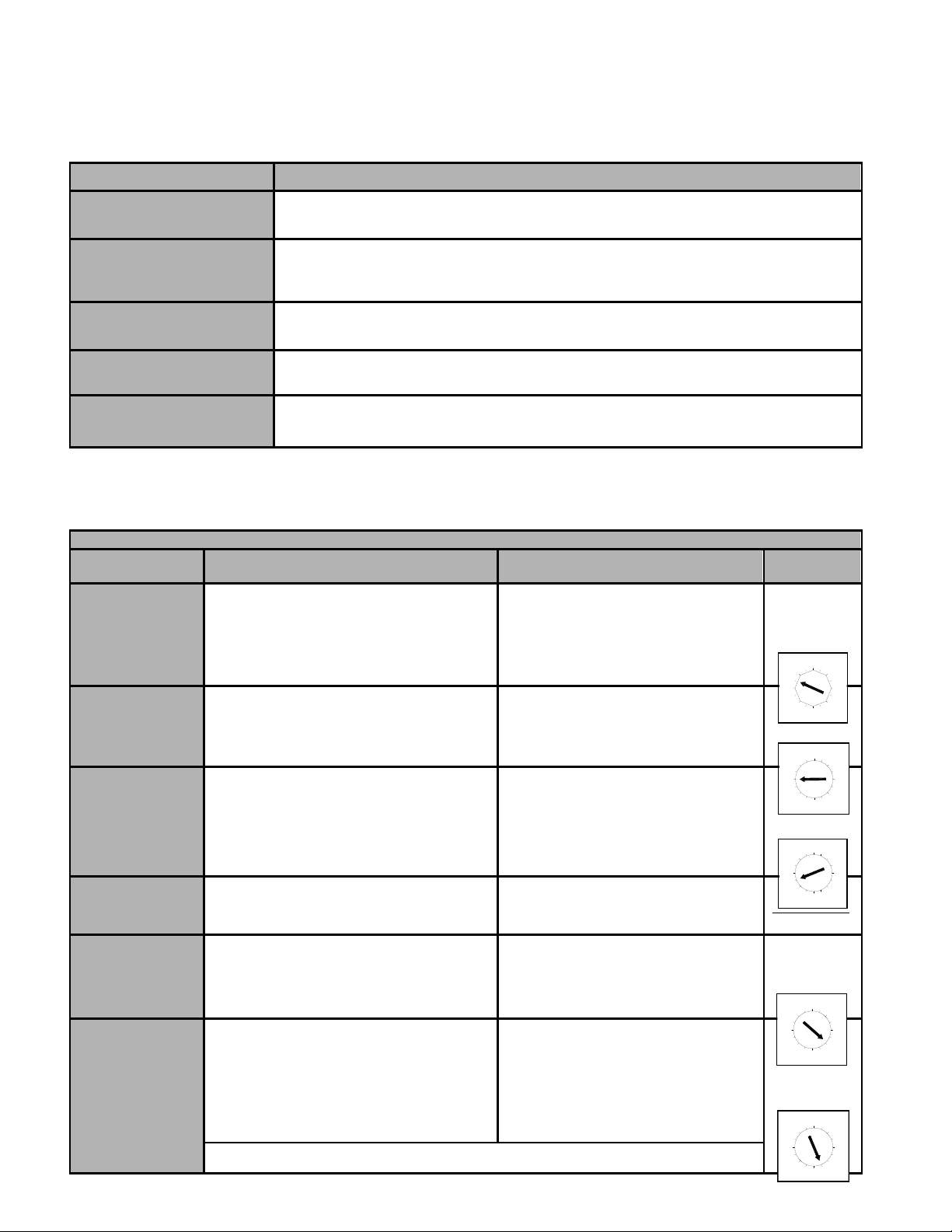
PROGRAM AND PROGRAM SETTINGS
Programming ability and door control at electrical box are provided by Open/Close/Stop buttons and Select Switch
located on the ECB.
Programs
7.3 PROGRAM SETTING
Door should be in fully closed position while setting one of these following programs.
PROGRAMS
FUNCTIONS AND DESCRIPTIONS
RUN TIMER
The Run Timer stops automatically the operator after an adjustable time delay either travelling
upwards or downwards. The Run Timer is designed to protect the door and the operator by
preventing the motor over running much longer than the normal time.
MID-STOP
Mid-Stop function will, when active, move the door from the down position to a predetermined
Mid-stop position when the open button or Open/Close device is activated. Once at Mid-Stop,
subsequent Open/close commands will close the door. To move the door to full open position, the
open button must be pressed again.
TIMER TO CLOSE
Timer to Close is a function that, when active, will close the door after an adjustable time delay
once the door has reached its fully open and mid-stop position. The timer to close function works
only in T and TS modes.
TIMER TO CLOSE (from
fully open position only)
Option used in conjunction with MID STOP function. When activated, Timer to Close is active
from the fully open position only and not from the mid-stop position.
ADVANCE CLOSED TIME
This feature, when programmed, allows adjustment of the safety device disabling point and to
determine the final stop point of the door once the “close limit switch” is activated. No “advance
close limit switch” is needed with this feature.
PROGRAM SETTING
PROGRAMS
ACTIVATE
DEACTIVATE
SELECT
SWITCH
RUN TIMER
Check if close limit switch is activated.
Set select switch on D.
Press “Open” button to add 10 sec to the
total time needed to open the door.
Set the select switch on (0,1 or 2)
Set select switch on D.
Press “Stop” button.
MID-STOP
Check the close limit is activated.
Set select switch on “C”
Press “Open” button then press “Stop”
button on desired Mid-Stop position.
Set select switch on “C”
Press “Close” button.
TIMER TO CLOSE
Set select switch on “B”
Press “Open” button to add 15 sec or “Close”
button to add 1 sec each time (max. 4
minutes & 30 seconds)
Set the select switch on T or TS mode
Set select switch on “B”
Press “Stop” button the timer to close is
reset to 0 sec but still activated.
To defeat the timer to close completely
set the switch on desired position (0, 1,
2 or 3)
DEFEATE TIMER
TO CLOSE
(from floor level)
Press the “Stop” four times continuously on
the push button station.
(operator will operate as B2 mode)
Press the “Close” button four times
continuously on the push button station.
(operator return to T or TS mode)
Not required
TIMER TO CLOSE
(from fully open
position only)
Set select switch on ”6”
First press the “Close” button and then the
“Stop”
Set select switch on “6”
Press “Close” button.
*Now the Timer to Close works from fully
open and Mid-Stop position.
ADVANCE CLOSED
TIME
Set the select switch on “7”
Press “Open” to add 50 milliseconds up to
500 milliseconds max.
Press “Close” to deduct 50 milliseconds each
time till it reaches 0/sec.
By pressing “Stop” the default time will
be set to 100 milliseconds.
* LED “INDICAT” comes ON only when time
is increased or reduced. LED OFF when
open or close button is pressed indicates
“Advance Close Time” is reached Maxi or
Mini. (pressing “Stop” LED ON = 100
milliseconds)
The ‘’close limit switch’’ should be readjusted when the ‘’advance closed time’’ is
programmed or deactivated
8
9
D
B
A
C
E
F
0
7
2
6
5
3
4
1
D
C
B
A
9
8
F
E
0
3
6
5
7
4
2
1
D
A
B
C
9
8
F
E
0
4
6
5
7
2
1
3
0
F
D
B
C
A
9
8
E
1
6
7
5
2
4
3
0
D
B
C
A
9
8
F
E
5
6
7
2
1
3
4
Page 25
25
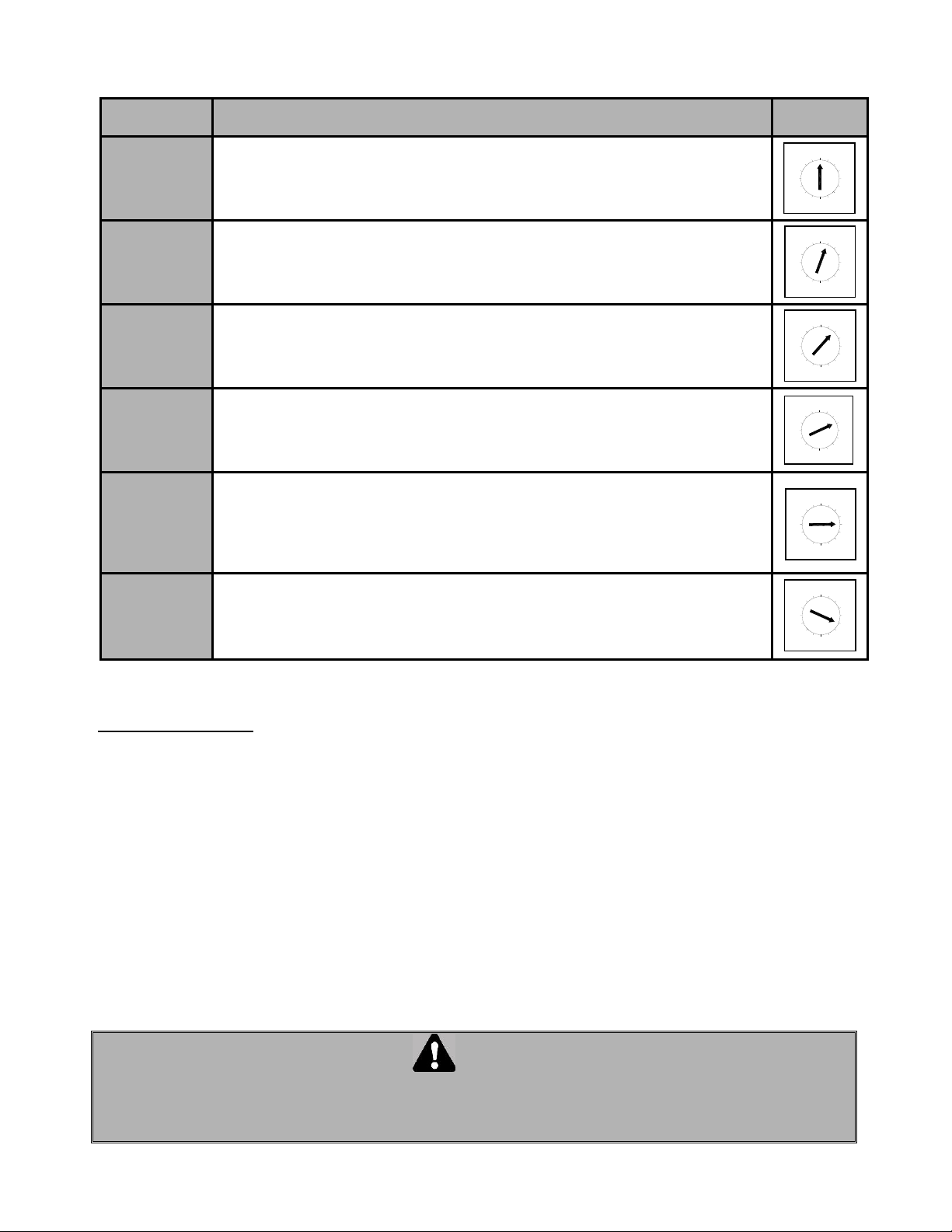
7.4 MODE SETTING
Wiring Type
Wiring Type & Functions
Select
Switch
C2
(factory
preset)
SET SELECT SWITCH ON 0
Momentary contact to open and stop, constant pressure to close with 3 buttons station.
Activation of safety devices will reverse the door during closing. Auxiliary devices
function as an Open control and to reverse door during closing.
B2
Set the select switch on 1.
Momentary contact to Open/Close and Stop with 3 buttons station. Activation of safety
devices will reverse the door during closing. Auxiliary devices function as Open/Close
control and reverse the door during closing.
D1
Set the select switch on 2.
Constant pressure to Open and constant pressure to Close. Activation of safety
devices will stop the door during closing.
E2
Set the select switch on 3
Momentary contact to open and constant pressure to Close. Release of Close button
activates the door upwards. Activation of safety devices will reverse door motion to fully
open position.
T
Set the select switch on 4.
Momentary contact to Open / Close and Stop. Timer to Close if programmed, safety
devices reverse upon but will disable Timer to Close. Timer to close will also be
disabled if there is a power outage, a chain hoist is engaged or the stop is pressed
before elapsed time. The timer resumes its normal operation, once the close cycle is
completed.
TS
Set the select switch on 5.
Momentary contact to Open / Close and Stop. Timer to Close if programmed,
safety devices reverse upon activation and will refresh Timer to Close. Timer to
close also gets refreshed, if there is a power outage, a chain hoist is engaged or a
stop button is pressed before elapsed time.
IMPORTANT NOTES:
STOP JUMPER
While testing the operator or adjusting the cams using the O/C/S buttons available on the Electronic
Control Board, a jumper should be placed between the #8 & #9. Once the tests or adjustments completed
the jumper should removed before connecting the wall 3-push buttons station. Failure to remove the stop
jumper, the STOP BUTTON WILL NOT RESPOND.
A stop jumper should be installed between #8 & #9 when using a Key switch, a single button Radio
control or a 2-buttons station (Open/Close). IN THESE CONDITIONS NO STOP COMMAND IS
AVAILABLE TO STOP THE DOOR DURING THE TRAVELLING.
WARNING
MOTORIZED DOORS CAN CAUSE SEVERE INJURY OR DEATH. MANARAS STRONGLY
RECOMMENDS THE USE OF ENTRAPMENT PROTECTION SYSTEMS, ESPECIALLY IN THE CASES
OF MOMENTARY CONTACT TO CLOSE (B2 WIRING) AND TIMER TO CLOSE (T & TS).
7
1
0
F
D
B
C
A
E
9
8
6
5
4
3
2
1
F
0
9
A
B
C
D
E
6
7
8
2
3
4
5
7
1
E
C
B
D
A
9
8
F
0
5
6
4
3
2
1
7
C
D
E
B
A
9
8
F
0
6
5
2
4
3
7
1
C
D
B
A
E
9
8
F
0
6
4
5
2
3
1
7
D
E
B
A
C
9
8
F
0
3
6
5
4
2
Page 26
26
7.5 CONNECTION OF A REVERSING EDGE DEVICE
IMPORTANT NOTE
IF THE DOOR IS CONTROLLED BY ANY DEVICE OTHER THAN A CONSTANT PRESSURE PUSH-BUTTON
STATION, A REVERSING EDGE MUST BE CONNECTED.
CAUTION: CONNECT REVERSING DEVICE APPROPRIATE TO INSTALLATION.
Connection and installation of a reversing edge device is provided with the edge (Figure 18 and Figure 19). Any such
device that uses a normally open contact may be connected to terminals #3 and #5 on the low voltage terminal block.
When the door comes in contact with an object during downward travel, the circuit will cause the motor to reverse the
door to the fully open position. In addition, there is a cut-off limit switch (advance close limit switch) that will de-activate
the reversing edge during the last few inches of the door's downward travel.
Figure 18 Reversing Edge
Figure 19 Reversing Edge
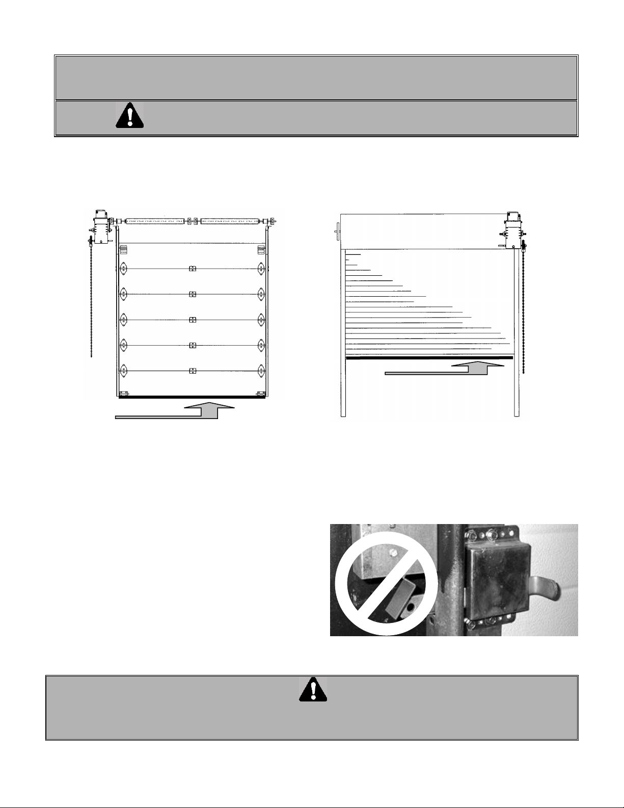
7.6 DOOR LOCK SENSOR & FRICTION CLUTCH
Please read carefully prior to installing this operator
Operators supplied with an electronic control board are equipped with the “DOOR LOCK SENSOR” feature.
The DOOR LOCK SENSOR prevents any damage to the
door when the door lock hasn’t been removed prior to
electronic operation. It eliminates the need of expensive
external interlock wiring.
This feature can only be used on operators equipped
with a FRICTION CLUTCH.
When the lock stops the door, the clutch slips and in less than
1 second, the door will reverse a fraction of a second to
release the lock.
WARNING
IF A CLUTCH IS USED IT SHOULD BE ADJUSTED ON SITE ONCE THE OPERATOR IS MOUNTED.
IN ORDER NOT TO DAMAGE THE DOOR WHEN THE LOCK IS ON, THE FRICTION CLUTCH HAS TO BE
ADJUSTED PROPERLY ACCORDING TO THE INSTRUCTIONS ON PAGE 12
Reversing edge location
Reversing edge location
Page 27
27
7.7 LIMIT SWITCHES
WARNING
TO AVOID THE DANGER OF POSSIBLE DAMAGE TO THE DOOR AND OPERATOR, TRAVELLING CAMS
MUST BE ADJUSTED TO THEIR APPROXIMATE POSITIONS BEFORE MANUALLY OPERATING THE
DOOR OR BEFORE APPLYING POWER TO THE OPERATOR.
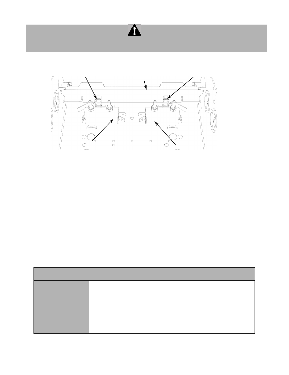
Only 2 limit switches are used in operators built with an Electronic Control Board. One for the “Open” side and
one for the “Close” side. No advanced Open or Closed limit switches is used. The microprocessor with the
built-in logic replaces the advanced Open and Closed limit switches (Figure 20)
7.8 DESCRIPTION LIMIT SWITCHES
The “Open” limit switch is the end of travel in the open position. Adjust the cam so that the door stops in
the open position at the desired location.
The “Close” limit switch is the end in the close position. Adjust the cam so that the door stops in the
closed position at the desired position.
7.9 TROUBLE SHOOTING AN OPERATOR WITH ECB
Troubleshooting an operator with an ECB is easier since the LEDs provided on the circuit board help to bring
a better diagnostic while finding faults.
Figure 20 Limit switches
Easy fix
Check the followings that may prevent the operator from starting
before coming to any conclusion
Check light status on
the ECB
Before starting any intervention, check the LEDs status and refer to the page
21 for a proper diagnostic.
Check the operating
modes
Review the operating modes: B2, C2, D1, T or TS
Check the
programming
A wrong programming on Timer to Close or Mid Stop will stop the door to an
improper position.
Check the presence
of stop jumper
If the 3 test buttons are being used without the stop jumper between #8 &
#9, the operator will not respond to the on board 3 buttons command
"Open" limit switch
"Close" limit switch
‘’Open Position’’ cam
Cam retaining plate
"Close Position" cam
Page 28
28
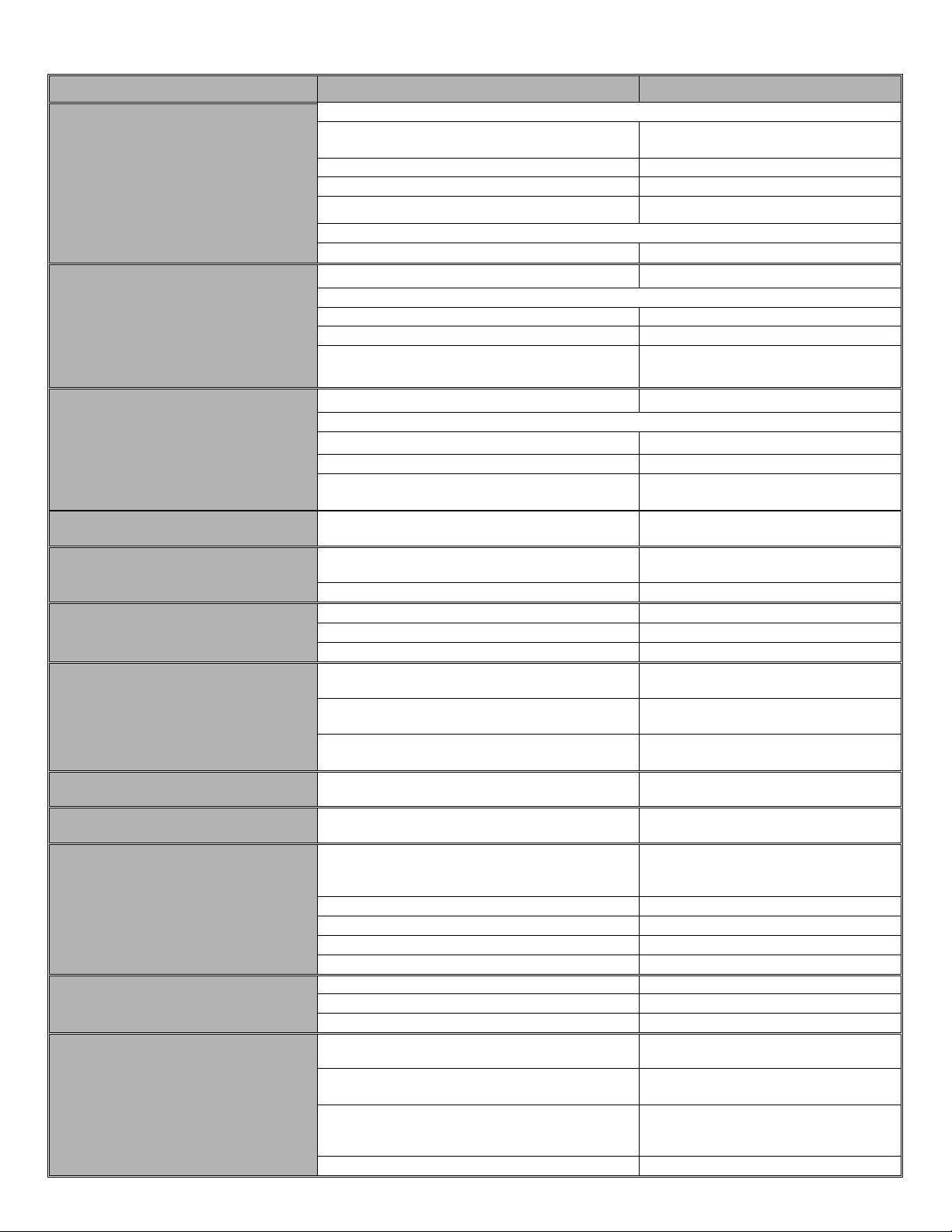
TROUBLE SHOOTING GUIDE
SYMPTOM
PROBABLE CAUSE
SUGGESTED ACTION
Door will not respond to « open »
or « close » push buttons
Check if STOP Led: if OFF.
Check if hoist is not engaged.
Disengage the hoist. (JP4 on 2-3 for
trolley & sliding operators)
Defective “stop” push button.
Replace.
Check wiring from push button to operator
Replace if needed.
Loose connection in one of the push buttons.
Verify, tighten or replace
If STOP Led is ON.
Defective “open” or “close” push button.
Replace.
Door will not respond to “open”
command, but will respond to
“close” command
Check the “open” Led: if OFF
Replace the board
If “open” Led is ON
Defective “open” push button
Replace.
Defective “open” limit switch.
Replace.
Loose wire on “open” push button, “open” limit
switch.
Verify, tighten or replace.
Door won’t respond to “close”
command, but will respond to
“open” command
Check the “close” Led: if OFF
Replace the board
If “close” Led is ON
Defective “close” push button.
Replace.
Defective “close” limit switch.
Replace.
Loose wire on close push-button, close limit
switch.
Verify, tighten or replace.
Door move in wrong direction
single or 3-phase operator
Motor rotation is reversed on board motor
terminals.
Interchange #T13 and #T14 on the
power board.
Stop button doesn’t stop the door
Two 3-push button stations connected in
parallel.
Correct wiring (only stop buttons in
series)
Bad stop button.
Check and replace.
Sensing edge does not reverse
door
Pneumatic hose broken.
Check and adjust.
Bad air switch.
Check and adjust.
Bad wiring.
Check and correct wiring.
When door closes it reverses to
fully open after it hits the floor
The advanced close time is not proper
adjusted.
Check and adjust.
The close limit switch is not being engaged by
traveling cam.
The close limit switch needs to be
adjusted properly at the end of travel.
An “open” command is given.
Check “open” push button or any
opening device for short-circuit.
Motor hums, starts when spun
(1 ph)
Capacitor defective.
Replace.
Motor relais buzz for a few seconds
when door is stopped (1 ph)
Bleeder resistor faulty on capacitor.
Replace.
Motor fails to shut off at fully
closed or opened position
Defective limit switch.
Operate limit switch manually while
door is moving. If door does not stop,
replace the switch.
Limit cams are not adjusted.
Verify and adjust.
Limit drive chain broken.
Replace.
Loose sprocket on limit shaft.
Tighten setscrew.
Limit shaft does not rotate.
Verify and replace accordingly.
Motor turns but door does not
move
Sprocket key is missing.
Replace.
Drive chain broken.
Replace.
Limit shaft does not rotate.
Adjust clutch tension.
Limit switches do not hold their
setting
Loose drive or limit chain allows chain to jump
sprocket teeth.
Adjust chain to proper tension.
Limit cam retainer not engaging slots in limit
cams.
Be sure retainer is in slots of both
cams.
Limit cams are binding on shaft threads, which
allow them to jump position on retainer.
Lubricate shaft threads. Limit cams
should turn freely.
Limit shaft have a light.
Verify and adjust.
Page 29
29
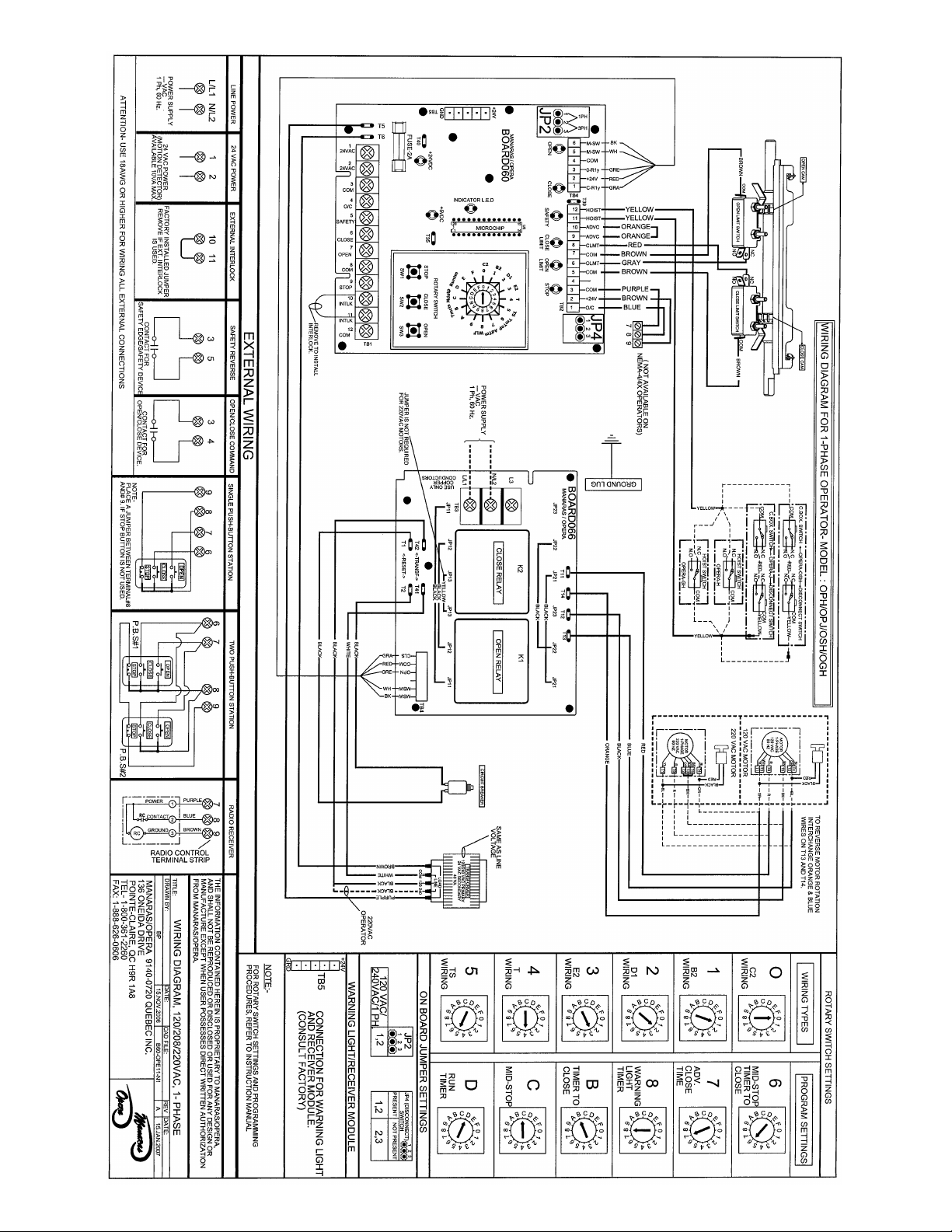
7.10 Single phase ECB wiring diagram
Page 30
30
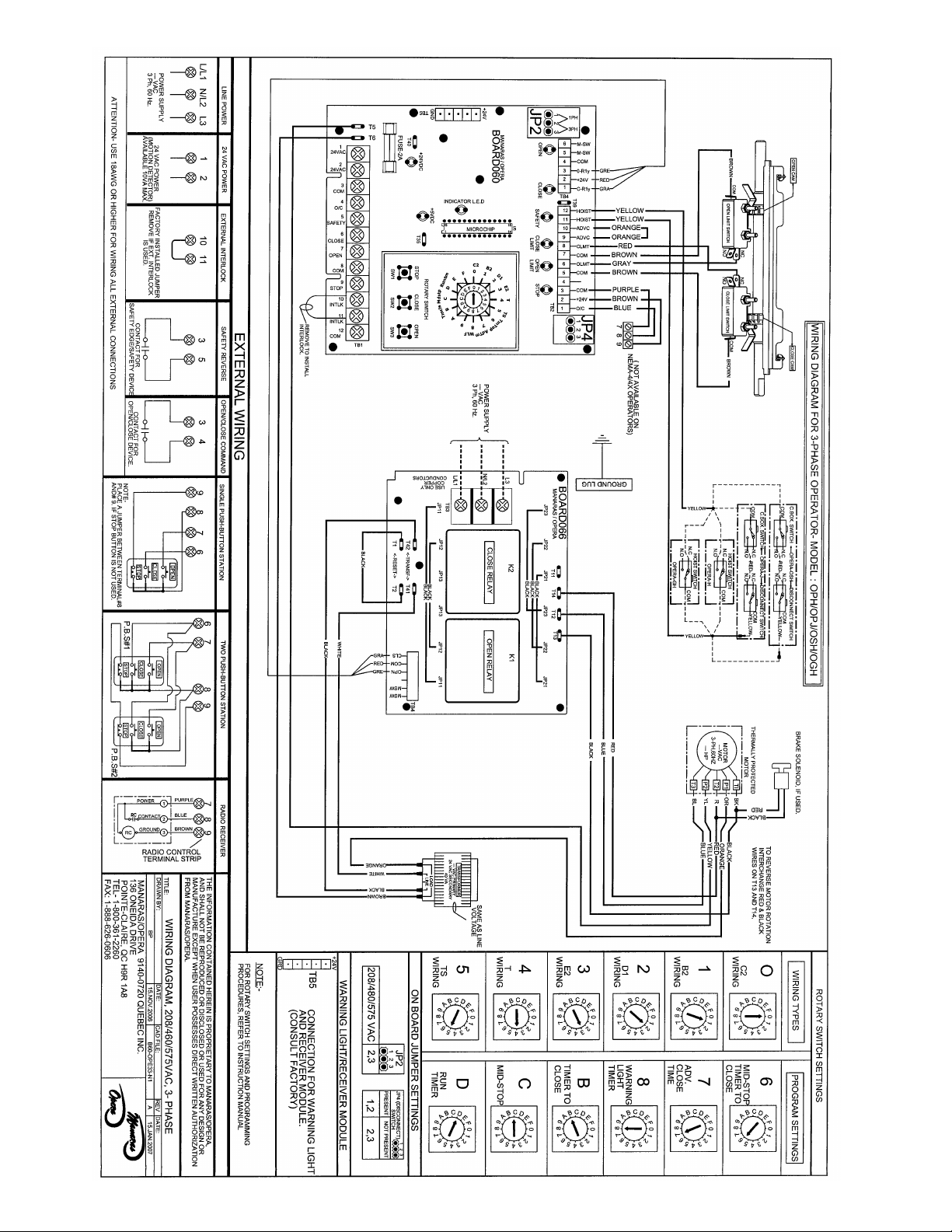
7.11 3-Phase ECB wiring diagram
Page 31

31
88.
.
SSppeecciiffiicc sseeccttiioonn ffoorr ooppeerraattoorrss ssuupppplliieedd wwiitthh
E
E
C
C
B
B
&
&
W
W
A
A
R
R
N
NII
N
N
G
G
L
LII
G
G
H
H
T
T
S
S
((RREEDD && GGRREEEENN)
)
Page 32
32
L
N
Green
Red
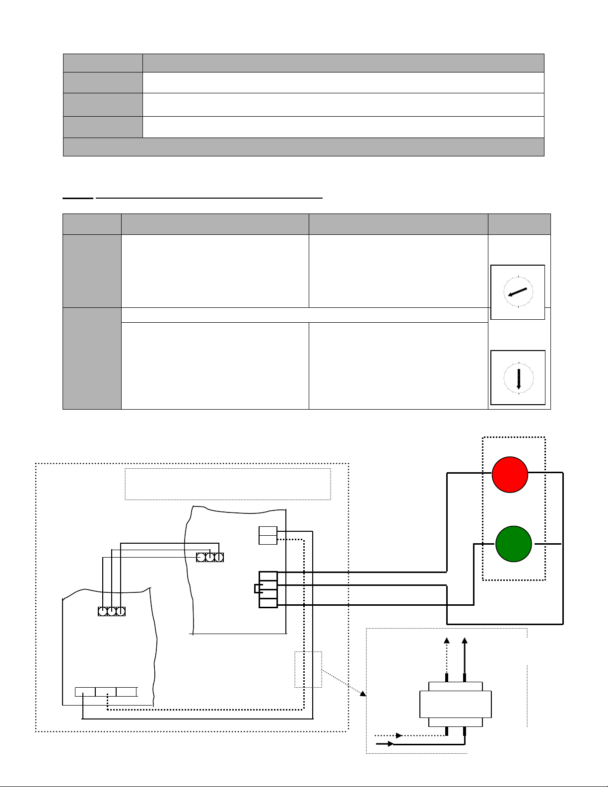
8.1 Warning Light Sequence
8.2 Programming warning lights sequence (door should be in the closed position)
NOTE: Warning lights is functional only with Timer to Close
8.3 Connection of Red and Green warning lights
(If Warning Lights Module is sold separately)
Lights
Operating sequence
Red
The light is solid red when the door is closing and opening. Light turns OFF once the door
reaches the fully open or fully closed position
Green
The green light is ON only when the door is fully open and stays ON during a preset time
(programmed by the Timer to Close)
Red
(flashing)
The red light starts flashing once the green light is OFF and when the door is about to close. This is
to warn the users that the door will close shortly. It stops flashing once the door start closing.
Warning lights sequence is operational from Mid-Point position in same way as from fully open
SETTING
ACTIVATE
DEACTIVATE
SELECT
SWITCH
TIMER TO
CLOSE
Set select switch on “B”
Press “Open” button to add 15 sec or
“Close” button to add 1 sec each time
(max. 4 minutes & 30 seconds)
Set the select switch on T or TS mode
Set select switch on “B”
Press “Stop” button the timer to close
is reset to 0 sec but still is activated.
To deactivate the timer to close
completely set the switch on desired
position (0, 1, 2 or 3)
RED
LIGHTS
(Flashing
Time)
Default time setting 5 sec
Set select switch on “8”
Press “Open” to add 1 sec each time to
a maximum of 15 sec.
Press “Close” to deduct 1 sec each time
to a minimum of 0 sec.
Press “Stop” to bring the flashing time
to 5 sec by default
Set select switch on “8” and press
“Close” to bring the flashing time to 0
sec.
Or set the select switch to desired
position (0, 1, 2 or 3)
ECB
Warning lights
Module
TB5
L/L1
N/L1
L3
TB3
Fix the warning lights module in the control box
so that it doesn’t touch to any metal parts
Red
Black
Green
For 3PH applications only, an
appropriate transformer (mini
100VAC) should be used
TRANSFORMER
208/460/575V – 115V
To “Warning Light
Module” #L & #N
From any two incoming
lines of the 3PH supply
115V
Red
Green
D
A
B
C
9
8
F
E
0
4
6
5
7
2
1
3
C
D
B
A
9
8
F
E
0
5
6
7
2
1
4
3
Page 33

33
99.
.
SSppeecciiffiicc sseeccttiioonn ffoorr ooppeerraattoorrss ssuupppplliieedd wwiitthh
E
E
L
L
E
E
C
C
T
T
R
R
O
O
M
M
E
E
C
C
H
H
A
A
N
NII
C
C
A
A
L
L
C
CII
R
R
C
C
U
UII
T
T
(Contactor Circuit)
9.1 WWIIRRIINNGG OOFF AA OOppeerraa--GGHH
99..22 BB22//CC22 WWIIRRIINNGG
99..33 OOPPTTIIOONNAALL CCOONNTTRROOLL AACCCCEESSSSOORRIIEESS
99..44 CCOONNNNEECCTTIIOONN OOFF RREEVVEERRSSIINNGG EEDDGGEE
99..55 LLIIMMIITT SSWWIITTCCHHEESS
99..66 AADDJJUUSSTTMMEENNTT OOFF LLIIMMIITT SSWWIITTCCHHEESS
99..77 OOPPEERRAATTOORR SSTTAARRTT--UUPP AANNDD TTEESSTTIINNGG
99..88 TTRROOUUBBLLEESSHHOOOOTTIINNGG GGUUIIDDEE
NNOOTTEE:
:
PPlleeaassee rreeffeerr ttoo ppaaggee 1199 ffoorr ooppeerraattoorrss wwiitthh EECCB
B
Page 34
34
9.1 WIRING OF THE Opera-GH OPERATOR
Do NOT connect any accessory controls until the limit switch adjustments have been completed and the operator
is functioning properly.
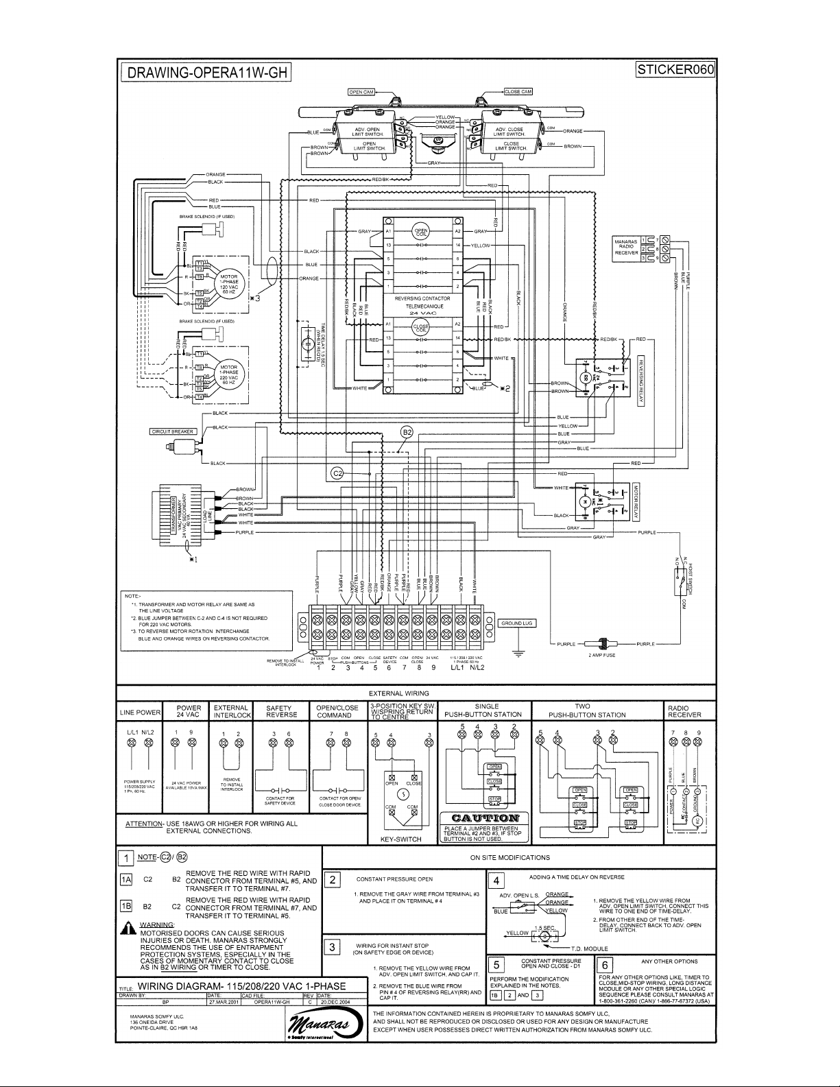
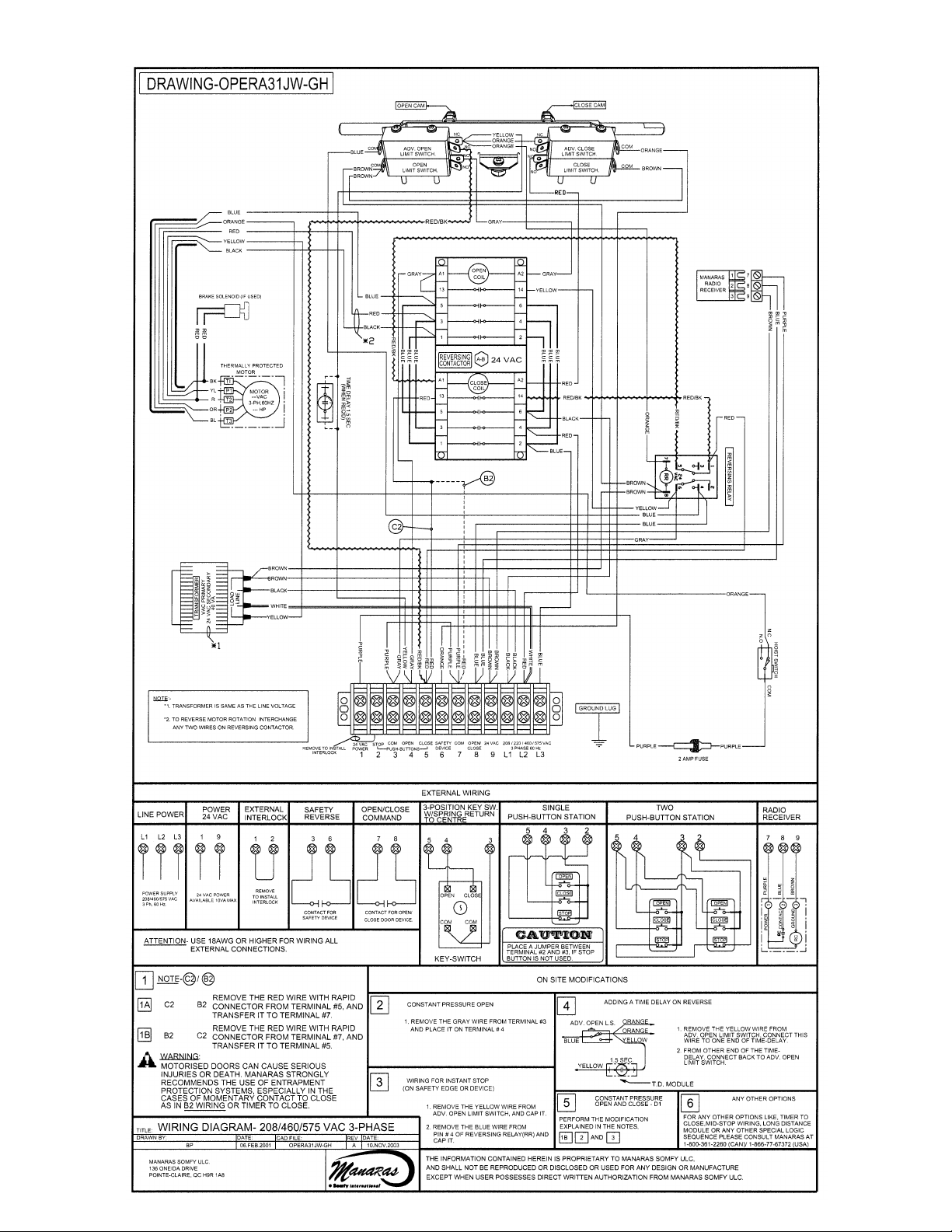
Refer to the electrical diagrams on pages 42 and 43 and the accessory wiring diagrams on page 36 and 37.
WARNING
EXERCISE CAUTION WHEN OPERATING MACHINE. THE DRIVE CHAIN AND LIMIT CHAIN, WHEN
EXPOSED AND TURNING COULD CAUSE SEVERE INJURY.
NOTE: Wiring diagrams are glued on the inside the control box cover. If the diagram is faded or damaged, call the
factory for a replacement. DO NOT INSTALL ANY WIRING OR ATTEMPT TO RUN THIS OPERATOR
WITHOUT CONSULTING THE WIRING DIAGRAM.
Main Power Supply
Power to the operator is of the permanent connection type. Connect according to local electrical code. Ground
the unit using the ground lug inside the control box.
IMPORTANT: Be aware of the dimension of the power supply cables pipe (BX for ex.) It must not limit the control
box movement to access the mechanical reduction parts. It is recommended to add 7 or 8 inches.
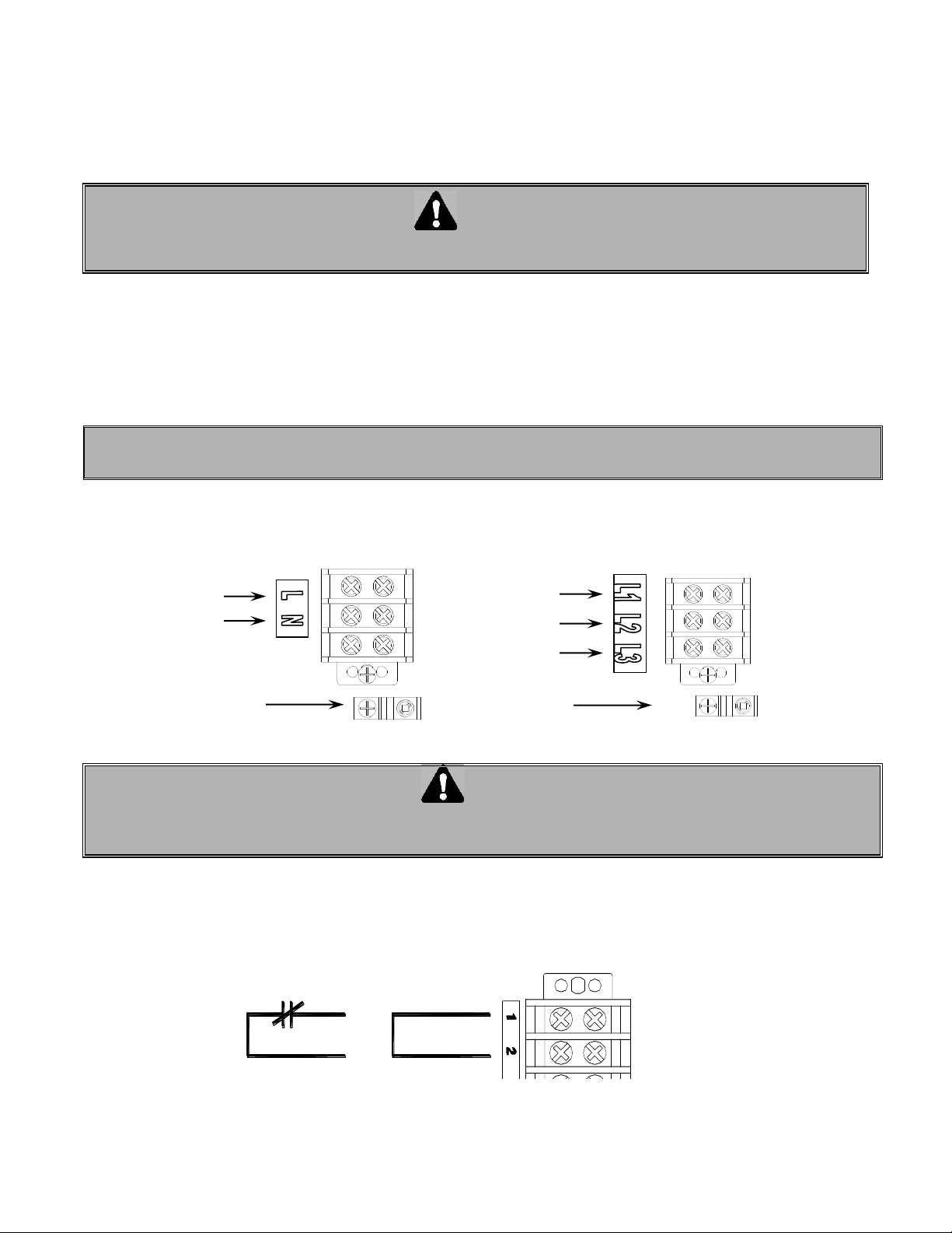
For single phase operators, connect the power supply to terminals L (line) and N (neutral) on the main terminal
strip.
For three phase operators, connect the power supply to terminals L1, L2 and L3 on the main terminal strip.
Figure 21 Power supply connection
WARNING
GROUND THE UNIT CORRECTLY USING THE COPPER GROUND LUG LOCATED INSIDE THE OPERATOR
CONTROL BOX.
Note: All other connections on the terminal strip (1 to 9) are low voltage class II 24 VAC.
1. External interlock between terminals 1 and 2. A jumper is factory installed between these two terminals. If
an external interlock is used (such as interlocking between two doors), remove the jumper between 1 and 2
and wire the interlock between these two terminals.
Figure 22 External interlock
Jumper
Interlock Device With
Normally Close Contact
Three phase
power
supply
Single
phase power
supply
Ground
Ground
Page 35
35
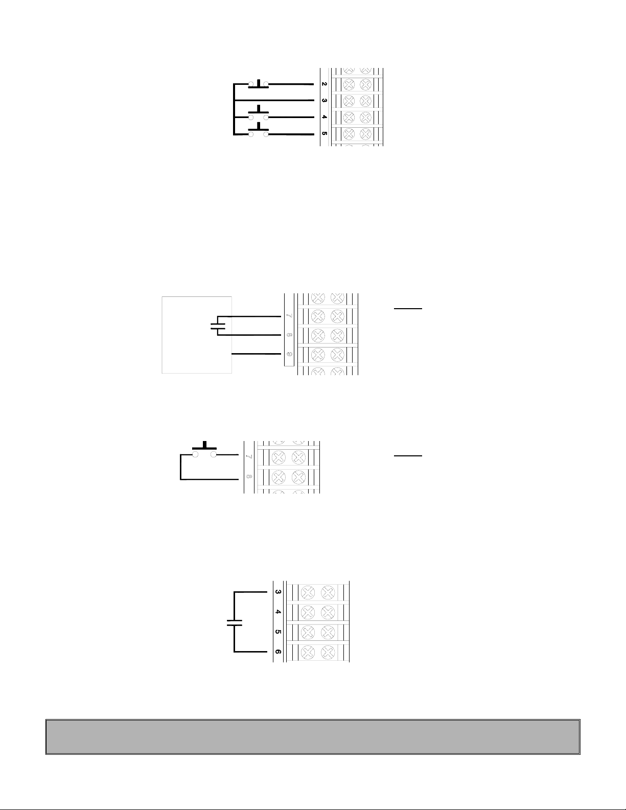
2. A 3 button push-button station (open/close/stop) can be wired to terminals 2, 3, 4 and 5. Two push-button
stations can be wired to these same terminals by following the wiring diagrams on pages 41 and 43.
Figure 23 Three button push-button station
3. Three terminals are provided for the wiring of a radio-control receiver. Terminal #9 is Ground, #7 is 24 VAC
(common) and #8 is the relay contact provided by the radio-control receiver to activate the door to open or
close. Furthermore, terminals 7, 8 and 9 are doubly available on the terminal strip inside and on a separate
small terminal strip located on the side of the unit. This terminal makes it convenient to wire-up a standard
single button radio receiver on the side of the unit. When the transmitter is activated, the door will open to
the fully open position. From the fully open position, the door will close. If transmitter is activated while
closing, the door will reverse to the fully open position.
NOTE: It may be required to reverse connections to 7 and 9 for other types or radio receivers (Allstar,
Linear, Pulsar ...).
Receiver
Figure 24 Radio-control
4. A single button open/close door device can be wired to terminals 7 and 8 to behave in the same way as the
radio control receiver.
Figure 25 Single button device
NOTE: If several control devices are to be used, connect one and check for proper operation before
connecting the next device.
5. A reversing edge can be wired up to terminals 3 and 6. These terminals can also be used for any other
reversing devices such as loop detectors and photocells.
Figure 26 Reversing edge or other device
IMPORTANT: Upon completion of all wiring connections, readjust limits as mentioned in section 8.6 using
"Open", "Close" and "Stop" buttons.
Stop
Open
Close
24 V a. c.
Contact
Ground
Normally open
contact
NOTE: (select B2)
Radio Control = B2 wiring
Momentary contact to open, close
and stop with a 3 buttons station.
NOTE: (select B2)
Open/Close = Radio Control
Momentary contact to open and close
with single button station.
Page 36
36
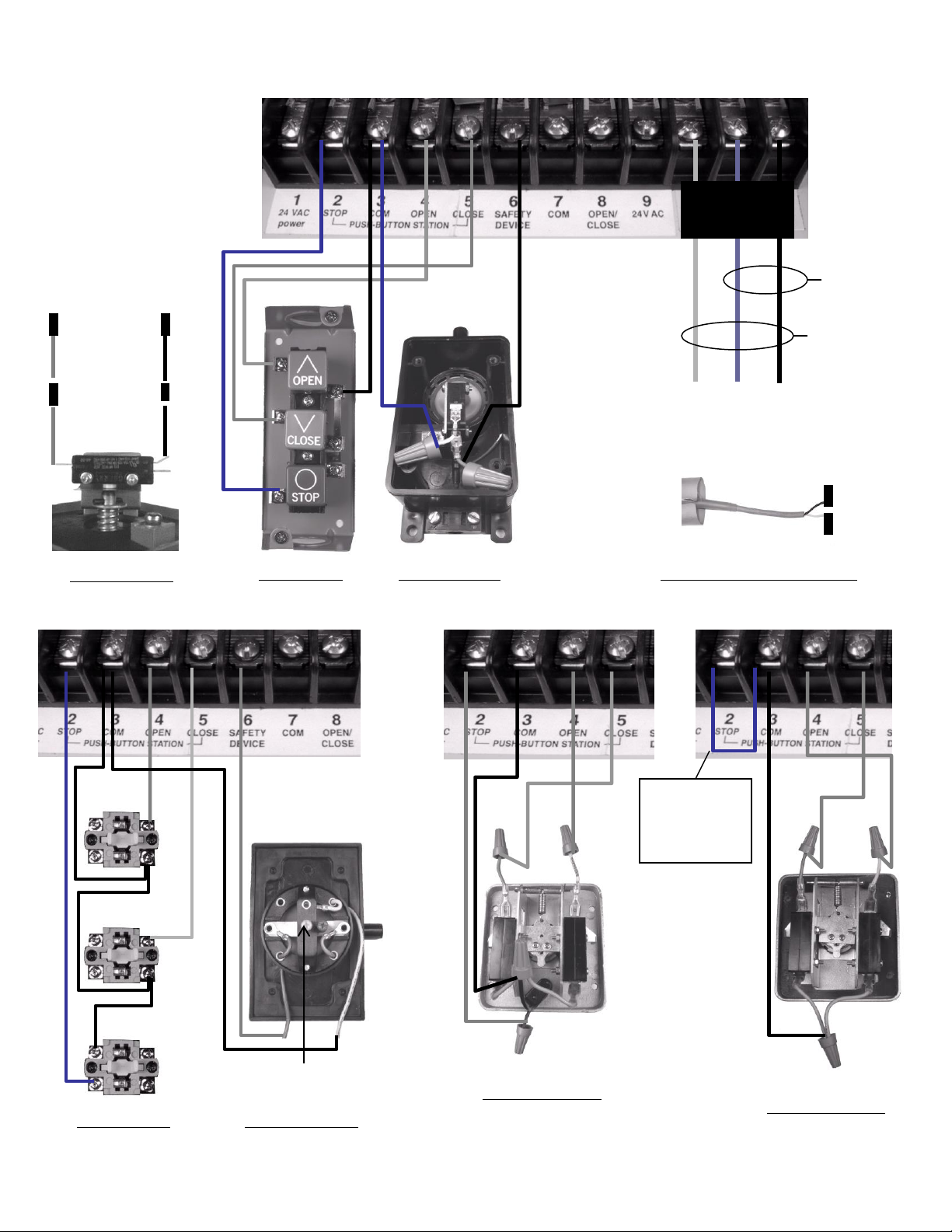
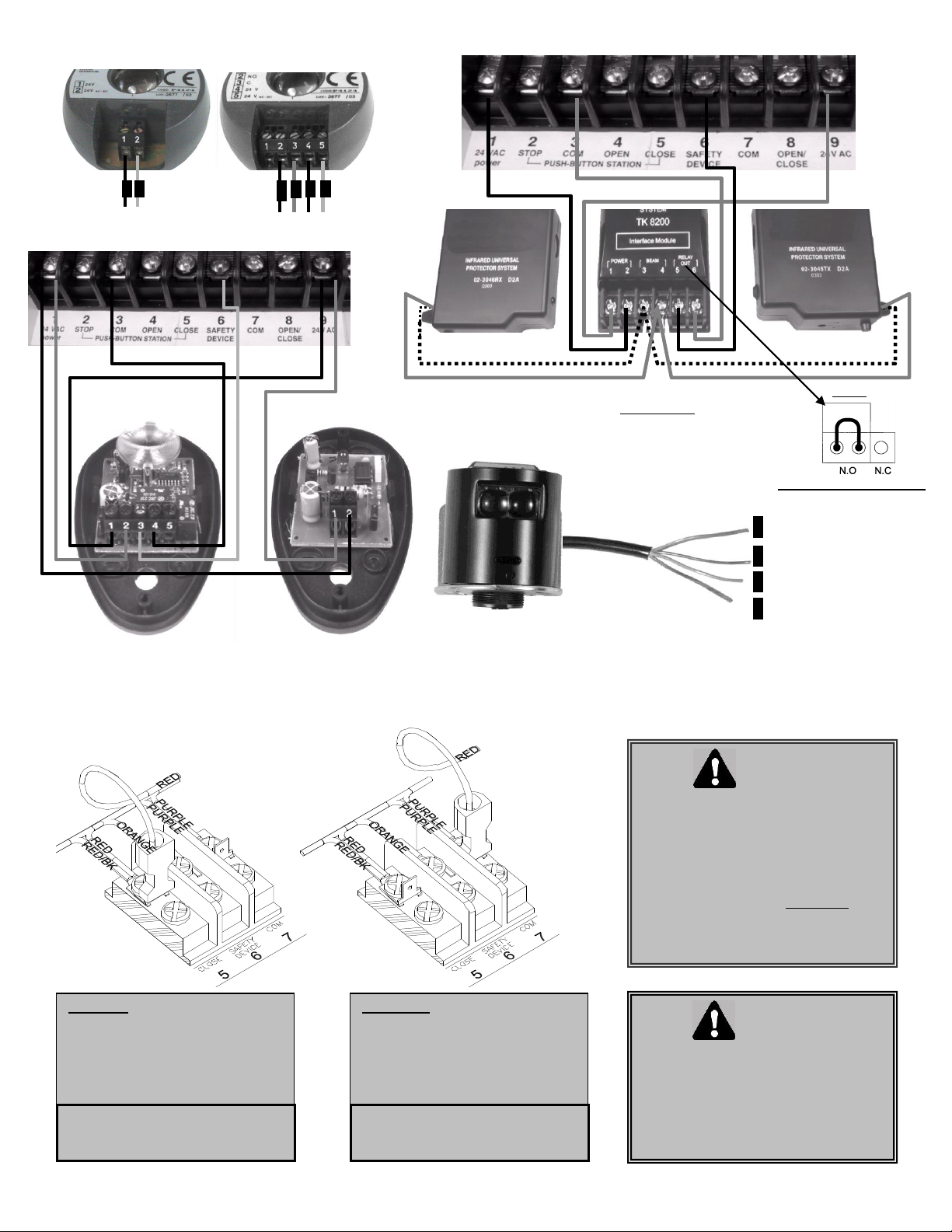
9.2 Accessory Wiring
3
6
STATION031
AIRSWITCH007
Jumper must
be removed if a
station with a
stop button is
also connected
PULLCORD003
KEYSWITCH019
STATION020
115/208/230
VAC
1 Ph. 60 Hz
208/230/
460/575 VAC
3 Ph. 60 Hz
Open
Close
Stop
Red
Yellow
NO
NC
NC
NO
NO
NC
Adjustment
7
Open/Close 8
Green
White
2-wire Electrical Sensing Edges
POWER
SUPPLY
AIRSWITCH009
3
Open only 4
KEYSWITCH015
Page 37
37
White
Brown
Blue
Orange
6
9
1
3
Interface Module Jumper
(TK8200)
Always set the jumper
located inside the
Interface Module on
N.O (Normally Open)
Black & White
White
Black & White
White
PHOTO038
PHOTO051
PHOTO008
FOR MOMENTARY CONTACT TO CLOSE (B2 WIRING), PLEASE REFER TO INSTRUCTION BELOW
3
6
PHOTO044
NOTE
WARNING
Wall control(s) must be located so
that the door is within sight of the
user.
If momentary contact (B2 mode) is
used, an external reversing device
must be install.
C2 wiring: momentary contact to open
and stop, constant pressure to close
with 3 push button station. Activation
of safety device will reverse the door
during closing. Auxiliary devices to
function as an open/control and to
reverse the door during closing.
B2 wiring: momentary contact to
open, close and stop with 3 push
button station. Activation of safety
device will reverse the door during
closing. Auxiliary devices to function
as an open/close control and to
reverse the door during closing.
C2 to B2
Move red wire from #5 to #7
B2 to C2
Move red wire from #7 to #5
WARNING
Motorized doors can cause serious
injuries or death. Manaras strongly
recommends the use of entrapment
protection systems, especially in
the case of momentary contact to
close such as with B2 wiring or
timer to close.
Page 38
38
9.4 CONNECTION OF A REVERSING EDGE DEVICE
IMPORTANT NOTE: If the door is controlled by any device other than a constant pressure push-button
station, a reversing edge must be connected.
CAUTION
Connect reversing device appropriate to installation.
Connection and installation of a reversing edge device is provided with the edge (Figure 28 and Figure 29). Any
such device that uses a normally open contact may be connected to terminals 3 and 6 on the low voltage terminal
block (Figure 26). When the door comes in contact with an object during downward travel, the circuit will cause
the motor to reverse the door to the fully open position. In addition, there is a cut-off limit switch (advanced close
limit switch) that will de-activate the reversing edge during the last few inches of the door's downward travel.
Figure 27 Reversing Edge
Figure 28 Reversing Edge
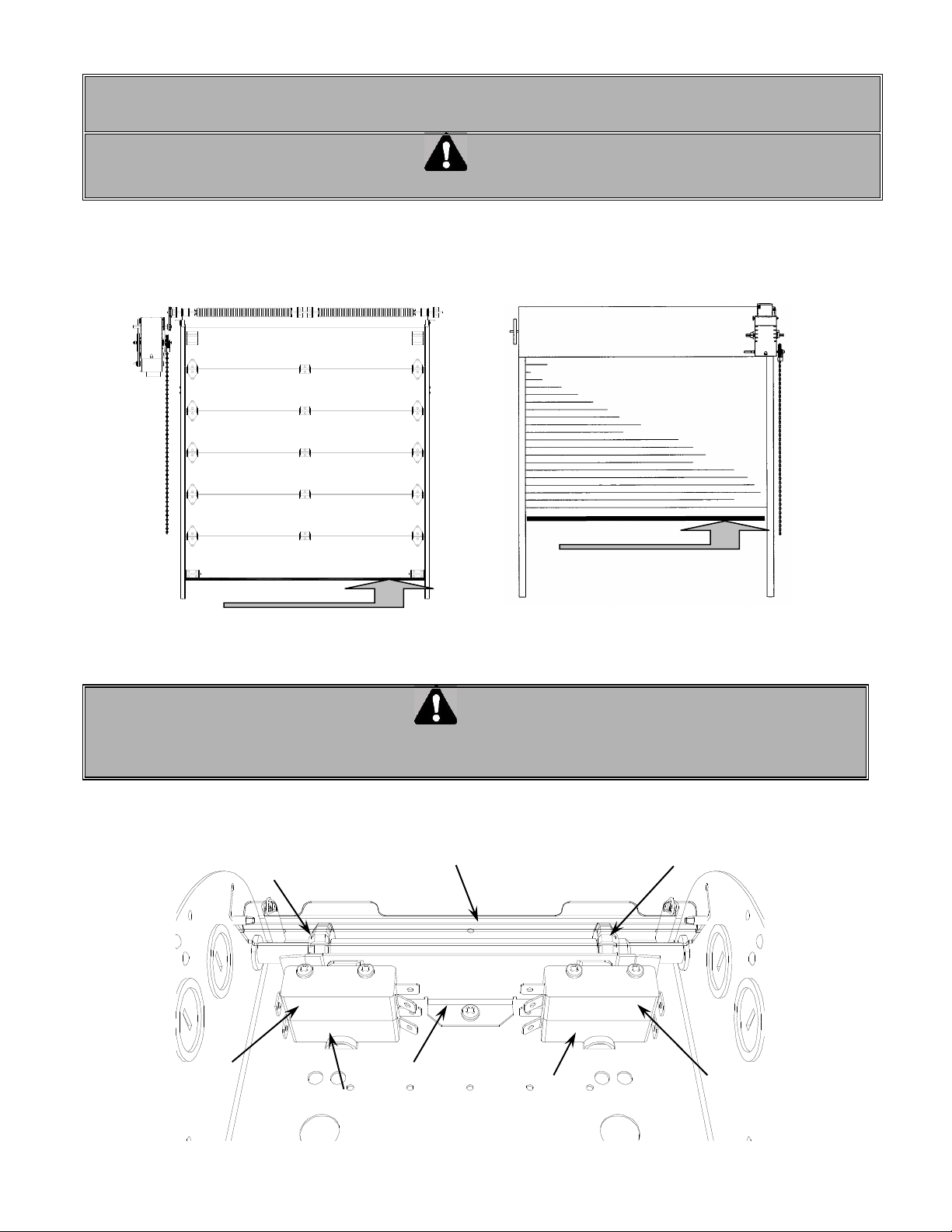
9.5 LIMIT SWITCHES
WARNING
TO AVOID THE DANGER OF POSSIBLE DAMAGE TO THE DOOR AND OPERATOR, TRAVELLING CAMS
MUST BE ADJUSTED TO THEIR APPROXIMATE POSITIONS BEFORE MANUALLY OPERATING THE
DOOR OR BEFORE APPLYING POWER TO THE OPERATOR.
There are 4 limit switches. Two are used as end of travel, one is for radio-control or one-button operation and one
is for reversing devices. These switches are activated by the rotary cams travelling on a threaded shaft (Figure 29).
Figure 29 Limit switches
Reversing edge
location
"Advanced Open"
limit switch
"Open" limit switch
"Advanced
Close" limit
switch
"Close" limit switch
"Open Position" cam
Cam retaining plate
"Close Position" cam
Limit switches lever
Reversing edge location
Reversing edge location
Page 39
39
9.6 DESCRIPTION LIMIT SWITCHES
The “Open” limit switch is the end of travel in the open position. Adjust the cam so that the door stops in
the open position at the desired location.
The “Advanced Open” limit switch is used for radio control (open/close) feature and to activate the timer
to close the door if a timer is used
The “Close” limit switch is the end in the close position. Adjust the cam so that the door stops in the
closed position at the desired position.
The “Advanced Closed” limit switch is used in the operation of the reversing edge or other reversing
devices. This limit switch prevents a signal from a reversing edge or device to reverse the door when it
is almost fully closed.
9.7 OPERATOR START-UP AND TESTING GUIDE
DANGER
WHILE PERFORMING THE TESTS LISTED BELOW, IT’S VERY IMPORTANT TO HAVE A POWER SHUT-OFF
DEVICE NEAR BY OR SOMEONE TO TURN THE POWER OFF WHEN NEEDED
This guide is a procedure you can follow to test every feature of your door operator.
If a 3 button push-button station is wired to the operator, disconnect it and then place a normally-closed contact
between terminals 2 and 3 to simulate a "Stop" push-button (use a spare limit switch or any such device).
Interrupting the power between these terminals will stop the operator.
Using a small wire jumper, momentarily jump (short-circuit) the following terminals:
A. Momentarily jump terminals 3 and 4.
The door will open instantly. Allow it open completely.
B. Momentarily jump terminals 3 and 5.
The door will close instantly. Allow it close completely.
C. Momentarily jump terminals 7 and 8.
The door will open instantly. Allow it to open completely.
D. Momentarily jump terminals 7 and 8.
The door will close instantly. While closing, go to step E.
E. Momentarily jump terminals 7 and 8 again.
The door will reverse to open. Allow it to open completely.
F. Momentarily jump terminals 7 and 8.
The door will close. While closing, go to step G.
G. Momentarily jump terminals 3 and 6.
The door will reverse to open. Allow it to open completely.
H. Momentarily jump terminals 7 and 8 again.
The door will close. Allow it to close completely.
I. Momentarily jump terminals 3 and 6.
The door should remain still.
This procedure can be repeated using the radio-control terminal strip located on the outside of the control box by
using terminals "24VAC" and "CONTACT" instead of terminals 7 and 8.
9.8 TROUBLE-SHOOTING GUIDE
All operators are thoroughly tested and adjusted before shipping. In most cases, it is after installation and hook-up
to external devices that a problem will arise.
If after connecting external devices to the operator, you encounter problems, the trouble often lies in the external
devices or in the wiring leading to the external devices. Verify all external wiring making certain that there are no
wires pinched anywhere shorting to ground and that there are no voltages being sent into the control circuit. The
operator functions ONLY with dry contacts: all voltages necessary for proper functioning are generated by the
operator transformer.
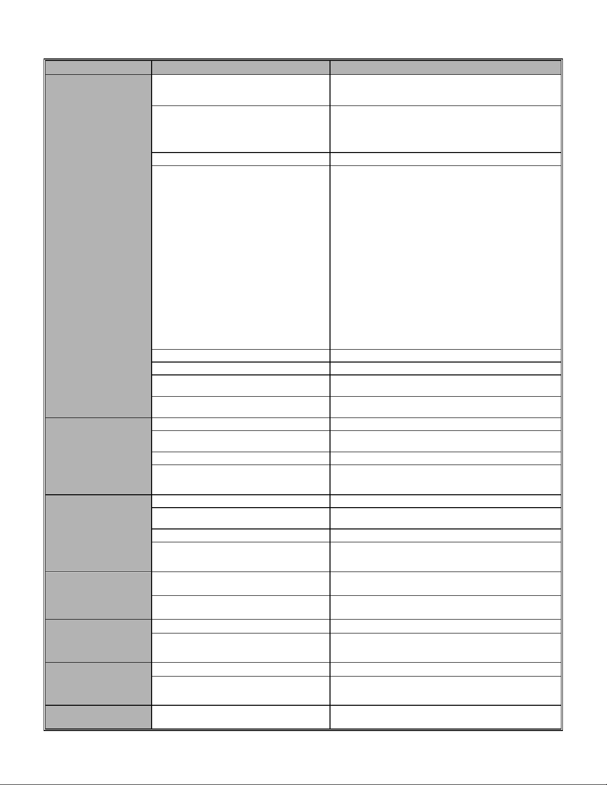
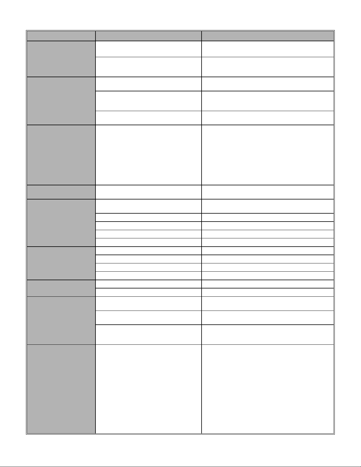
The following trouble-shooting guide (TABLE 3) will help you identify the source of the problem given a
particular symptom.
Page 40
40
TABLE 3 TROUBLE-SHOOTING GUIDE
SYMPTOM
PROBABLE CAUSE
SUGGESTED ACTION
Door will not
respond to “open”
or “close” push-
button.
Chain hoist is engaged which
activated the disconnect switch
Pull on chain slightly in each direction in order to
disengage the chain hoist and return the operator
to electrical operation. Check switch otherwise.
Motor has overworked and the
overload thermal protection has
tripped.
Reset the overload protection: press reset button
located on the side of the unit for a single phase
operator. For a three phase operator, the thermal
switch is inside the motor, let motor cool and
restart operator. Is the door unbalanced?
Circuit breaker tripped (if used).
Reset circuit breaker.
Fuse is blown.
Replace fuse. If control circuit fuse keeps blowing:
Disconnect all external devices. Leave power
terminals connected. Run the operator artificially
by using jumpers and shorting out the appropriate
terminals as indicated in the Start-Up and Testing
Guide. Then reconnect the various external
devices one by one until you find the one causing
the short to ground.
OR: If you have an ohm-meter, use it to check all
incoming wires for continuity to ground. The meter
should read infinity in all instances. If there is
conduction between any control circuit wire and
ground, this indicates a leak to ground and this is
why the control circuit fuse blows when power is
applied.
In some cases, the trouble is intermittent: i.e. the
fuse only blows at certain times. This problem is
more difficult to detect, but again: disconnect all
wires going to external devices, and run the
operator: if the fuse does not blow, this indicates
that the trouble resides outside the operator.
Transformer defective.
Replace.
Defective "stop" push-button.
Replace.
Loose connection in one of the pushbuttons.
Verify, tighten or replace.
Defective "open" or "close" pushbutton.
Replace.
Door will not
respond to "open"
command, but will
respond to "close"
command.
Defective "open" push-button.
Replace.
"Open" cam has been overdriven.
Reinsert cam back onto the threaded shaft and
readjust Open position.
Defective "open" limit switch.
Replace
Loose wire on "open" push-button,
"open" limit switch or coil of open
contactor.
Verify, tighten or replace.
Door will not
respond to "close"
command, but will
respond to "open"
command.
Defective "close" push-button.
Replace.
"Close" cam has been overdriven.
Reinsert cam back onto the threaded shaft and
readjust Close position.
Defective “close” limit switch .
Adjust.
Loose wire on close push-button,
close limit switch or coil of close
contactor.
Verify, tighten or replace.
Door moves in
wrong direction.
Incorrect phasing on a three phase
operator.
Interchange any two power leads.
Wrongly connected on a single phase
operator.
Interchange Black and White motor leads on
contactor.
Door closes and
operator does not
shut-off at the end
of closing travel.
"close" contactor is defective.
Verify and replace.
"close" limit switch defective
Verify and replace.
Door opens and
operator does not
shut-off at the end
of opening travel.
"open" contactor is defective.
Verify and replace.
"open" limit switch is defective.
Verify and replace.
Sensing edge does
not reverse door.
Pneumatic hose broken, electrical
wiring not connected.
Contact a qualified installer.
Page 41
41
SYMPTOM
PROBABLE CAUSE
SUGGESTED ACTION
Reversing devices
will open the door
when the door is
closed.
The advanced close limit switch is
defective.
Replace.
The advanced close limit switch is not
being engaged by travelling cam.
The advanced close limit switch needs to be
adjusted just slightly ahead of the end of travel
Close limit switch.
When door closes it
reverses to fully open
after it hits the floor.
The advanced close limit switch is
defective.
Replace.
The advanced close limit switch is not
being engaged by travelling cam.
The advanced close limit switch needs to be
adjusted just slightly ahead of the end of travel
Close limit switch.
A "Close" command is being given.
Check "Close" push-button or any closing
device for short-circuit.
Radio-control does
not function or
hesitates for 10
seconds before
working.
It is normal for a radio receiver to take
up to 10 seconds to "warm-up" before
being fully operational. Therefore,
when applying power for the first
time, the radio-control will take 10
seconds before becoming fully
operational.
Check protocol code pins of the transmitter and
receiver: they must be the same. Press on the
transmitter and listen to the receiver: you should
hear a faint click. The transmitter battery may
be dead or your receiver may need servicing.
To test for radio-control function, short out
momentarily terminals 7 and 8 on the terminal
strip. Operator should function normally. Have
the radio-control verified: the mini-relay inside
the receiver may be defective.
Motor hums, starts
when spun.
Capacitor defective. (single phase
only)
Replace
Motor fails to shut off
at fully closed or
opened positions.
Defective limit switch.
Operate limit switch manually while door is
moving. If door does not stop, replace switch.
Limit cams are not adjusted.
Verify and adjust.
Limit drive chain broken.
Replace.
Loose sprocket on limit shaft.
Tighten set screw.
Limit shaft does not rotate.
Verify and replace accordingly.
Motor turns but door
does not move.
Sprocket key is missing.
Replace.
Drive chain is broken.
Replace.
One of the reduction chains is broken
Replace.
Clutch is slipping.
Adjust clutch tension.
Motor hums or does
not run.
Door locked or jammed.
Verify manual operation of door.
Dead phase (three phase supply).
Check power supply, fuses on each phase.
Limit switches do not
hold their setting.
Loose drive or limit chain allows chain
to jump sprocket teeth.
Adjust chain to proper tension
Limit cam retainer not engaging slots
in limit cams.
Be sure retainer is in slots of BOTH cams.
Limit cams are binding on shaft
threads which allows them to jump
position on retainer.
Lubricate shaft threads. Limit cams should turn
freely.
Radio-control opens
and reverses the
door, but when the
door is fully opened,
will close the door a
little and bounce
back to the open
position again. Door
cannot be closed
except by the "close"
push-button.
The Advanced Open limit switch is
insufficiently advanced from the full
Open limit switch. The contact of the
radio-control receiver is maintained
for 1.5 seconds when a command is
issued by the radio transmitter.
Therefore, when the door is fully
opened, and a pulse is sent from the
transmitter, the receiver maintains the
contact closed for 1.5 seconds. If the
door has closed and the Advanced
Open limit switch has returned to its
normal state, the reversing relay will
be activated, and the door bounces
back to the open position.
Adjust the Advanced Open limit switch by
bending the limit switch lever punch away from
the travelling cam and more towards the Open
limit switch.
Page 42
42
9.9 Single phase Hardwired wiring
Page 43
43
9.10 3-phase Hardwired wiring
Page 44

44
Manaras warrants its operators to be free from defects in material and workmanship under normal
and proper use for a period of two years from date of invoice. Mechanical, electrical and electronic
accessories are warranted for one year from date of invoice. Wearing parts such as clutch pads,
v-belts, and brake bands are excluded from warranty.
Manaras’ only obligation shall be to repair or replace defective equipment which does not conform
to the warranty. Manaras shall not be liable for any injury, loss or damage, direct or consequential,
arising out of the inability to use the equipment. Before using, Buyer and/or the ultimate User shall
determine the suitability of the product for its intended use, and User assumes all risks and liability
in connection therewith. The foregoing may not be changed except by an Agreement signed by an
authorized representative of Manaras.
The articles that are replaced pursuant to the terms of this warranty shall be retained by Manaras,
and the User is responsible for any freight costs relating to repair or replacement.
The foregoing warranty is exclusive and in lieu of all other warranties of quality, whether written,
oral or implied (including any other warranty of merchantability or fitness for purpose).
The following are exclusions from warranty:
• If usage, product modification, adaptation or installation are not in accordance with our
installation and operating instructions.
• If the product has been opened, dismantled or returned with clear evidence of abuse or other
damage.
• If our written specifications are not properly applied by the Buyer when selecting the
equipment.
• If our written instructions for installation and wiring of the electrical connections have not been
followed.
• If our equipment has been used to perform functions other than the functions it was designed
to handle.
• If Manaras equipment is used with electrical accessories (switches, relays, etc.) that have not
been previously approved in writing by the Manaras Engineering Department.
• If electrical accessories and other components have been used in disregard of the basic
wiring diagram for which they were designed.
All costs related to installation and reinstallation of the Manaras equipment covered by this
warranty are not the responsibility of Manaras. Manaras will not be responsible for any
consequential damages during the following installation procedures. If the Buyer resells any
Manaras products to another Buyer or End-user, it shall include all of the terms and provisions of
this warranty in such resale. Manaras’ responsibility to any such Third Party shall be no greater
than Manaras’ responsibility under the warranty to the original Buyer.
Returns
No returns will be accepted without prior written authorization by Manaras. All returns must be
accompanied by a Return Authorization Number issued by Manaras, and all unauthorized returns
will be refused. The return shipment is to be freight prepaid by the Buyer, and under no
circumstances shall the Buyer deduct the value of the returned merchandise from any remittance
due. A restocking fee of 15% of Manaras sale price will be charged.
WARRANTY
Page 45

45
NOTES
Page 46

46
NOTES
Page 47

47
NOTES
Page 48

48
BOOK146 REV 1 – 2007/02/19
 Loading...