

Manaras Opera-H, Opera-J, Opera-SH, Opera-HJ, OPH Installation Manual
...
Installation & Instruction Manual
Installation & Instruction Manual
Commercial & Industrial Heavy Duty Jackshaft Operator
Commercial & Industrial Heavy Duty Jackshaft Operator
(For sectional doors, rolling doors and grilles)
(For sectional doors, rolling doors and grilles)
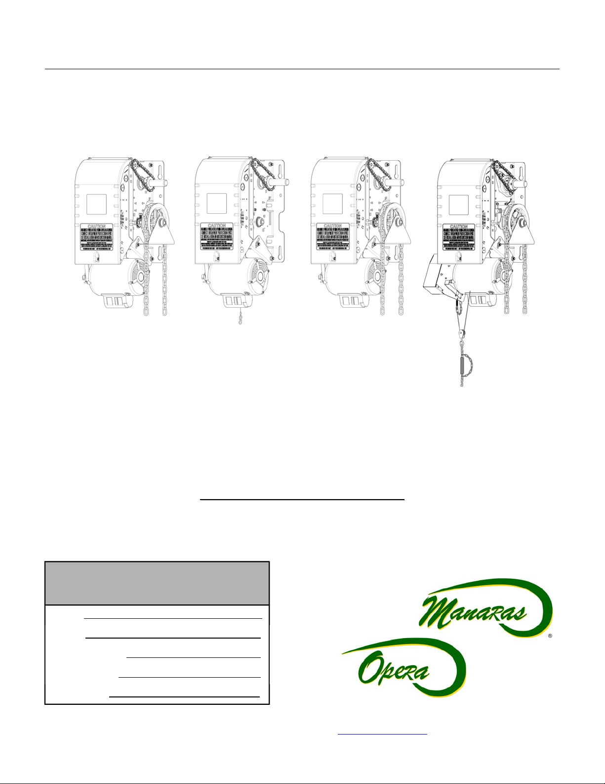
Opera-H
Opera-H
(OPH)
(OPH)
READ AND FOLLOW ALL INSTRUCTIONS.
SAVE THESE INSTRUCTIONS.
GIVE TO END-USER.
Serial #
Model #
Wiring Diagram #
Project #/Name
Opera-J
Opera-J
(OPJ)
(OPJ)
Electro-Mechanical Control
Electro-Mechanical Control
Opera-HJ
Opera-HJ
(OHJ)
(OHJ)
Opera-SH
Opera-SH
(OSH)
(OSH)
Door #/Name
For technical support, please call 1-800-361-2260 or visit www.manaras.com for more information

2
TABLE OF CONTENTS
Installation Instructions............................................................................................................................................... 3
1 General Specifications and Dimensions (OPH / OPJ / OHJ)..............................................................................................................................4
2 General Specifications and Dimensions (OSH)...................................................................................................................................................5
3 Door & Operator Hardware..................................................................................................................................................................................6
3.1 Delivery of Operator..................................................................................................................................................................................6
3.2 Hardware Supplied....................................................................................................................................................................................6
4 Operator Installation.............................................................................................................................................................................................7
4.1 Operator Mounting Options.......................................................................................................................................................................7
4.2 Operator Mounting Holes..........................................................................................................................................................................7
4.3 Sprockets, Spreader Bar and Drive Chain Installation.............................................................................................................................8
5 Operator Control Box...........................................................................................................................................................................................9
6 Manual Hand Chain and Disconnect Chain.......................................................................................................................................................10
6.1 Installation...............................................................................................................................................................................................10
6.2 Operating Mode.......................................................................................................................................................................................11
7 Limit Switches & Limit Cams: Adjustment & Functionality.................................................................................................................................13
7.1 Limit Switch Functionality........................................................................................................................................................................13
7.2 Limit Switch Adjustments: Open and Close Cam Settings.....................................................................................................................13
7.3 Advanced Limit Switch Adjustments.......................................................................................................................................................13
7.4 Limit Switch Adjustment Using Manual Hand Chain (if applicable)........................................................................................................14
7.5 Limit Switch Adjustment Without Manual Hand Chain (if applicable).....................................................................................................14
8 Electrical Wiring.................................................................................................................................................................................................15
8.1 Low Voltage (Controls) and High Voltage (Power) Connections............................................................................................................16
8.2 Main Power Supply Connection..............................................................................................................................................................16
8.3 Wall-Button Connection...........................................................................................................................................................................17
8.4 Optional Accessory Connections............................................................................................................................................................18
9 Operator Start-up...............................................................................................................................................................................................22
10 Clutch Adjustment..............................................................................................................................................................................................23
11 Electromechanical Circuit Programming (Contactor Circuit).............................................................................................................................24
11.1 Run Mode Settings..................................................................................................................................................................................24
11.2 On Site Modifications..............................................................................................................................................................................25
User Instructions........................................................................................................................................................ 26
1 Quick Fix Instructions.........................................................................................................................................................................................27
Maintenance Instructions........................................................................................................................................... 28
1 Preventative Maintenance Schedule.................................................................................................................................................................28
1.1 Mechanical Inspection.............................................................................................................................................................................28
1.2 Electrical Inspection................................................................................................................................................................................29
1.3 Band Brake Maintenance........................................................................................................................................................................30
2 Troubleshooting Guide.......................................................................................................................................................................................32
3 Electrical Drawings.............................................................................................................................................................................................34
3.1 1 Phase Operator – Hardwired Wiring....................................................................................................................................................34
3.2 3 Phase Operator – Hardwired Wiring....................................................................................................................................................35
3.3 External Wiring – Hardwired...................................................................................................................................................................36
4 Mechanical Exploded Views and Replacement Components...........................................................................................................................37
4.1 Opera Heavy-Duty Jackshaft General View...........................................................................................................................................37
4.2 Opera-H...................................................................................................................................................................................................38
4.3 Opera-J...................................................................................................................................................................................................39
4.4 Opera-HJ.................................................................................................................................................................................................40
4.5 Opera-SH................................................................................................................................................................................................41
4.6 Opera Brake (BRAKE 013).....................................................................................................................................................................42
4.7 Opera Control Box - Hardwired...............................................................................................................................................................43
4.8 Replacement Motors, Transformers, Solenoids, Relays and Resets.....................................................................................................44
Notes............................................................................................................................................................................ 45
Warranty...................................................................................................................................................................... 47
For technical support, please call 1-800-361-2260 or visit www.manaras.com for more information

3
Installation Instructions
IMPORTANT INSTALLATION INSTRUCTIONS
WARNING
TO REDUCE THE RISK OF SEVERE INJURY OR
DEATH TO PERSONS:
1. READ AND FOLLOW ALL INSTALLATION INSTRUCTIONS.
2. Install only on a properly operating and balanced door. A door that is operating
improperly could cause severe injury. Have qualified service personnel make repairs
to cables, spring assemblies and other hardware before installing the operator.
3. Remove all pull ropes and remove, or make inoperative, all locks (unless
mechanically and/or electrically interlocked to the power unit) that are connected to
the door before installing the operator.
4. Installation of this door operator must be done by a qualified installer.
5. Verify that the operator is correct for type, size of door and frequency of use per the
operator specifications.
6. Install the door operator at least 8 feet (2,44 m) or more above the floor if the operator
has exposed moving parts. Covers or guarding, provided by the manufacturer, must
be installed when the operator is mounted less than 8 feet (2,44 m) above the floor.
7. Do not connect the door operator to the source of power until instructed to do so.
8. Locate the control station: (a) within sight of the door, (b) at a minimum height of
5 feet (1,5 m) above floors, landings, steps or any other adjacent walking surface so
small children cannot reach it, and (c) away from all moving parts of the door.
9. Install the Entrapment Warning Placard next to the control station in a prominent
location.
10. For products having a manual release, instruct the end user on the operation of the
manual release.
11. If you have any questions about the safety of the door operating system, do not install
the operator, contact Manaras-Opera at 1-800-361-2260.
For technical support, please call 1-800-361-2260 or visit www.manaras.com for more information
4
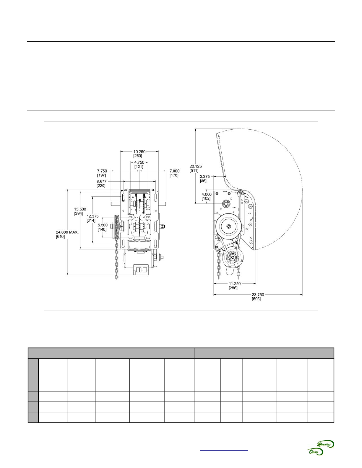
1 General Specifications and Dimensions (OPH / OPJ / OHJ)
SUPPLY VOLTAGE...............................115, 230 VAC single-phase, 208, 460, 575 VAC three-phase
CONTROL VOLTAGE............................24 VAC class 2 transformer, 2 amp fuse type ACG
MOTOR.................................................Continuous duty 1/2, 3/4, 1 horsepower
OPERATOR OUTPUT SPEED..............41 RPM
NET WEIGHT (Operator only)...............86 Lbs (39 Kg) for 1/2HP 115V Opera-H model
STANDARD WIRING TYPE..................C2 (momentary contact to open/stop and constant-pressure-to-close)
APPLICATION.......................................Heavy duty for sectional doors, rolling doors and grilles
DUTY.....................................................25 cycles/hour or 100 cycles/day maximum
Figure 1 - Opera-H, Opera-J and Opera-HJ Dimensions
Table 1 - Operator Selection Guide (OPH / OPJ / OHJ)
Maximum Area in Square Feet (general guideline)
Rolling Doors Sectional Doors
Insulated
HP
Steel
½ 157 236 260 319 358 196 245 314 343 392
¾ 206 294 358 451 515 270 319 441 490 549
1 255 358 446 574 613 294 392 490 564 613
16 ga
Steel
For technical support, please call 1-800-361-2260 or visit www.manaras.com for more information
Steel Grilles
20 ga
Steel
Alu. Door
22 ga Steel
Alu. Grilles
24 ga
Steel
Steel
18 ga
ins.
Steel
18 ga
20 ga
ins.
Wood
Steel 20 ga,
22 & 24 ga
ins.
Alu. Steel
22 & 24 ga
Fiber
Glass
5
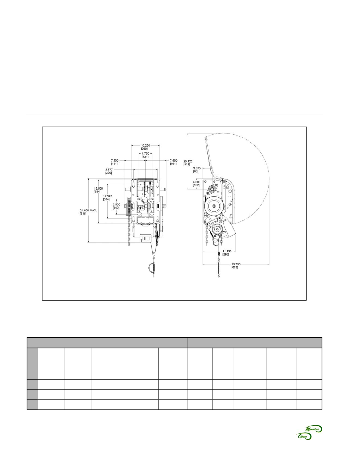
2 General Specifications and Dimensions (OSH)
SUPPLY VOLTAGE...............................115, 230 VAC single-phase, 208, 460, 575 VAC three-phase
CONTROL VOLTAGE............................24 VAC class 2 transformer, 2 amp fuse type ACG
MOTOR.................................................Continuous duty 1/2, 3/4, 1 horsepower
OPERATOR OUTPUT SPEED..............41 RPM
NET WEIGHT (Operator only)...............96 Lbs (44 Kg)
STANDARD WIRING TYPE..................C2 (momentary contact to open/stop and constant-pressure-to-close)
APPLICATION.......................................Ultra high-end heavy duty v-belt drive for sectional doors, rolling doors and
grilles
DUTY.....................................................25 cycles/hour or >100 cycles/day
Figure 2 - Opera-SH Dimensions
Table 2 - Operator Selection Guide (OSH)
Maximum Area in Square Feet (general guideline)
Rolling Doors Sectional Doors
Insulated
HP
Steel
½ 157 236 260 319 358 196 245 314 343 392
¾ 206 294 358 451 515 270 319 441 490 549
1 255 358 446 574 613 294 392 490 564 613
16 ga
Steel
For technical support, please call 1-800-361-2260 or visit www.manaras.com for more information
Steel Grilles
20 ga
Steel
Alu. Door
22 ga Steel
Alu. Grilles
24 ga
Steel
Steel
18 ga
ins.
Steel
18 ga
20 ga
ins.
Wood
Steel 20 ga,
22 & 24 ga
ins.
Alu. Steel
22 & 24 ga
Fiber
Glass
6
3 Door & Operator Hardware
3.1 Delivery of Operator
Upon delivery of your OPERA jackshaft operator, inspect the unit immediately for any shipping damages. Verify that
you have received all the hardware parts pertaining to your operator model, as listed in Table 3 and shown in
Figure 3. If ordered, other items such as radio controls or other types of optional equipment may be present. If any
item is missing or if there is evidence of damage, call the transport company or your direct supplier.
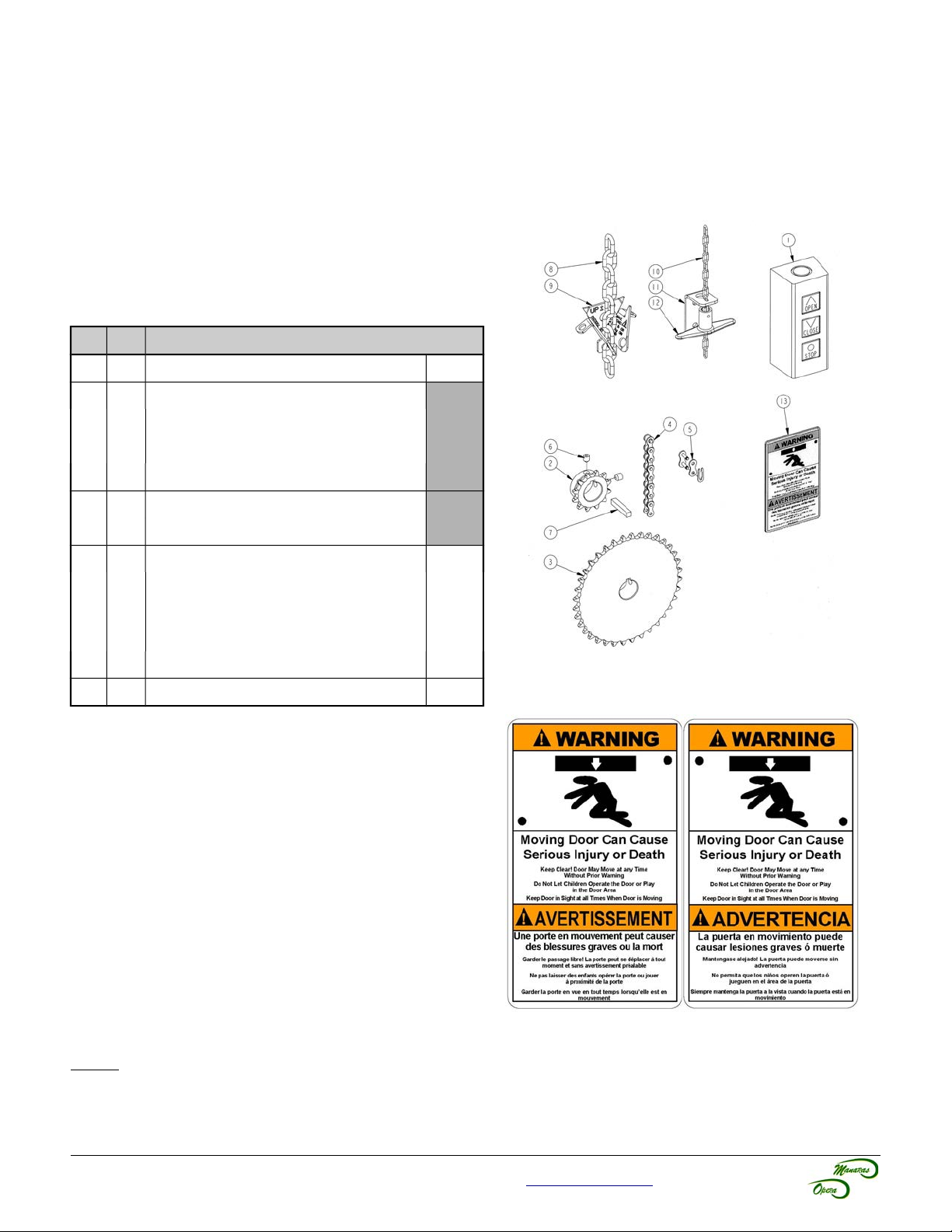
3.2 Hardware Supplied
Table 3 - Standard Hardware Parts Supplied
No Qty Description
1 1 3-Push-button station (open/close/stop)
2 1 Operator sprocket
3 1 Door sprocket
4 1 #41/#50 Drive chain, 4ft
5 1 #41/#50 Chain link
(1)
(1)
(1) (2)
(1)
Lxxxx
Hxxxx
Gxxxx
6 4 5/16-18 x 5/16” Set screw
7 2 Key 1/4” x 1-1/2”
8 1 Pocket wheel hand chain, 24ft
9 1 Chain keeper for hand chain
10 1 Disconnect chain, 14ft
(3) (4)
(4)
(3) (5)
11 1 Chain keeper for disconnect chain
12 1 Handle for disconnect chain
(5)
13 1 Entrapment Warning Placard
(1) Differs according to operator model and door characteristics
(2) 5ft for 42/54/60 tooth door sprocket, 8ft for 72 tooth door sprocket
(3) Quantity = 2 times door shaft height minus 4ft
(4) Only supplied with OMH/OPH/OHJ/OBH/OSH/OGH/MGH/GH
(5) Only supplied with OMJ/OPJ/OSH/MGH/GH
HD1HBAG
(5)
Figure 3 - Standard Jackshaft Hardware
Figure 4 - Entrapment Warning Placard
NOTE: Install the Entrapment Warning Placard (shown in Figure 4), next to the control station, visible in the area of
the door.
For technical support, please call 1-800-361-2260 or visit www.manaras.com for more information
7
4 Operator Installation
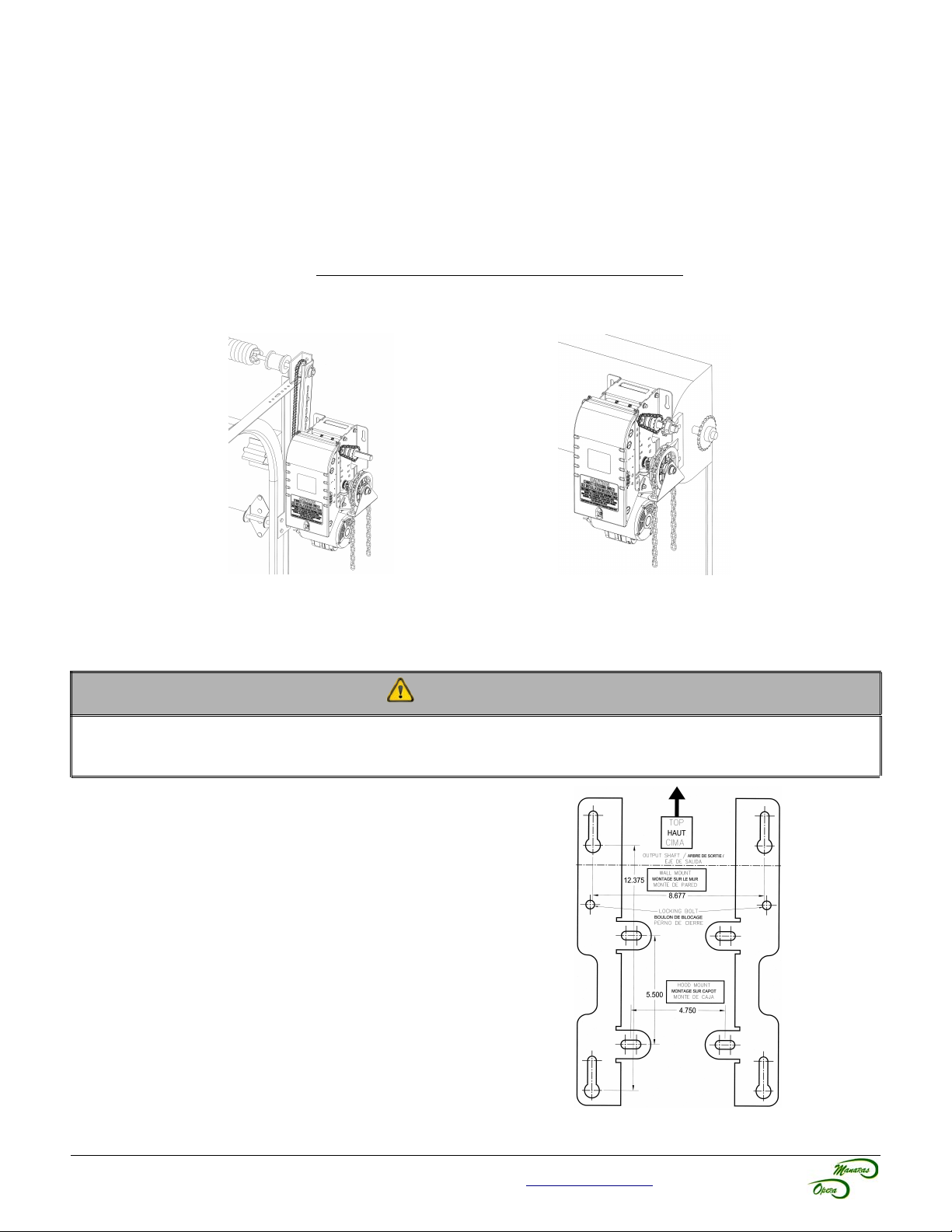
4.1 Operator Mounting Options
The jackshaft operator line has a dual output shaft. These operators may be wall-mounted on either the left hand side
or the right hand side of a sectional door. They can also be hood-mounted, using BRACKET111 (sold separately), or
shelf-mounted on either side of the door.
The standard jackshaft hoist model comes with a chain hoist located on the right of the operator. If the application
requires that the chain hoist be located on the left of the operator (ex: rolling doors, left operator hood mounting), it
must be requested at time of order. Do not attempt to modify the chain hoist yourself.
This operator is not intended to be installed on horizontal slide doors.
Figure 5 - Right Side Wall Mount
(Chain Hoist on Right)
Figure 6 - Right Side Hood Mount with
BRACKET111 (Chain Hoist on Right)
4.2 Operator Mounting Holes
CAUTION
The operator has exposed moving parts and to prevent access to the pinch points, the operator must be installed
at least 8 feet (2,44 m) or more above the floor. Alternatively, covers or guarding, provided by the manufacturer,
must be installed when the operator is mounted less than 8 feet (2,44 m) above the floor.
1. Ensure that the wall or mounting surface provides
adequate support for the operator. The surface must be
rigid enough to prevent any play between the operator
and door shaft. Manaras-Opera recommends the use of
BRACKET111 for hood-mount application.
2. Locate the four mounting holes, as shown in Figure 7.
3. The optimum distance between the door shaft and the
operator drive shaft is between 12" and 15".
4. Secure BRACKET111 to the end bracket of the rolling
door or mount the operator to the wall with 3/8" thrubolts. If the wall construction prohibits the use of thrubolts, then appropriate and sufficiently sized lag bolts
and anchors may be used.
5. Only tighten the bolts after having adjusted tension of
the drive chain, as shown in section 4.3, p.8.
6. Ensure that the door and operator shafts are parallel.
Figure 7 - Opera Mounting Holes
For technical support, please call 1-800-361-2260 or visit www.manaras.com for more information
8
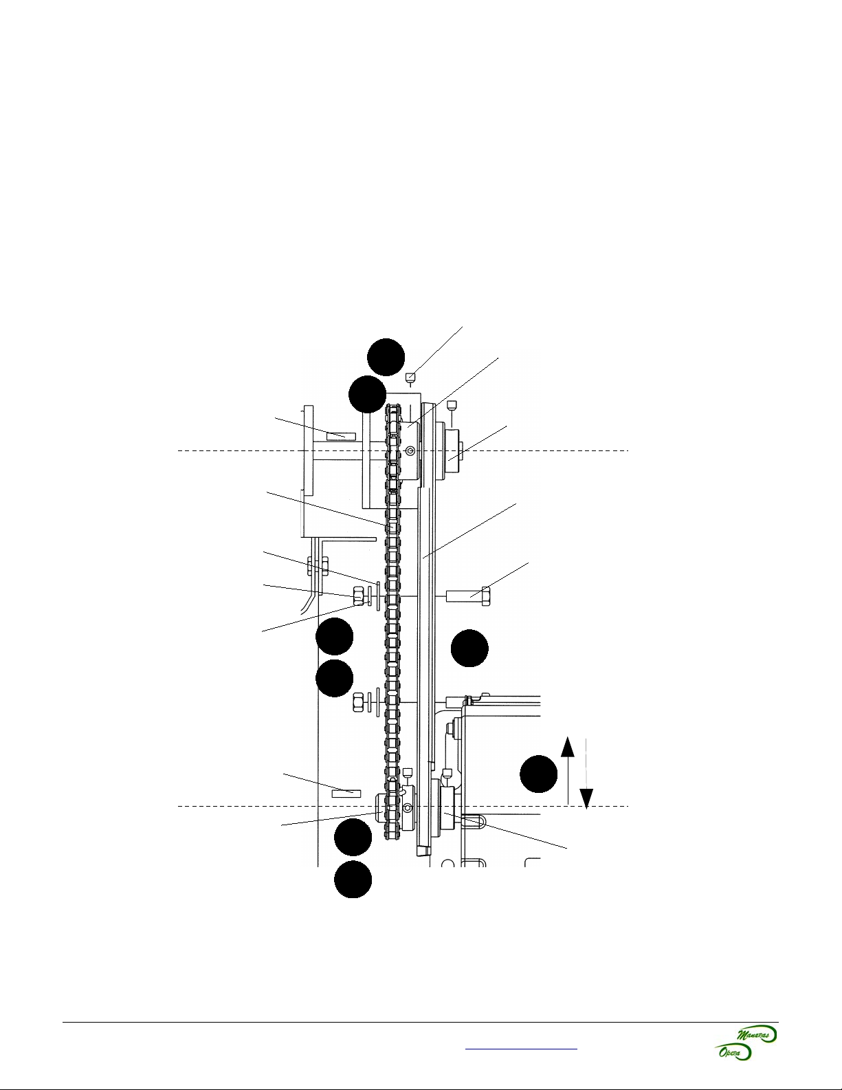
4.3 Sprockets, Spreader Bar and Drive Chain Installation
The hardware components shown in Figure 8 have been supplied with your operator.
1. Place the door sprocket loosely on the door shaft.
2. Place the operator drive sprocket on the appropriate side of the operator and align it with the drive sprocket of
the operator.
3. Lock the operator and door sprockets in place by inserting the keys and tightening their respective set
screws.
4. Wrap the operator drive chain around the door sprocket and the operator sprocket. Shorten the drive chain to
the appropriate length. Use the chain link to attach the operator drive chain together.
5. Slide the operator to tighten the drive chain and then firmly tighten the mounting bolts.
6. Check the tension on the chain (there should be no more than a 1/4" of slack when the chain is depressed
between the sprockets).
7. Manaras-Opera recommends the use of a chain spreader (sold separately).
Set Screw
Door Shaft
Drive Chain
Washer 3/8
Nut 3/8-16
Lock Washer 3/8
Key
3
Door Sprocket
1
Spreader Collar
Chain Spreader
Bolt 3/8-16
(To attach chain
spreader)
4
7
6
Key
Operator Shaft
Operator Sprocket
2
5
Spreader Collar
3
Figure 8 - Hardware Components
For technical support, please call 1-800-361-2260 or visit www.manaras.com for more information
9
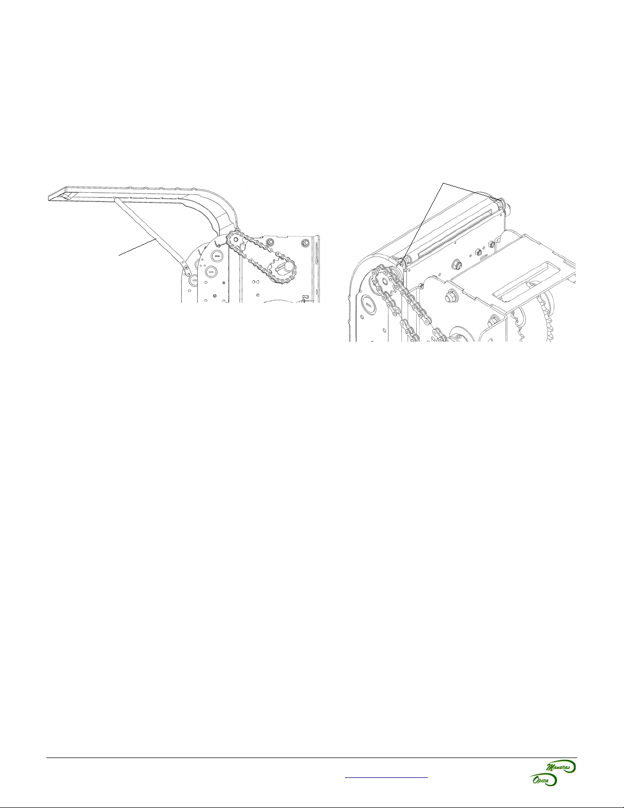
5 Operator Control Box
To open the control box cover, loosen the screw at the base of the cover. If the cover cannot be fully opened, the
retaining arm may be used to hold the cover in other positions, see Figure 9.
After installation, allow for proper clearance upon opening the control box cover. If the cover is obstructed from
opening, it is possible to remove the cover by unscrewing it from the box, see Figure 10.
Always close the cover before operating the door.
Screws
Retaining Arm
Figure 9 - Open Control Box Cover
Figure 10 - Unscrewing Screws from
Control Box Cover
For technical support, please call 1-800-361-2260 or visit www.manaras.com for more information
10
6 Manual Hand Chain and Disconnect Chain
6.1 Installation
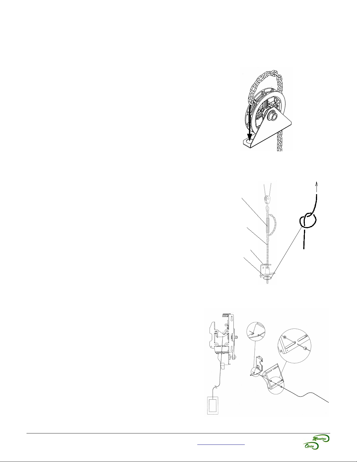
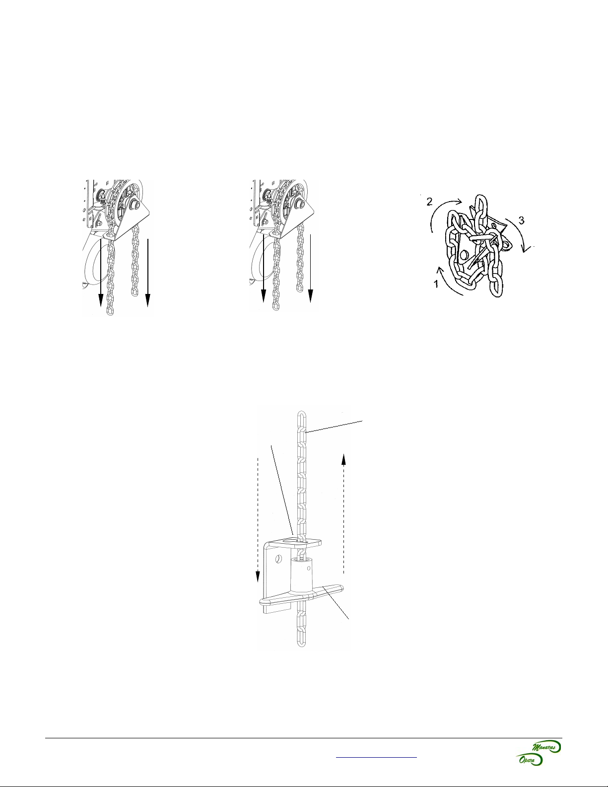
6.1.1 Chain Hoist (Opera-H / SH / HJ)
Before pulling the hand chain through the pocket wheel, pull the limit
cam's retaining bracket back. Turn the cams to the center of the limit
shaft to be sure that they are not being mechanically driven through
their normal limit switch end positions.
1. Run the hand chain through the pocket wheel and through
the chain guide, see Figure 11.
2. Allow both ends of the chain to hang down toward the
ground until both ends are approximately 2 feet (0.6 m) from
the floor. Cut the hand chain if necessary.
3. Connect both ends of the hand chain together.
Figure 11 - Hand Chain Installation
6.1.2 Disconnect Chain (Opera-J / SH)
1. Link the disconnect chain to the hook located at the
extremity of the operator's disconnect mechanism, see
Figure 12.
2. Install the handle under the chain keeper to facilitate
handling of the chain.
3. Under the handle, make a knot in order to fasten the end of
the chain.
Disconnect
Mechanism from
Operator
Disconnect Chain
6.1.3 Emergency Egress (Opera-HJ)
This operator is built to receive a quick disconnect in case of an
emergency egress.
1. Pass the cable housing (from the emergency egress
control) through the holes provided on the frame of the
operator, see Figure 13.
2. Attach the end of the egress cable to the disconnect lever.
3. Secure positioning of the cable housing with two adjustment
collars.
Chain Keeper
Handle
Figure 12 - Disconnect Chain
Knot
Figure 13 - Emergency Egress
For technical support, please call 1-800-361-2260 or visit www.manaras.com for more information
11
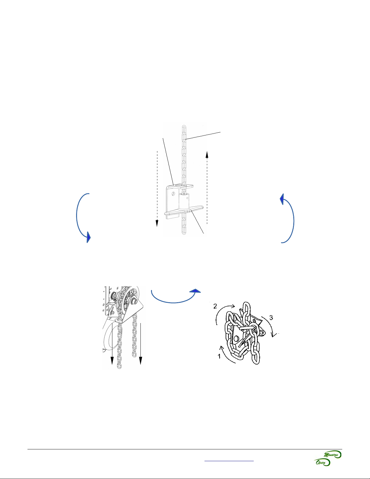
6.2 Operating Mode
6.2.1 Opera-H (Hoist-a-matic® Chain Hoist System)
The automatic emergency chain hoist disconnect mechanism is provided in order to operate the door manually. A floor
level disconnect is not required. In one simple step and by pulling the hand chain in the desired direction, the following
operations may be successfully completed, see Figure 14.
1. Manual Mode 2. Return to Electric Mode 3. Storage
Pull chain on either side
to operate door.
PULL
PULL
Wiggle chain until it
moves freely.
WIGGLE
WIGGLE
Figure 14 - Hoist-a-matic®
Follow the 3 steps shown below to
attach the chain (when not in use)
to the chain keeper.
STORE
STORE
6.2.2 Opera-J
This operator has a floor level disconnect to disconnect the door from the electrical motor and is ready to be manually
operated, see Figure 15.
Disconnect Chain
Chain Keeper
Pull the handle and
attach the
disconnect chain to
the chain keeper for
manual operation.
Release the tension from
the disconnect chain to
return to electrical mode.
Handle
Figure 15 - Floor
Level Disconnect
Chain
For technical support, please call 1-800-361-2260 or visit www.manaras.com for more information
12
6.2.3 Opera-HJ
See section 6.2.1 for Chain Hoist Operation or see section 6.1.3 for Direct “on-the-door” Manual Operation.
Activation of the quick disconnect keeps the operator disconnected mechanically and electrically for manual
operation.
6.2.4 Opera-SH
This operator has a floor level hoist engagement lever to:
– disconnect the electrical control of the operator
– release the brake
– engage the manual hoist mechanism, see Figure 16
Chain Keeper
1. Engagement 4. Return to Electrical Mode
Pull the handle and
attach the disconnect
chain to the chain
keeper for manual
operation.
Handle
2. Manual Mode 3. Storage
Pull chain on either side
to operate door.
Follow the 3 steps shown below to
attach the chain (when not in use)
to the chain keeper.
Disconnect Chain
Release the tension from
the disconnect chain to
return to electrical mode.
PULL
PULL
STORE
STORE
Figure 16 - Hoist Engagement and Hoist Operation
For technical support, please call 1-800-361-2260 or visit www.manaras.com for more information
13
7 Limit Switches & Limit Cams: Adjustment & Functionality
WARNING
To reduce risk of SEVERE INJURY or DEATH to persons:
• Do not attempt to make limit switch adjustments unless power has been electrically disconnected.
7.1 Limit Switch Functionality
Open Limit Switch and Advanced Open Limit Switch
When activated, the Open Limit Switch will stop the operator while the door is travelling in the upward direction.
Should be adjusted accordingly to stop door in fully opened position. The Advanced Open Limit Switch is used for a
radio-control feature and to activate the Timer to Close feature (if used).
Close Limit Switch and Advanced Close Limit Switch
When activated, the Close Limit Switch will stop the operator while the door is travelling in the downward direction.
Should be adjusted accordingly to stop door in fully closed position. The Advanced Close Limit Switch is used for the
operation of a reversing edge or external entrapment protection devices. With this limit switch, the floor is not
considered as an obstacle, therefore the door does not reverse its movement once it reaches the floor.
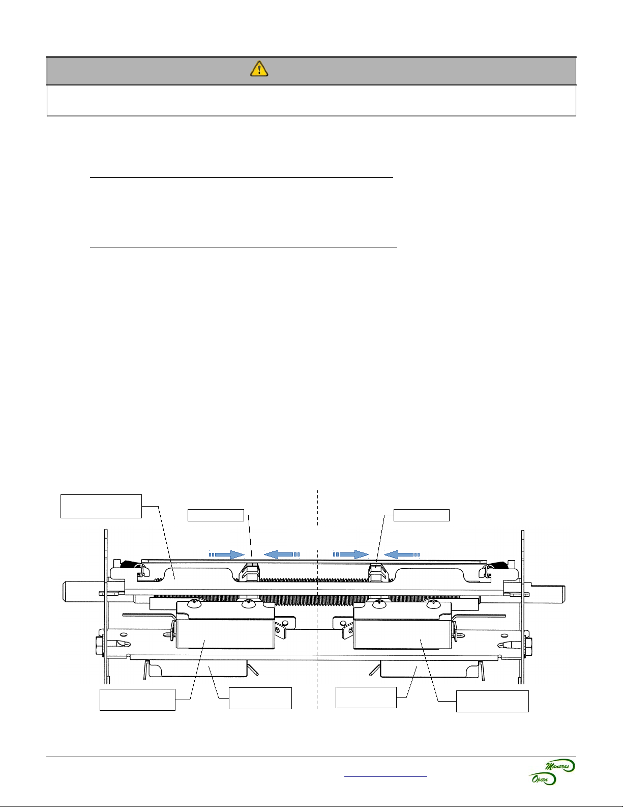
7.2 Limit Switch Adjustments: Open and Close Cam Settings
This operator is equipped with the ACCU-CAM® feature, for precise and quick one-handed limit setting adjustments.
To adjust the limit cams, see Figure 17.
1. Pull the cam's retaining bracket back.
2. Turn the cams for limit adjustment: turning cams toward the center of the limit shaft increases door travel or
turning the cams toward the limit switch decreases door travel.
7.3 Advanced Limit Switch Adjustments
The Advanced Close Limit Switch must be field adjusted in order to deactivate the reversing edge or external
entrapment protection device at a maximum of 6 in (15,2 cm) from the floor. The adjustment can be performed by
changing the position of the Advance Close Limit Switch on its slotted support bracket.
Cam Retaining
Bracket
Open Side
Open Cam Close Cam
Increase
Door Travel
Decrease
Door Travel
Close Side
Increase
Door Travel
Advanced Open
Limit Switch
Figure 17 - Limit Switches and Cams Adjustment
For technical support, please call 1-800-361-2260 or visit www.manaras.com for more information
Open Limit
Switch
Close Limit
Switch
Advanced Close
Limit Switch
14
7.4 Limit Switch Adjustment Using Manual Hand Chain (if applicable)
Table 4 - Limit Switch Adjustment Procedures
Limit Switch Adjustment Procedures
1. Using the hoist, manually raise the door to a nearly opened position or desired open
position.
2. Pull the cam-retaining bracket from the Open side, see Figure 17, and rotate the Open
Open Limit
Advanced
Close Limit
cam manually until it activates the Open Limit Switch sufficiently so that a “click” can be
heard.
3. Release cam-retaining bracket and make sure that the bracket engages in the slots of
both cams.
1. Using the hoist, manually lower the door to approx. 6” above the ground.
2. Pull the cam-retaining bracket from the Close side, see Figure 17, and rotate Close cam
manually until it activates the Close limit switch sufficiently so that a “click” can be heard.
3. Release cam-retaining bracket and make sure that the bracket engages in the slots of
both cams.
Limit Switch
Fine
Adjustment
1. Limit switch fine adjustment SHOULD be done after the main power supply is connected
to the operator. Refer to section Operator Start-up, Table 6, p.22.
Note: One (1) notch on cam is equal (=) to about ½” of the door travel.
7.5 Limit Switch Adjustment Without Manual Hand Chain (if applicable)
Table 5 - Limit Switch Adjustment Procedures (no hoist)
Limit Switch Adjustment Procedures
1. Move the open cam close to the open limit switch and proceed as per described in section
Open Limit
Advanced
Close Limit
Operator Start-up, Table 6, p.22.
2. Release cam-retaining bracket and make sure that the bracket engages in the slots of
both cams.
1. Pull the disconnect chain for manual operation.
2. Manually open the door approx. 6” above the ground.
3. Pull the cam-retaining bracket from the Close side, see Figure 17, and rotate Close cam
manually until it activates the Close limit switch sufficiently so that a “click” can be heard.
4. Release cam-retaining bracket and make sure that the bracket engages in the slots of
both cams.
Limit Switch
Fine
Adjustment
For technical support, please call 1-800-361-2260 or visit www.manaras.com for more information
1. Limit switch fine adjustment SHOULD be done after the main power supply is connected
to the operator. Refer to section Operator Start-up, Table 6, p.22.
Note: One (1) notch on cam is equal (=) to about ½” of the door travel.
15
8 Electrical Wiring
WARNING
To reduce risk of SEVERE INJURY or DEATH to persons:
• All electrical wiring should be done by a qualified professional and in accordance to local
electrical codes.
• Always shut OFF the main power before performing any electrical intervention.
• Use proper wire gauge for incoming power line and for accessory connections.
• Install operator main circuit breaker next to operator for easy access for power shut-off.
• Use separate knockouts on operator control box for accessories and main power cables.
• Always separate low and high voltage wires.
• Operator should be properly grounded to the building ground and to the main power
supply ground lug.
• Always use suitable and appropriate rating circuit breakers for operator protection.
• Compare available power supply voltage to voltage on operator name plate prior to
electrical connection. Failure to connect appropriate power supply voltage may cause
serious damage to the operator.
NOTICE
• THE OPERATOR MUST BE ADEQUATELY PROTECTED AGAINST OVERCURRENT AND SHORTCIRCUIT.
• PLEASE REFER TO LOCAL ELECTRICAL CODE.
• PLEASE REFER TO NATIONAL ELECTRIC CODE (NFPA 70) ARTICLE 430 SECTION IV (430,51 /
430,52 / 430,53).
• PLEASE REFER TO CANADIAN ELECTRIC CODE (CSA 22,1) SECTIONS 28-200 / 28-206.
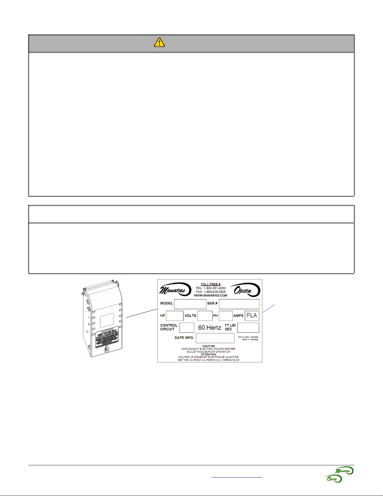
FLA = Full Load Amp
Guideline to determine the branch-circuit rating of the protective device [A]:
Time Delay Fuse: 1,75 x FLA
Non-Time Delay Fuse: 3,0 x FLA
A fuse that does not exceed the next higher standard ampere rating shall be permitted.
Example: If FLA = 3,8A
• Time Delay Fuse: 1,75 x 3,8A = 6,65A → Standard fuse to use: 10A
• Non-Time Delay Fuse: 3,0 x 3,8A = 11,4A → Standard fuse to use: 15A
For technical support, please call 1-800-361-2260 or visit www.manaras.com for more information
 Loading...