

Manaras Opera-MH, Opera-MJ Installation Manual
r
r
r
r
IInnssttaallllaattiioon
O
p
O
p
Read this manual carefully before
Note:
installing the operator and place this installation
manual in an accessible place near the
operator. For future reference record:
Model #
Date
Wiring Diagram #
Serial #
Project No.
Project Name
Door No. #
e
e
n
& IInnssttrruuccttiioonn
&
a--
a
M
M
H
H
O
O
Maannuuaall
M
p
p
e
e
a--
a
M
M
TM
J
J
®
2
IMPORTANT SAFETY INSTRUCTIONS
WARNING
TO REDUCE THE RISK OF SEVERE INJURY OR DEATH, READ AND FOLLOW ALL INSTRUCTIONS
1. Never allow children to operate or play with or near door.
2. Check to see that the operator is correct for the type, size of door and frequency of use per the
operator specifications.
3. If the door system is near a residential area, or pedestrian traffic is expected near the door system,
additional equipment such as electric reversing edges, photocells, or similar devices must be installed
as part of the system to prevent entrapment.
4. Reversing devices appropriate to the application must be installed as part of the system.
5. Outdoor or easily accessible controls must be of the security type to prevent unauthorized use of the
system.
6. Place controls far enough from the door so that a user cannot touch the door when operating the
controls.
7. Controls should be placed so the user has full view of the door when operating.
8. Always keep moving door in sight and away from people or vehicles until it is completely opened or
closed. NO ONE SHOULD CROSS THE PATH OF THE MOVING DOOR.
9. If a person is trapped under the door, push the "OPEN" control button.
10. Do not overtighten a clutch to compensate for a damaged door.
11. Test door and service monthly. After adjusting the limit travel, retest the door opener. Failure to adjust
the door may cause death or injury.
12. KEEP DOORS PROPERLY BALANCED. See door owner's manual. An improperly balanced door
could cause severe injury. Have a qualified service person make repairs to cables, spring assemblies
and other hardware.
13. If possible, use the emergency release only when the door is closed. Use caution when using this
release with the door open. Weak or broken springs may cause the door to fall rapidly, causing injury
or death.
14. You are responsible for assuring that the owner of the door system understands its basic operation and
safety. In particular, be sure the owner/end-user understands the location and operation of the manual
disconnect.
15. Point out to the owner/end-user of the door system that children or pets should not be allowed to play
on or near the door or any part of the system, and that the safety instructions supplied with this
operator are the responsibility of the owner/end-user.
16. Leave the installation and maintenance manual for this operator as well as any additional information
supplied with this operator or other components of the door system with the owner/end-user.
17. If you have any question about the safety of the door operating system, do not install the operator,
contact us.
WARNING
DO NOT CONNECT POWER SUPPLY WHILE INSTALLING, SERVICING OR ADJUSTING THE ELECTRIC
NOT APPLICABLE FOR RESIDENTIAL USE. ONLY FOR INDUSTRIAL AND COMMERCIAL APPLICATIONS
OPERATOR
WARNING

3
TABLE OF CONTENTS
Page
GENERAL PARTS & SPECIFICATIONS ..................................................................................................4
WEIGHT AND DIMENSIONS .................................................................................................................... 4
PRODUCT APPLICATION.........................................................................................................................5
DELIVERY OF OPERATOR ...................................................................................................................... 5
HARDWARE .............................................................................................................................................. 5
INSTALLATION.....................................................................................................................................6-10
LIMIT SWITCHES ...............................................................................................................................10-11
SUGGESTED WIRE SIZE .......................................................................................................................11
WIRING OF AN Opera........................................................................................................................12-13
B2/C2 WIRING.........................................................................................................................................14
OPTIONAL CONTROL ACCESSORIES ................................................................................................. 15
CONNECTION OF SAFETY EDGE.........................................................................................................16
CLUTCH ADJUSTMENT .........................................................................................................................16
OPERATOR START-UP AND TESTING GUIDE ....................................................................................18
TROUBLESHOOTING GUIDE ...........................................................................................................18-20
SCHEDULED MAINTENANCE................................................................................................................21
Opera-MH exploded view.........................................................................................................................22
Opera-MJ exploded view .........................................................................................................................23
Opera-MH/MJ STANDARD ELECTRICAL DIAGRAM ............................................................................24
Opera-MH/MJ STANDARD ELECTRICAL DIAGRAM………………………………………………………..25
WARRANTY……………………………………………………………………………………………………….26
NOTES ....................................................................................................................................................27
4
SPECIFICATIONS
GENERAL
SUPPLY VOLTAGE………………….. 115 VAC single phase
CONTROL VOLTAGE………………. 24VAC class 2 transformer, 2 amp fuse type ACG
MOTOR………………………………. Intermittent duty ½ Horsepower
OPERATOR OUTPUT SPEED……… 39 RPM
NET WEIGHT (Operator only)……… 71 Lbs (33 Kg) for Opera-MH and 61lbs (28 Kg) for Opera-MJ
STANDARD WIRING TYPE………… C2-momentary contact to open and stop and constant pressure to close
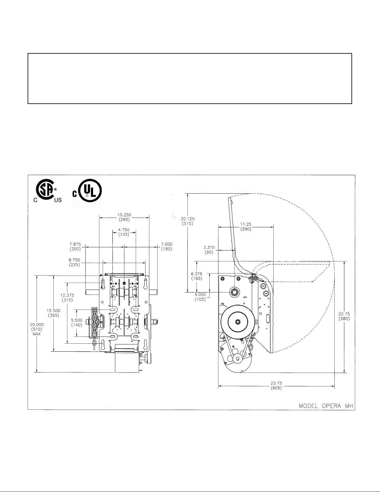
DIMENSIONS
(Opera-MH)
OPERA: MEDIUM DUTY JACKSHAFT OPERATOR
5
IMPORTANT: UPON COMPLETION OF OPERATOR INSTALLATION THIS MANUAL MUST BE GIVEN
TO THE END-USER.
1. PRODUCT APPLICATION
The model OPERA medium duty jackshaft operator is designed for use on commercial or industrial doors
of all types provided that the door has a shaft as basic driving element (sectional doors with high lift, vertical
lift, small rolling doors and grilles). All OPERA door operators are designed and constructed in accordance
with UL325 Standard, and certified by CSA Laboratories.
2. DELIVERY OF OPERATOR
Upon delivery of your medium duty jackshaft operator OPERA, inspect the unit immediately for shipping
damage. Verify that you have received all the hardware parts mentioned in TABLE 1 and shown in Figure 1.
Other items may be present, such as radio controls or other types of optional equipment, if ordered. If any
item is missing or if there is evidence of damage, call the transport company first.
* Check to make sure that the available power supply to be connected to the operator is of the same voltage,
frequency, phase and amperage as indicated on the nameplate of the operator.
3. HARDWARE
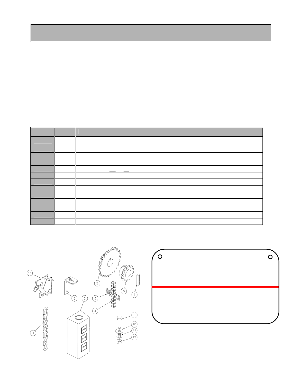
TABLE 1 STANDARD PARTS LIST FOR OPERA JACKSHAFT OPERATOR
PART # QTY DESCRIPTION
1 1
2 1 3-button open/close/stop push-button station
3 1 #41 connecting link
4 1 #41 roller chain x 4'(1.2m) or x 5’ when sprocket is 42 teeth or more.
5 1
6 1
7 1 Square shaft key 1/4" x 1-1/2" L for OPERATM output shaft
8 1 Chain keeper for Opera-MJ only
9 4 3/8" x 1-1/4" bolts
10 4 3/8" washers
11 4 3/8" lock washers
12 4 3/8" nuts
13 1 Chain keeper for Opera-MH only
** See SPECIFICATIONS, DOOR SPEED AND AVAILABLE DOOR ADJUSTMENT
Pocket wheel hand chain (2X door shaft less 4 ft. (1.2m)) for Opera-MH or disconnect chain
(14’) for Opera-MJ
** Sprocket 41B
Sprocket 41B12 x 1,0 " c/w set screws for OPERA
x " c/w set screws for door shaft
TM
output shaft
WARNING
TO PREVENT ENTRAPMENT,
DO NOT START DOOR DOWN UNLESS
DOORWAY IS CLEAR
AVERTISSEMENT
POUR ÉVITER TOUT COINCEMENT, NE
PAS ABAISSER LA PORTE TANT
QUE L’EMBRASURE N’EST PAS LIBRE.
Ensure that the Warning tag supplied with
the operator is properly fixed on the door
and it is visible while the door is moving
Figure 1 Hardware and Warning Tag
6
4. INSTALLATION
All medium duty OPERA jackshaft operators are tested and adjusted at the factory. When installing your
unit, please note that the cams are resting in the center of the cam-shaft.
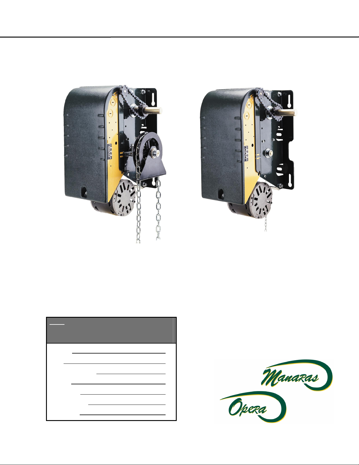
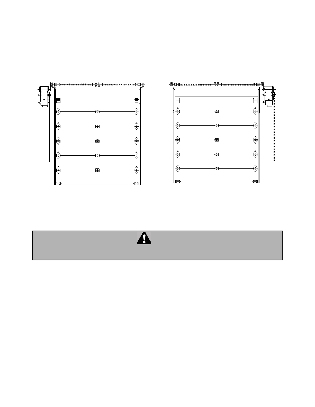
The OPERA operator has a dual output shaft and may be mounted on either the left or right hand side of
a sectional door (see Figure 2 and Figure 3). Place sprocket on either the right or the left end of the
output shaft according to the desired handing.
The Opera-MH comes with a chain hoist located on the right of the operator. If handing requires the
chain hoist to be on the left (rolling doors, left operator hood mounting for ex.), it must be requested at the
time of ordering. Do not attempt to change handing of the chain yourself.
Figure 2 Left side Figure 3 Right side
4.1 IMPORTANT INSTALLATION INSTRUCTIONS
WARNING
TO REDUCE THE RISK OF SEVERE INJURY OR DEATH, READ AND FOLLOW ALL INSTALLATION
INSTRUCTIONS.
1. Installation of this door operator must be done by a qualified installer.
2. Insure that the door is properly installed and works freely in both directions. Do not install the
operator until all door problems have been corrected. If necessary, oil all moving parts (chains,
rollers, guides, etc.).
3. Remove all old accessories (locks, bolts, etc.) before installing door operator.
4. Do not connect the operator to a source of power until instructed to do so.
5. Locate control push-button station within sight of the door, at a minimum height of 5 ft. (1.5 m) so
small children cannot reach it, and away from all moving parts of the door.
7
4.2 INSTALLATION OF OPERA OPERATOR
IMPORTANT NOTE: THIS OPERATOR MUST BE INSTALLED A MINIMUM OF 8 FT. (2.4 m) ABOVE FLOOR.
The OPERA has two sets of mounting holes: outside the frame for wall mounting and inside the frame for
hood mounting.
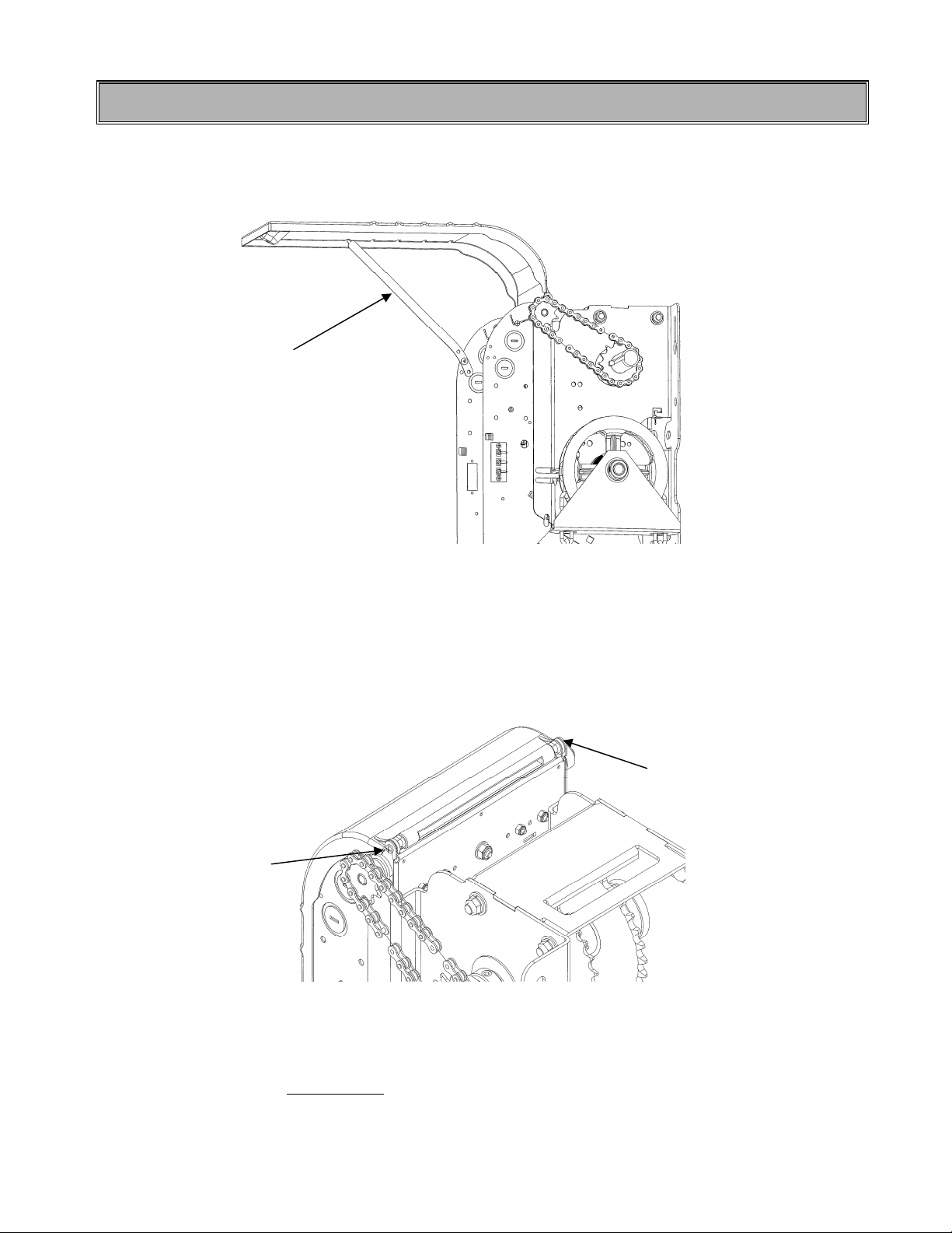
To open the control box cover, loosen the screw at the base of the cover. If the cover cannot be fully
opened, the retaining arm may be used to hold the cover in other positions (Figure 4).
Retaining
arm
Figure 4 Control box cover opening
After installation, verify that there is no obstacle in the way when opening the control box cover. If so, it is
possible to remove the cover by unscrewing it from the box before putting the operator on the wall or
hood (see Figure 5).
Remove the screw
Remove the screw
Figure 5 Unscrewing the cover from the control box
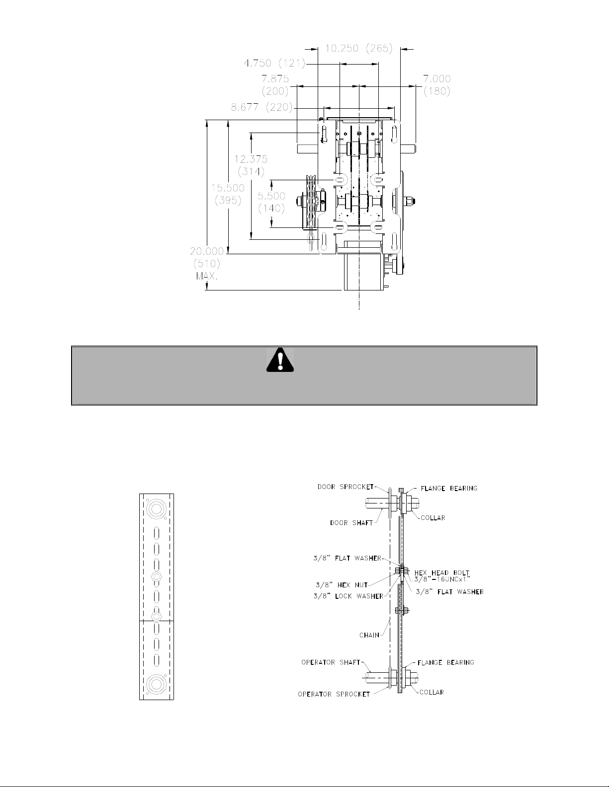
Locate the four mounting holes. The optimum distance between the door shaft and operator drive shaft is
between 12" and 15". Mount the OPERA unit by fastening it to the wall, bench or hood with 3/8" or 1/2"
thru-bolts or if the wall is of such construction so as to prohibit use of thru-bolts, lag bolts and shields of
sufficient size may be used. Do not tighten.
8
Figure 6 Mounting dimensions for wall or hood
CAUTION
MAKE CERTAIN THAT OPERATOR IS PERFECTLY ALIGNED WITH DOOR SHAFT OTHERWISE
DAMAGE CAN OCCUR
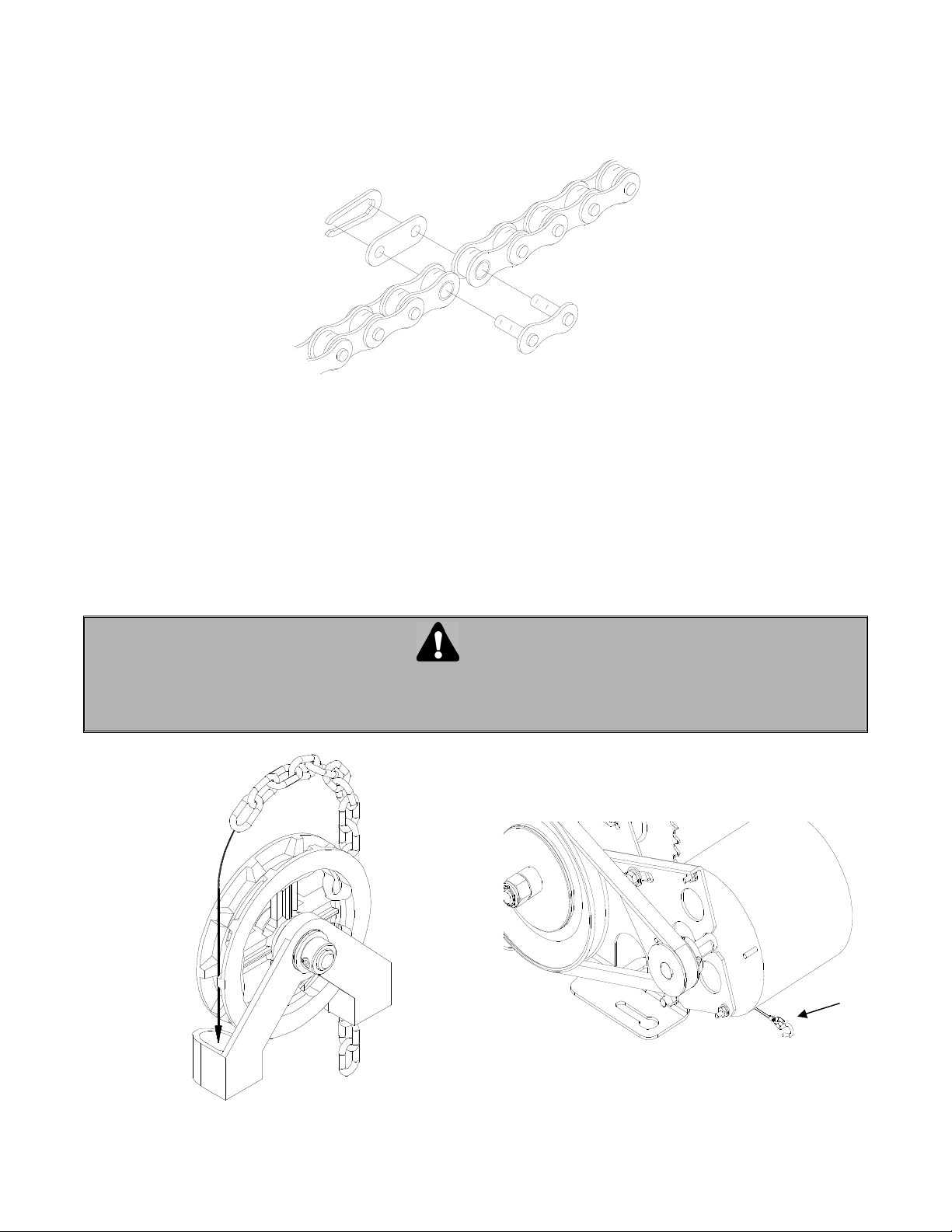
1. Place the driven sprocket on the door shaft loosely and align it with the drive sprocket of the
operator.
NOTE: If a chain spreader has been ordered along with your operator, see Figure 7 and Figure
8 below for installation.
Figure 7 Chain spreader Figure 8 Chain spreader mounted on door and
operator shafts
9
2. Lock the drive and driven sprockets in place by inserting the keys and tightening their respective set
screws.
3. Connect the sprockets with the drive chain, shorten to a suitable length and join together with the chain
link provided in the hardware bag. To shorten the chain, punch out the pin that will leave an inside link
nearest to the desired length. Connect the chain around the sprockets using the chain link (Figure 9).
Figure 9 Chain link
4. Slide the operator to tighten the drive chain and then firmly tighten the mounting bolts. Check the
tension on the chain and the set screws on the sprockets (there should be no more than 1/4" slack
when chain is depressed between sprockets
5. Opera-MH: run hand chain through the pocket wheel and through the chain guide outside the frame
(Figure 10A), allow both ends to hang down toward the ground and cut hand chain, if necessary, so
that both ends are approximately 2 feet (0.6 m) from floor. Connect both ends of hand chain.
6. Opera-MJ: link the disconnect chain at the key ring or hook located at the extremity of the disconnect
pull cable (Figure 10B) Place the Opera-MJ chain keeper so that, when pulled and engaged, the
disconnect chain keeps the machine ‘’disconnected’’ and in the manual position.
CAUTION
BEFORE PULLING HAND CHAIN THROUGH POCKET WHEEL OR LIFTING THE DOOR DIRECTLY BY HAND,
PULL CAM PLATE AND SPIN CAM NUTS TO CENTER OF LIMIT SHAFT SO AS TO BE SURE THE CAMS ARE
NOT BEING MECHANICALLY DRIVEN THROUGH THEIR NORMAL LIMIT SWITCH END POSITIONS.
Keyring
or
Hook
Figure 10 A. Installing hand chain on Opera-MH
Figure 10 B. Installing disconnect chain on Opera-MJ
 Loading...