

Manaras Opera MGT Instructions Manual
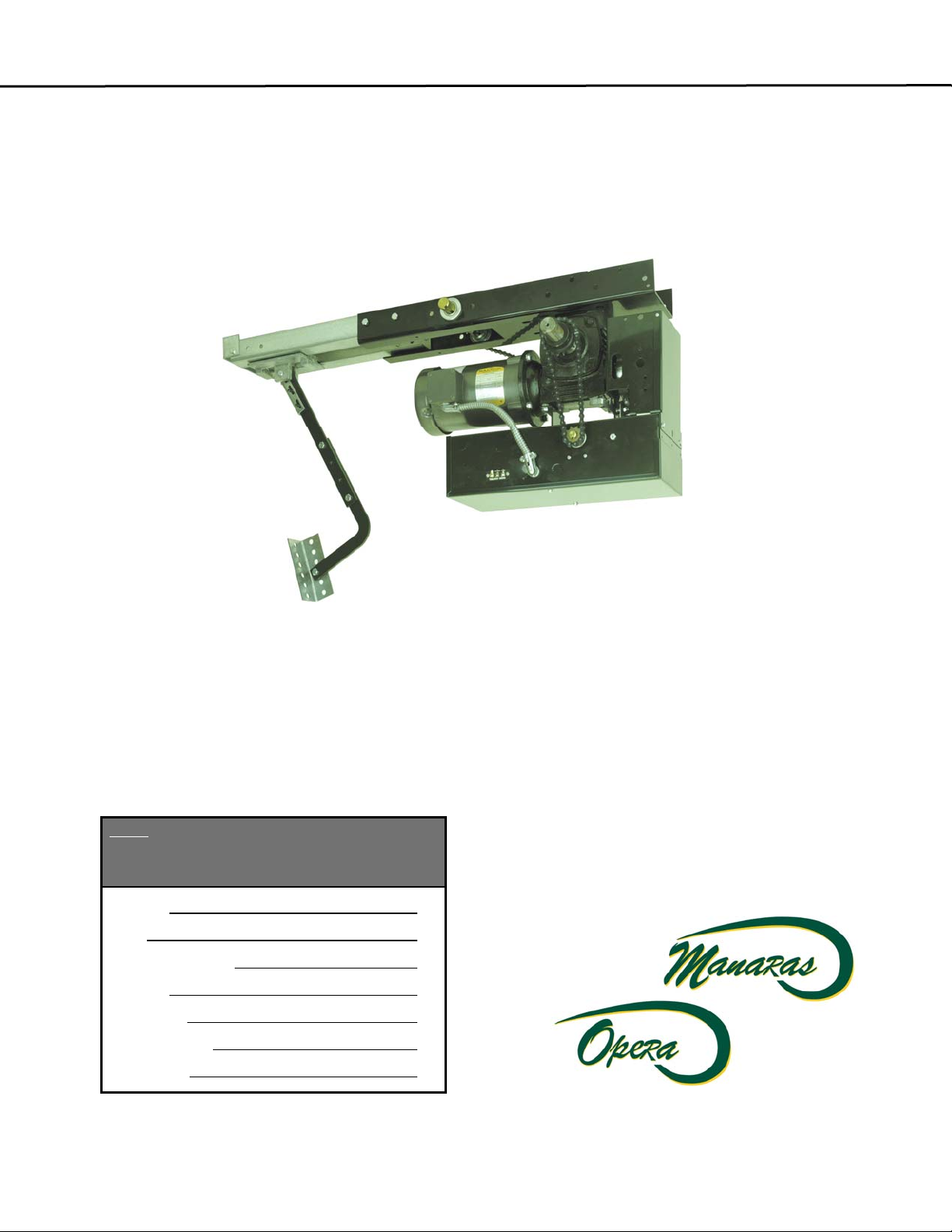
IInnssttaallllaattiioon
& IInnssttrruuccttiioonn
&
Maannuuaall
M
n
Note:
Read this manual carefully before installing
the operator and place this installation manual in
an accessible place near the operator. For future
reference record:
Model #
Date
Wiring Diagram #
Model #
M
M
G
G
T
T
®
Project No
Project Name
Door No. #
TM

2
IMPORTANT SAFETY INSTRUCTIONS
WARNING
TO REDUCE THE RISK OF SEVERE INJURY OR DEATH, READ AND FOLLOW ALL INSTRUCTIONS
1. Never allow children to operate or play with or near door.
2. Check to see that the operator is correct for the type, size of door and frequency of use per the operator
specifications.
3. If the door system is near a residential area, or pedestrian traffic is expected near the door system,
additional equipment such as electric reversing edges, photocells, or similar devices must be installed
as part of the system to prevent entrapment.
4. Reversing devices appropriate to the application must be installed as part of the system.
5. Outdoor or easily accessible controls must be of the security type to prevent unauthorized use of the system.
6. Place controls far enough from the door so that a user cannot touch the door when operating the controls.
7. Controls should be placed so the user has full view of the
door when operating.
8. Always keep moving door in sight and away from people or
vehicles until it is completely opened or closed. NO ONE SHOULD CROSS THE PATH OF THE MOVING
DOOR.
9. If a person is trapped under the door, push the "OPEN" control button.
10. Do not overtighten a clutch to compensate for a damaged door.
11. Test door and service monthly. After adjusting the limit travel, retest the door opener. Failure to adjust the
door may cause death or injury.
12. KEEP DOORS PROPERLY BALANCED. See door owner's manual. An improperly balanced door could
cause severe injury. Have a qualified service person make repairs to cables, spring assemblies and other
hardware.
13. If possible, use the emergency release only when the door is closed. Use caution when using this release
with the door open. Weak or broken springs may cause the door to fall rapidly, causing injury or death.
14. You are responsible for assuring that the owner of the door system understands its basic operation and
safety. In particular, be sure the owner/end-user understands the location and operation of the manual
disconnect.
15. Point out to the owner/end-user of the door system that children or pets should not be allowed to play on or
near the door or any part of the system, and that the safety instructions supplied with this operator are the
responsibility of the owner/end-user.
16. Leave the installation and maintenance manual for this operator as well as any additional information
supplied with this operator or other components of the door system with the owner/end-user.
17. If you have any question about the safety of the door operating system, do not install the operator, contact us.
WARNING
DO NOT CONNECT POWER SUPPLY WHILE INSTALLING, SERVICING OR ADJUSTING THE ELECTRIC
OPERATOR
WARNING
NOT APPLICABLE FOR RESIDENTIAL USE. ONLY FOR INDUSTRIAL AND COMMERCIAL APPLICATIONS

3
TABLE OF CONTENTS
Page
GENERAL PARTS & SPECIFICATIONS
WEIGHT AND DIMENSIONS
PRODUCT APPLICATION
DELIVERY OF OPERATOR
HARDWARE
INSTALLATION
CLUCTH ADJUSTMENT
BRAKE ADJUSTMENT
SCHEDULED MAINTENANCE
MGT EXPLODED VIEW
4
4
5
5
5
6
11
11
13
14
SPECIFIC TO ELECTRONIC CONTROL BOARD 15
• Power, Control and Accessory Wiring 16
• Program Setting
• Mode Setting
20
21
• Door Lock Sensor
• Troubleshooting on ECB
• Single phase Wiring Diagram
• 3-phase Wiring Diagram
22
23-24
25
26
SINGLE BUTTON RADIO CONTROL & RED & GREEN WARNING LIGHTS 27
• Warning lights sequence 28
• Programming of warning lights sequence
• Connection of Red & Green lights
28
28
SPECIFIC TO HARDWIRED ELECTRIC CONTROL 29
• Wiring of a MGT 30-31
• Accessory wirind diagrams
• Troubleshooting on hardwiring circuit
• Single phase Wiring Diagram
32-33
36-37
38
• 3-phase Wiring Diagram 39
WARRANTY POLICY 40
NOTES
41-43
4
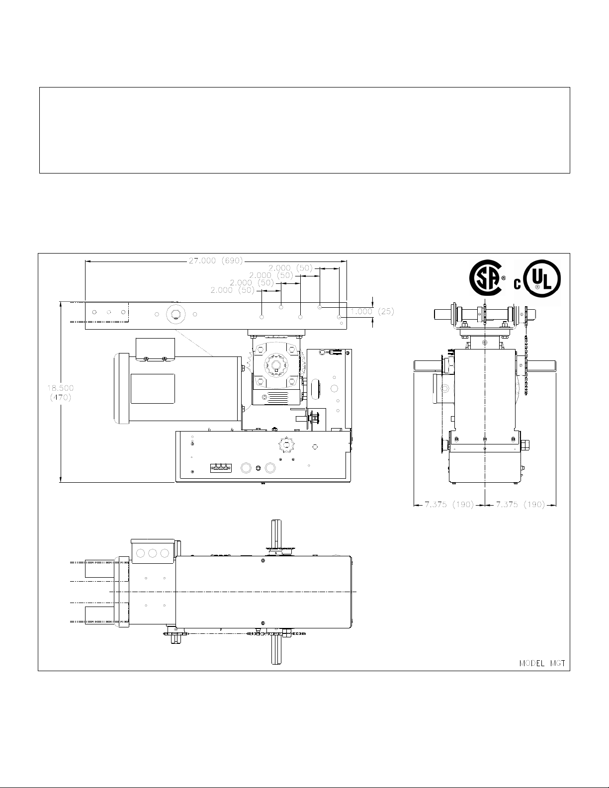
SPECIFICATIONS
GENERAL
SUPPLY VOLTAGE………………….. 115, 230 VAC single phase 208, 460, 575 VAC three phase
CONTROL VOLTAGE………………. 24VAC class 2 transformer, 2 amp fuse type ACG
MOTOR……………………………… Continuous duty 1/2, 3/4, 1 & 1.5 Horsepower
OPERATOR OUTPUT SPEED……… 103.5 RPM
WEIGHT (net)………………………… 126 lbs (approx), 56.8 kg
STANDARD WIRING TYPE…………… C2 momentary contact to open and stop and constant pressure to close.
DIMENSIONS
(MGT)
5
MGT: THE TROLLEY OPERATOR
IMPORTANT: UPON COMPLETION OF OPERATOR INSTALLATION, THIS MANUAL MUST BE
GIVEN TO THE END-USER
1. PRODUCT APPLICATION
The model MGT heavy-duty trolley operator is designed for use on standard lift overhead sectional garage
doors. All M G T door operators are designed and constructed in accordance with UL and CSA standards.
2. DELIVERY OF OPERATOR
Upon delivery of your heavy-duty trolley operator, inspect the unit immediately for transport damage. Verify that you
have received all the hardware requested with your order (Table 1). Other items may be present, such as radio
controls or other types of optional equipment, if ordered. If any item is missing or if there is evidence of damage, call
the transport company first.
* Check to make sure that the available power supply to be connected to the operator is of the same voltage,
frequency, phase and amperage as indicated on the nameplate of the operator
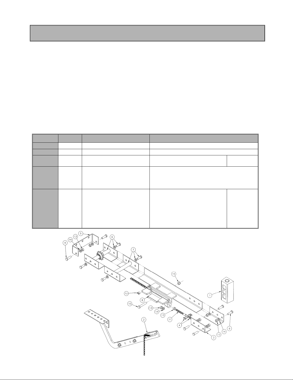
3. HARDWARE
TABLE 1 STANDARD PARTS LIST FOR MGT TROLLEY OPERATOR
# Qty Code
Description
1 1 STATION020 3 push-button station
2 1 DOORARM001 Door lifting arm assembly
3
4
5
6
7
8
9
10
11
12
13
14
15
2
1
1
1
2
1
6
1
1
1
8
7
1
TRACKxxx
CHAINxxx
BRACKET043
FRONTIDLER007/010
SHAFT017
CARRIAGE006
BOLT026
BOLT031
BOLT035
LINK004
NUT010
WASHER030
NUT022
Pre-drilled galvanized track
#41Drive Chain
Front end U-bracket
#41Front idler assembly
Spacer
Carriage
Hex head bolt 3/8-16UNC x 1-1/4
Hex head bolt 3/8-16UNC x 2-1/4
Take-up bolt 3/8 x 2-1/2
Connecting chain link
Hex nut 3/8-16UNC
Lock washer 3/8
Stop nut 3/8
Txxx
T2-HBAG
Figure 1 Hardware
A
4. INSTALLATION
6
All heavy-duty trolley operators are tested and adjusted at the factory. When installing your unit, please note that the
cams are resting in the center of the camshaft.
4.1 IMPORTANT INSTALLATION INSTRUCTIONS
WARNING
TO REDUCE THE RISK OF SEVERE INJURY OR DEATH, READ AND FOLLOW ALL INSTALLATION
1. Installation of this door operator must be done by a qualified installer.
2. Insure that the door is properly installed and works freely in both directions. Do not install the operator until all
door problems have been corrected. If necessary, oil all moving parts (chains, rollers, guides, etc.).
3. Remove all old accessories (locks, bolts, etc.) before installing door operator.
4. Do not connect the operator to a source of power until instructed to do so.
5. Locate control push-button station within sight of the door, at a minimum height of 5 ft. (1.53 m) so small
children cannot reach it, and away from all moving parts of the door.
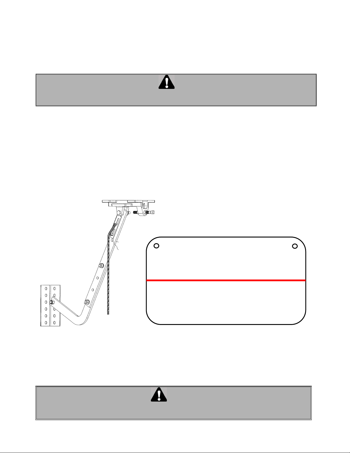
6. Ensure that the warning tag supplied with the operator is properly fixed on the door and it is visible while the
door is moving. (Figure 2)
INSTRUCTIONS
WARNING
TO PREVENT ENTRAPMENT,
DO NOT START DOOR DOWN UNLESS
DOORWAY IS CLEAR
VERTISSEMENT
POUR ÉVITER TOUT COINCEMENT, NE
PAS ABAISSER LA PORTE TANT
QUE L’EMBRASURE N’EST PAS LIBRE.
Figure 2 Warning tag
WARNING
STAND CLEAR OF DOOR AND VERIFY THAT DOORWAY IS CLEAR, THEN PULL EMERGENCY
RELEASE DISCONNECT LEVER TO DISCONNECT OPERATOR FOR MANUAL OPERATION OF DOOR
4.2 INSTALLATION OF MGT OPERATOR
7
IMPORTANT NOTE: THIS OPERATOR MUST BE INSTALLED A MINIMUM OF 8 FT (2.4 m) ABOVE FLOOR
Before the operator is installed, ensure that door has been properly aligned and is working smoothly.
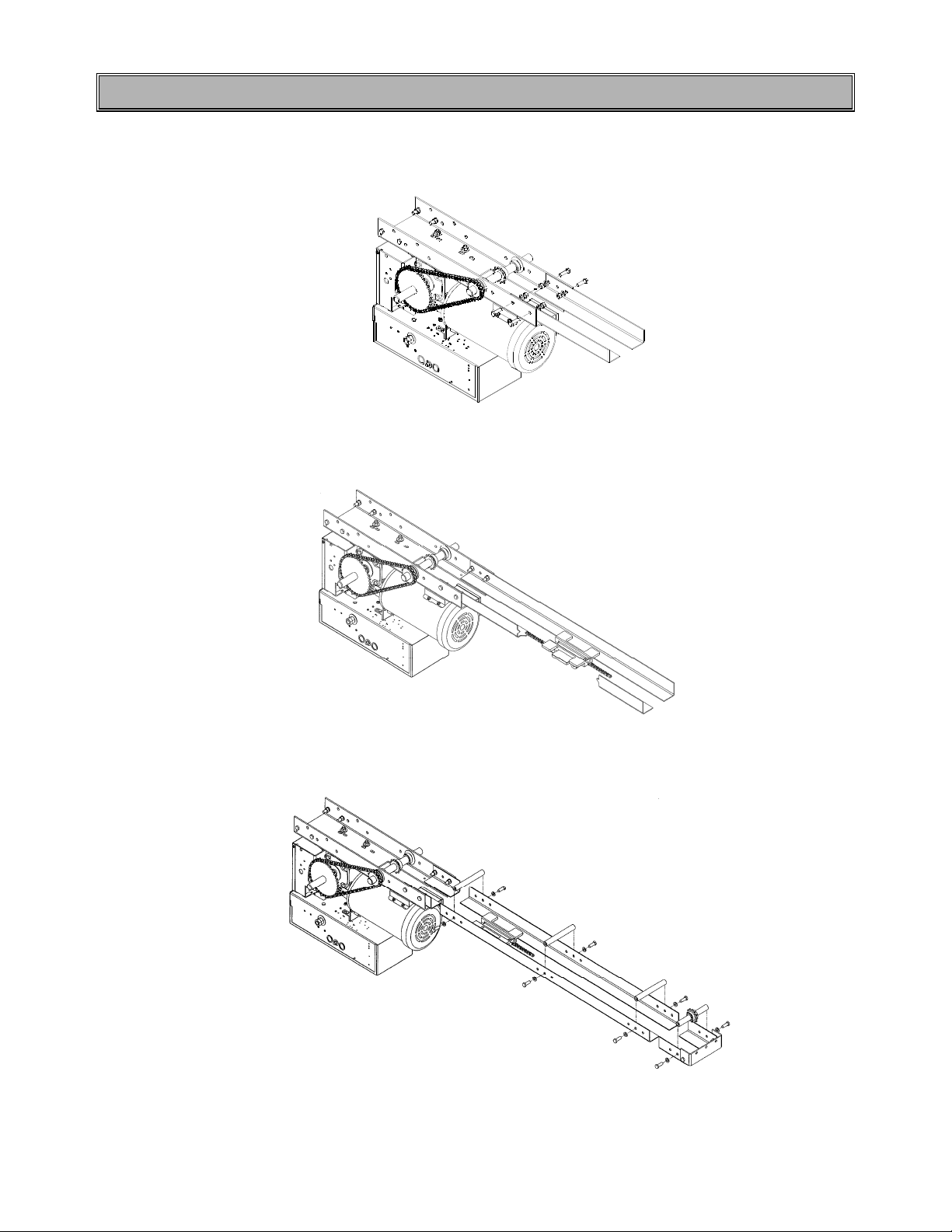
It is advisable to assemble the operator to the trolley tracks on the floor prior to installation.
1. Bolt the tracks to the operator using bolts provided (Figure 3).
Figure 3 Assembling operator and tracks
2. Place carriage on rails and slide to forward position, making sure that the chain take-up bolt is facing the
operator (Figure 4).
Figure 4 Inserting carriage in tracks
3. Attach front idler and rail spreaders as shown in Figure 5.
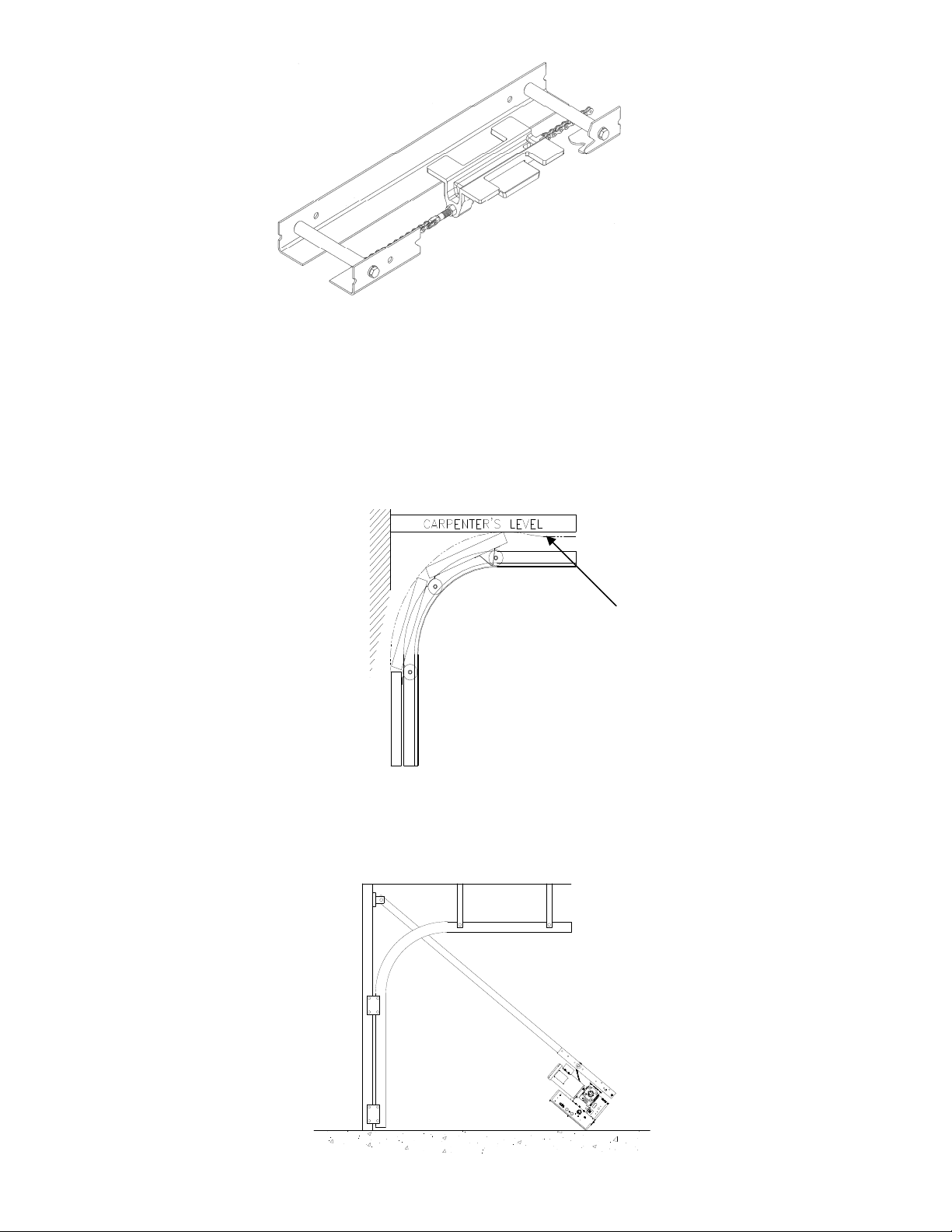
4. Attach one end of the chain to the to the carriage using a chain link (Figure 6). Run chain around front idler and
continue around drive sprocket on operator. Then fix second end of the chain using an another chain link to the
take-up bolt and fix the take-up bolt to thee carriage. Chain could then be tightened by adjusting the take-up bolts
in carriage. Properly adjusted chain should sag approximately 2” (5 cm) at halfway point on tracks
Figure 5 Front idler and spreaders
6
7
8
Figure
Installing chain
Note: All trolley operators are designed to mount directly over the center of the door, and the operator tracks
should clear the door by approximately 2.5" (6.4 cm). If it is not possible to mount the operator exactly
centered, it is possible to install it slightly off center for torsion spring doors.
5. Establish center line of door by measuring door width and marking a vertical line on the wall directly above the
door.
6. Open the door manually to determine the high arc (highest point) of door travel (see Figure 7). Using a
carpenter's level draw a line so that it will intersect with the vertical line determined earlier.
HIGH ARC POINT
Figure
Highest arc of travel
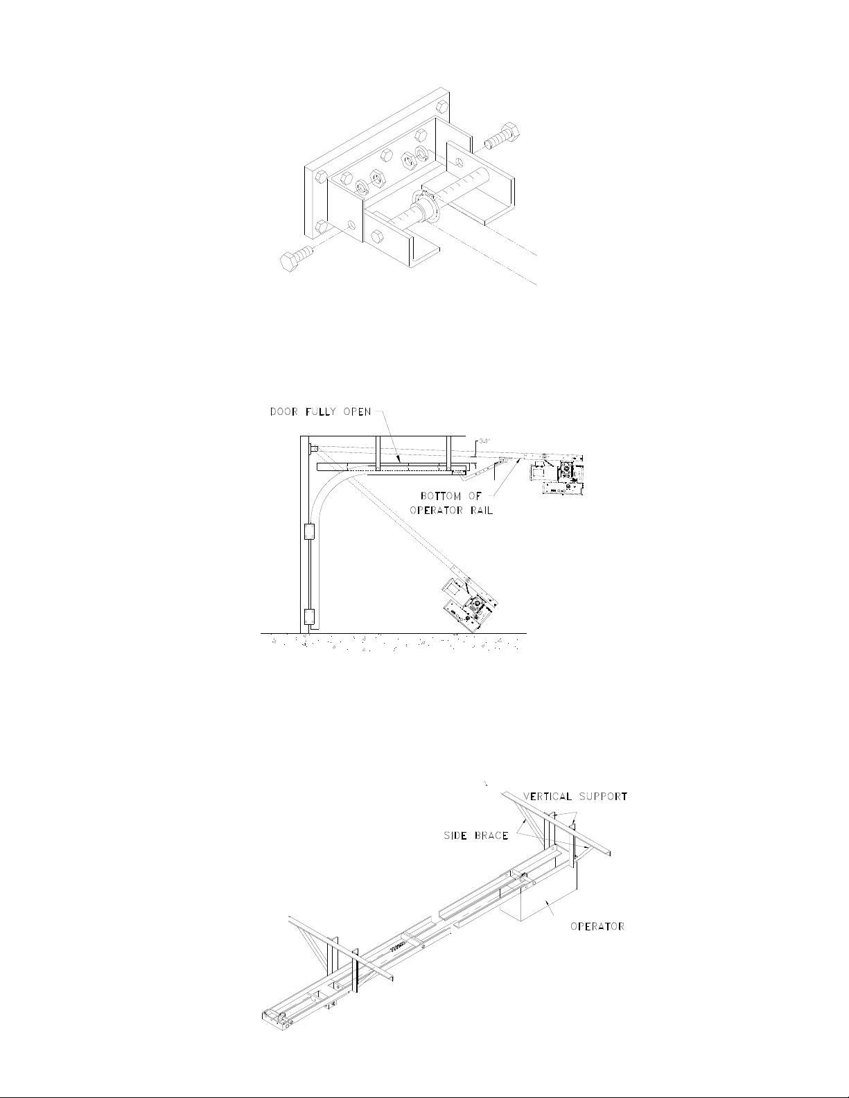
7. The wall mounting bracket has three bolt holes for mounting the front end of the trolley tracks. The bracket
should be attached to the wall with these holes 2.5" (6.4cm) above the high arc of door (Figure 8). Wood blocking
or angle iron framework may be installed on the wall to provide for the attachment of the front bracket.
Figure 8 Wall mount bracket
9
8. After securing the wall mounting bracket, allow the motor to rest on floor and raise the front end of the rails and
secure (but not tighten) with 5/16” bolts and nuts (Figure 9). If torsion hardware is preventing the rails from liningup with the wall bracket, secure temporarily with cord.
Figure 9 Installing tracks on wall bracket
9. Hoist rear of operator using block & fall or other suitable means above level of horizontal door tracks and
temporarily secure in place using rope or chain. Tighten front end bracket bolts.
10. Carefully open door by hand and move rear of operator so that it is directly over center of door, with
approximately 3" clearance between door and bottom of operator rails (Figure 10).
Figure 10 Adjusting height of operator
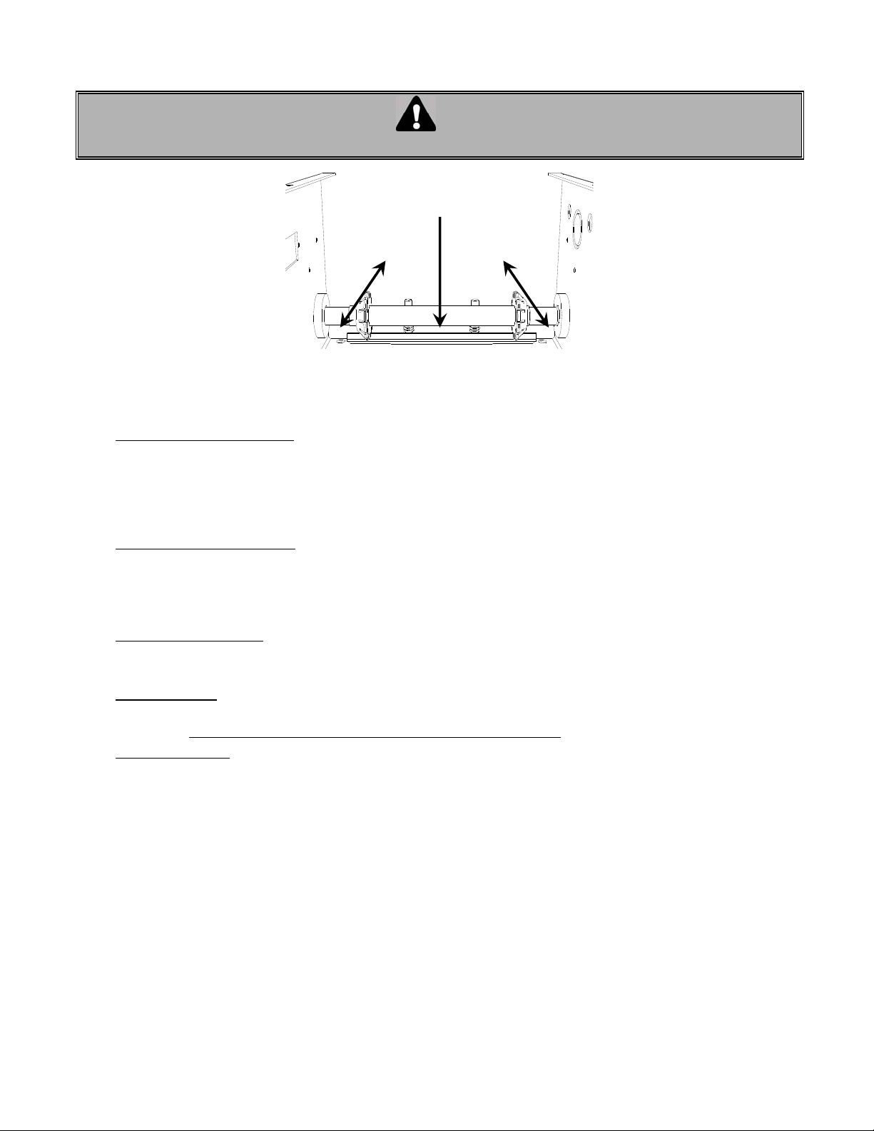
11. Hanging brackets may now be affixed from ceiling to operator (Figure 11). Two or more holes are provided in
frame of operator for this purpose. Take care that unit remains centered over door during installation of hangar
brackets. After vertical drops are made and secured, side braces should be installed.
12. Approximately 5 feet (1.5 m) from forward end of rails, locate set of 3/8" holes for angle iron braces to secure
rails. Two drops pieces should be installed at this point to further strengthen installation (Figure 11).
Figure 11 Location and installation of hangers and side braces
10
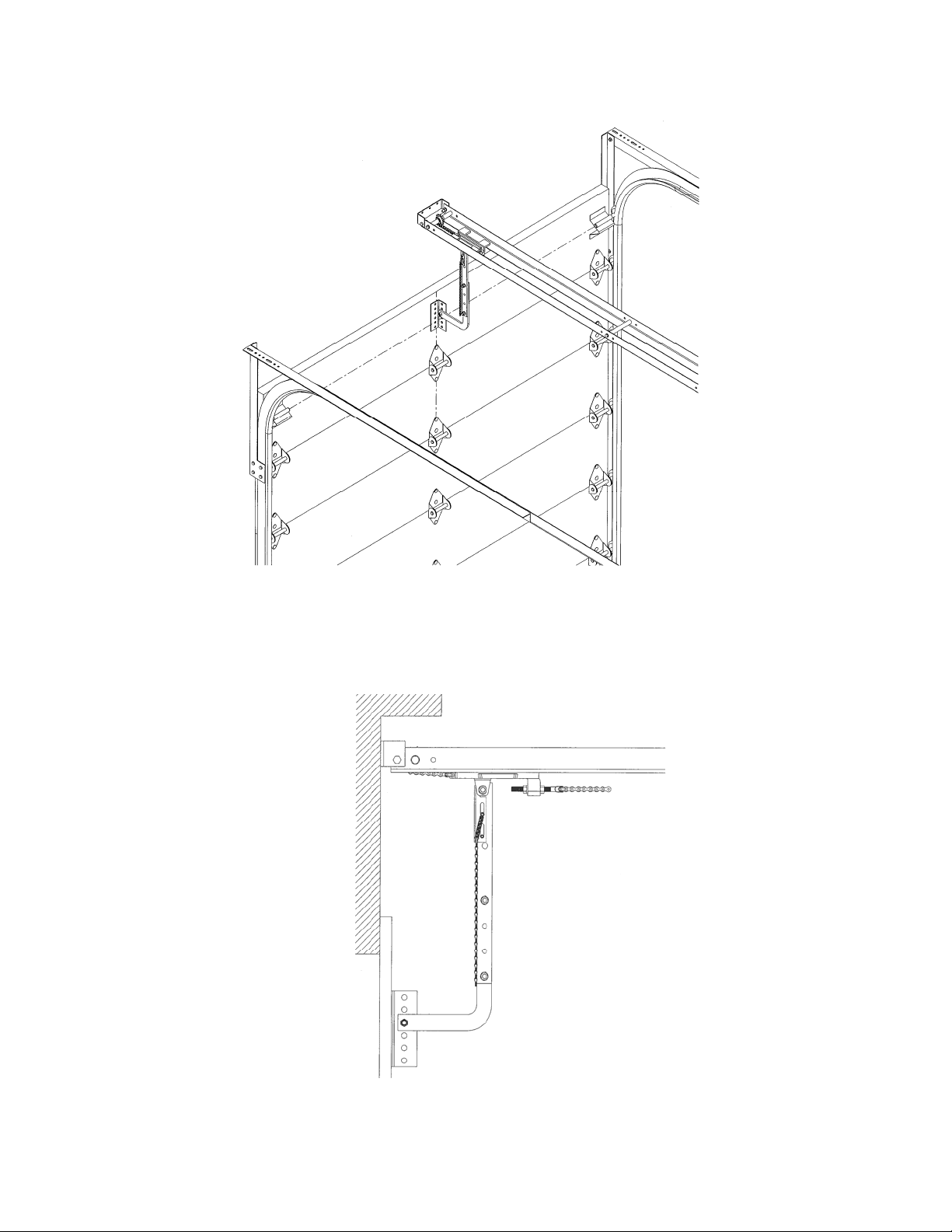
13. Close door. Connect door arm to carriage using 3/8" x 2-1/4" bolt furnished. Fasten door bracket to arm and
position on door as shown in Figure 12. Mount door bracket to center of door in such a way that the door bracket
is also in line with the top rollers on the door.
Figure 12 Installing door arm to door
14. Door arm should always lean vertical (Figure 13).
Figure 13 Position of door arm
4
11
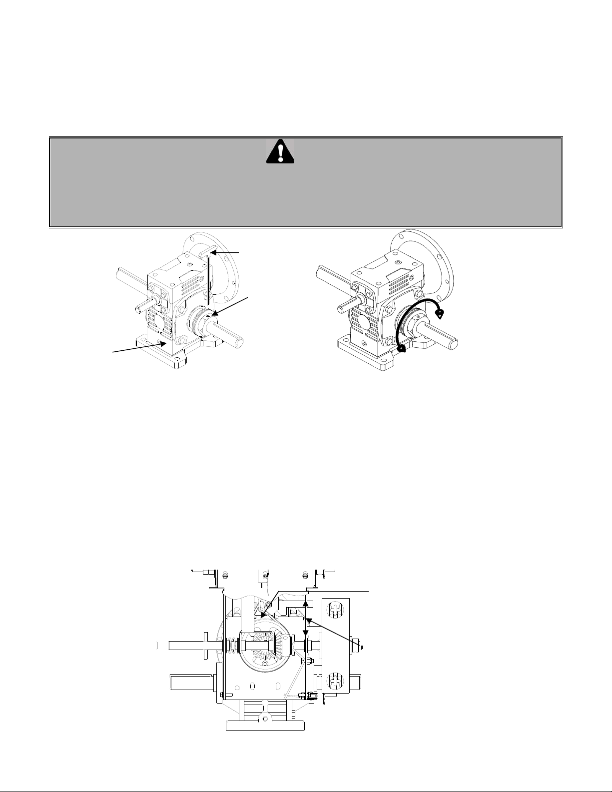
4.3 CLUTCH ADJUSTMENT
1. Loosen clutch set screws (Figure 14 A).
2. Back off clutch nut until there is insufficient tension on clutch spring to permit clutch to drive door (Figure 24 B).
3. Tighten clutch nut gradually until there is just enough tension on spring to permit operator to move door smoothly,
but allow clutch to slip if door is obstructed.
4. When clutch is properly adjusted it should be possible to stop door by hand during travel.
5. Be sure to tighten clutch set screws each time operator is tested for clutch adjustment and that it is locked in place
on completion of adjustments.
WARNING
THE FRICTION CLUTCH IS DESIGNED TO PROTECT VEHICLES AND DOOR HARDWARE AGAINST DAMAGE. IT IS
NOT INTENDED TO PROTECT PEOPLE. ALL DOORS SERVING PERSONNEL ARE TO BE FITTED WITH AN
APPROPRIATE REVERSING DEVICE OR REVERSING EDGE TO PREVENT INJURY OR DEATH.
If an automatic reversing device is desired, several types are available as accessories. Consult your dealer for a
recommendation.
Figure 24 A
Reducer
BRAKE ADJUSTMENT
• The brake is factory set. However, after extensive use the brake may need to be adjusted.
• In order to obtain best performance and maximum life, the brake must be adjusted for:
• Proper clearance between the brake band and the brake drum when the solenoid is energized.
• Correct brake tensioning when the solenoid is de-energized.
TO ADJUST THE BRAKE SYSTEM:
1. Remove the solenoid cover.
2. Slightly unscrew the pivot nut (Figure 15)
3. To adjust the brake band tension, move the adjustment lever. To increase tension, move the lever away from
the motor. To decrease tension, move the lever toward the motor
4. Tighten the pivot nut
5. Check clearance but manually holding the solenoid plunger. The brake drum should rotate easily by hand.
6. After adjustment is done, re-install the solenoid cover.
Allen
Key
Set screw
Clutch nut
Figure 1
&
Reducer adjustment
Figure 24 B
Use an appropriate
key to adjust the
clutch
Pivot nut
Lever
Figure 15 Brake system
6
12
4.4 ADJUSTMENT OF LIMIT SWITCHES
1. Open the cover of the electrical enclosure.
WARNING
NEVER PLACE HANDS OR TOOLS INSIDE OPERATOR OR NEAR DRIVE MECHANISM UNLESS POWER IS OFF
Press down on
cam retaining plate to
rotate cams
Rotate cams to
desired position
Open Cam
(Open side)
Figure 1
Adjusting the limit cams
Close Cam
(Close side)
Note: Turning the cam towards the center on the limit shaft increases door travel.
Turning the cam towards the limit switch decreases door travel.
• Open limit switch adjustment:
2. Manually raise the door to a nearly opened position or desired open position.
3. Depress the cams-retaining bracket from the Open side and rotate manually the Open cam (Figure 16)
until the cam activates the limit switches sufficiently so as to hear the switches click (2 clicks for hardwired
circuit. Only one click with ECB and check if the OPEN limit light is ON).
4. Release cam-retaining bracket and make sure that the bracket engages in the slots of both cams.
• Close limit switch adjustment:
5. Manually lower the door to a nearly to 6” above the ground.
6. Depress the cams-retaining bracket from the Close side and rotate manually the Close cam (Figure 16)
until the cam activates the Close limit switch sufficiently so as to hear the switch click (2 clicks for hardwired
circuit. Only one click with ECB and check if the CLOSE limit light is ON).
• Testing door electrically:
7. Upon completion of all wiring connections, use the wall push buttons (or on board buttons for ECB), to run
the door electrically and check if it is stopping properly to fully open and fully close positions.
• Fine adjustment:
If door is not opening or closing properly or if there is a gap between the door and floor, re-adjust the close
limit switch. Note: One (1) on cam is equal to about ½” on the door travel.
For close position:
Adjust one notch at a time until the close limit switch is properly adjusted and the door
stop smoothly on closed position.
8. Close the control box once the limit switches are adjusted.
4.5 MINIMUM SUGGESTED WIRE SIZE FOR CONTROL CIRCUIT
The control circuit operates at 24 VAC. Due to the resistance in the wire used to carry the control circuit voltage, it
is important to use the appropriate wire size with respect to the distance between the operator and the pushbutton station.
Below is a chart (TABLE 2) indicating the minimum recommended wire size with respect to the total distance
between the operator and the push-button station. DO NOT exceed the maximum distance. If there are
several push-button stations in series you must ADD all these distances before selecting the appropriate wire
gauge for your operator.
If the wire gauge is not suitable for the distance, problems in operation will be encountered such as chattering
relays and contactor, premature wear of the contacts and possible tripping of the motor's thermal protection.
If a greater distance is required, a long distance interface module is suggested (consult factory).
When large gauge wire is used, a separate junction box will be needed for operator power connection (not
supplied).
13
All power wiring to the operator should be installed by a qualified electrician and may vary with respect to conduit
size and type as specified in the National Electrical Code, Article 430, allowing 5% voltage drop. Power must also
be connected in accordance with local codes.
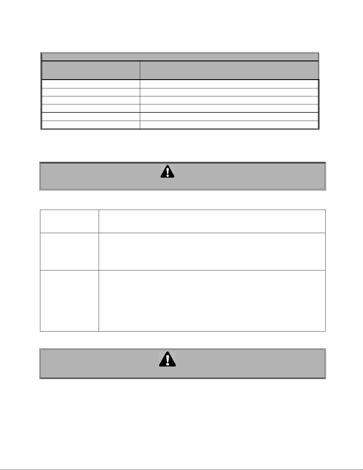
TABLE 2 WIRE SIZE vs. DISTANCE
24 VAC CONTROL WIRING
Minimum suggested
Wire gauge (AWG)
22 50 (15)
20 100 (30)
18 150 (45)
16 250 (75)
14 350 (105)
12 450 (135)
5. SCHEDULED MAINTENANCE
Inspection and service should be performed anytime a malfunction is observed or suspected.
WHEN SERVICING - ALWAYS DISCONNECT OPERATOR FROM POWER SUPPLY
Maximum distance between operator and all
Push-button stations feet (meters)
WARNING
5.1. MECHANICAL
• The door area should always be kept clear of dirt, rocks or any other substance to insure proper operation.
- Check and adjust the brake band and the solenoid, if needed.
EVERY 3 MONTHS
- Check and adjust the clutch, if necessary.
- Check all safety features, if responding properly (photocells, pneumatic etc)
- Check the oil level in the gearbox.
- Lubricate all moving parts, bushings are oil impregnated and are lubricated for life.
EVERY 6 MONTHS
- Verify that all mechanical parts function properly.
- Inspect the V-belt and adjust or replace if necessary.
- Manually operate the door. If the door does not open or close freely, correct the
cause of the malfunction.
- Inspect all bolts and screws and tighten if necessary.
- Check for any excessive slack in chains and adjust or replace them if necessary. The
limit switches may have to be reset after a chain adjustment.
- Inspect the door for wear and damage.
ONCE A YEAR
- Run the operator a few cycles:
Make sure that the door rollers are rolling smoothly on the track.
Listen to the motor: The motor should hum quietly and smoothly.
Verify that the limit operates quietly and smoothly: investigate any unusual noise.
- Verify that the mooring bolts are holding the unit securely.
- Inspect the unit for evidence of corrosion.
5.2. ELECTRICAL
WARNING
BEFORE OPENING THE CONTROL BOX COVER, DISCONNECT OPERATOR FROM POWER SUPPLY
• Inspect the wiring compartment and remove any dirt from the control units.
• Verify all the grounding wires and terminations for corrosion. Be particularly careful to check the ground wires.
• Check the terminal strip to insure that all the screws are tight.
• Verify that the security systems installed on the operator are fully operational.
• Verify the voltage at the input terminals while the operator is running. The voltage must not drop more than 10%
momentarily. If the voltage drop is too deep when running, the relays may chatter, the contact points will wear
prematurely and may eventually weld. Verify the power terminations for corrosion.
• Verify the current consumption of the unit with an amp-meter. The value of current should be consistent with the
nameplate specifications. Investigate any anomaly.
14
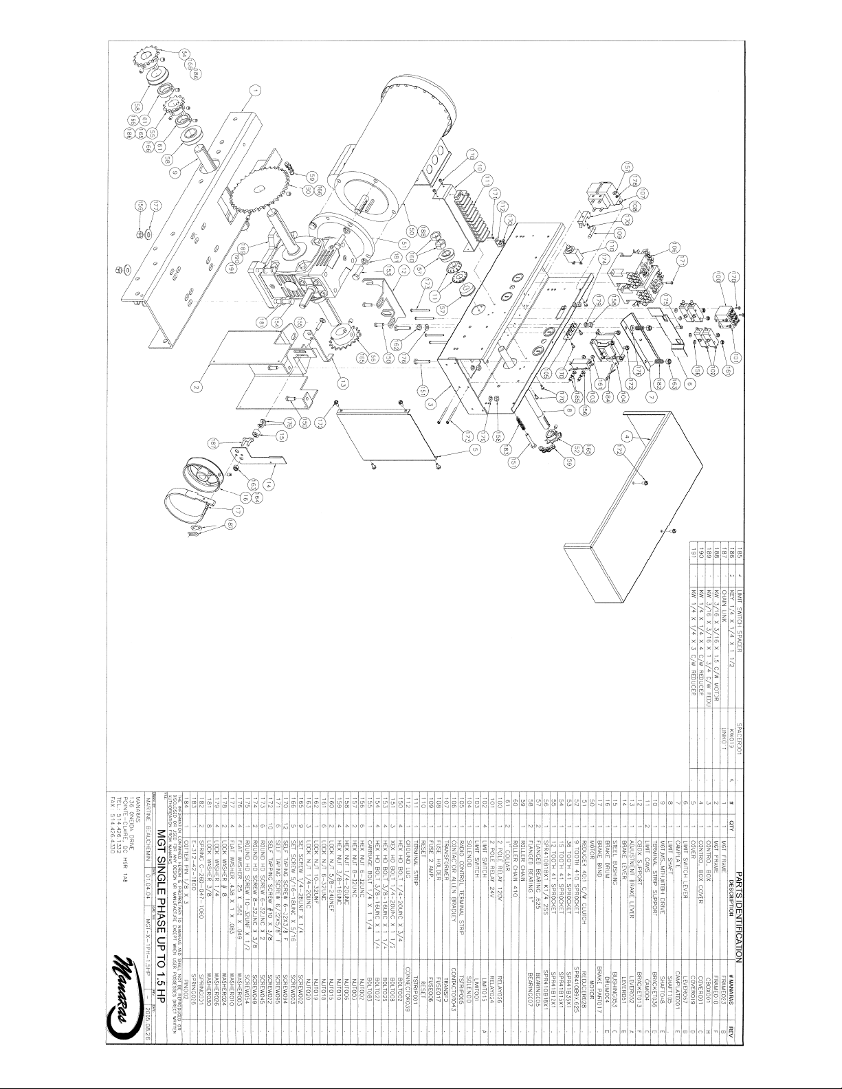
6. MGT exploded view
 Loading...