

Page 1

THIS INSTRUCTION BOOKLET CONTAINS IMPORTANT SAFETY INFORMATION.
PLEASE READ AND KEEP FOR FUTURE REFERENCE.
Date 2018-05-29 Rev. 0001-A Factory: JIYIFO
Assembly Manual
Tenley Twin Over Full Bunk Bed
Stock # TENTOFBB-BR
# TENTOFBB-GR
# TENTOFBB-BR-E
# TENTOFBB-GR-E
Page 2

2 Need Assistance? Call us at 1-888-301-0332 from 8am to 5pm CST Monday - Friday
We are so confident you will be delighted with your Member’s Mark
purchase that we promise to refund or replace any item you find
unsatisfactory. We aim to delight all our members and would love to
hear about your discoveries! Call us at: 1-888-301-0332 (toll-free),
8am - 5pm CST Monday - Friday.
Important Safety Information
Please read all instructions carefully before assembling this furniture.
For your safety, assembly by two or more adults is strongly recommended.
Use only vendor-supplied hardware to assemble this item. Using unauthorized hardware
could jeopardize the structural integrity of the item.
Hardware may loosen overtime. Periodically check that all connections are tight.
Before Assembly
Remove all parts and hardware from the box. Place all items on a carpeted or scratch-free
work surface, as this will avoid damaging parts during assembly.
The shipping box provides an ideal work surface.
To avoid accidentally discarding small parts or hardware, do not dispose of any packaging
or contents of the shipping carton until assembly is complete.
Use the parts and hardware lists below to identify and separate each of the pieces included.
The use of power tools for assembly is not recommended. Power tools can damage the
hardware and/or split the wood.
NOTE: Do not fully tighten all bolts until all parts are in place. Failure to follow these
instructions may cause the bolts to misalign during assembly.
Care and Cleaning
Use a soft, clean cloth that will not scratch the surface when dusting.
Use of furniture polish is not necessary. Should you choose to use polish, test first in an
inconspicuous area.
Using solvents of any kind on your furniture may damage the finish.
Never use water to clean your furniture as it may cause damage to the finish.
Liquid spills should be removed immediately. Using a soft clean cloth, blot the spill gently.
Avoid rubbing.
In the event that your furniture is stained or otherwise damaged during use, we recommend
that you call a professional to repair your furniture.
Page 3
Need Assistance? Call us at 1-888-301-0332 from 8am to 5pm CST Monday - Friday 3
Mattress thickness is from 7 in. (17.78 cm) to 9 in. (22.86 cm) use on lower bunk bed, and
maximum mattress thickness must not exceed 9 in. (22.86 cm) use on upper bunk bed.
Use only mattress which is 74 in. (1.88 m) to 75 in. (1.90 m) long and 37 ½ in. (95.25 cm) to
38½ in. (97.79 cm) wide on upper bunk.
Use only mattress which is 74 in. (1.88 m) to 75 in. (1.90 m) long and 52 ½ in. (1.33 m) to
53 ½ in. (1.36 m) wide on lower bed.
Replacement parts, including additional guardrails, may be obtained from any of our
dealers.
1. Keep all hardware and parts out of the reach of children.
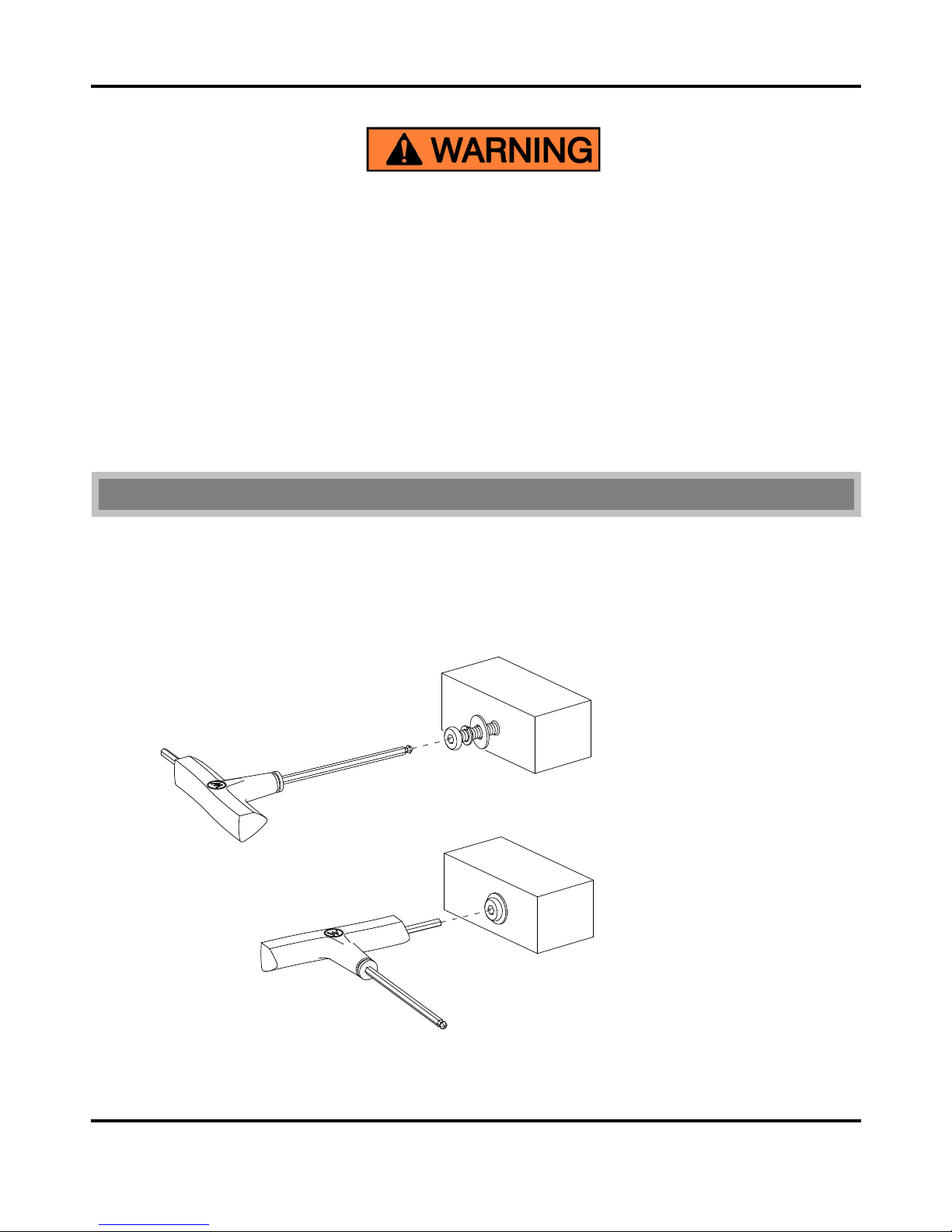
2. Use the long end of the hex wrench to fasten bolts loosely and quickly.
3. Use the short end of the hex wrench for final tightening.
G E N E R A L I N F O R M A T I O N , T I P S A N D T R I C K S
②
①
Page 4

4 Need Assistance? Call us at 1-888-301-0332 from 8am to 5pm CST Monday - Friday
TO HELP PREVENT SERIOUS OR FATAL INJURIES FROM
ENTRAPMENT OR FALLS
Follow the information on the warnings appearing on the upper bunk end
structure and on the carton. Do not remove warning label from bed.
Always use the recommended size mattress or mattress support, or both, to help
prevent the likelihood of entrapment or falls.
Surface of mattress must be at least 5 in. (12.70 cm) below the upper edge of
guardrails.
Do not allow children under 6 years of age to use the upper bunk.
Periodically check and ensure that the guardrail, ladder and other components
are in their proper position, free from damage and that all connectors are tight.
Do not allow horseplay on or under the bed and prohibit jumping on the bed.
Always use the ladder for entering and leaving the upper bunk.
Do not use substitute parts. Contact the manufacturer or dealer for replacement
parts.
Use of a night light may provide added safety precaution for a child using the
upper bunk.
Always use guardrails on both long sides of the upper bunk. If the bunk bed will
be placed next to the wall, the guardrail that runs the full length of the bed
should be placed against the wall to prevent entrapment between the bed and
wall.
The use of water or sleep flotation mattress is prohibited.
STRANGULATION HAZARD – Never attach or hang items to any part of the
bunk bed that are not designed for use with the bed; for example, but not limited
to, hooks, belts, and jump ropes.
Prohibit more than one person on upper bunk.
Keep these instructions for future reference.
This product was manufactured October 2018.
Page 5
Need Assistance? Call us at 1-888-301-0332 from 8am to 5pm CST Monday - Friday 5
Parts and Hardware List
Please read completely through the instructions and verify that all listed parts and hardware are present
before beginning assembly.
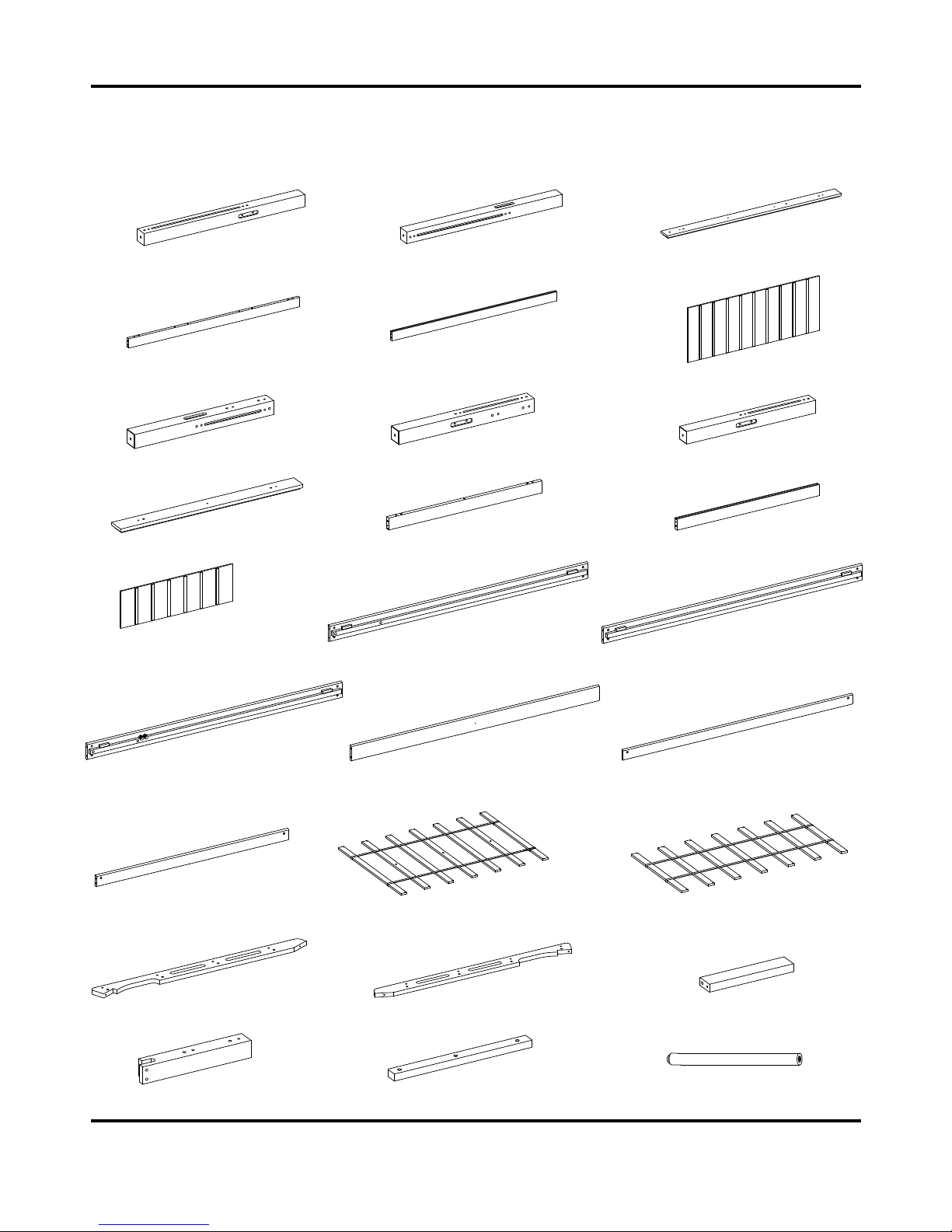
A- Lower Post (Qty. 2) B- Lower Post (Qty. 2) C- Lower Cap Rail (Qty. 2)
D- Lower Top Stretcher (Qty. 2) E- Lower Bottom Stretcher (Qty. 2) F- Lower Panel (Qty. 2)
G- Upper Post (Qty. 2) H- Upper Post (Qty. 1) I- Upper Post (Qty. 1)
J- Upper Cap Rail (Qty. 2) K- Upper Top Stretcher (Qty. 2) L- Upper Bottom Stretcher (Qty. 2)
M- Upper Panel N- Lower Ladder Side Rail O- Lower Mattress Side Rail
(Qty. 2) (Qty. 1) (Qty. 1)
P- Upper Ladder Side Rail Q- Upper Mattress Side Rail R- Long Guardrail
(Qty. 1) (Qty. 1) (Qty. 2)
S- Short Guardrail T- Lower Mattress Support Slats U- Upper Mattress Support Slats
(Qty. 2) (Qty. 1) (Qty. 1)
V- Left Ladder Support (Qty. 1) W- Right Ladder Support (Qty. 1) X- Ladder Step (Qty. 4)
Y- Front Guardrail Post (Qty. 1) Z- Guardrail Support (Qty. 2) AA- Slat Support with Leveler (Qty. 3)
Page 6
6 Need Assistance? Call us at 1-888-301-0332 from 8am to 5pm CST Monday - Friday
Parts and Hardware List
Please read completely through the instructions and verify that all listed parts and hardware are present
before beginning assembly.
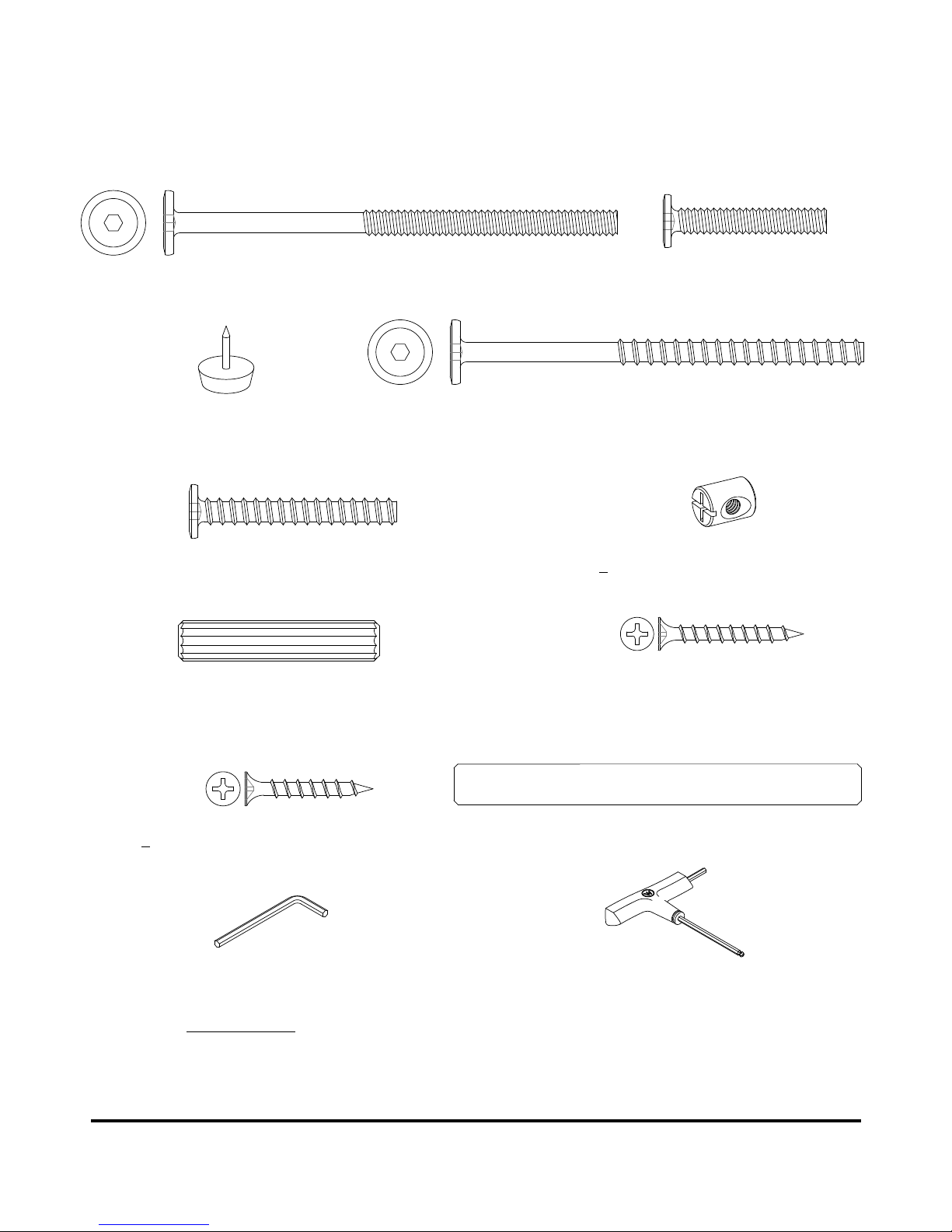
(1) 1/4” x 110 mm Bolt (2) 1/4” x 38 mm Bolt
(Qty. 24+1 extra) (Qty. 5+1 extra)
(3) Floor Protector (4) 6.5 mm x 100 mm Tapping Bolt
(Qty. 4+1 extra) (Qty. 16+1 extra)
(5) 6.5 mm x 48 mm Tapping Bolt (Qty. 26+1 extra) (6) Barrel Nut (Qty. 24+1 extra)
(7) 10 mm x 50 mm Wood Dowel (Qty. 40+2 extra) (8) 4 mm x 35 mm Screw (Qty. 28+1 extra)
(9) 4 mm x 30 mm Screw (Qty. 6+1 extra) (10) Bed Connector Pin (Qty. 4)
L-shaped Hex Wrench (Qty. 1) T-Handle Hex Wrench (Qty. 1)
Tools required: Hex wrench (provided) and Phillips screwdriver (not provided).
Page 7
Need Assistance? Call us at 1-888-301-0332 from 8am to 5pm CST Monday - Friday 7
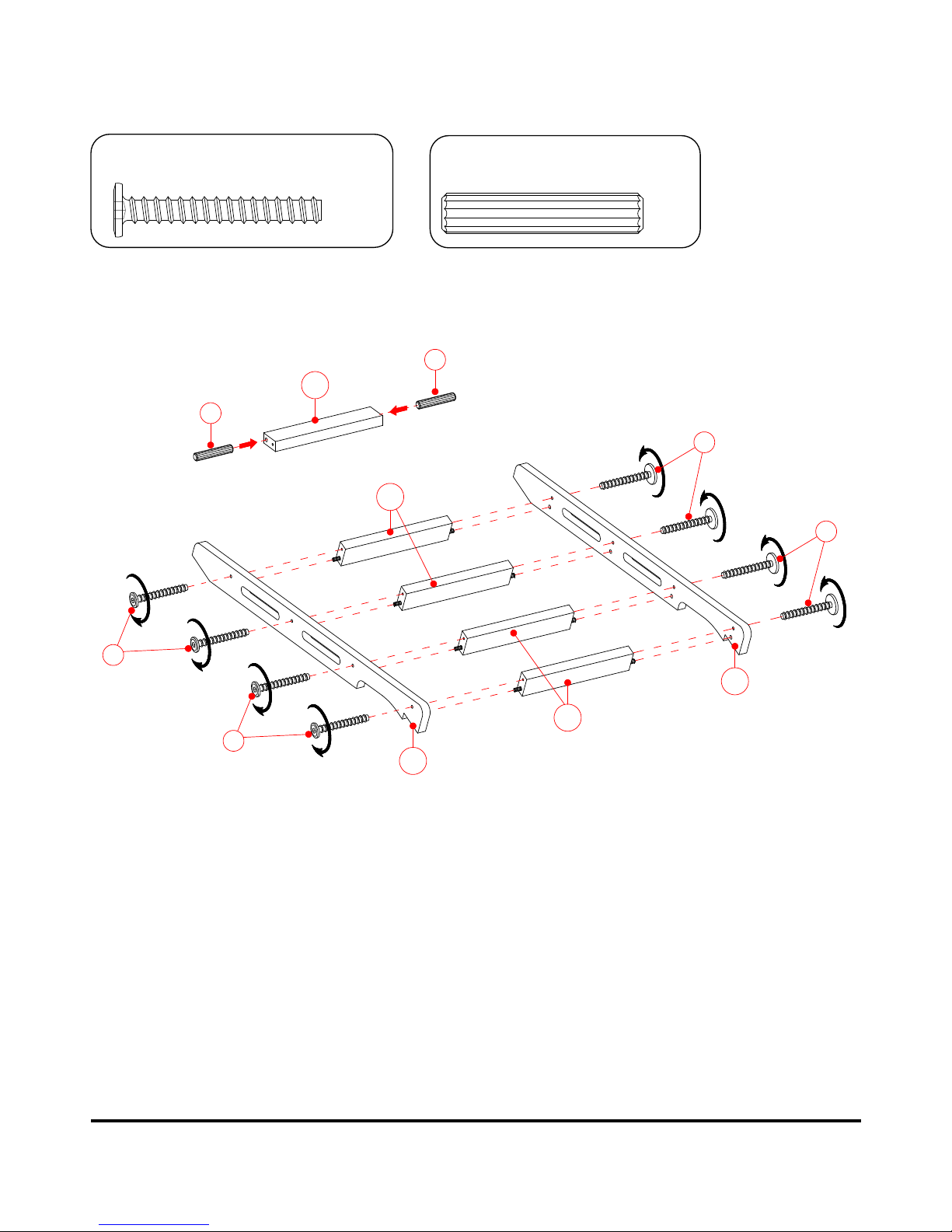
Step 1
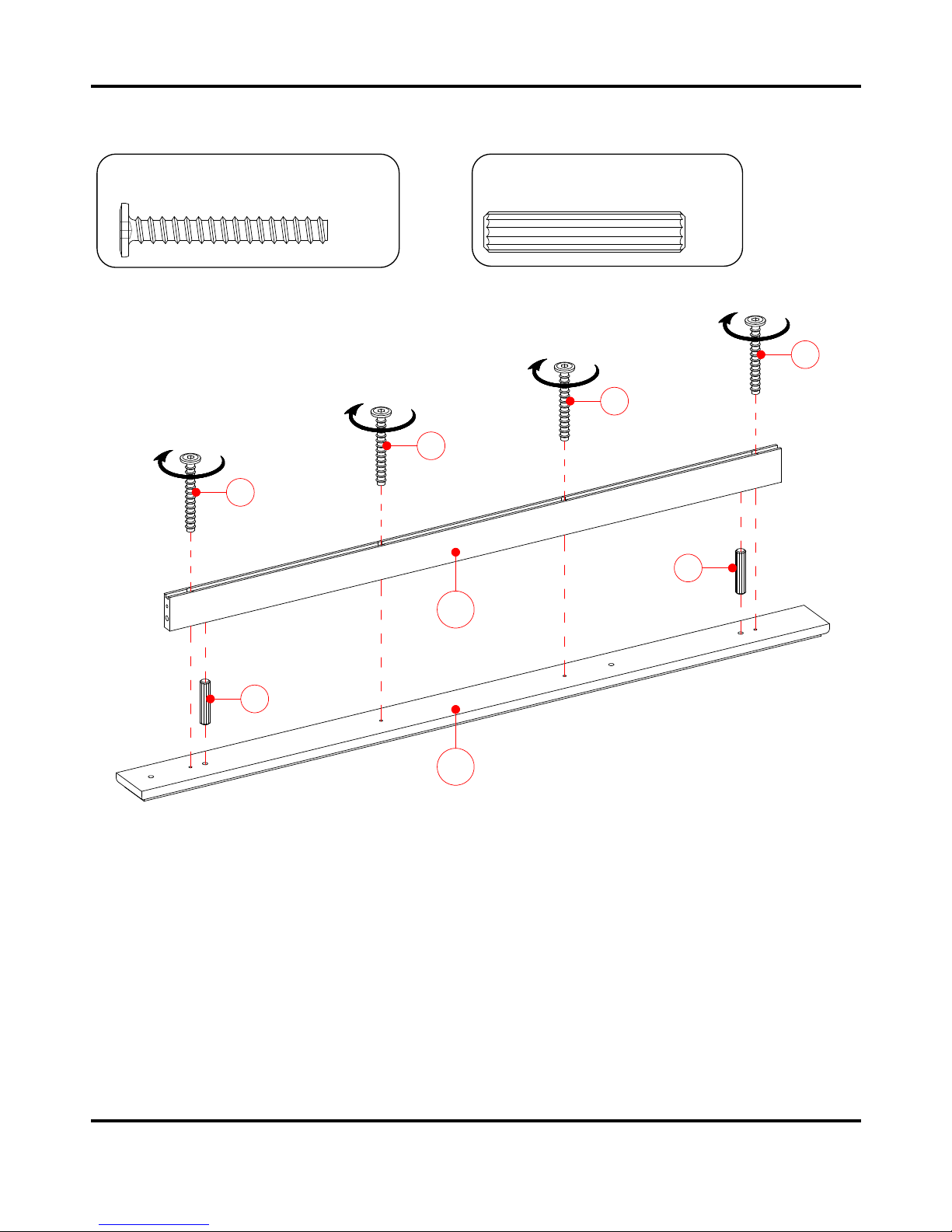
a) Unpack the units and confirm that you have all hardware and required parts.
b) Place one Lower Cap Rail (C) on a level and protected surface with the holes facing up.
c) Insert two Wood Dowels (7) into the large holes of one Lower Top Stretcher (D) and attach to the
Lower Cap Rail (C) using four 48 mm Tapping Bolts (5).
d) Repeat the same process to combine the remaining Lower Cap Rail (C) and Lower Top Stretcher (D)
together.
10 mm x 50 mm Wood Dowel
(4 used in this step)
⑦
6.5 mm x 48 mm Tapping Bolt
(8 used in this step)
⑤
X2
7
D
7
C
5
5
5
5
Page 8
8 Need Assistance? Call us at 1-888-301-0332 from 8am to 5pm CST Monday - Friday
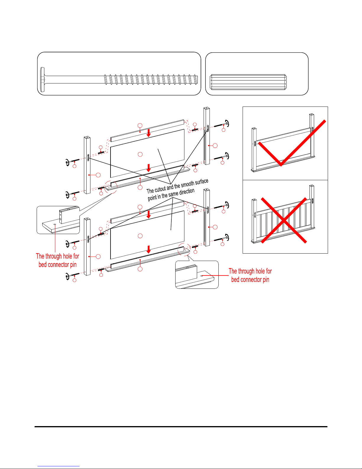
Step 2
a) Fit one Lower Panel (F) between the Lower Stretchers (D and E).
b) Insert four Wood Dowels (7) into the large holes of the Lower Stretchers (D and E) at both ends. Align
and attach the Lower Posts (A and B) to the Lower Stretchers (D and E) and the Lower Panel (F) with
four 100 mm Tapping Bolts (4).
c) Repeat the same process to form the lower footboard.
6.5 mm x 100 mm Tapping Bolt
(8 used in this step)
④
10 mm x 50 mm Wood Dowel
(8 used in this step)
⑦
A
4
4
7
7
D
F
E
B
7
7
4
4
A
4
4
7
7
D
F
E
B
7
7
4
4
Page 9
Need Assistance? Call us at 1-888-301-0332 from 8am to 5pm CST Monday - Friday 9
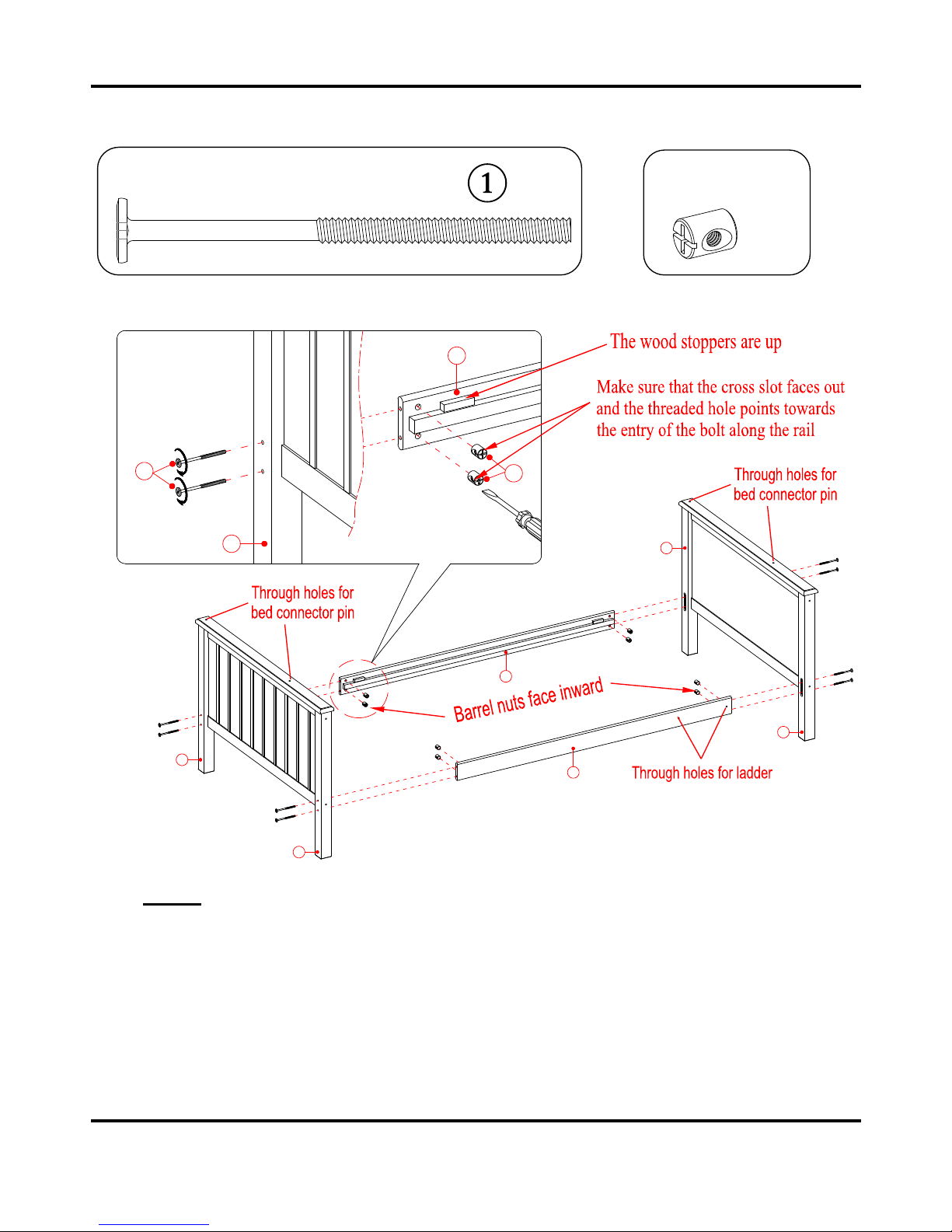
Step 3
NOTE: Please follow the instructions carefully to insure a sa fe and sturdy bed. Do not f ul l y
tigh t en th e b olts un ti l a ll ra il s an d gu ar dr a ils a r e attac he d.
a) Insert 2 Barrel Nuts (6) into each end of the Lower Mattress Side Rail (O) and Lower Ladder Side Rail
(N). Be sure that the cross slot on the Barrel Nut faces out and that the long groove points towards the
entry of the bolt.
b) Bolt the Lower Mattress Side Rail (O) and Lower Ladder Side Rail (N) between the Lower Posts (A
and B) as shown above, using the 110 mm Bolts (1) through the drilled holes on the Posts and screw
into the Barrel Nuts (6) in the Side Rails (O and N). Make s ure t he wo o d sto p pers attached to the
Mattress Side Rail fo r s la t s ar e u p an d fa ce i n ward.
6
1
B
A
B
A
O
N
A
O
1/4” x 110 mm Bolt
(8 used in this step)
Barrel Nut
(8 used in this step)
⑥
Page 10
10 Need Assistance? Call us at 1-888-301-0332 from 8am to 5pm CST Monday - Friday
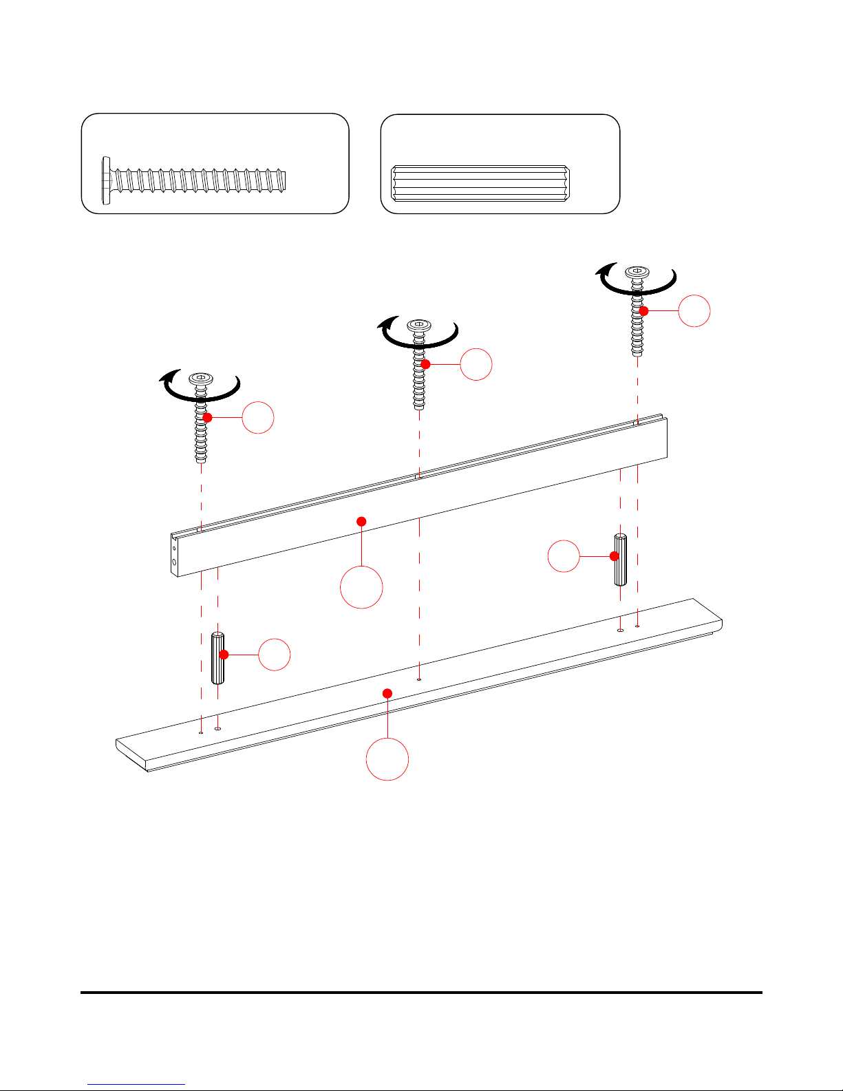
Step 4
a) Place one Upper Cap Rail (J) on a level and protected surface with the holes facing up.
b) Insert two Wood Dowels (7) into the large holes of one Upper Top Stretcher (K) and attach to the
Upper Cap Rail (J) using three 48 mm Bolts (5).
c) Repeat the same process to combine the remaining Upper Cap Rail (J) and Upper Top Stretcher (K)
together.
7
7
5
5
5
J
K
10 mm x 50 mm Wood Dowel
(4 used in this step)
⑦
6.5 mm x 48 mm Tapping Bolt
(6 used in this step)
⑤
X2
Page 11
Need Assistance? Call us at 1-888-301-0332 from 8am to 5pm CST Monday - Friday 11
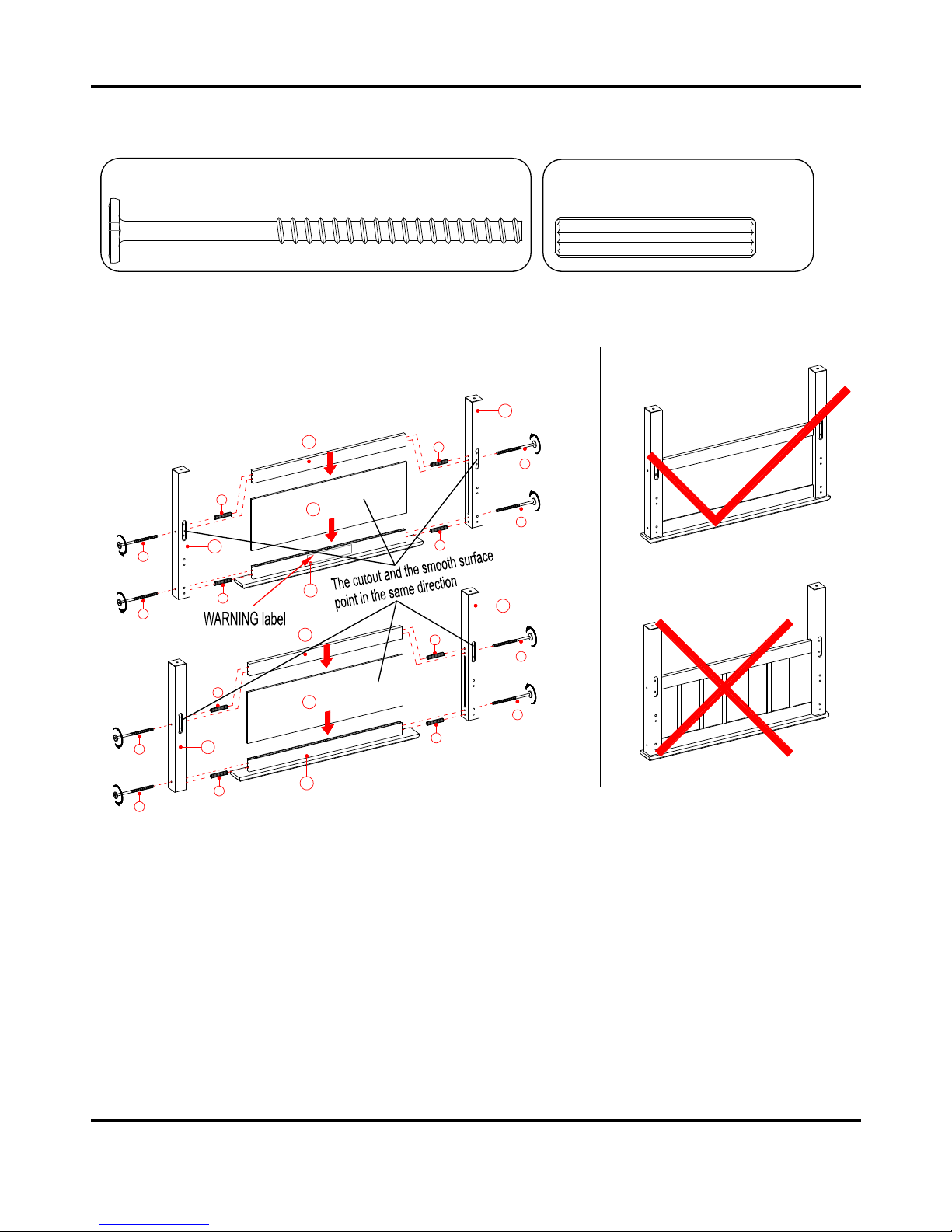
Step 5
Repeat step 2 to form the upper headboard and footboard.
7
4
4
7
7
4
4
7
K
M
L
7
4
4
7
7
4
4
7
K
M
L
I
H
G
G
6.5 mm x 100 mm Tapping Bolt
(8 used in this step)
④
10 mm x 50 mm Wood Dowel
(8 used in this step)
⑦
Page 12
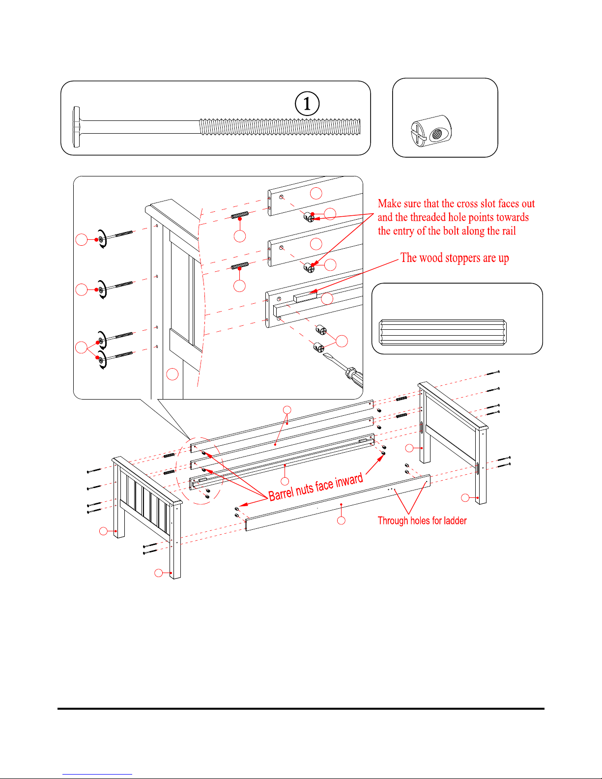
12 Need Assistance? Call us at 1-888-301-0332 from 8am to 5pm CST Monday - Friday
Step 6
a) Insert the Wood Dowels (7) into the drilled large holes of Long Guardrail (R) at both ends. Attach 2
Long Guardrails (R) and the Upper Mattress Side Rail (Q) between the Upper Posts (G and H) using
eight 110 mm Bolts (1) and eight Barrel Nuts (6) as shown above.
b) Attach Upper Ladder Side Rail (P) between the Upper Posts (G and I) using four 110 mm Bolts (1) and
four Barrel Nuts (6). Make sure the wood stoppers for slat attached on side rail are up and face inward.
1/4” x 110 mm Bolt
(12 used in this step)
Barrel Nut
(12 used in this step)
⑥
10 mm x 50 mm Wood Dowel
(4 used in this step)
⑦
R
6
R
6
Q
H
G
I
G
P
Q
R
1
1
1
6
7
7
H
Page 13
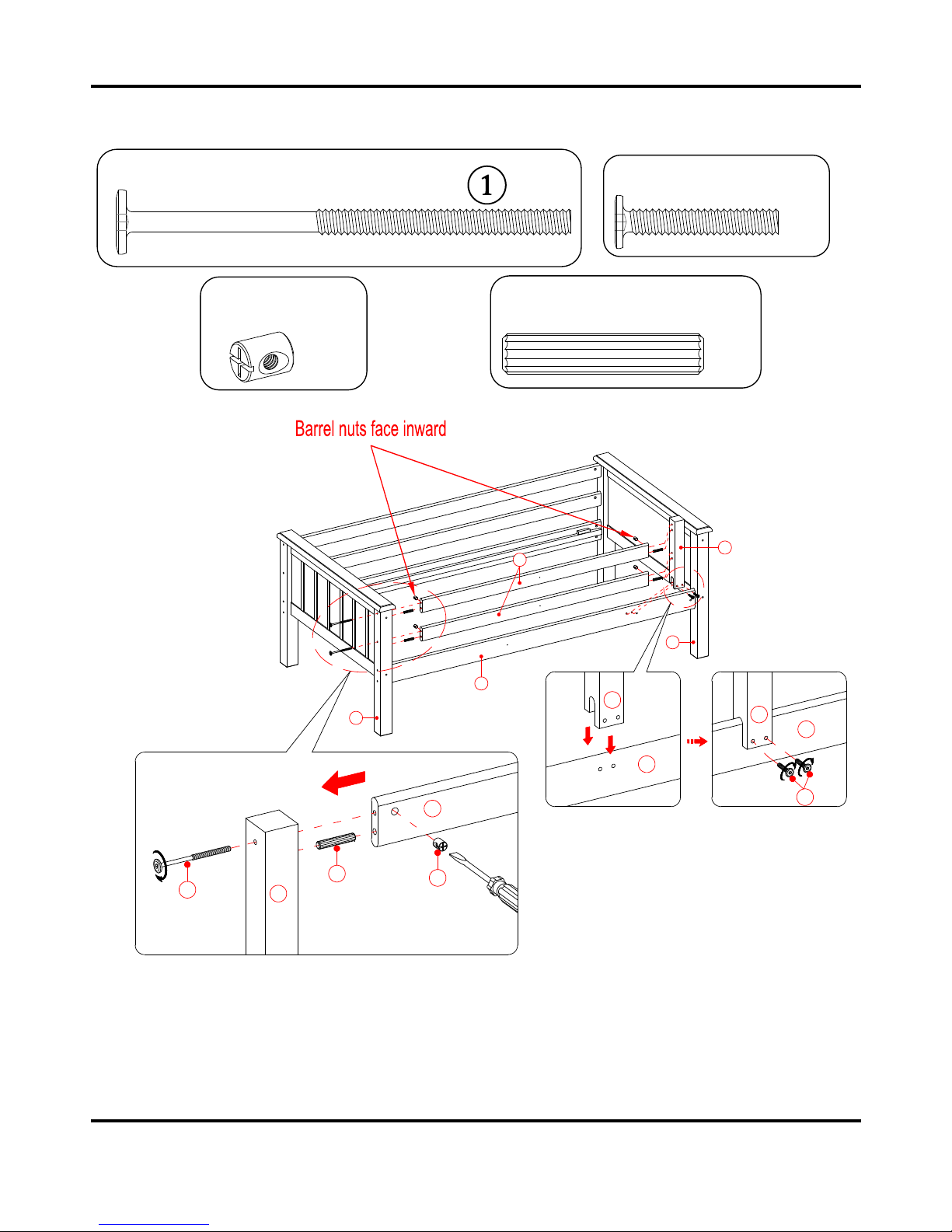
Need Assistance? Call us at 1-888-301-0332 from 8am to 5pm CST Monday - Friday 13
Step 7
a) Insert the Wood Dowels (7) into the end large holes of Short Guardrails (S) as a guide. Attach 2 Short
Guardrails (S) between the Front Upper Post (G) and Front Guardrail Post (Y) using four 110 mm Bolts
(1) and four Barrel Nuts (6).
b) Fasten the Front Guardrail Post (Y) to the Upper Ladder Side Rail (P) with two 38 mm Bolts (2).
Y
P
Y
P
2
S
6
7
1
G
G
I
P
S
Y
1/4” x 38 mm Bolt
(2 used in this step) ②
1/4” x 110 mm Bolt
(4 used in this step)
10 mm x 50 mm Wood Dowel
(4 used in this step)
⑦
Barrel Nut
(4 used in this step)
⑥
Page 14
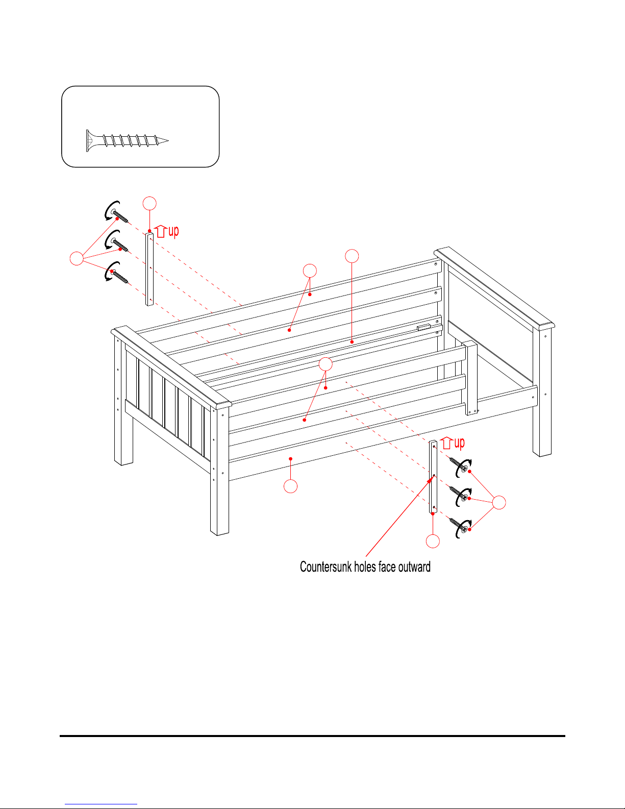
14 Need Assistance? Call us at 1-888-301-0332 from 8am to 5pm CST Monday - Friday
Step 8
a) With the pilot holes as a guide, align and attach one Guardrail Support (Z) to the center of the Long
Guardrails (R) and the Upper Mattress Side Rail (Q) by using three 30 mm Screws (9) through the
countersunk holes and screw into place.
b) Repeat the same procedure to attach the other Guardrail Support (Z) to the Short Guardrails (S) and the
Upper Ladder Side Rail (P).
P
Q
R
S
Z
Z
9
9
4 mm x 30 mm Screw
(6 used in this step)
⑨
Page 15
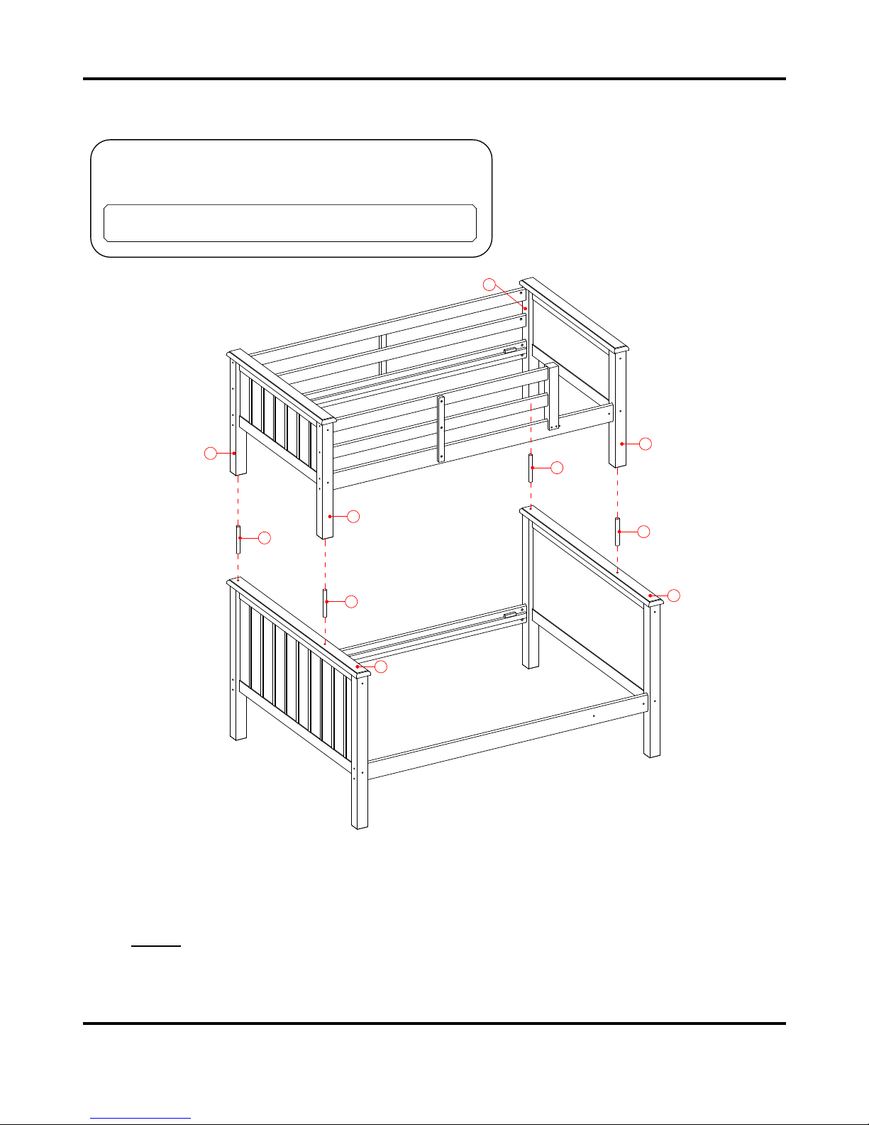
Need Assistance? Call us at 1-888-301-0332 from 8am to 5pm CST Monday - Friday 15
Step 9
a) Now, place the two assembled bunks where you want to place your bunk bed.
b) Insert 4 Bed Connector Pins (10) into the top holes of lower bunk.
c) Now, ask for assistance to stack the upper bunk onto the Bed Connector Pins (10) on the lower bunk.
NOTE: Make sure that the Upper Bunk sits completely on top of the lower bunk and the pins go all the
way, not leaving any gaps.
Bed Connector Pin
(4 used in this step)
⑩
10
10
10
10
I
C
C
G
H
G
Page 16
16 Need Assistance? Call us at 1-888-301-0332 from 8am to 5pm CST Monday - Friday
Step 10
a) Insert the Wood Dowels (7) into the large holes of Ladder Steps (X) at both ends.
b) Attach Left and Right Ladder Supports (V and W) to the Ladder Steps (X) using the 48 mm Tapping
Bolts (5). Securely tighten all bolts with the provided hex wrench.
10 mm x 50 mm Wood Dowel
(8 used in this step)
⑦
6.5 mm x 48 mm Tapping Bolt
(8 used in this step)
⑤
7
7
X
5
X
X
W
V
5
5
5
Page 17
Need Assistance? Call us at 1-888-301-0332 from 8am to 5pm CST Monday - Friday 17
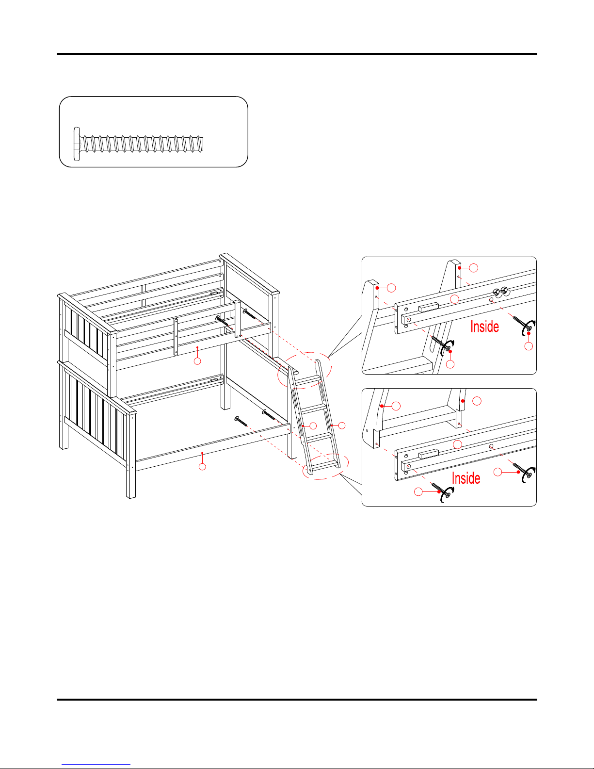
Step 11
Align and attach the assembled Ladder to the Ladder Side Rails (P and N) using the 48 mm Tapping
Bolts (5).
5
V
W
N
P
W
5
V
V
W
5
5
N
P
6.5 mm x 48 mm Tapping Bolt
(4 used in this step)
⑤
Page 18
18 Need Assistance? Call us at 1-888-301-0332 from 8am to 5pm CST Monday - Friday
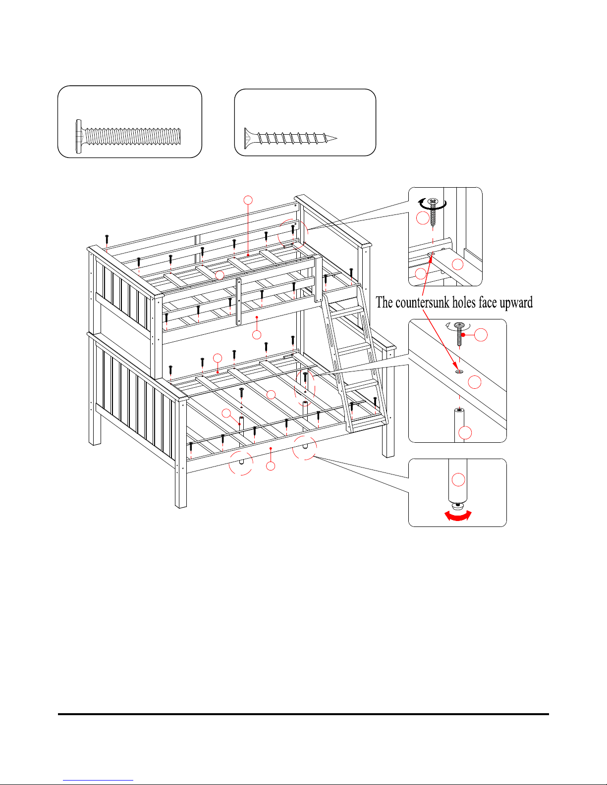
Step 12
a) Lay out the Upper Mattress Support Slats (U) between the wood stoppers on the Upper Ladder Side
Rail (P) and the Upper Mattress Side Rail (Q). Insert and screw 35 mm Screws (8) into the countersunk
holes on each slat. Tighten the screws using a Phillips screwdriver.
b) Attach 3 Slat Supports (AA) to the bottom side of the Lower Mattress Support Slats (T) with three 38
mm Bolts (2). Set the pre-attached floor leveler underneath each Slat Support (AA) to the correct height.
c) Repeat the same process to attach the Lower Mattress Support Slats (T) into place.
4 mm x 35 mm Screw
(28 used in this step)
⑧
P
Q
U
8
U
Q
2
T
AA
T
N
O
AA
AA
1/4” x 38 mm Bolt
(3 used in this step)
②
Page 19
Need Assistance? Call us at 1-888-301-0332 from 8am to 5pm CST Monday - Friday 19
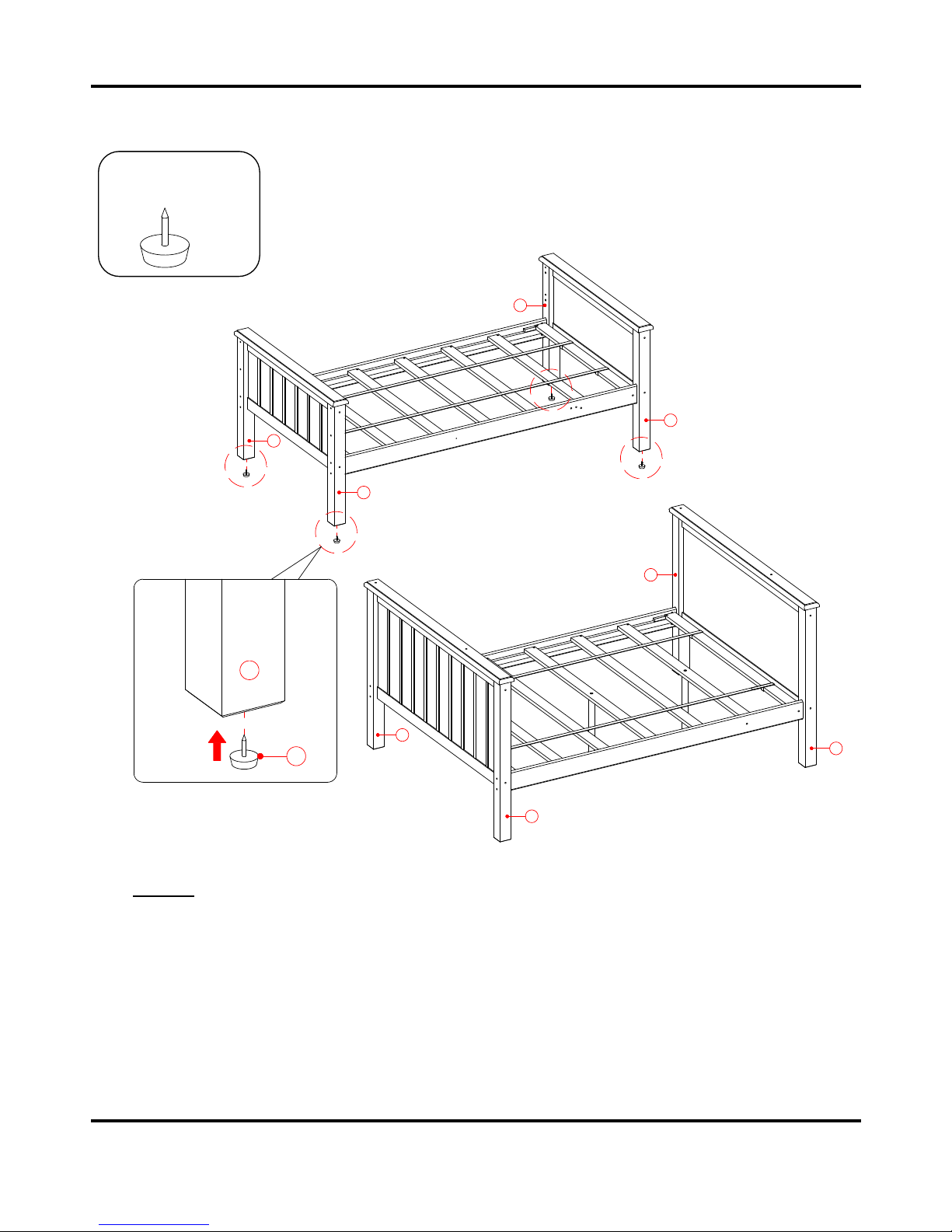
Step 13
NOTE : The bun k be d can be se pa ra t ed in t o a twin bed and a ful l -s i ze b ed . In th is cas e,
atta c h four Floo r Prot ec to r s (3) onto the botto m of t h e Up p er Post s (G, H a n d I)
Guar d ra i ls are n ot nece s s ary.
a) To convert the bunk bed back into a twin bed and a full-size bed, first unscrew the bolts to remove the
Ladder and all Guardrails.
b) Have an assistant help to remove the Upper Bunk from the Lower Bunk.
c) Attach four Floor Protectors (3) to the bottom of the Upper Posts (G, H and I), as shown in the
illustration. The beds can now be placed in the desired locations.
Floor Protector
(4 used in this step)
③
G
3
G
H
I
B
A
B
A
G
 Loading...