

Page 1
Page 2
Condensing Boiler 07/05/99
1
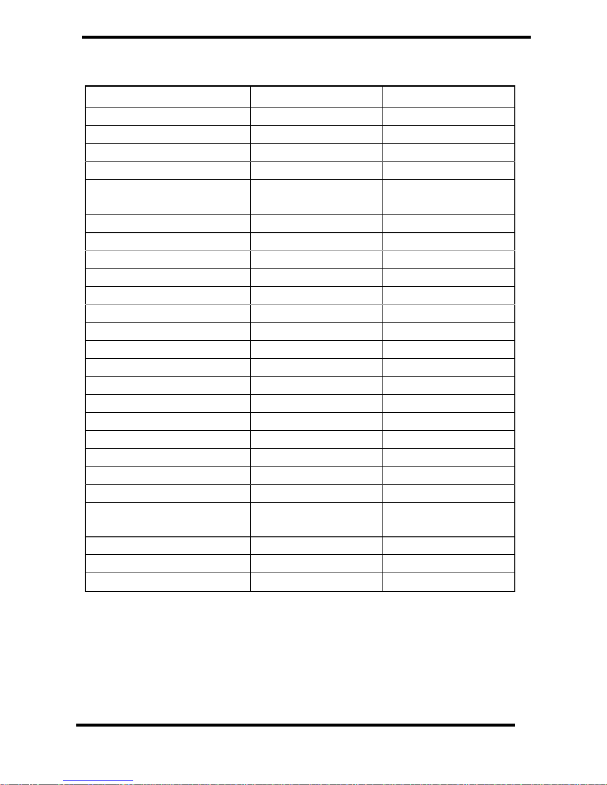
Technical Data
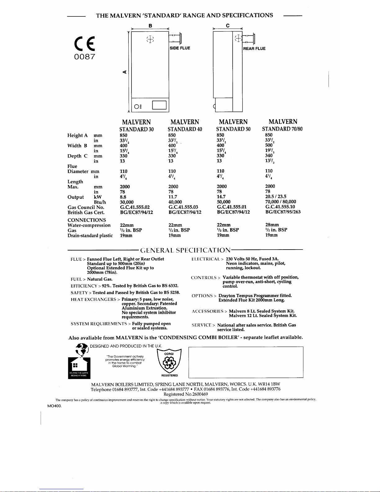
BOILER MODEL 30 40
Heat Input 9.6 kW (32,600 Btu/h) 12.7 kW (43,500 Btu/h)
Heat Output 80 - 60ºC 8.1 kW (27,700 Btu/h) 11.0 kW (37,400 Btu/h)
Heat Output 60 - 40ºC 8.8 kW (30,000 Btu/h) 11.7 kW (40,000 Btu/h)
Setting Pressure, 20mb Line 11.0 mb (4.4 in) 8.0 mb (3.2 in)
Gas Consumption for CV
1015, after 10 minutes
0.892 m³/h
(31.5 ft³/h)
1.198 m³/h
(42.3 ft³/h)
Main Burner Aeromatic AC13/122551 Aeromatic AC13/122550
Gas Control SIT. 083.00.20 SIT. 083.00.20
Burner Injector Dia. 2.5 Dia. 3.2
Pilot Injector SIT. 997.113/33 SIT. 997.113/33
Gas Connection ½” BSP. ½” BSP.
Dry Weight 33 kg 33 kg
Water Content 1.4 litres 1.4 litres
MAXIMUM Static water head 30 m 30 m
MINIMUM Static water head 1 m 1 m
MAXIMUM Flow temperature 82 ºC 82 ºC
Recommended water flow 7 – 9 litres/m 8 – 10 litres/m
MINIMUM water flow 4 litres/m 5 litres/m
Flow & Return connections 22mm Copper 22mm Copper
Electrical Supply 230V ~ 50Hz 40W 230V ~ 50Hz 40W
External fuse rating 3 Amp 3 Amp
Dimensions mm 850 high 400 wide 330 deep 850 high 400 wide 330 deep
Service clearances mm 450 front 30 above 100
below 75 left & right
450 front 30 above 100
below 75 left & right
Terminal dimensions mm
160 high 160 wide 55 deep 160 high 160 wide 55 deep
Flue diameter mm 110 110
Flue length, min – max, mm 100 - 2000 100 - 2000
Page 3
Condensing Boiler 07/05/99
2
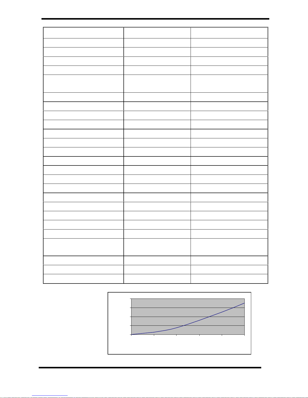
0
100
200
300
400
0 5 10 15 20 25
litres/min
mbar
BOILER MODEL 50 70/80 (min/max)
Heat Input 15.9 kW (54,300 Btu/h)
22.2-25.5 kW (75,750–87,000 Btu/h)
Heat Output 80 - 60ºC 13.7 kW (46,700 Btu/h) 19.1-22.0 kW (65,200–74,800 Btu/h)
Heat Output 60 - 40ºC 14.7 kW (50,000 Btu/h)
20.6-23.5 kW (70,000–80,000 Btu/h)
Setting Pressure, 20mb Line 12.6 mb (5.1in) 10.4 – 14.0 mb (4.2 – 5.6 in)
Gas Consumption for CV
1015, after 10 minutes
1.487 m³/h
(52.5 ft³/h)
2.08 – 2.4 m³/h
(73.5 – 85.7 ft³/h)
Main Burner, Aeromatic AC13/122550 AC13/122553
Gas Control SIT. 083.00.20 SIT. 083.00.20
Burner Injector Dia. 3.2 Dia. 4.1
Pilot Injector SIT. 997.113/33 SIT. 997.113/33
Gas Connection ½” BSP. ½” BSP.
Dry Weight 33 kg 37 kg
Water Content 1.4 litres 1.6 litres
MAXIMUM Static water head 30 m 30 m
MINIMUM Static water head 1 m 1 m
MAXIMUM Flow temperature 82 ºC 82 ºC
Recommended water flow 10 – 12 litres/m 14 – 16 litres/m
MINIMUM water flow 5 litres/m 5 litres/m
Flow & Return connections 22mm Copper 28mm Copper
Electrical Supply 230V ~ 50Hz 40W 230V ~ 50Hz 40W
External fuse rating 3 Amp 3 Amp
Dimensions mm 850 high 400 wide 330 deep 850 high 500 wide 340 deep
Service clearances mm
450 front 30 above 100
below 75 left & right
450 front 30 above 100 below 75
left & right
Terminal dimensions mm 160 high 160 wide 55 deep 160 high 160 wide 55 deep
Flue diameter mm 110 110
Flue length, min – max, mm 100 - 2000 100 – 2000
Pressure loss
All models
Page 4

Condensing Boiler 3 7/5/99
INTRODUCTION
These Instructions cover a range of lightweight,
wall hung, gasfired, condensing boilers. The
flue system is roomsealed and fan assisted on
the flue side. The ignition system is fully
automatic.
There are several models with different outputs
- see table for details. An internal programmer
kit is available as an option.
The boiler casing is of white enamelled mild
steel.
The boilers are suitable for connection to open
vented or sealed systems. These systems may
be pumped central heating or pumped central
heating combined with a pumped indirect
domestic hot water circuit. Gravity circuits must
NOT be used.
Adequate arrangements for completely
draining the system, by provision of drain
cocks MUST be provided.
Gas Safety (Installation and Use)
Regulations, 1984 (as amended).
It is the law that all gas appliances are installed
by a competent person (e.g. a CORGI
registered operative) in accordance with the
above Regulations. Failure to install appliances
correctly could lead to prosecution.
It is in your own interest, and that of safety, to
ensure that the law is complied with. The
installation of the boiler MUST also be in
accordance with the current I.E.E.. Wiring
Regulations, the Local Building Regulations,
Building Standards (Scotland), the Bye Laws of
the Local Water Undertaking, any relevant
requirements of the Local Authority, and Health
and Safety document No 635, "Electricity at
Work Regulations 1989".
Detailed recommendations are contained in the
following British Standard Codes of Practice.
Codes of Practice.
BS.6798 Installation of gas fired hot water
boilers of rated input not exceeding 60kW.
BS.5449:1 Forced circulation hot water
systems (small bore and microbore domestic
central heating systems).
BS.5546 Installation of gas hot water supplies
for domestic purpose (2nd Family Gases).
BS.5440:1 Flues (for gas appliances of rated
input not exceeding 60kW).
BS.5440:2 Air supply (for gas appliances of
rated input not exceeding 60kW).
BS 6891 Specification for installation of low
pressure gas pipework.
BS 7074:1 Application, selection and
installation of expansion vessels and ancillary
equipment for sealed water systems.
IMPORTANT. It is important that no external
control devices are directly connected to this
appliance - unless covered by these
'Installation and Servicing Instructions' or
otherwise recommended by the manufacturer.
If in doubt please enquire.
Any direct connection of a control device not
recommended by the manufacturer could
infringe the Gas Safety (Installation & Use)
Regulations, the above regulations and the
normal appliance warranty.
Manufacturer's notes must NOT be taken, in
any way, as overriding statutory obligations.
LOCATION OF BOILER
The boiler MUST be installed on a flat and
vertical non-combustible wall, capable of
adequately supporting the weight of the boiler
and any ancillary equipment.
THE BOILER IS NOT SUITABLE FOR
EXTERNAL INSTALLATION.
IMPORTANT NOTICE.
If the boiler is to be fitted in a timber framed
building it should be fitted in accordance with
the British Gas publication `Guide for Gas
Installations in Timber Frame Housing',
reference DM2. If in doubt, advice must be
sought from the Local Gas Region of British
Gas.
The boiler may be installed in any room or
internal space, although particular attention is
drawn to the requirements of the current I.E.E.
Wiring regulations and, in Scotland, the
electrical provisions of the Building Regulations
applicable to Scotland with respect to the
installation of the boiler in a room or internal
space containing a bath or shower.
Page 5

Condensing Boiler 4 7/5/99
Where a room sealed appliance is installed in
a room containing a bath or shower then the
appliance and any electrical switch or
appliance control, utilising mains electricity
should be so situated that it cannot be touched
by a person using the bath or shower.
Where installation will be in an unusual
location then special procedures may be
necessary and BS.6798 gives detailed
guidance on this aspect.
A compartment used to enclose the boiler
MUST be designed and constructed specially
for this purpose. An existing cupboard, or
compartment, may be used provided it is
modified for the purpose. Details of essential
features of cupboard compartment design,
including airing cupboard installations are
given in BS.6798.
In siting the boiler, the following limitations
MUST be observed:
1. The position selected for installation MUST
allow adequate space for servicing in front of
the boiler and for air circulation around the
boiler.
2. This position MUST also permit the provision
of a satisfactory balanced flue termination.
3. This position MUST also permit the provision
of a satisfactory connections to the condensate
drain.
GAS SUPPLY
The Local Gas Region should be consulted, at
the installation planning stage, in order to
establish the availability of an adequate supply
of gas.
An existing service pipe must NOT be used
without prior consultation with the Local Gas
Region, or by a local Gas region contractor. An
existing meter should be checked preferably by
the Gas region, to ensure that the meter is
adequate to deal with the rate of gas supply
required.
Installation pipes should be fitted in
accordance with BS.6891: 1988.
Do NOT use pipes of a smaller size than the
boiler inlet gas connection.
FLUEING
Detailed recommendations for flueing are given
in BS.5440: 1.
The following notes are intended for general
guidance.
1. Be aware of the plume from the flue and the
wetting effect it has to adjacent property.
2. The flue can be taken to the left, right or rear
of the appliance.
3. The boiler is provided with standard flue kit
that will reach 500mm (20 in). An extended flue
kit is available which enables the flue to be
extended straight to 2000mm (79 in), Part No
7721). The air duct must be supported every
700mm (30 in) with the clips provided.
4. The boiler MUST be installed so that the
terminal is exposed to external air.
5. It is important that the terminal allows the
free passage of air across it at all times.
6. The acceptable spacing from the terminal to
obstructions and ventilation openings are
specified in Table 1.
7. Where the lowest part of the terminal is
fitted less than 2m (6.6ft.) above a balcony,
above ground, or above a flat roof to which
people have access then the terminal MUST
be protected by a purpose designed guard.
Terminal guard Model K3 6.5 x 11 (plastic
coated) (GC No 393554) is available from:-
Tower Flue Components Ltd.
Tower House.
Vale Rise.
Tonbridge
KENT
TN9 1TB
0732 351555
Page 6
Condensing Boiler 5 7/5/99
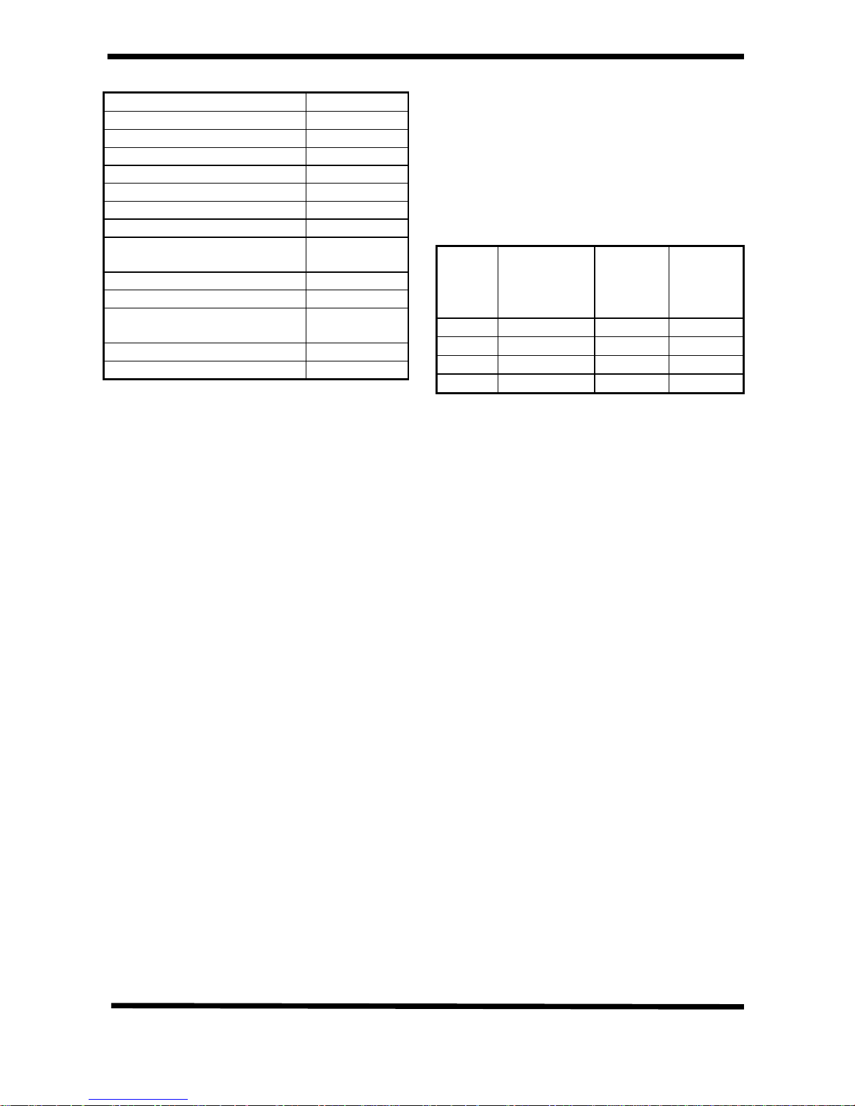
Terminal Position Minimum
Below window or vent 300mm
Below gutter or pipes 75mm
Below eaves 200mm
Below balcony or roof 200mm
From a window 200mm
From vertical pipe 75mm
From corners 300mm
Above ground, roof or
balcony
300mm
From facing surface 600mm
From facing terminal 1200mm
From opening under a car
port
1200mm
Vertically from a terminal 1500mm
Horizontally from a terminal 300mm
Table 1.
IMPORTANT. It is absolutely ESSENTIAL to
ensure, in practice, that products of
combustion discharging from the terminal
cannot re-enter the building, or any other
adjacent building, through ventilators, windows,
doors, other sources of natural air infiltration or
forced ventilation/air conditioning.
If this should occur, the appliance MUST be
turned OFF IMMEDIATELY and the Local Gas
Region consulted.
TERMINAL
The terminal assembly of the balanced flue
can be adapted to accommodate various wall
thickness’ from 100mm to 2000mm. If a
terminal guard is fitted, then the terminal must
be central.
Note. Reference for the terminal position can
be made from Table 1.
AIR SUPPLY
Detailed recommendations for air supply are
given in BS.5440 Pt. 2. The following notes
are intended for general guidance.
It is NOT necessary to have a purpose
provided air vent in the room or internal space
in which the boiler is installed.
If the boiler is to be installed in a cupboard or
compartment, permanent air vents are required
(for cooling purposes) in the cupboard or
compartment, at both high and low levels.
The air vents must either communicate with a
room/internal space, or vent directly outside.
Vents required for a cupboard/compartment
are specified in Table 2, and are related to the
maximum rated heat input of the boiler.
Model Position of
vent
Air from
room
Air
direct
from
outside
30 High & Low
88 cm² 44 cm²
40 High & Low
114 cm² 57 cm²
50 High & Low
144 cm² 72 cm²
80 High & Low
230 cm² 115 cm²
Table 2.
Note: Both air vents MUST communicate with
the same room or internal space, or, MUST
both be on the same wall to outside air.
WATER SUPPLY
The central heating system should be in
accordance with the relevant recommendations
given in BS.6798, BS 7593:1992 and, in
addition, for smallbore and microbore systems
- BS.5449:1.
The domestic hot water system, if applicable,
should be in accordance with the relevant
recommendations of BS.5546.
Copper tubing to BS 2871:1 is recommended
for water carrying pipework.
The hot water storage cylinder MUST be of the
indirect type and should preferably be
manufactured of copper.
The hot water cylinder, & ancillary pipework,
not forming part of the useful heating surface
should be lagged, to prevent heat loss and any
possible freezing, particularly where pipes run
through roof spaces and ventilated underfloor
spaces.
Draining taps MUST be located in accessible
positions, which permit the draining of the
whole system, including boiler and hot water
Page 7
Condensing Boiler 6 7/5/99
storage vessel. Draining taps should be at
least ½ in. nominal size and be in accordance
with BS.2879.
CONDENSATE DRAIN.
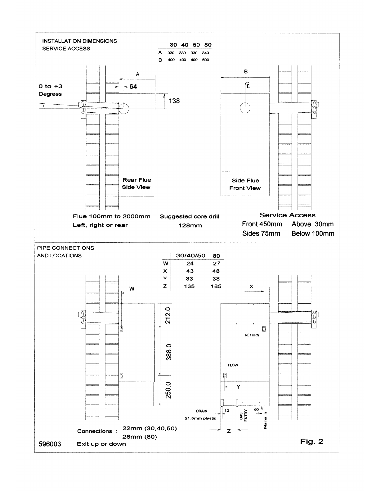
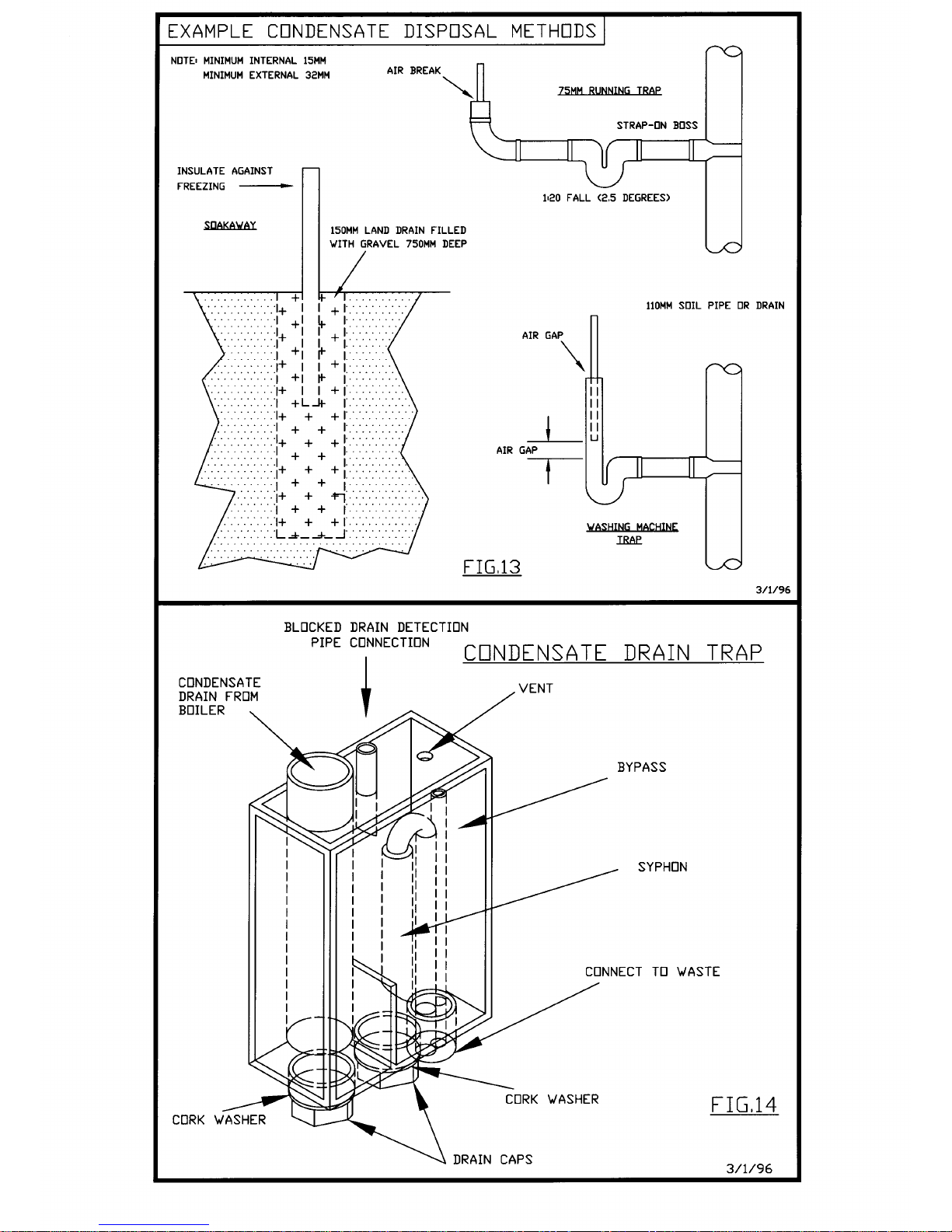
Refer to Fig. 2, and 13.
A condensate drain is provided on the boiler,
this drain must be connected to the household
drainage point, or soakaway on site. All
pipework and fittings in the condensate
drainage system MUST be made of plastic.
Refer to British Gas publication "Guidance
notes for installation of domestic condensing
boilers"
No other materials may be used.
The drain outlet on the boiler is :
Polypipe, 21.5mm pushfit overflow pipe.
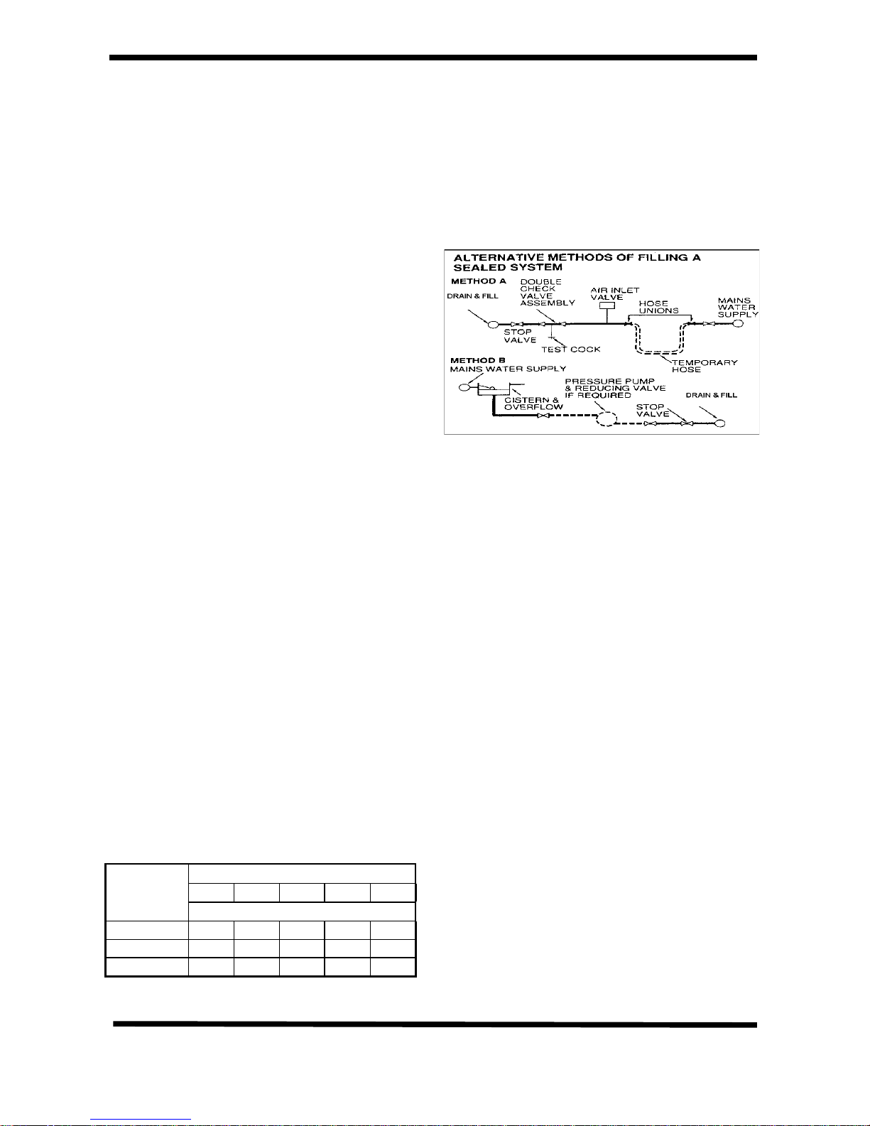
SEALED SYSTEMS
A sealed system should follow the guidelines
given in the Code of Practice BS 7074 :1. It
should include a safety valve to BS 6750 Pt 1.
fitted close to the boiler, without an
intermediate valve to the system and in a
position where it can be tested. It should be
pre—set to operate at 3 bar (45 lb./in²) and
sited to discharge through a pipe to a safe
outlet.
An expansion vessel complying with BS 4814
must be fitted to the system close to the return
side of the pump. The connection should be
not less than 15mm and without a valve or
restriction. Size the vessel by using the graph
below.
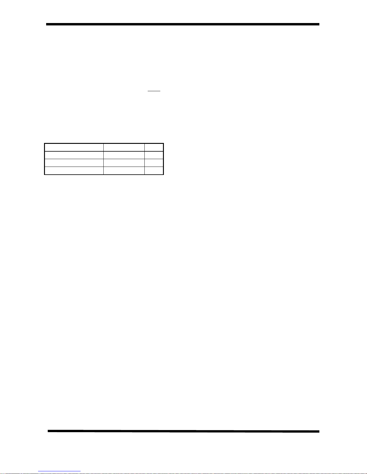
1. Choose a vessel pressure by taking the
static head of the system, adding 0.3 bar,
and taking the nearest larger size.
2. Select the Vessel Volume from the table
below by finding the system volume and
vessel pressure.
3. Choose that size or larger from the
manufactures’ range.
Vessel System Volume litres
pressure
50 60 70 100 150
Bar Vessel Volume
0.5 4 4 8 8 12
1.0 8 8 8 12 18
1.5 8 12 12 18 24
A pressure gauge with a fill pressure indicator
and a range of 0-4 bar should be fitted close to
the expansion vessel in a visible position.
A design as detailed below should be used for
the filling connection, it utilises a BS 1010 stop
valve, a double non-return valve and filling loop
fitted at low level and should be installed with
the approval of the local Water Undertaking.
ELECTRICITY SUPPLY.
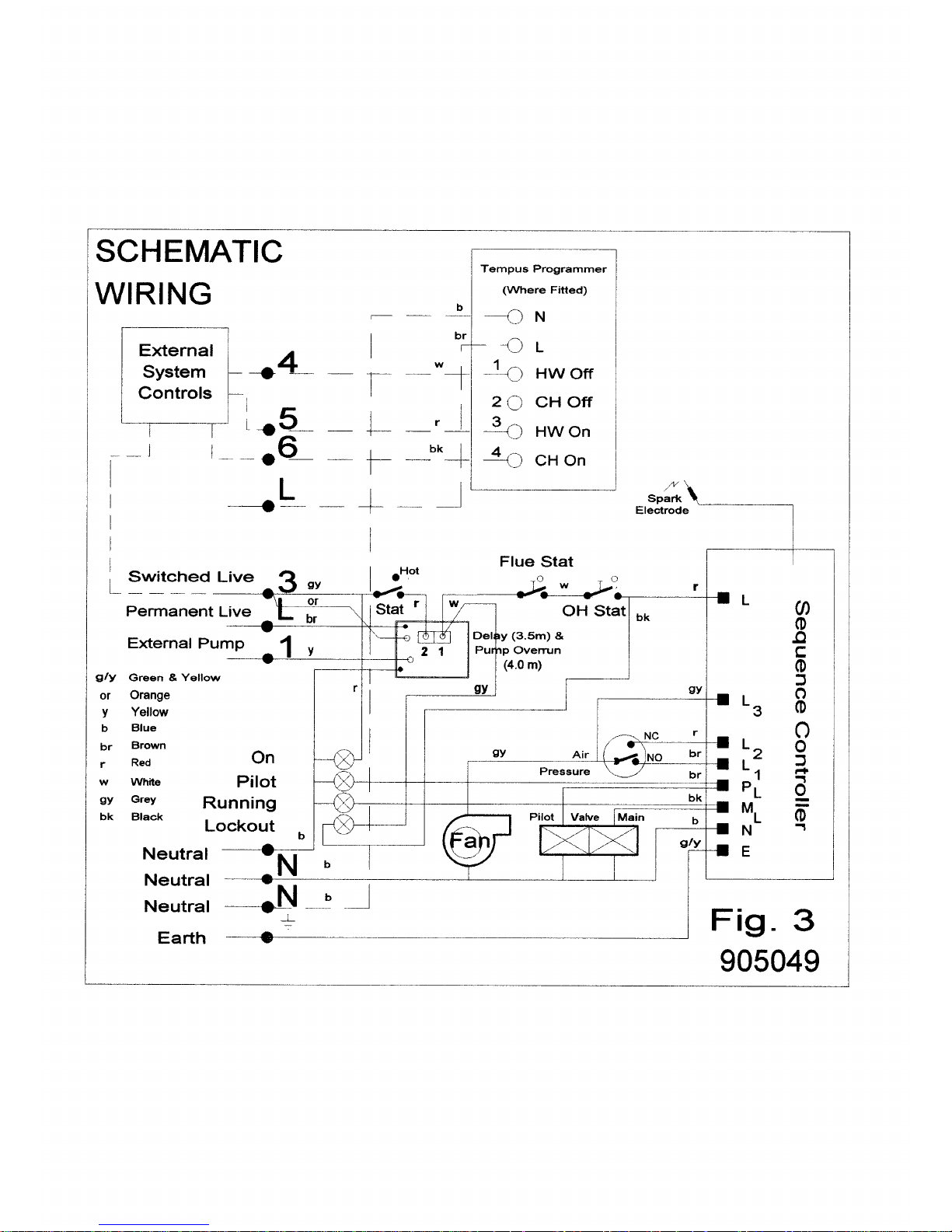
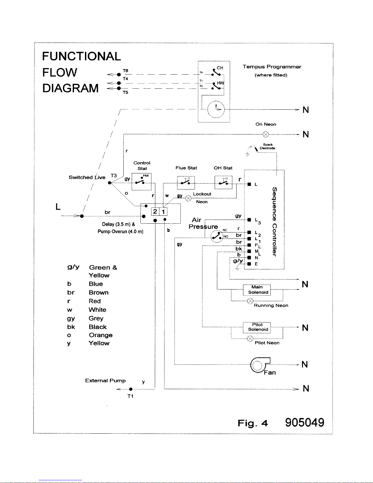
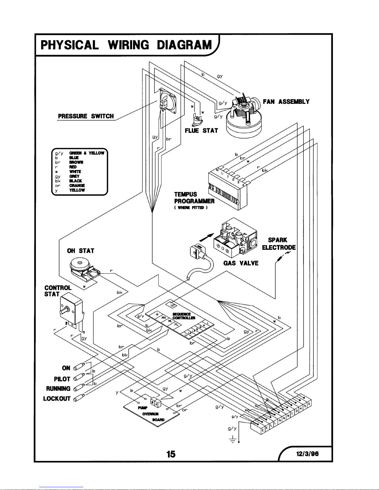
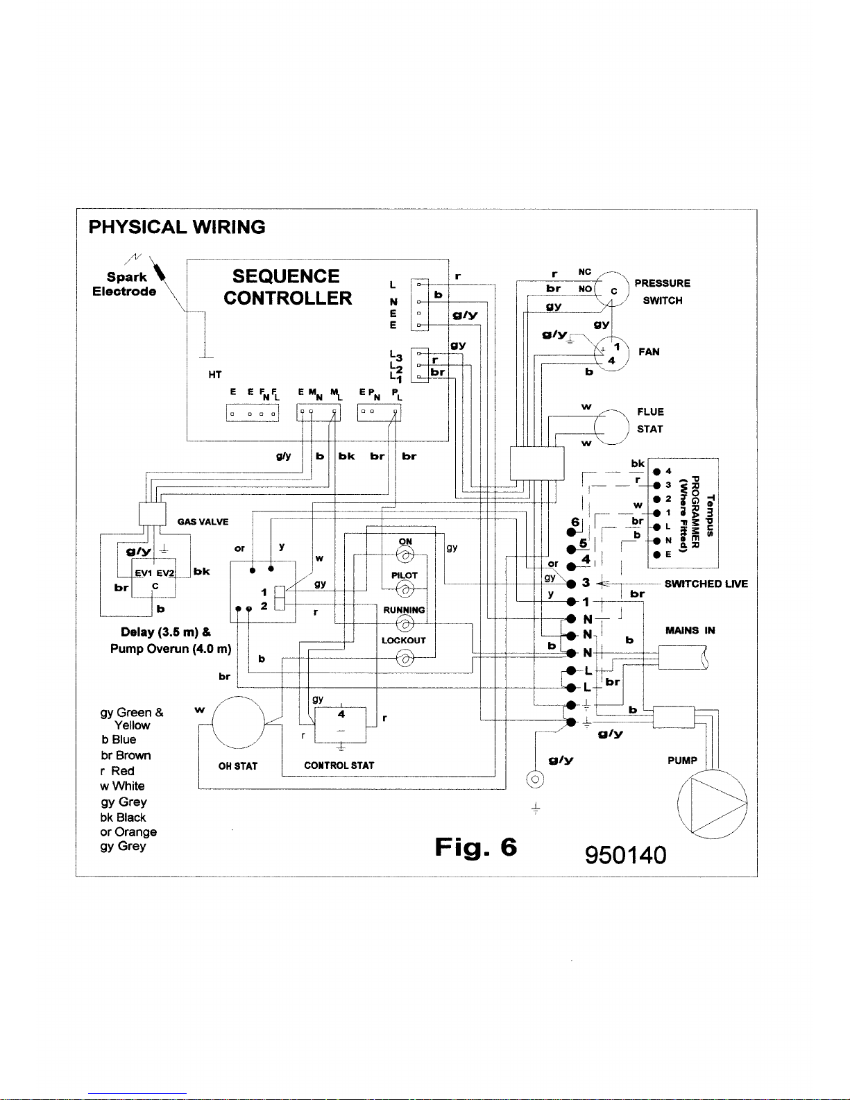
Refer to Figs. 3, 4, 5, and 6.
Wiring external to the appliance MUST be in
accordance with the current I.E.E..
Wiring Regulations and any Local Regulations
which apply.
The boiler is supplied for 230V ~ 50Hz. Single
phase. Fuse rating is 3A.
The method of connection to the mains
electricity supply MUST facilitate complete
electrical isolation of the boiler, preferably by
the use of a fused double pole switch having a
3mm (1/8in.) contact separation in both poles
and servicing only the boiler and system
controls.
The point of connection to the mains should be
readily accessible and adjacent to the boiler,
except that, for bathroom installations, the
point of connection to the mains MUST be
situated outside the bathroom.
Note. Where a room sealed appliance is
installed in a room containing a bath or shower,
the appliance, any electrical switch or
appliance control utilising mains electricity
should be so situated that it cannot be touched
by a person using the bath or shower.
Page 8
Condensing Boiler 7 7/5/99
INSTALLATION OF BOILER
Suggested procedure:
1. Site to suit system and terminal limitations.
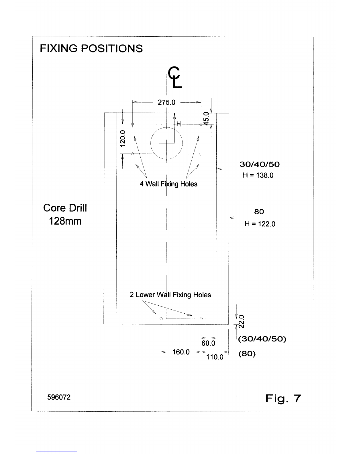
2. Mark fixing and flueing positions (Fig. 7).
3. Drill flue hole.
4. Fix boiler turning box to the wall.
5. Remove the case from boiler module
6. Plumb module for water and gas OFF the
wall (access is much better).
7. Fix module to turning box and the wall.
8. Plumb tails to system and gas.
9. Test for leaks.
Space Required for Installation and Service.
Right or Left 75 mm 3 in
Above 30mm 1in.
Below 100mm. 4in.
In Front 450mm. 18in
REMOVAL OF THE CASE
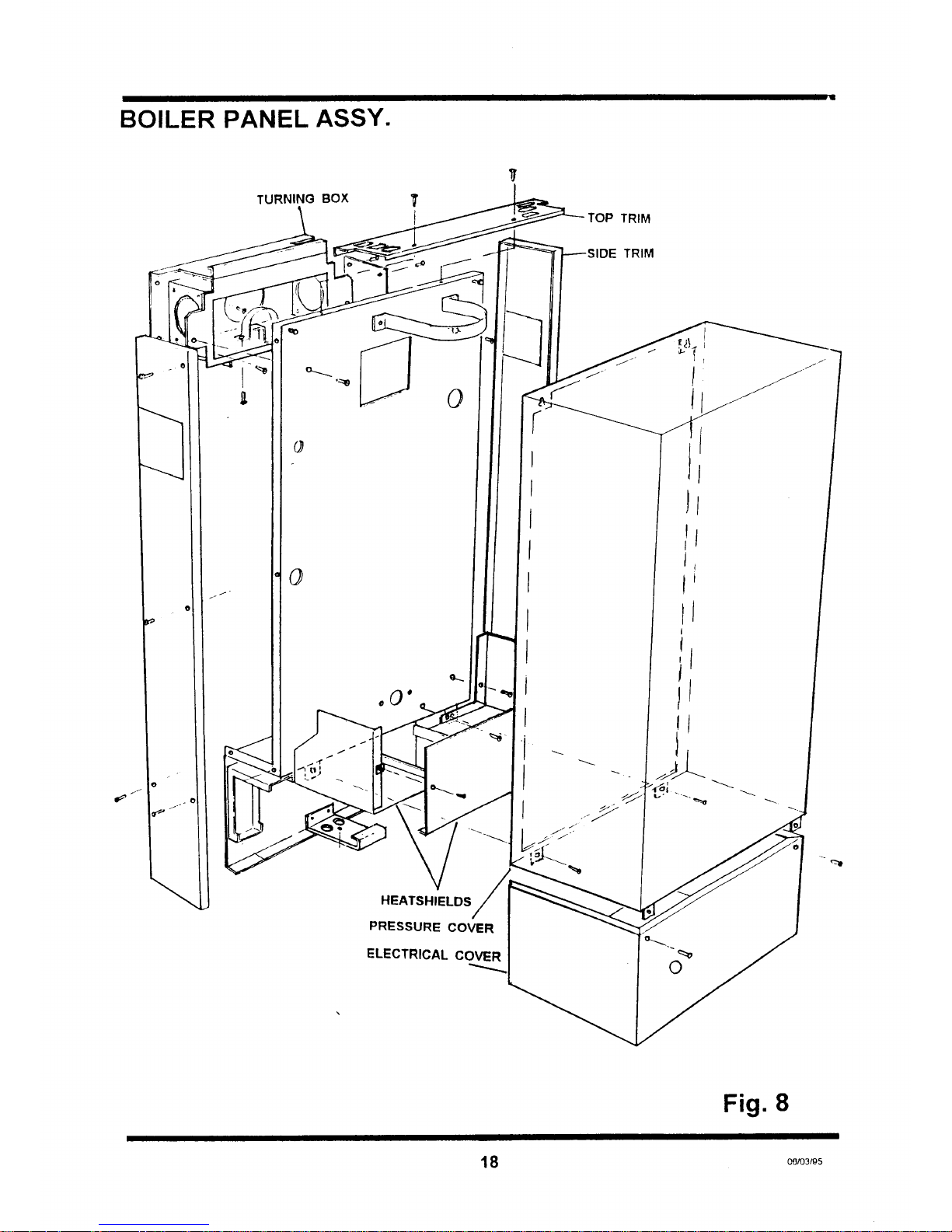
Refer to Fig. 8
1. Lower the electrical cover. This is detached
by unscrewing the two pozidrive screws
located at the top of the control panel,
pulling the cover towards you and carefully
lowering. Care should be taken to prevent
strain on the cables and connections.
2. Remove the case by unscrewing the two
pozidrive screws located at the bottom and
rear of the case, and lifting and pulling
forward off the two pegs which are located
at the top. The case should be kept vertical
as it is removed. Examine the sealing strip
for damage and replace if necessary.
IMPORTANT: FAILURE TO CORRECTLY
LOCATE THE APPLIANCE CASE COULD
RESULT IN LEAKAGE OF COMBUSTION
PRODUCTS INTO THE ROOM.
TURNING BOX
1. Screw the turning box to the wall with the
four screws and rawlplugs supplied. Ensure
that the top of the turning box is level and at
the desired height for the top of the boiler.
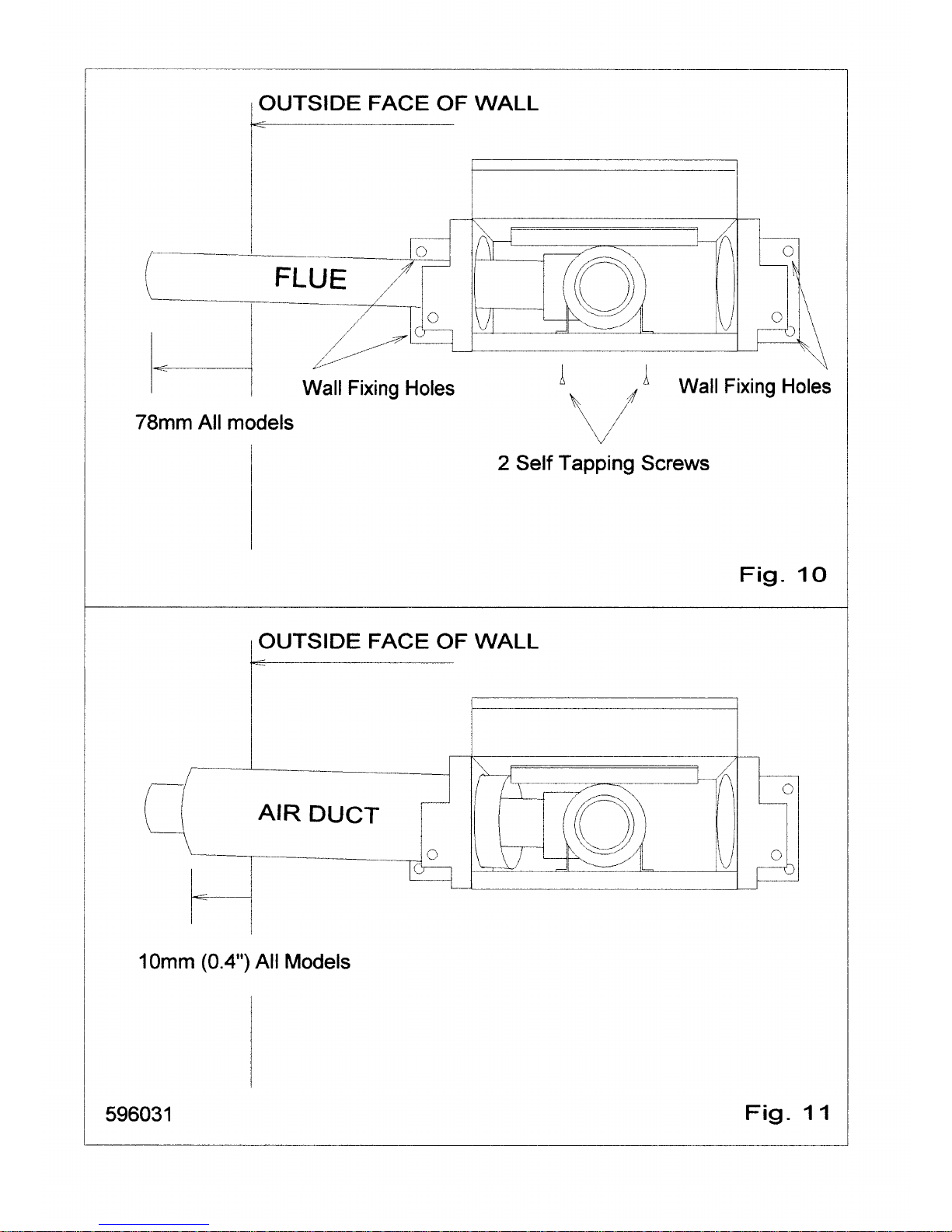
See Fig.10.
2. Prepare the turning box for the required flue
outlet. For rear entry use as supplied. For
left or right outlet, remove appropriate
blanking plate and assemble on rear outlet.
Note: Blanking plate holes should be left with a
screw, to seal them.
ASSEMBLY OF FLUE PIPE AND AIR
DUCT PIPE TO TURNING BOX
Mark wall for flue outlet then core drill to give a
0 to 3 degree slope down towards the boiler.
120mm for all models. (The following is based
on the flue tube being supplied with the straight
and elbow connectors being pre-assembled,
the one NOT required to be cut off during
installation.)
Right or Left Outlet
1. Using the saddle clamp secured with two
self-tapping screws to clamp the 50mm flue
tube with ELBOW CONNECTOR in turning
box. See Fig.10.
2. Measure carefully and saw off the 50mm
tube to give required projection from wall.
See Fig.10.
3. Temporarily, assemble the air duct tube
through wall and into the turning box up to
the stop. (See Fig.11) and measure it
carefully to give required projection from the
wall.
4. Remove and saw off tube. The flue pipe
must project more than the outer air duct
when assembled, see Fig.11.
Note: It is acceptable to obtain this dimension
by pulling the air duct away from the air duct
stop, provided there is a minimum of 10mm
(1/2in.) insertion into the turning box and
that a satisfactory seal is achieved as in
item 5 below.
5. Final assembly will require the turning box to
be unscrewed from the wall, the flue to be
fitted into it and screwed back on to the wall.
6. In order to seal the air duct to the turning
box apply a 4mmdiameter bead of silicone
sealant around tube 10mm from the end
and rotate home wiping the sealant into the
joint. For extended flues, position the air
duct support clips provided every 700mm.
Page 9

Condensing Boiler 8 7/5/99
Rear Outlet
Install as above but using the STRAIGHT
connector in turning box. Follow the
instructions under Right or Left outlet, points
1,2, 3, and, 5.
TERMINAL
Fix to the outside wall with the screws
provided. The top has no holes and is marked
'TOP'. If a guard is fitted , the terminal should
be at its centre.
PLUMBING
Prepare the flow and return pipe work on the
rear of the boiler. Note: It is important that the
joints on this pipework are leakproof as access
is very limited after fitting the boiler module.
Facing the boiler the FLOW connection is at
the bottom left and the RETURN at the top
right.
SECURING THE BOILER ON TO THE
TURNING BOX
1. Remove the two M5 screws from the turning
box, and retain.
2. Remove the boiler Top Trim by undoing the
two screws, and retain.
3. With the bottom of the boiler away from the
wall, hang the top of the back plate onto the
hanging bracket. Now, by gently lowering
the bottom of the boiler against the wall the
fan spigot should engage in the flue
connector. Observe the correct engagement
of the fan spigot into the flue.
4. Replace the two M5 screws around the fan
that hold the turning box to the back panel.
5. Replace the decorative top trim, if required.
LOWER BOILER FIXING
The boiler is finally attached to the wall by two
screws, washers and a rawlplugs. See Fig.7.
GAS CONNECTION
The ½" BSP. gas connection point is shown in
Fig.2. A minimum of 20mb. (8in. w.g.) must be
available at the boiler inlet, with the boiler and
other connected appliances firing. Check for
gas soundness (B.S. 6891: 1988) in pipework
to boiler using a manometer. Open the gas
cock. Gas soundness within the boiler should
be checked using sense of smell and/or leak
detection fluid. Check the burner bar pressure
with a manometer connected to the control and
adjust if required with the nut beneath the
black rubber cap on the underside of the valve.
CONDENSATE CONNECTION.
The position of the plastic condensate drain
pipe is shown in Fig 2.
Where possible an internal termination of the
Condensate discharge pipework should be
used.
Installation pipework must be in plastic to a
suitable drain location with a gradient of 2.5°
(45mm/ meter run) minimum. If connected to
another drainage a trap, an air break is
required between the boiler drain and that trap.
(see Figs.13 and 14 ). Internal runs may be
in a minimum of 19mm pipe. External runs
MUST be made in a minimum of 32mm pipe,
starting inside the building, and if possible
insulated to defer problems from freezing.
The British Gas booklet "Guidance for the
installation of Domestic Condensing Boilers"
should also be referred to.
SYSTEM DESIGN
General principals
Condensing Boilers give their best
performance when the system water
temperature is as low as possible and still
achieve the desired room temperatures.
Oversized radiators make this easier to
achieve but are not essential as, even in a
standard designed installation, most of the
boilers' working hours are spent with the
system producing much less than the designed
output.
This is because the outside temperature is
often higher than the figure used for the
design, typically -1 to -2º C.
Consequently, the standard 'Y' plan design
using 3-port flow-share valve, room thermostat
and cylinder thermostat, is a perfectly suitable
minimum.
Page 10

Condensing Boiler 9 7/5/99
Thermostatic radiator valves can be used but it
is essential to fit a bypass to maintain minimum
flow conditions. A TRV controlled system would
also be improved by the addition of an anticycling device.
The boiler waterside is completely copper so all
good corrosion inhibitors are suitable,
Designs
The following designs are all acceptable:
1. Sealed system to BS.6798 and BS.5449:1
2. Combined Feed and Vent systems.
3. Separate Cold Feed and Vent systems.
The pump may be on the flow or return, but
careful note of its position relative to the feed
and vent MUST be made to avoid pumping
over, or sucking in air. It should always be
installed with isolating valves as close as
possible on both its flow and return. The
design temperature difference across the boiler
for optimum operating efficiency is 20ºC. If
thermostatic valves or zone valves are used
ensure the minimum flow shown in the
Technical Data is possible.
ELECTRICAL CONNECTIONS
WARNING: The appliance MUST be earthed.
All wiring for the boiler and system controls
MUST conform to I.E.E.. Wiring Regulations,
and work should be tested using a suitable
meter, for Earth Continuity, Polarity, Short
Circuit and Resistance to Earth.
The supply must be through a common
isolator, a double pole 3A fused isolating
switch with a contact separation of 3mm
minimum on both poles. The cable used should
be no less than 0.75mm2 to BS.6500 PVC, 3
core, and fixed using the built in securing
clamps, ensuring the earth connection is
longer than the Live and Neutral.
Access to the boiler terminal strip is made by
releasing the two plated screws on the
front panel and by sliding the bottom section of
the boiler forward until it clears. The boiler
internal wiring is shown in schematic and
physical form in Fig.3,4,5 and 6 connections
are as follows :-
Terminal Connection
Earth
L Mains Live
L Programmer Live
N Mains Neutral
N Pump Neutral
N Programmer Neutral
1. Pump Live
2. No Connection
3. System Control
switched live
4. Programmer Hw off
5. Programmer Hw on
6. Programmer Ch on
The boiler includes a pump overrun and an
external pump MUST be powered from
terminal No.1.
For systems using an external programmer, the
electrical wiring should follow the relevant
control manufacturer's recommendations, with
the switched live from the controls returning to
terminal No.3 in the boiler.
COMMISSIONING
General
The elimination of air from systems is essential
to minimise the occurrence of heat exchanger
and general system noise. It is particularly
important for lightweight boilers.
Metal swarf and flux chemicals make a very
aggressive mixture, the destructive nature of
which can be drastically reduced by flushing.
Consequently this is a mandatory step in the
commissioning procedure.
Low water content, fabricated boilers are
vulnerable to damage by air, particularly when
the system water is 'hard'. (Contains a lot of
dissolved calcium salts). The result of this
damage is evident in noisy boilers and reduced
service life.
Removal of air from a system mainly takes
place when the water is stopping, starting or
not moving at all. It is removed most easily
when it is in large bubbles, but the action of the
pump is to chop it up so that it becomes a
foam, which is extremely difficult to remove.
Page 11

Condensing Boiler 10 7/5/99
Two or three second bursts on the pump at
the initial stage will reduce the risk of foam
formation.
Sloping the pipe runs towards the vent points
will greatly aid air removal.
Sloping pipes are not just a feature of gravity
systems but can greatly aid the pumped
system - because air can move towards a vent
when the pump stops.
Air is dissolved in water but is released when
heated. Always run a system at maximum
temperature for at least 15 minutes to enable
this potential problem to be removed during
commissioning.
COMMISSIONING PROCEDURE
The boiler is fitted with automatic ignition and
will start when the gas cock is open, mains is
connected to the boiler and the controls calling
for heat.
NOTE: because of a built in delay, cycles by
the Control Thermostat do not fire the boiler for
3½ minutes, however cycles by the System
Controls are not delayed. Use the System
Isolating switch or a System Thermostat to
avoid the delays during commisioning.
It is strongly suggested that the following
stages of commissioning are followed, and not
an immediate connection of all services. This
procedure prevents substantial amounts of air
being dispersed through the system as small
bubbles.
Carry out electrical tests as stated in Electrical
Connections if not already done so.
With all radiator valves fully open, fill the
system but do not start pump.
Sealed Systems only :
With the temporary hose connected, fill from
the mains supply , then follow the procedure
below.
Check for water soundness and rectify
where necessary.
DO NOT TURN ON GAS
Drain the system by opening all draincocks.
This will flush the system of flux and swarf.
Pour 3/4 of the inhibitor in and fill the system
with clean water and vent air from radiators
and pipework.
(Sealed Systems only: Pour in all the inhibitor,
and fill to required pressure plus 0.3 bar to
allow for venting)
Switch on the electrical supply to the boiler and
switch the programmer to DHW.
Switch off after about five seconds and vent all
points again.
Repeat this for 5 minutes.
(Sealed Systems only : re-pressurise if
required)
Turn on pump (do not turn on gas) and run for
at least 30 minutes with 3 port valve in DHW
position most of the time.
Stop pump at five minute intervals and vent
until no more air can be removed and air
noises are no longer produced at the boiler.
While the system is venting check again for
water soundness.
Check for gas soundness (B.S 6891: 1988) in
pipework to boiler using a manometer.
Open the gas cock and after purging the
system, the boiler will light automatically.
Run system at maximum thermostat setting.
Gas soundness within the boiler should be
checked using sense of smell and/or leak
detection fluid. Continue running for 15
minutes, venting every 5 minutes.
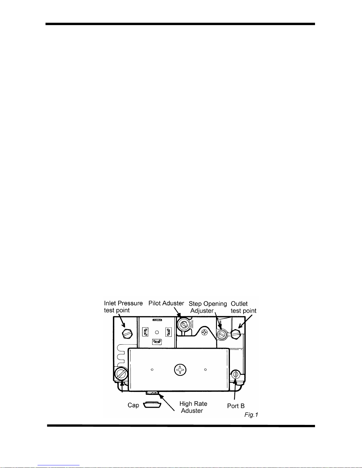
IMPORTANT Check that the burner pressure
is correct by using a manometer connected
to the multifunctional control, and that the
inlet pressure is at least 20 mbar. If it needs
adjustment this can be made using the nut
under the rubber cap on the underside of
the control (see Fig. 1).
The pilot is non-adjustable.
Check the pilot flame supervision by detecting
the voltage on the Pilot solenoid (PL on the
sequence board), turn off the gas cock. The
voltage on the valve should disappear within
ONE second.
Page 12
Condensing Boiler 11 7/5/99
The gas valve opens in two steps, the first lowrate step can be adjusted to the required 5
mBar in the following manner.
Fit a U gauge to the outlet pressure testpoint
and remove plug from 'Port B'. With a finger
sealing 'Port B', start boiler and observe
pressure, adjust with 'Step opening adjuster'.
Note: The step opening action takes 20
seconds to reset after each operation.
If fitted check the operation of the system
bypass with system hot, the minimum flow rate
through the boiler should be as shown in the
Datatable.
Set the pump speed to the highest setting that
does not provoke unreasonable operational
noise within the system.
(Sealed Systems only : re-pressure to
required pressure and set the gauge indicator)
With the system hot, check again for water
soundness. Refit the case to the boiler. Add
remainder of corrosion inhibitor. Balance the
system in the normal way to obtain even
heating of all radiators.
If fitted set the cylinder thermostat to 60oC, or
lower if preferred.
Explain and demonstrate the operation of the
system to the user.
Note: The boiler is fitted with a blocked
drain device and syphon trap to safeguard
the boiler and help defer the effects from the
possible freezing of the condensate
pipework in extreme weather.
The householder should be made aware of
this feature and, that in the event of blocked
condensate pipework, for example frozen,
the boiler will automatically stop
functioning. It will start again as soon as the
blockage has cleared.
Commission Check List (hydraulic)
The key points which must be observed closely
are shown below.
With radiator valves and vents open fill system.
Do not use pump. Do not light gas
Check for and rectify leaks.
Drain to flush system.
Refill system adding 3/4 of the inhibitor.
Do not light boiler.
Vent all radiator and air release points.
Run pump for 5-10 second bursts and revent.
Do not light boiler.
Run pump for at least 30 minutes.
Stop at 5 minute intervals to vent.
Continue venting until no more air noise can be
heard.
Light boiler and run at max thermostat setting.
Continue for 15minutes,
venting every 5 minutes.
Add remainder of inhibitor.
Page 13
Page 14
Page 15
Page 16
Page 17
Page 18
Page 19
Page 20
Page 21

Condensing Boilers 20 12/3/99
FAULT FINDING
General Information
The electrical sequence in the boiler is very straight forward and faults can easily be
tracked down if this simple sequence is followed.
Systemcontrols-------ControlStat-------FlueStat------OverheatStat------PressureSwitch----------Ignition
The lamps on the front panel indicate several of the stages in the ignition sequence.
When the system controls and the programmer are calling for heat, power is fed to the
boiler initiating the following sequence.
Mains voltage appears at terminal 3. and the ON( ) lamp is illuminated. Provided the flue,
overheat and control thermostat are all closed (cold), the fan starts up, the pressure switch
detects the correct airflow and that the condensate drain is not blocked then, switches over.
The PILOT ( ) lamp illuminates, the pilot gas valve opens and the sequence board
provides a spark at the pilot electrode.
The pilot flame is detected and the sequence board energises the main gas valve and the
RUNNING ( ) lamp is illuminated.
The pilot flame lights the burner, and it stays alight until turned off by the control
thermostat, a safety thermostat (in the case of a fault condition) or by the system controls).
The flue thermostat will trip if the flue exceeds a preset temperature, the LOCKOUT
( )lamp will illuminate.
The overheat thermostat will trip if the water flow rate is insufficient, the LOCKOUT ( )
lamp will illuminate.
NOTE: The boiler has a built-in delay timer that only operates on the Control Thermostat
cycles, it does not delay requests to fire from the System Controls. An indicator on the
Pump Overrun board shows when the delay is in operation.
WARNING: BEFORE COMMENCING OR COMPLETING ANY ELECTRICAL WORK ON
THE APPLIANCE, IT IS RECOMMENDED THAT THE BASIC SAFETY CHECKS FOR
EARTH CONTINUITY, SHORT CIRCUIT, POLARITY AND RESISTANCE TO EARTH ARE
MADE. ALL WORK CARRIED OUT SHOULD FOLLOW GUIDELINES LAID DOWN BY
THE IEE.
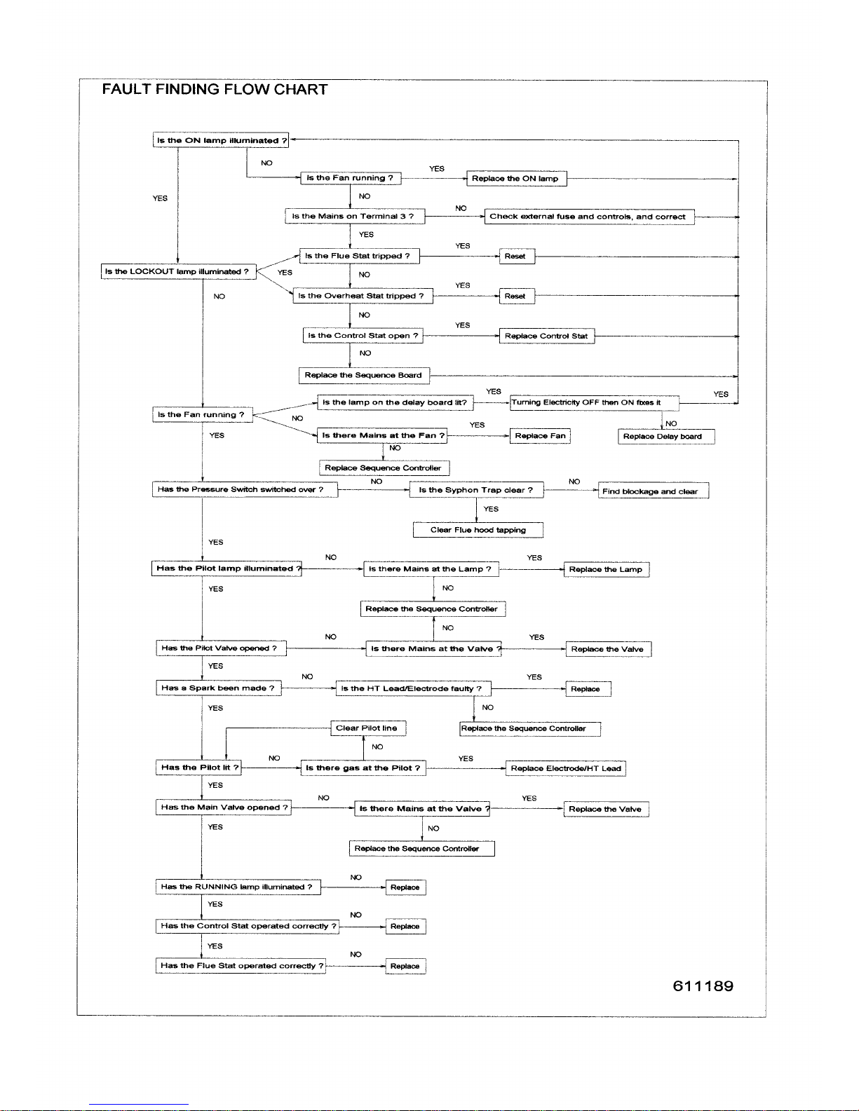
Fault Finding Flow Chart
The Flow chart that follows assumes that the system controls are calling for heat and that
the boiler temperature is colder than the Control Thermostat setting, and should therefore
be firing.
For clarity this chart has been printed on the full page following, the rest of this page is
intentionally left blank.
Page 22
Page 23

Condensing Boiler 22 3/1/00
SERVICING
Health and Safety Statement :
This product contains no asbestos.
Routine
To ensure continued efficient operation of the
appliance it is recommended that it is checked
and serviced at regular intervals.
The frequency of servicing will depend upon
the particular installation and usage but in
general once per year should be adequate.
It is law that any service work should be carried
out by Corgi registered personnel.
1. Clean burner and combustion chamber.
2. Check pilot and burner gas supply.
3. Check condition of ignition sensing probe.
4. Check boiler pipework joints for leaks.
5. Check condensate pipework for leaks.
6. Check heat exchangers, flue and air duct
are clear of any obstruction, and not
leaking.
7. Check the Fan.
8. Check and clear the condensate exit on the
secondary heat exchanger by removing the
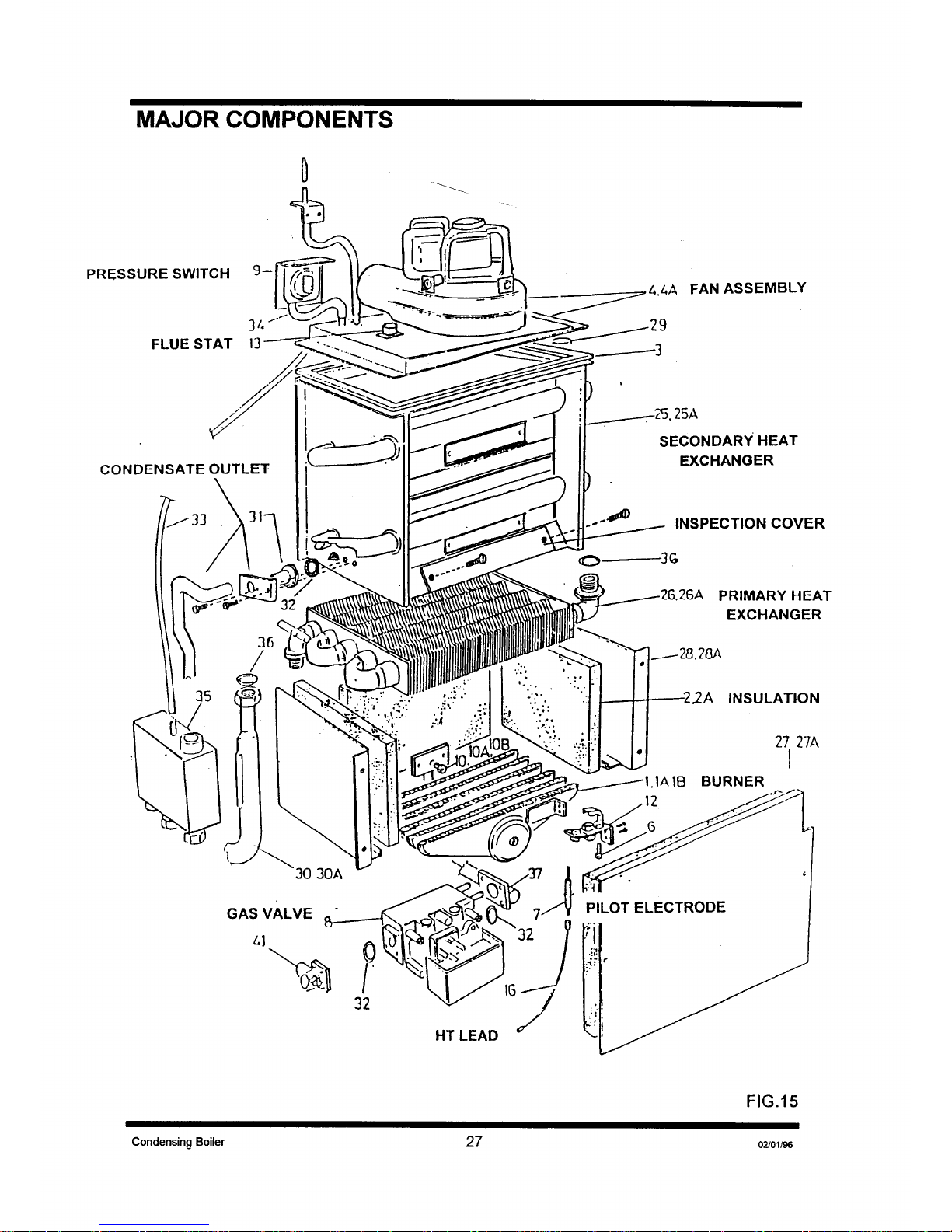
Condensate Outlet and the Inspection
Cover (Fig. 15).
9. Check and clear the condensate syphon.
Follow the procedures given in Changing
Components for parts removal in addition to
the following notes.
1.Heat Exchangers
Remove the panel in front of the secondary
heat exchanger to gain access to inner
inspection panels on the secondary and to
view the primary (the lowest inspection panel
also gives a view of the primary). Also view
from beneath the primary. Clean as required.
If in doubt, drain the system and remove for
inspection.
2.Condensate Syphon
With a suitable bowl to catch the water,
unscrew the two drain-caps on the underside
of the Syphon trap and drain the water.
Remove any solids and replace caps. (fig 14)
CHANGING COMPONENTS
THERE ARE NO REPAIRABLE ITEMS, IF NOT
WORKING AN ITEM MUST BE REPLACED.
The boiler is in two major sections, the Case,
and the Electrical Tray, The Major Components
Diagram shows where the items are to be
found.
Behind the Electrical Tray
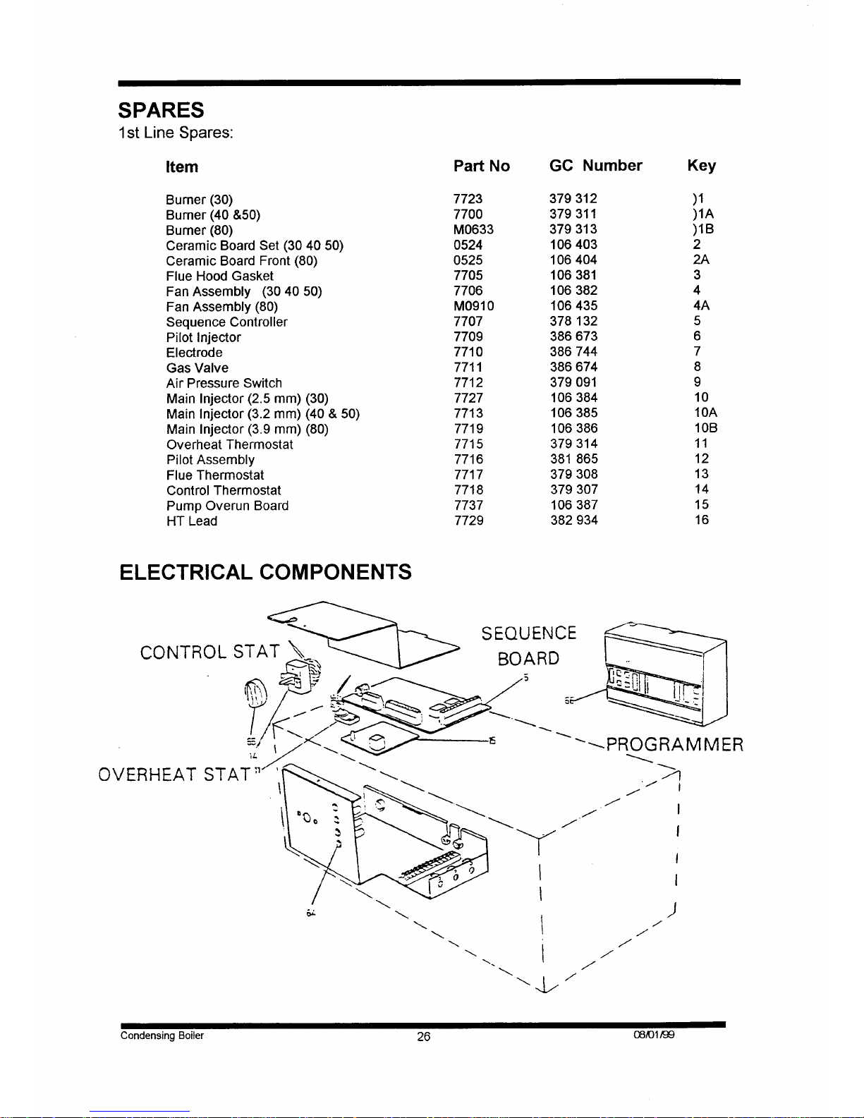
1. Sequence Controller.
2. Panel Indicators.
3. Multifunctional Control.
4. Programmer (where fitted).
5. Pump overrun board.
Behind the Case
6. Fan.
7. Air Pressure Switch.
8. Flue Thermostat.
9. Control Thermostat.
10. Overheat Cut-off Device.
11. HT Lead.
12. Pilot Assembly.
13. Burner.
14. Main Injector.
15. Combustion Chamber Insulation.
16. Primary Heat Exchanger.
17. Secondary Heat Exchanger.
Servicing behind the Electrical Tray
To Remove the Electrical tray
• Disconnect the electrical supply from the
boiler and system.
• Undo the two screws on the front fascia.
• Slide the Electrical Tray forward a short
way, then lower. Remove the cover over the
components.
DO NOT STRAIN THE CABLES, USE THE
SUPPORT PROVIDED.
1. Sequence Controller
• Lower the Electrical Tray.
• Remove the single screw that retains the
inner cover.
• Prise off the multiway connectors away from
the Sequence Controller.
• Pull off the HT Lead from the Controller.
• Unclip the Sequence Controller from the
four pillars.
Page 24
Condensing Boiler 23 3/1/00
• Replace the Sequence Controller.
• Reassembly is the reverse.
• Check the Flame Supervision drop out by
lighting the boiler, putting a voltmeter across
the Pilot solenoid and then turning off the
gas cock. The valve should shut in less than
ONE second.
2. Panel Indicators
• Lower the Electrical Tray.
• Remove the single screw that retains the
inner cover
• Pull off the electrical terminals from the
faulty Indicator.
• Remove the Control Thermostat knob.
• Undo the two M4 screws left and right of the
thermostat shaft.
• Undo the single M5 screw beside the 12
way electrical terminal and move the
Chassis back.
• Slide the Indicator forward out of the
Chassis, and slide in a replacement.
• Reassembly is the reverse.
3. Multifunctional Control
• Lower the Electrical Tray.
• Turn the Gas Cock off.
• Pull off the electrical connector from the
Multifunctional Control.
• Release the pilot feed tube.
• Undo the four shoulder bolts at each end of
the valve.
TAKE CARE TO SUPPORT THE VALVE AS
IT IS RELEASED.
• Replacement is the reverse.
• When secure, attach a manometer to the
burner pressure tapping on the right hand
side of the valve.
• Turn on gas and electrical supply.
• Set burner gas pressure with the adjuster
beneath the rubber cap on the underside of
the Multifunctional Control.
• The gas valve opens in two steps, the first
low-rate step can be adjusted to the
required 5 mBar in the following manner.
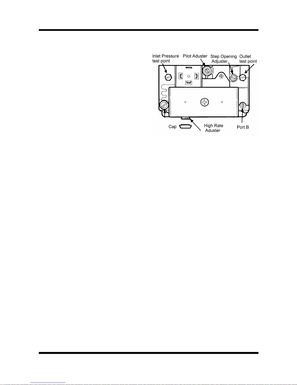
• Remove the plug from 'Port B'. With a finger
sealing 'Port B', start boiler and observe
pressure, adjust with 'Step opening
adjuster'.
Note: The step opening action takes 20
seconds to reset after each operation.
4. Programmer (when factory fitted)
• Lower the Electrical Tray.
• Tip the Electrical Tray forward to allow
access to the two M5 screws above the
programmer.
• Undo these screws and remove
engagement plate.
• Lift out programmer and release it from its
backplate by the two screws in the bottom of
the programmer.
• Reassembly is the reverse.
• (Make certain the engagement plate fits the
slot in the programmer before securing it
with the two M5 screws.)
5. Pump Overrun Board
• Lower the Electrical Tray.
• Remove the single screw that retains the
inner cover
• Release the board from the chassis by
squeezing the supports whilst lifting the
board.
• Disconnect each lead in turn, whilst
connecting up the same lead from the new
board.
• Push the new board onto its supports.
• Reassembly is the reverse.
Removing the Case
• Lower the Electrical Tray but not the inner
cover.
• Undo the two M5 screws at the base of the
Case.
Page 25

Condensing Boiler 24 3/1/00
• Lift the Case straight up about half an inch
(12mm).
• Gently pull the Case straight forward off the
hidden studs at the top of the boiler. (The
cover hangs on two studs in keyhole slots)
• Examine the sealing strip for damage and
replace if necessary.
• Place the Case somewhere safe from
damage
IMPORTANT: FAILURE TO CORRECTLY
LOCATE THE APPLIANCE CASE COULD
RESULT IN LEAKAGE OF COMBUSTION
PRODUCTS INTO THE ROOM.
6. Fan Assembly
• Lower the Electrical Tray.
• Remove the Case.
• Undo the two M5 screws holding the Fan
Protection Hoop and remove.
• Pull the electrical connectors off the Fan.
• Gently pull the pressure tubing off the
tappings on the Flue Hood.
• Undo the two screws holding the Flue Hood
and lift away.
• Reassembly is the reverse.
7. Air Pressure Switch
• Lower the Electrical Tray.
• Remove the Case.
• Pull the electrical connectors off the Air
Pressure Switch.
• Gently pull the pressure tubing off the both
tappings on the switch.
• Undo the two M4 screws holding the Air
Pressure Switch to its bracket on to the
Back Panel and lift away.
8. Flue Thermostat
• Lower the Electrical Tray.
• Remove the Case.
• Pull the electrical connectors off the Flue
Thermostat.
• Reassembly is the reverse.
9. Control Thermostat
• Lower the Electrical Tray.
• Remove the single screw that holds the
inner cover.
• Remove the Case.
• Pull the electrical connectors off the Control
Thermostat.
• Pull off the Control Thermostat Knob.
• Undo the two M4 screws beneath the Knob.
• Remove the retaining clip from the
Thermostat Pocket.
• Release the capillary retaining clamp where
it exits the case.
• Pull the Control Thermostat phial out of its
pocket and lift away.
• Reassembly is the reverse.
10. Overheat Cut-off Device
• Lower the Electrical Tray.
• Remove the single screw that retains the
inner cover
• Remove the Case.
• Undo the terminals of the Overheat Cut-off
Device in the 12 way electrical terminal.
• Pull off the Control Thermostat Knob then
undo the two M4 screws left and right of the
thermostat shaft and undo the single M5
screw beside the 12 way electrical terminal.
• Carefully lift the Chassis to expose the nut
holding the Overheat Cut-off Device
• Remove the retaining clip from the
Thermostat Pocket.
• Release the phial retaining clamp where it
exits the case.
• Pull the Overheat Cut-off Device phial out of
its pocket and lift away.
• Reassembly is the reverse.
11. Electrode and HT Lead
• Lower the Electrical Tray.
• Remove the single screw that holds the
inner cover.
• Remove the Case.
• Undo the left and right screws holding the
Front Burner Baffle.
• Remove the front baffle.
• Release the tube nut holding the electrode
to the Pilot Burner.
• Pull off the HT Lead from the Sequence
Controller.
• Carefully withdraw the Electrode and HT
Lead.
• Reassembly is the reverse.
12. Pilot Assembly
• Lower the Electrical Tray.
Page 26

Condensing Boiler 25 3/1/00
• Remove the Case.
• Undo the left and right screws holding the
Front Burner Baffle and remove. If access is
restricted also remove the right hand baffle.
• Release the tube nut holding the electrode
to the Pilot Burner.
• Undo the Pilot gas tube from the Pilot
Assembly and gently lever downwards away
from the Pilot.
• Undo the two screws retaining the Pilot
Assembly.
• Reassembly is the reverse
NB The pilot is not adjustable.
13. Burner
• Lower the Electrical Tray.
• Remove the Case.
• Remove the Front Baffle.
• Remove the Combustion Chamber front by
releasing the four M5 screws.
• Undo the two screws securing the Pilot
Assembly and gently lever downwards.
• Pull the Burner forward off the two studs at
the rear.
• Reassembly is the reverse.
14. Main Injector
• Lower the Electrical Tray.
• Remove the Case.
• Remove the Burner.
• Undo the Main Injector from the manifold.
• Reassembly is the reverse.
15. Combustion Chamber Insulation
• Lower the Electrical Tray.
• Remove the Case.
• Remove the baffles by releasing the two self
tapping screws holding the Front Baffle,
then undo the four M5 screws holding the
baffles onto the Back Panel
• Remove the Burner, as in 13.
• Undo the four M5 screws in the front
Insulation Panel.
• Undo the four M5 screws holding the
Chamber to the Back Panel and lower
downwards and away.
• Replace the Insulation Panels in the
Chamber.
• Reassembly is the reverse.
16. Primary Heat Exchanger
• Lower the Electrical Tray.
• Remove the Case.
• Remove the front baffle.
• Remove or cover the Burner.
• Remove the Combustion Chamber.
• Remove the clip holding the Overheat Phial
on the left hand side of the Heat Exchanger
and withdraw the phial.
• Drain the Boiler of water.
• Undo the flow and return connections to the
Heat Exchanger and lower away.
• Reassembly is the reverse.
17. Secondary Heat Exchanger
• Lower the Electrical Tray.
• Remove the Case.
• Remove the Flue Thermostat.
• Remove the Fan Assembly.
• Drain the Boiler of water.
• Undo the flow and return connections to the
secondary Heat Exchanger.
• Release the Condensate connection
clamping plate.
• Undo the four M5 screws holding the
Secondary Heat Exchanger to the Back
Panel and lift away.
• Reassembly is the reverse.
Page 27
Page 28
Page 29
Page 30
 Loading...