

Cooper Crouse-Hinds GmbH
77
77
7
Explosion protected terminal boxes GHG 791 01 and
GHG 791 02
1 Technical data
Terminal box GHG 791 01/GHG 721 02
Marking acc. to 94/9/EC and directice: II 2 G Ex e d m ia IIC T6
II 2 D Ex tD A21 IP 66 T80 °C
EC type examination certificate: PTB 00 ATEX 3108
Rated voltage: up to 690 V
Rated current: acc. to table an the inside of the enclosure cover
Perm. ambient temperature: -20° C up to +40° C (catalogue version)
Special versions permit deviating temperature ranges.
Perm. storage temperature in original packing: -40° C up to +80° C
Schutzart nach EN/IEC 60529: IP 66 (catalogue version)
Insulation class acc. to EN/IEC 61140: I - is complied with by the terminal boxes
II - with internal earth plate
Supply terminal: acc. to customers specification and as certificate
GHG 791 01 max. 4mm²
GHG 791 02 max. 6mm²
Cable entries: acc. to customers specification and as certificate
Test torques:
Cover screws 1.20 Nm
Cap nut of the M12 entry 1.65 Nm
Cap nut of the M16 entry 2.50 Nm
Cap nut of the M20 entry 2.50 Nm
Cap nut of the M25 entry 3.50 Nm
Cap nut of the M32 entry 5.00 Nm
Weight GHG 791 01:
empty weight approx. 0.25 kg
with internal earth plate approx. 0.30 kg
Weight GHG 791 02:
empty weight approx. 0.45 kg
with internal earth plate approx. 0.52 kg
Intrinsically safe circuits:
Max. safe voltage U
m
690 V eff
Safe galvanic isolation from all other circuits
and earth
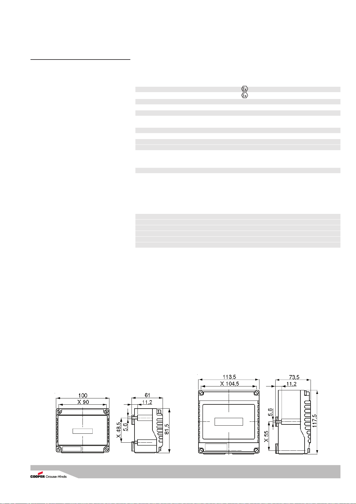
Terminal box GHG 791 02
Terminal box GHG 791 01 Terminal box GHG 791 02
Dimensions in mm
X = fixing dimensions
www.malux.se
Cooper Crouse-Hinds GmbH
88
88
8
2 Safety instructions
The terminal boxes GHG 791 are
not suitable for Zone 0 and Zone
20 hazardous areas.
The operations must be carried out by
electrical suitably trained in hazardous
areea with knowledge of increased safety
explosion protection.
The temperature class and explosion
group marked on the terminal boxes shall
be observed.
The requirements of the EN 61241-0 and -1
regarding excessive dust deposits and
temperature to be considered from the
user.
Modifications to the terminal boxes or
changes of their design are not
permitted.
They shall be used for their intended
purpose and in perfect and clean
condition.
For replacement and repair only genuine
COOPER CROUSE-HINDS spare parts
shall be used. Repairs that affect the
explosion protection, may only be carried
out by COOPER CROUSE-HINDS or a
qualified electrician in compliance with
the respective national regulations.
Prior to taking the terminal boxes into
operation, they shall be checked in
accordance with the instruction as per
section 6.
Before the initial operation, any foreign
matter shall be removed from the
terminal boxes.
Observe the national safety rules and
regulations for prevention of accidents as
well as the safety instructions included in
these operating instructions and set in
italics the same as this text!
Explosion protected terminal boxes GHG 791 01 and
GHG 791 02
3 Conformity with standards
The apparat is conform to the standards
specified in the EC-Declaration of conformity,
enclosed separately.
It has been designed, manufactured and
tested according to the state of the art and to
DIN EN ISO 9001.
94/9 EC: Equipment and protective systems
intended for use in potentially explosive atmospheres.
The apparats fulfil further requirements, such
as the EC directive on electromagnetic
compatibility (2004/108/EEC).
5 Use/Properties
The terminal boxes are intended for the
distribution of electrical energy e.g. light
circuits, heater circuits, control circuits,
intrinsically safe circuits etc. in hazardous
areas (see technical data). The temperature
class, explosion group and permissible
ambient temperature, see technical data.
The electrical limiting values that are
decisive for the intrinsic safety shall be
observed.
The terminal boxes can also be used in a
„normal industrial area“.
The data as per point 3 and 4 shall be
taken into account with the use.
Applications other than described are not
permitted without COOPER CROUSEHINDS’s prior written consent.
For the operation, the instructions stated
in section 7 of the operating instructions
shall be observed.
The user alone is responsible for the
appropriate use of this terminal box in
consideration of the basic conditions
existing at the plant (see technical data).
6 Installation
For the mounting and operation, the
respective national regulations (e. g. Betr.Si.V,
equipment safety law for Germany) as well as
the general rules of engineering shall be
observed.
4 Field of application
The terminal boxes GHG 791 01 and GHG
791 02 are suitable for use in Zone 1 and 2
as well as in Zones 21 and 22 hazardous
areas acc. to IEC 60 079-10 and
IEC 60 079-14!
The enclosure materials employed, including
the exterior metal parts, are made of highquality materials which ensure a corrosion
protection and resistance to chemical
substances corresponding to the
requirements in a “normal industrial
atmosphere”:
- impact resistant polyamide
- special steel AISI 316 L
In case of use in an extremely aggresive
atmosphere, please refer to manufacturer.
Terminal box GHG 791 01
Fig. 1
www.malux.se

Cooper Crouse-Hinds GmbH
99
99
9
Explosion protected terminal boxes GHG 791 01 and
GHG 791 02
6.1 Mounting
The terminal boxes can be mounted without
opening their enclosure.
In case the terminal boxess are mounted
directly onto the wall, they may rest evenly
only at the respective fastening points. The
chosen screw shall match the fastening hole
(see dimensional drawing) and it must not
damage the hole (e. g. use of a washer).
The device shall be fastened diagonally with
at least 2 screws.
If the screws are overtightened, the
apparatus can be damaged.
The terminal boxes are suitable for fixing onto
COOPER CROUSE-HINDS apparatus holders
size 1+ 2 by means of self-cutting screws (see
fig. 2, fixing point "B").
The respective mounting instructions
shall be observed.
6.2 Opening the device/
Electrical connection
Before opening the apparatus, it is
necessary to ensure that there is no
voltage or to take suitable protective
measures.
The electrical connection of the device
may only be carried out by skilled staff ina
acc. to 60 079-14.
The insulation of the conductors shall
reach up to the terminal. The conductor
itself shall not be damaged.
The properly bared conductors of the cables
shall be connected, taking into account the
respective regulations.
The connectible min. and max. conductor
cross-sections will have to be observed (see
technical data).
All screws and/or nuts of the supply
terminals, also of those remaining unused,
shall be tightened down.
The conductors shall be connected with
special care in order to maintain the
explosion category.
The supply terminals are designed for the
connection of copper conductors. If multi- or
fine-wire connecting cables are used, the
wire ends will have to be handled in acc. with
the applicable national and international rules
(e. g. use of ferrules).
The table indicating the current load
values which is provided on the cover
inside of the terminal boxes is to be
observed.
B
for walland
channel
fixing
for pipe
fixing
Size 1 apparatus holder for GHG 791 01
Fig. 2
Size 2 apparatus holder for GHG 791 02
B
for wall
and
channel
fixing
for pipe
fixing
6.3 Cable entries (KLE);
blanking plugs
Generally, only certified cable entries and
blanking plugs may be used.
Flexible cables are to be used with
trumpet-shaped cable glands or other
suitable entries with additional pull-relief.
The mounting directives applicable to the
fitted cable entries are to be observed.
When using cable entries with a lower IP
protection than that which applies to the
device (see technical data, page 9 + 10),
the IP protection of the whole device will
be reduced.
In order to establish the minimum protection
category, unused holes have to be closed
with a certified blanking plug.
Care has to be taken that when fitting the
cable entries, sealing inserts appropriate to
the cable diameter are used.
In case of sealing inserts that are cut out, it
will have to be ensured that the insert is
properly adapted to the cable diameter.
When using cable entries for fixed cables it is
necessary to ensure that no inadmissible
high mechanical stress is applied to the cable
entry or its seal.
Intrinsically safe circuits shall be fed through
cable entries that are colour-coded (light
blue).
All vacant metric COOPER CROUSE-HINDS
cable entries are to be closed with the
certified blanking plug for metric cable entries
(see page 8, fig. 1).
In case of mixed equipment Ex e / Ex-i, the
required minimum distances will have to be
kept (see e.g. EN 60079-11).
When apparatus is open, it is necessary to
ensure (disconnect voltage supply) that
no voltage is carried over into the
connected intrinsically safe circuits.
The installation instructions for intrinsically
safe electrical apparatus shall be observed.
It is necessary to ensure that the permissible
external capacitance and inductance of the
special intrinsically safe circuits are not
exceeded.
www.malux.se

Cooper Crouse-Hinds GmbH
1010
1010
10
6.6 Taking into operation
Prior to taking the apparatus into operation,
the tests specified in the relevant national
regulations will have to be carried out.
Apart from that, the correct functioning and
installation of the apparatus in accordance
with these operating instructions and other
applicable regulations will have to be
checked.
Incorrect installation and use of the
terminal boxes can invalidate the
guarantee.
Explosion protected terminal boxes GHG 791 01 and
GHG 791 02
8 Repairs / Overhaul /
Modification
Repairs may only be carried out with genuine
COOPER CROUSE-HINDS spare parts.
Repairs that affect the explosion
protection, may only be carried out by
COOPER CROUSE-HINDS or a qualified
electrician in compliance with the
applicable national rules (EN 60079-19).
Modifications to the apparatus or changes of
its design are not permitted, except for the
mounting of additional cable entries and the
installation of supply terminals in accordance
with the approval of the apparatus.
9 Disposal / Recycling
When the apparatus is disposed of, the
respective national regulations on waste
disposal will have to be observed.
In order to facilitate the recycling of individual
components, plastic parts have been
provided with the identification mark of the
plastic material used.
Subject to modifications or supplement of the
product range.
7 Maintenance/Servicing
The relevant national regulations which
apply to the maintenance/servicing of
electrical apparatus in explosive
atmospheres, shall be observed
(EN 60079-17).
Before opening the enclosure make sure
that the apparatus is disconnected from
the voltage, or take the appropriate
protective measures.
In case of intrinsically safe circuits, working is
permitted while voltage applies.
The required maintenance intervals depend
on the respective application and will
therefore have to be determined by the user
dependent on the conditions of use.
Cleaning:
Because of the risk of an electrostatic
charge, the junction boxes shall only be
cleaned with a damp, non fibrous cloth or
sponge!
When servicing the apparatus, particularly
those parts that are decisive for the type of
protection against explosion, will have to be
checked (e. g. intactness of enclosure, cable
glands, efficacy of the cover gaskets).
If during servicing repairs prove to be
necessary, section 8 of these operating
instructions will have to be observed.
6.5 Closing the device/
cover closure
Any foreign matter shall be removed from
the apparatus.
In order to ensure the required minimum
protection category, the cover screws are to
be tightened down.
Overtightening might impair the
protection category.
In order to ensure the required minimum
protection category, the cable glands shall be
tightened down.
Overtightening might impair the
protection category.
Attention: The metal frame and metal
glands are to be integrated into the
potential equalization.
www.malux.se
 Loading...